

Page 1

Fast Ethernet Switch
USER'S GUIDE
Twenty-Four (24) ports100/10Mbps Fast Ethernet Switch
LINDY Part No. 25021
Page 2

T ABLE OF CONTENTS
1 UNPACKING INFORMATION................................3
2 PRODUCT INTRODUCTION.................................4
2.1 Models...............................................................4
2.2 Key Features......................................................4
2.3 Front Panel ........................................................4
2.3.1 100/10Mbps TP Ports.................................4
2.3.2 Cabling......................................................4
2.3.3 Status LEDs...............................................4
2.4 Rear Panel.........................................................4
2.4.1 Power Socket.............................................4
2.4.2 Fan............................................................4
3 INSTALLATION.....................................................5
3.1 To locatetheswitch on a desktop........................5
3.2 Rackmount placement........................................5
4 HELPFUL SUGGESTIONS....................................6
4.1 Priorto Installation..............................................6
4.2 Half-andFull-Duplex..........................................6
4.3 Fast Ethernet......................................................6
4.4 Auto-Negotiation.................................................6
4.5 MACAddress Table............................................6
5 SampleApplication................................................7
6 PRODUCT SPECIFICATIONS...............................8
2
Page 3
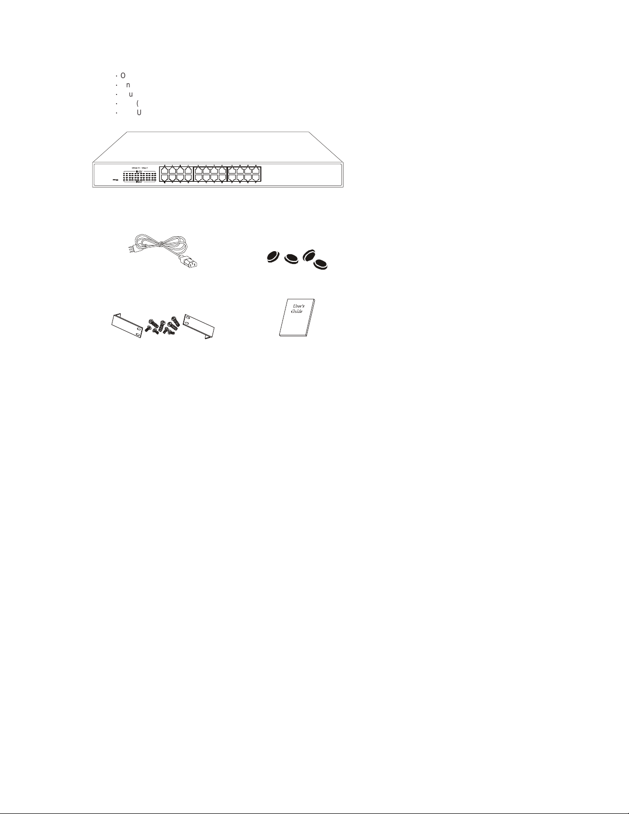
1 UNP ACKING INFORMATION
Thank youfor purchasing theSwitch. Before continuing, please check the contents ofth e product package.This product
packageshould containthe following items:
ƍ
One (1) Switch
ƍ
One (1) Power Cord
ƍ
Four(4) Rubber Feet (fordesktopplacement)
ƍ
One(1) Rackmount Kit
ƍ
This User’sGuide
If anything is missing, please contact your place of purchase.
For19 inches case
PowerC ord Rubber Feet (fordesktop placement)
Rackmount Kit User’sGuide
3
Page 4

2 PRODUCT INTRODUCTION
2.1 Models
The Switch is a multi-speed, versatilenetwork devicec ombining both standard and"Big-Pipe" portsunder the samehood.
The Switch is a twenty-four (24) 100/10MbpsRJ-45 UTP/STPports switch.
2.2 KeyFeatures
ƍ
Twenty-four(24) 100/10Mbps Switch ports.
ƍ
Store-and-Forward technology.
ƍ
Auto-Negotiationsupport for eachTP port.
ƍ
IEEE802.3x Flow-Control support for Full-Duplex operation.
ƍ
Back-Pressure support for Half-Duplexoperation.
ƍ
Bridging capability for 100Mbps and10Mbps segments.
ƍ
All ports supportAuto-MDIXfunction.
2.3 Front Panel
For19 inches case
2.3.1 100/10MbpsTP Ports
Each100/10Mbps TPport provides anAuto-Negotiation function that senses for the attacheddevice's maximum operating
speed and automatically sets the Switch to operate at that speed. Users only need to connect a network device into any TP
port.
2.3.2 Cabling
10Mbps- When transmitting at10Mbps Category3, 4 or 5 TP cabling withRJ-45 socketscan be used.
100Mbps-Totransmit at100Mbps requires Category 5 TPcabling.
Note: Category 5 TPcable is recommended wheneverinstalling newc abling.
2.3.3 Status LEDs
The Switches comewith a completerange of LEDs.The table belowlists each LEDs name, color and a brief description of its
function.
Name Color Function
Pwr Green Lit: Power "On"
LINK/ACT Green Lit: When theport has a valid physicalconnectionwith
FD/COL Amber Lit: Whenport is set to Full-Duplex mode.
Port Type CableType Connector
10BASE-T Category 3, 4 or 5 TP RJ-45
100BASE-TX Cat.5TP RJ-45
another device.
Blinks: When the port is sending or receiving data (Activity).
Blinks:W hen a collisionis detected, when theport is in
Half-Duplex mode.
2.4 Rear Panel
For19 inches case
2.4.1 Power Socket
The Power Socketisdesignedto be used with the power cord includedin the productpackage.
ƍ
Attach the female end of the cord to the power connector on the back panel.
ƍ
Attach the male endof the cord to a grounded power outlet.
2.4.2 Fan
Note: Please keep the fan area clear, so that the cooling function is not impaired.
4
Page 5

3 INST A LLATI ON
TheSwitch is "Plug& Play". Itdoes NOTr equire software configuration.Users can immediatelyus e any of thefeatures of this
productsimply by attaching the cablesand turning on the power.
3.1 To locatethe switch on a desktop
ƍ
Attach the four (4)rubber feet includedin the product package to the bottomof the Switch, onein eachc orner.
ƍ
Place the Switch on a clean, flat desk or tabletop close to a power outlet.
ƍ
Plug in all network connections and the power cord.
ƍ
Turn the power switch to "On".
3.2 Rackmount placement
ƍ
Attach one (1) rackmounting bracket on each side of the Switch front panel and secure each bracket with the provided
screws.
ƍ
Use theother provided screws to secure eachSwitch to the rack.
Use theother provided screws to secure eachHub to the rack.
5
Page 6

4 HELPFUL SUGGESTIONS
4.1 Prior to Installation
Beforeinstalling theSwitch and connectingnetwork devices, it is importantto plan the network's layout.Things you should
considerinclude:
ƍ
DedicatedBandwidth:File servers and other high-traffic hardware improve their performance if they have their own
dedicated 10Mbps or100Mbps bandwidth.
ƍ
Full-Duplex: Determinewhich devicessupport Full-Duplexconnections.
ƍ
Fast Ethernet: Makesure rules for cablelengthsand categoriesare followed.
ƍ
Auto-Negotiation: Devices with different speeds may be easily swapped when the other end of the cableis fixed to a port
with Auto-Negotiation.
Note: If you areusing thelast port’s CrossoverT P connector, youc annot use thelast port’sregular connector.If you useboth
of the last port's TP connector’s at the same time your Switch will not operate properly.
4.2 Half- and Full-Duplex
The Switch supportsboth Half- and Full-Duplexmodes for10B ASE-T and 100BASE-TX.
ƍ
In Half-Duplex mode: Datacannot be transmitted andreceived atthe same time. Attachedd evices mustfinish transmitting
data before they can receive data.
ƍ
In Full-Duplex mode: Data can be transmitted and receivedat the same time.
However:
ƍ
Full-Duplex transmission is only possible between two devices with a dedicated link (e.g., Switch-Switch, Switch-PC)
ƍ
Bothdevices must have Full-Duplex capability
ƍ
Bothdevices must be set toFull-Duplex (e.g.Auto-Negotiation – Auto-Negotiation, Non-Auto-Negotiation to
Non-Auto-Negotiation)
The 100BASE-TX/10BASE-T portson the Switch detectand set the line's operating modeby using their Auto-Negotiation
function.
4.3 Fast Ethernet
100BASE-TXis called"F ast Ethernet". InF ast Ethernet datatravels ten times faster (100Mbps) than in traditional Ethernet
(10Mbps).
Belowis a list of the cable types and connectors supportedby the Switch for 10BASE-Tand 100BASE-TXnetworks.
Port Type CableType Connector
10BASE-T Category 3, 4 or 5 TP RJ-45
100BASE-TX Cat.5 TP RJ-45
Note: Ifyour 10BASE-Tnetwork currentlyuses Category 5TP cabling, you can instantly upgradethe network to a
100BASE-TXnetwork bychanging network devices.
4.4 Auto-Negotiation
Every100/10Mbps dual speed port on theS witch has a built-in"Auto-Negotiation" function. This technology automatically
setsthe best possiblebandwidth ass oon as a connectionis established with anothernetwork device. (Usually at Power “On”
or Reset.) This capability is achieved via theSwitch’s Auto-Negotiation functionthat automaticallydetectsth e modes and
speedsthe second (attached) deviceis capable of.
Evaluating Auto-Negotiation Capability:
If attached device is: The Switch Will Automatically Set Its TP Ports to
100Mbps
noAuto-Negotiation
100Mbps
with Auto-Negotiation
10Mbps
noAuto-Negotiation
10Mbps
with Auto-Negotiation
Note: If the attached device is set to a fixed mode (ex: Forced Full-Duplex) it will not operate as an Auto-Negotiation device.
4.5 MAC Address Table
EveryEthernet data packet includesboth source and destination addresses. This six(6) bytes ID iscalledthe MAC (Media
AccessControl) Address.
The Switch can automatically learn and store MAC addresses. However, the MAC address table is volatile: it disappears
when the Switch is powered “Off” or reset.
Note:When thenetwork needsr econfiguration,we recommend turningoff the powerfirst. After all nodes haveb een moved,
turn the Switch back "On" to rebuild the internal MAC address table.
Operate At:
100Mbps(100BASE-TX, Half-Duplex)
200Mbps(100BASE-TX, Full-Duplex)
10Mbps(10BASE-T, Half-Duplex)
20Mbps(10BASE-T, Full-Duplex)
6
Page 7

5 Sample Application
The optimal application for theSwitchis as a"big pipe" backboneinterconnecting fileservers withbandwidth-hungry
workgroups, departments, andoffices.
8Gigabit portsSwitc h
Mail Server
withGigabitEthernetAdapter
24100/10po rtswith2 Gigabit p ortsswitch
24-Port +2 Giga PortSwi tch
File Server
withGigabitEthernetAdapter
24 ports 10 0/ 1 0Mb ps Fast Ethernet Switch
24 ports 100/10Mb ps Fast E thern et Swi tch
Print er
Pri nt e r Ser ve r
8 ports 100/10Mbps
Fast Ethernet Switch
Workstationswith100/10
FastEthernetAdapters
16 ports 100/ 10M bps
Fast Etherne t Sw itc h
Workstationswith100/10
FastEthernetAdapters
5 ports100 /10Mbps
5
Fast Et hernet Switch
P
o
t
r
S
w
t
i
c
h
5
4
3
2
1
Workstationswith100/10
FastEthernetAdapters
Workstationswith100/10
FastEthernetAdapters
7
Page 8

6 PRODUCT SPECIFICATIONS
Models Twenty-Four(24) ports100/10Mbps Fast EthernetSwitch
Standards 10BASE-TIEEE 802.3
Ports Twenty-four(24) 100BASE-TX
MediaSupport 10BASE-TCategory 3, 4 or5 TP
Bandwidth 100BASE-TX 200/100/20/10Mbps
Forwarding /
FilteringRate
Latency 9 µsec @100Mbps,minimum
MAC Addresses 8K six (6)-bytes entries maximum, self-learning
Buffer Memory 2.5Mb
DuplexModes Auto-Negotiation
Crossover All theTP ports supportAuto-MDIXfunction
LED Indicators One (1) forPower
PowerSupply Full rangeAuto-Switching
Power Consumption 21.5 watt max
Environment OperatingTemp: 0° ~45°C(32° ~113°F)
Certifications FCC ClassA
Dimensions
(For 13 inches and 19 inches width)
100BASE-TXIEEE 802.3u
100BASE-TXCategory 5TP
148,810packets/second per port @100Mbps, max.
14,881packets/second per port@ 10Mbps, max.
70 µsec@ 10Mbps, minimum
One(1) per port for Link /ACT
One(1) per port for Full-Duplex/Collision
Inputv oltage: 100 ~ 240 +/-10%VAC/50 ~ 60 Hz
Storage Temp: -20° ~70°C (-4° ~ 158°F)
Humidity:10% ~ 90% non-condensing
CE Mark
For19 inches width:
442x184x44mm(17.40x7.24x1.73inches)
This equipment has been tested and found to comply with the limits for a ClassA computing device pursuant to
Part 15 of FCC Rules, which are designed to provide reasonable protection against electromagnetic interference
in a commercial environment.
Changes or modifications to the equipment not expressly approved by the party responsible for compliance could
void the user's authority to operate the equipment.
This is a ClassA product. In a domestic environment this product may cause radio interference in which case the
user may be required to take adequate measures.
8
FCC WARNING
CE MARKWARNING
 Loading...