

Page 1

16-Port 10/100Mbps Fast Ethernet Switch
16-Port 10/100Mbps Fast Ethernet Switch with 1 Fiber port
USER'S GUIDE
LINDY Part No. 25020
Page 2

2
T ABLE OF CONTENTS
1 UNPACKING INFORMATION.................................................3
2 PRODUCT INTRODUCTION..................................................4
2.1 Models ..................................................................................... 4
2.2 KEYFEATURES......................................................................4
2.3 The Front Panel....................................................................... 4
2.3.1 Port Speeds..................................................................... 4
2.3.2 Cabling............................................................................ 4
2.3.3 StatusLEDs..................................................................... 5
2.4 The Rear Panel........................................................................ 5
2.4.1 Power Socket................................................................... 5
2.4.2 DIP-Switch.......................................................................6
2.5 Broadcast Storm Control...........................................................6
3 INSTALLAT ION......................................................................7
3.1 LOCATE THE SWITCH............................................................ 7
3.2 RACKMOUNT PLACEMENT.................................................... 7
4 HELPFUL SUGGESTIONS ....................................................8
4.1 Priorto Installation....................................................................8
4.2 Half-and Full-Duplex................................................................ 8
4.3 Auto-Negotiation.......................................................................8
4.4 MACAddress Table.................................................................. 8
5 SAMPLE APPLICATION........................................................9
6 PRODUCT SPECIFICATIONS..............................................10
Page 3
3
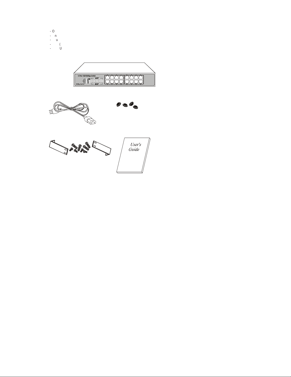
1 UNP ACKING INFORMAT ION
Thank you for purchasingthis Switch. Before continuing,please check the contentsof th e product package. This product
packageshould contain the following items:
ƍ
One(1) 16-PortSwitch
ƍ
One (1) Power Cord
ƍ
Four(4) Rubber Feet(for desktopplacement)
ƍ
One (1) Rackmount Kit (optional)
ƍ
This User’s Guide
If anything is missing, please contact your place of purchase.
16-Port Switch
PowerC ord Rubber Feet
Rackmount Kit (optional) User’s Guide
Page 4

4
2 PRODUCT INTRODUCTION
2.1 Models
This Switch is a multi-speed, versatile networkdevice combining both Copperand Fiber p orts under the same hood.
The number and typesof portsfor this Switchare listed below.
2.2 KEYFEATURES
ƍ
Independent bandwidthfor each port.
ƍ
10/100MbpsTP ports withAuto-Negotiation supported.
ƍ
Bridging capability for100Mbps and 10Mbpssegments.
ƍ
Provides Store-and-Forward forwarding scheme.
ƍ
AutoMDI/MDIX function supported.
ƍ
IEEE802.3xFlow-Controlsupported for Full-Duplex operation.
ƍ
Back-PressureFl ow-Controlsupported for Half-Duplex operation.
ƍ
4M bits Buffer Memory.
ƍ
8K MACAddress Table.
ƍ
SupportsQoS function on each port, based on 802.1p/802.1q VLAN Tag priority and TCP/IPHeader’s TOS/DS.
ƍ
Four(4) Trunk groups supported.
ƍ
Aging function supported,the aging timeis about 300 sec.
ƍ
Broadcast Stormcontrol supported.
ƍ
SupportsPort-BasedH ome VLANƑAllow home networks to share a common server or router.
ƍ
Desktop size with rack mounting capability.
2.3 The Front Panel
Model 100BASE-TX/ 10BASE-T port 100BASE-FXport
16-Portswitch Sixteen (16) N/A
16-Port Switch
2.3.1 Port Speeds
10/100MbpsTP ports
Each10/100MbpsTP port provides anAuto-Negotiation function and an Auto-Crossover(Auto-MDI/MDIX)function that senses
for the attached device's maximum operating speed and automatically sets the Switch to operate at that speed. Each TP port
uses RJ-45 connector that allows network TP cables to be easily attached or removed. Users only need to connect a network
device into any TP port and the Switch will do the rest.
2.3.2 Cabling
10Mbps– Category 3, 4, or 5 TP cabling can be used for transmittingdata at 10Mbps or 20Mbpsbandwidth on 10BASE-T
networks.
100Mbps– Only Category 5 TP cabling can be used for transmitting data at 100Mbps or200Mbps bandwidth on 100BASE-TX
networks.
PortType CableType Connector
10BASE-T Category 3, 4 or 5 TP RJ-45
100BASE-TX Category5 T P RJ-45
Note: Category 5 TP cable should be used whenever installingnew TP cabling.
Page 5

5
2.3.3 Status LEDs
This Switch comes with a complete range of LEDs. The table below lists each LED’s name,color and a brief description of its
function.
ƍ
One (1) for power On/Off.
ƍ
One(1) per port for Link/Activity.
ƍ
One(1) per port for Full-Duplex/Collision.
ƍ
Four(4) for TRUNK Groups status.
ƍ
Two(2) for Home VLAN status.
Name Color Function
Pwr Green Lit: Power "On"
LINK/ACT Green Lit: When the port has a valid physical connection (Link) with another
FD/COL Amber Lit: When the port is set to Full-Duplexmode.
A Green Lit:TRUNK AGroup Enable (Port#1,#2, #9, #10 are a TRUNK Port)
TRUNK
B Green Lit:TRUNK B Group Enable (Port#3,#4, #11, #12 are a TRUNK Port)
C Green Lit:TRUNK C Group Enable(Port #5, #6, #13, #14 are a TRUNK Port)
D Green Lit:TRUNK D Group Enable(Port #7, #8, #15, #16 are a TRUNK Port)
A Amber Lit: Support 14 VLANs (Port#1Ƒ#7, #9-#15) with 2 overlapping ports
Home
VLAN
B Amber Lit: Support 15 VLANs (Port#1
device.
Blinks: When the port is sending or receiving data (Activity).
Blinks:When a collision is detected,in Half-Duplexmode.
Blink:When theTRUNK Group has a port link Failure with another device.
Blinks:When the TRUNK Group has a port link Failure with another device.
Blinks:When the TRUNK Group has a port link Failure with another device.
Blinks:When the TRUNK Group has a port link Failure with another device.
(Port#8,#16) topology
Ƒ
topology
#15) with 1 overlapping port(Port#16)
We provideFour (4) LEDs to indicatethe TRUNK status.
TheTRUNK LED will be lit on when the trunk is enable, it will blink when any physical port link failuresoccur within the enabled
trunk port.
If the TRUNK LED blinks during thenormal operation,please ch eck the trunk groupports link status.
2.4 The Rear Panel
16-Port Switch
2.4.1 Power Socket
The PowerS ocket is d esigned to be used with the power cordincluded in theproduct package.
ƍ
Attach the female end of the cord to the power connector on the back panel.
ƍ
Attach the male end of th e cordto a grounded power outlet.
Note:To reset the switch, Remove the power cord and re-attach it .
ƍ
The switchmust be reset when the MACAddress table needs to be rebuilt.
ƍ
The switch must be reset when the configurations (on real panel) are changed.
Page 6

6
2.4.2 DIP-Switch
This Switch provides DIP-Switches setting to configuration, the configuration setting as below:
a. Home VLAN
We have provided two DIP-Switches for the Home VLAN setting.
Leftside D IP-Switch Rightside DIP-Switch
SW up Home VLAN Disable Home VLAN TYPE A
SW down Home VLAN Enable Home VLAN TYPE B
Home VLAN TYPE A: Select14 VLANs (port#1Ƒ#7, #9Ƒ#15) withtwo overlapping ports (port#8,#16) topology. (VLAN1:
port#1,#8, #16; VLAN2:port#2, #8, #16; VLAN3: port#3, #8, #16, …; VLAN14: port#15, #8, #16)
Home VLAN TYPE B:
Select15 VLANs(port#1Ƒ#15) withone overlapping port(port#16)topology.(VLAN1: port#1,#16; VLAN2:
port#2,#16; …; VLAN15:port#15, #16)
This functionfornetwork topology securityconfiguration.When thePort-Based securityfunction is enabled, the 16-PortsSwitch
can be configuredas14 (or 15) individual VLANsthat share the same two (or one) overlappingport(s).T his 14 VLANs or 15
VLANs topology is useful to allow home networks to share common servers or routers, this function can be used on Fiber ToThe
Home(FTTH) orEthernetToThe Home(ETTH) application.
Note: Only whenthe left side DIP-Switch move to “ON”, the function of the right side DIP-Switch would be active.
b. TRUNK
We havesupport Four DIP-Switchesfor the TRUNK Portsetting.
ABCD
SW up TRUNKA Disable TRUNK B Disable TRUNK C Disable TRUNKD Disable
SW down TRUNK AEnable TRUNK B Enable TRUNKC Enable TRUNK D Enable
ƍ
TRUNKA: Port#1, #2, #9, #10
ƍ
TRUNK B: Port#3,#4, #11, #12
ƍ
TRUNK C: Port#5,#6, #13, #14
ƍ
TRUNK D: Port#7,#8, #15, #16
If the trunk function enable, it can be provided 800Mbps bandwidth between two devices,it is useful to allow high bandwidth in
Backbone or server connection.
Note: Ifthe Home VLAN function is enabled, it will disable the TRUNK function setting.
c. 100FX (100BASE-FXoperation mode setting) (only for Switch w/ Fiber port)
This DIP-Switch is setting to configuration 100Mbps Half-/Full-Duplexon the Fiber port.
Operation mode
SW up 100MbpsHalf-Duplex
SW down 100Mbps Full-Duplex
Note: When the DIP-Switches configuration changes,the Sw itch had to be “Power Reset”. Please reboot after
configuration change.
2.5 Broadcast Storm Control
The Broadcast Storm Control discards broadcast frames when the number of cumulated non-unicast frames is over the
threshold, in order to prevent Network Traffic congestion bringing the Network to a halt. In this Switch, each port will drop
broadcast packets (Destination MAC ID is ff ff ff ff ff ff) after receiving continuous 64 broadcast packets. The counter will be reset
to0 every 800ms or when receiving any non-broadcast packets. (Destination MAC ID is not ff ff ff ff ff ff)
Page 7

7
3 INST A LLATION
This 16-PortSwitch is "Plug-&-Play".They do not r equire softwareconfiguration.Users can immediately use any of the features
of this productsimply by attachingthe cables and turning on the power.
3.1 LOCATE THE SWITCH
ƍ
Attach the Four (4) rubber feet included in the product packageto the bottom of the Switch, one in each corner.
ƍ
Place the Switch on a clean, flat desk or table top close to a power outlet.
ƍ
Plug in all network connections and the power cord.
3.2 RACKMOUNT PLACEMENT
This Switch canbemountedin an EIAstandard-sized19-inch rack.
Attach One (1) rackmounting bracket on each side of the Switch’s front panel with the provided screws.
Use the otherprovidedscrews to secure the Switch to the rack.
*An “L ong-Ear” rackmountkit (description “Rack-02”)is availableas an option.
Page 8

8
4 HELPFUL SUGGESTIONS
4.1 Prior to Installation
Beforeinstalling this Switch and connectingit to network devices, it is important to plan the network's layout.Things you should
considerinclude:
DedicatedBandwidth:File servers and other high-traffic hardware improve their performance if they have their own dedicated
10Mbps or100Mbps bandwidth.
Full-Duplex: Determine which devices support Full-Duplexconnections.
Fast Ethernet:Make sure rules for cable lengths and categoriesare followed. 100BASE-TXand 100BASE-FX have different
rules for cable and distance.
Auto-Negotiation: Devices withdifferent speeds may be easily swapped when the other end of the cable is fixed to a port with
Auto-Negotiation.
CrossoverUplink: T his Switchc an be Uplinked to another Switch using any of the TP port.
4.2 Half- and Full-Duplex
This Switch supportsboth Half- and Full-Duplexmodes for 10BASE-T and 100BASE-TX.
ƍ
InHalf-Duplexmode data cannotbe transmitted and received at the same time. Attached devicesmust finish transmitting data
before they can receive data.
ƍ
In Full-Duplex mode data can be transmitted and received at the same time.
4.3 Auto-Negotiation
Every10/100Mbps dual speed port on this Switch has a built-in "Auto-Negotiation"function. This technologyautomaticallysets
theb est possiblebandwidth ass oon as a connectionis established withanother networkdevice (usually atPower “On” or Reset).
This capability is achievedvi a th e Switch’s Auto-Negotiation function that automatically detects themodes and speeds the
second(attached) deviceis capable of.
Evaluating Auto-Negotiation Capability:
If the attached device is: This Switch Will Automatically Set Its TP Ports to Operate At:
100Mbps
noAuto-Negotiation
100Mbps
with Auto-Negotiation
10Mbps
noAuto-Negotiation
10Mbps
with Auto-Negotiation
Note: If the attached device is set to a fixed Forced Full-Duplex mode, it will not operate as an Auto-Negotiation device.
100MbpsBandwidth (100BASE-TX,Half-Duplex)
200MbpsBandwidth (100BASE-TX, Full-Duplex)
10MbpsBandwidth (10BASE-T, Half-Duplex)
20MbpsBandwidth (10BASE-T, Full-Duplex)
4.4 MAC Address Table
EveryEthernet data packetincludes both source and destination addresses. This 6-byte ID is called the MAC (MediaAccess
Control) Address.
The Switch can automatically learn and store MAC addresses. However, the MAC address table is volatile: it disappears when
the Switch is powered “Off” or reset.
Note:When thenetwork needs reconfiguration, we recommend turning offthe power first. After all nodeshave been moved,
Remove the power cord and re-attach it on the back panel to rebuild the internal MAC address table.
Page 9

9
5 Sample Application
W
The optimalapplication for this Switchis to interconnect file servers with other bandwidth-hungry workgroups,departments,and
offices all with dedicated bandwidths.
24-Port Sw itch
100BASE-TX
16-Port Sw itch
100BASE-FX
Workstation with 10/100Mbps
Fast EthernetAdapter
orkstationwith 10/100Mbps
Fast EthernetAdapter
16-Port Sw itch
with 1 Fiber port
Workstation with 10/100Mbps
Fast EthernetAdapter
Page 10

6 PRODUCT SPECIFICATIONS
Models 16-Port Switch Other model not available
Standards ! IEEE 802.3u: 100BASE-TX
! IEEE 802.3: 10BASE-T
Ports ! Sixteen (16) 100BASE-TX/10BASE-T !
MediaSupport ! 100BASE-TX: Category 5 TP
Bandwidth ! 100BASE-TX: 200/100Mbps via Auto-Negotiation
Forwarding/
Filtering Rate
Latency ! 8.5µsec @100Mbps,minimum
! 10BASE-T:Category 3, 4 or 5 TP
! 10BASE-T:20/10Mbps via Auto-Negotiation
! 148810 packets/secondper port @ 100Mbps,maximum
! 14881 packets/second per port @ 10Mbps, maximum
! 67µsec @ 10Mbps,minimum
MAC Addresses ! 8KSix (6)-byte entries maximum, Self-Learning
Buffer Memory ! 4M bits
DuplexModes ! Auto-Negotiation !
Auto-MDIX ! All TP ports support Auto-MDI/MDIX function
DIP Switches ! Two (2) for Home VLAN s etting
LED Indicators ! One(1) for Power
PowerSupply ! Internalfull range switchingpower supply
Power
Consumption
Environment ! OperatingTemperature: 0° ~45°C(32° ~113°F)
! Four (4) for TRUNK setting
! One(1) per port for Link/ACT
! One(1) per port for Full-Duplex or Collision
! Two (2) for Home VLAN s tatus
! Four (4) for TRUNK Group status
! Input voltage:100 ~ 240V AC +/-10%,50/60 Hz
! 9.9W maximum
! Storage Temperature: -20° ~70°C(-4° ~158°F)
! Humidity: 10% ~ 90% Non-Condensing
Certifications ! FCCClassA, CE MarkandTUV approved
Dimensions ! 250 x 150 x 43 mm(9.8 x 5.9 x 1.7 inches) !
!
!
!
!
This equipment has been tested and found to comply with the limits for a Class Acomputing device pursuant to
Part 15 of FCC Rules, which are designed to provide reasonable protection against electromagnetic interference
in a commercial environment.
Changes or modifications to the equipment not expressly approved by the party responsible for compliance could
void the user's authority to operate the equipment.
This is a Class A product. In a domestic environment this product may cause radio interference in which case the
user may be required to take adequate measures.
FCC WARNING
CE MARK WARNING
10
 Loading...