

Page 1
GIGA Smart Switch 24 + 2
User Manual English
LINDY No. 25010
www.lindy.com
© LINDY ELECTRONICS LIMITED & LINDY-ELEKTRONIK GMBH - FIRST EDITION (April 2005)
Page 2

Page 3

TABLE OF CONTENTS
1 Introduction................................................................................................................................. 4
1.1 Start to Manage This Switch...................................................................................... 6
1.2 Configuration Functions for the Switch ...................................................................7
2 Configurations............................................................................................................................. 8
2.1 Port Status ................................................................................................................... 8
2.2 Port Configuration...................................................................................................... 9
2.3 About the Copper/Fibre Media Auto-Detection......................................................11
2.4 Port Statistics............................................................................................................. 12
2.5 Port-Based VLAN..................................................................................................... 14
2.5.1 Add Port-Based VLAN Groups....................................................................... 15
2.5.2 Delete Port-Based VLAN Groups.................................................................... 17
2.5.3 Edit Port-Based VLAN Groups....................................................................... 18
2.6 802.1Q VLAN............................................................................................................ 19
2.6.1 Enable/Disable VLAN ...................................................................................... 20
2.6.2 802.1Q VLAN Port Configuration.................................................................. 21
2.6.3 802.1Q VLAN Config........................................................................................ 22
2.7 Trunk.......................................................................................................................... 25
2.7.1 Trunking Rules.................................................................................................. 27
2.7.2 Get/Refresh the Latest Trunk Settings............................................................ 29
2.7.3 Enable Trunk..................................................................................................... 30
2.7.4 Modify Trunk Settings...................................................................................... 31
2.8 Port Mirroring .......................................................................................................... 33
2.8.1 Get/Refresh the Latest Mirror Settings.......................................................... 34
2.8.2 Enable Mirror ................................................................................................... 35
2.8.3 Modify Mirror Settings .................................................................................... 36
2.8.4 Disable Mirror................................................................................................... 37
2.9 QOS (Quality of Service).......................................................................................... 38
2.9.1 Get/Refresh the Latest QOS Settings.............................................................. 39
2.9.2 Enable QOS....................................................................................................... 40
2.9.3 Modify QOS Settings........................................................................................41
2.10 Rate and Storm Control ........................................................................................... 42
2.10.1 Rate Control...................................................................................................... 42
2.10.2 Storm Control.................................................................................................... 44
2
Page 4

2.11 System Setup.............................................................................................................. 46
2.11.1 Firmware Update.............................................................................................. 47
2.11.1.1 Firmware Update Via TFTP ................................................................... 48
2.11.1.2 Firmware Update Via BOOTP/TFTP .................................................... 49
2.11.2 DHCP Client...................................................................................................... 50
2.11.2.1 Assign a fixed IP address......................................................................... 50
2.11.2.2 Assign a IP address by DHCP server...................................................... 50
2.11.3 ARL Aging ......................................................................................................... 51
2.12 User Management.....................................................................................................52
2.13 Reset System.............................................................................................................. 53
2.14 Command Line Interface (CLI) ..............................................................................54
2.14.1 Hyper Terminal Setup Options........................................................................ 54
2.14.2 Switch Management Commands In Console.................................................. 54
3 Specifications............................................................................................................................. 60
3
Page 5

1 Introduction
The 24/2Giga web smart switch is a high performance web-smart layer 2 switch that provides users
with 24 switched 10/100/1000Mbps Ethernet ports and 2 shared mini-GBIC ports with
auto-detection function. The management function can be accessed via out of band RS-232 terminal
port connection and also via in-band IP access from any port and local or remote location. This
switch is suitable for enterprise companies or SOHO users who want to build up a high speed
network or backbone. With single-mode or multi-mode fibre transceivers you can link remote users
or share remote resources. A web interface management facility provides control capability over
TCP/IP. This makes operation easy to manage with a browser at the local or remote side.
Non-blocking and maximum wire speed performance is supported on all switched ports. It also
supports an auto-negotiation and MDI/-MDIX function on all switched 24 10/100/1000M RJ-45
Gigabit ports.
This switch supports both port-based VLAN and 802.1q (tag-based) VLAN. To increase bandwidth
application, it supports 4 trunk groups with up to 8 ports. Moreover, these trunk ports provide
redundant back-up should one or more ports malfunction in that trunking group.
4
Page 6

Main Features
Broadcom® chipset
Non-blocking, full-line speed, store-and-forward operation
Supports normal Ethernet frames and jumbo frames from 64 bytes to 9216 bytes
Auto-negotiation and auto-MDIX on all 10/100/1000M copper ports
24 x 10/100/1000 RJ-45 ports with copper ports, 2 are shared with mini-GBIC
Auto-detection for copper/fibre media link on 2 combo ports
512 K bytes packet buffer
8K MAC entries, 4K VLAN entries
Web-based interface for system management via the Ethernet connection
Provides a command line interface (CLI) for simple system setup via the RS-232 port
Supports port-based VLAN and 4K 802.1q (tag-based) VLAN
Up to 4 trunk groups, maximum 8 member ports for each trunk, with fail-over function
Supports flow control for half- or full-duplex operation
Support port mirror
Provides port statistics
Supports 802.1p QoS (Quality of Service) with 4 queues
Supports broadcast storm control
Supports rate control
Supports port security to prevent flooded traffic
Supports firmware update via BOOTP/TFTP transactions
LED display for each port to show link and activity status
Wall mount, Rack mount or desktop
®
Broadcom is registered trademark of Broadcom Corporation
5
Page 7
1.1 Start to Manage This Switch
Plug-in the power source to power-up the switch. After the switch is powered-on and in a ready state
(both the LED indicators POWER and DIAG are lit), you can use any in-band Ethernet port to
remotely manage it through a web browser. Alternatively use an RS-232 cable to plug-in the console
port (on the rear panel) to locally do the simple system configurations by using the command line
interface (CLI). The default IP and related settings for this interface are shown as follows:
IP address: 192.168.223.100
Network mask: 255.255.248.0
Default gateway:192.168.223.254
Try to use the default IP shown above to PING the switch from your PC to make sure the network
connection is successful. The default IP address on this switch can be modified later for your needs.
If you encounter access problems you can just locally connect to the console port to get the correct
IP address for this system.
Now you can use the browser to launch the web-managed interface for this switch. This system only
supports Microsoft Internet Explorer for web interface configuration.
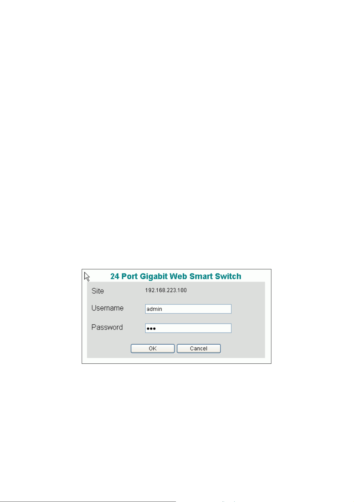
The login dialog box (shown as below) will show up first when the switch’s IP address is entered in
your browser.
Use the default username and password shown as below to complete the login procedure:
Username: admin
Password: 123
This username/password can be modified later for your needs.
6
Page 8
1.2 Configuration Functions for the Switch
After the login is successfully validated, the switch’s home page – System page will show up. The
left part on the page provides the function menus (shown as below) to activate to the individual
configuration page.
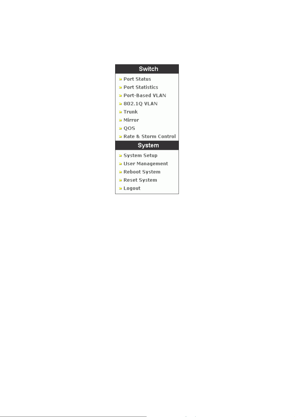
The function menus contain two parts: Switch for setting up the switch functions and System for
maintaining the system parameters.
Switch functions contain:
Port Status – to show port link status and configure port parameters
Port Statistics – to show packet statistic results passed through each port
Port-based VLAN – to setup the port-based VLAN
802.1Q VLAN – to configure the tag-based VLAN
Trunk – to build up the trunk function
Mirror – to setup the port mirroring function
QOS – to configure the Quality of Service function
Rate & Storm Control – to limit the traffic rate and suppress the broadcast storm
System functions contain:
System Setup – to configure the required system information (such as IP address, etc.)
User Management – to maintain the login information to access the switch
Reboot System – to reboot the switch without writing default configurations
Reset System – to reboot the switch after writing default configurations
Logout – to log off the system
7
Page 9
2 Configurations
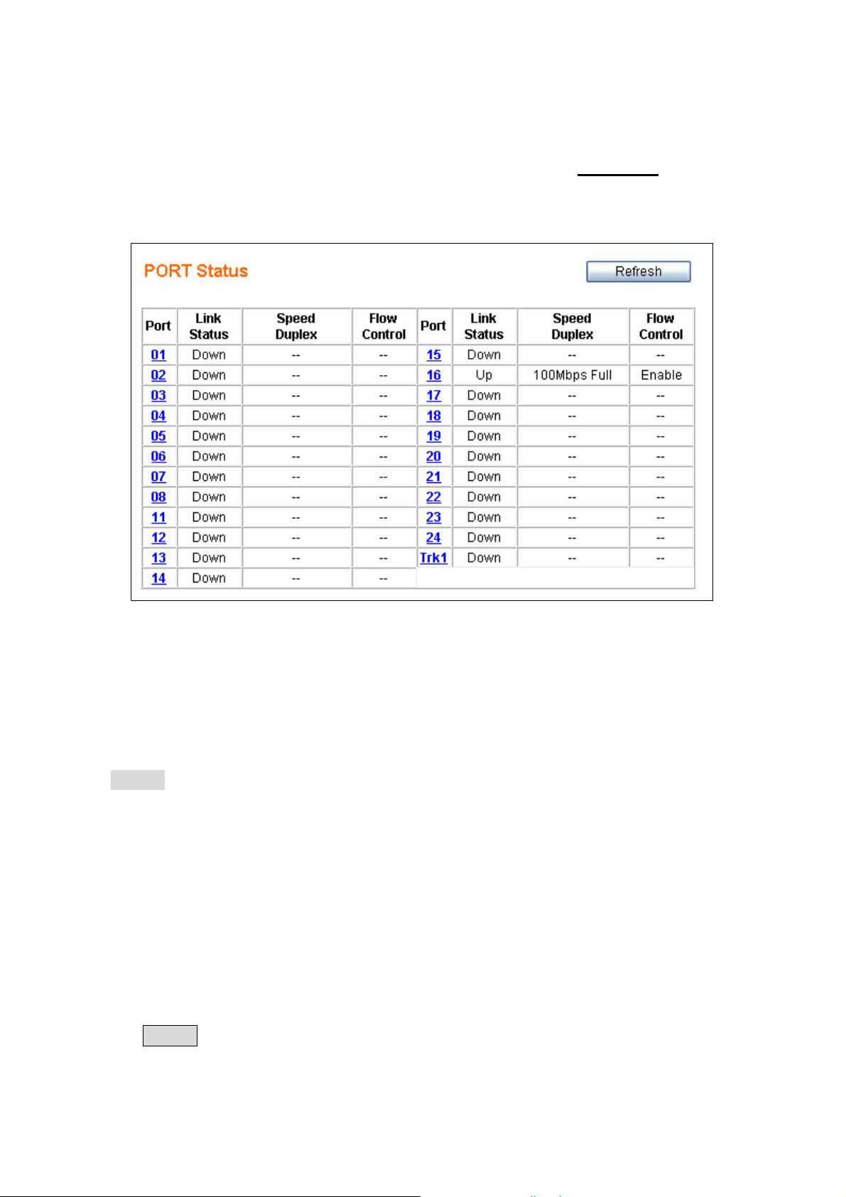
2.1 Port Status
This page provides the current link status for all ports. You can select the Port Status menu to
activate this page and to refresh the current port status.
This page provides the following information:
Port – to specify a port on the switch
Link Status – to show the port link status: Up / Down
Speed / Duplex – to show the current link speed (1G / 100M / 10M bps) and duplex mode
(Full / Half) while the port is linkup.
NOTE: Only the full duplex mode is supported while the link speed is 1Gbps.
Flow Control – to show the flow control capability is Enable / Disable for this port.
The status for the two columns: Speed/Duplex and Flow Control won’t show up while the port link
is down. (The sign ‘-‘ represents the status is unavailable to display.)
If any trunk group is setup, a trunk group can be regarded as one logical port (e.g. Trk1 in the above
figure is grouped by Port9 & Port10) which will show up just like the others. All the trunk member
ports won’t be displayed. Section 2.7 (Trunk) describes port trunking in detail.
Click the Refresh button to manually get the most current link status for all ports.
8
Page 10

2.2 Port Configuration
If you need to do the port configuration, just select the desired port by clicking the Port number in
the Port Status page. Then the Port Configuration page (shown as below) for the selected port will
be opened:
The following parameters will be provided and configured in the Port Configuration page:
Port – the selected port number to be configured (read only)
Admin – to unblock/block the traffic for the port
¾ Disable – to block all traffic for the port
¾ Enable – to enable the bi-directional traffic for the port
(Media --) Auto Negotiation – to enable/disable the capability of auto negotiation for setting
up the link. The options provided for this function depend on the port type – combo ports (Port1
& Port2) shared with fibre media using mini-GBIC interface, or ordinary ports (from Port3 to
Port24) for copper media only.
z 2 Options for combo ports (Port1 and Port2)
9 Fibre – Disable , Copper – Enable – to enable the copper but disable the fibre media
9 Fibre –Enable, Copper –Enable – to enable both media
NOTE: Only the Enable option is provided for copper media in combo ports. Force mode
(i.e. auto negotiation is disabled) is not supported for copper media in combo ports.
z 2 Options for ordinary ports (Port3 to Port24, copper media only)
9 Disable – to disable for this port (force mode)
9 Enable – to enable for this port (auto mode)
The following figure shows the port configuration page for a combo port. (e.g. Port1)
9
Page 11

Speed / Duplex – to setup the link speed and duplex mode in force mode
The options for this function can be selected only when the Auto Negotiation is Disabled (in
force mode) for copper media. There are 4 options for this parameter:
¾ 100Mbps Full – to set the speed 100Mbps in full duplex mode
¾ 100Mbps Half – to set the speed 100Mbps in half duplex mode
¾ 10Mbps Full – to set the speed 10Mbps in full duplex mode
¾ 10Mbps Half – to set the speed 10Mbps in half duplex mode
NOTE: Only full duplex mode is supported for 1Gbps link speed. For copper media, this
system supports the link speed from 10Mbps to 1Gbps for auto mode, and from 10Mbps
to 100Mbps for force mode. For fibre media, only the 1Gbps link speed is supported for
both auto and force mode.
Flow Control – to enable/disable flow control function
¾ Disable -- to disable for the port
¾ Enable – to enable for the port
Default Priority – to setup the priority of frames which will be referenced in QOS function
¾ 0 – 7 – to set the priority level (range = 0 ~ 7)
Security – to enable/disable port security function
If the per-port security is enabled and if a received frame contains a source MAC address that
has already been learned in another port’s address table but not aged out, then the frame is
dropped. Otherwise, the address table entry is updated with the new port’s information and the
entry is updated.
¾ Disable -- to disable port security
¾ Enable – to enable port security
Jumbo Frame – to enable/disable jumbo frame function
If the per-port jumbo frame feature is enabled, the maximum frame size is 9216 bytes. In 100
Mbps mode, the maximum jumbo frame size supported is 9000 bytes
¾ Disable -- to disable jumbo frame support
¾ Enable – to enable jum bo frame support
After the desired options are selected for the above functions, click the Apply button to save the
current settings to the switch and go back to the Port Status Page. Click the Cancel button to go
back to Port Status page.
10
Page 12

2.3 About the Copper/Fibre Media Auto-Detection
This switch provides an option to use either copper or fibre media for the first two combo ports -
Port1 and Port2. This means that you can setup the link by using either copper media to plug-in to
the copper port or use fibre media to plug-in the mini-GBIC port. This switch will automatically
detect which media is plugged into the port. If both copper and fibre media are plugged in the fibre
media has higher priority than the copper to setup the link; the link on the copper media will
be down. The link for the copper media will be re-setup after the fibre media is un-plugged. The
Port Status page will show the current link status according to the active media linking.
NOTE: The link status will take 10 seconds to be stable after any port mode changing (copper /
fibre media switching or auto / force mode changing for fibre media.) for combo ports.
11
Page 13
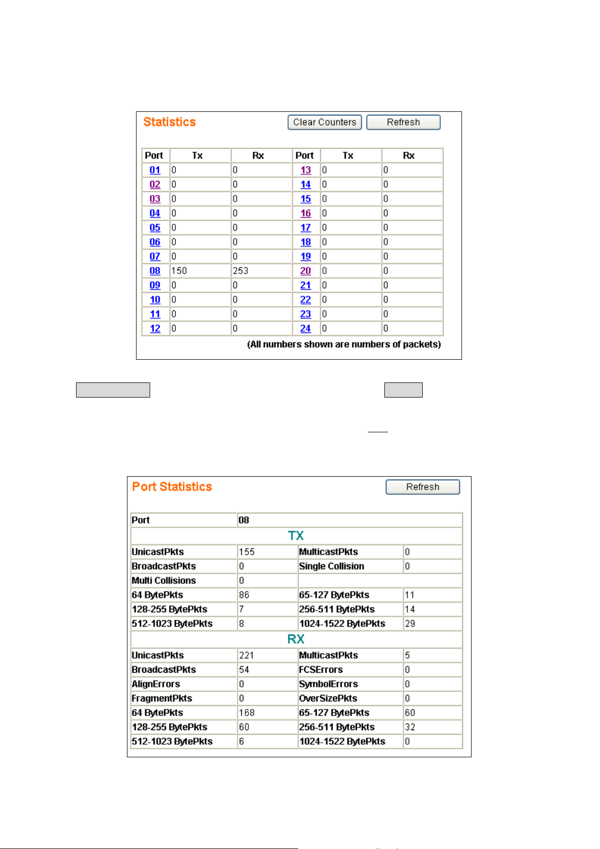
2.4 Port Statistics
The Port Statistics function lets you see the TX/RX packets through each port.
The Clear Counters button will clear all packet counters to 0. The Refresh button will get port
statistics again.
You can check each ports statistics more precisely. Just click the Port number to see the detailed
information.
12
Page 14

The table shown below has the description for each column.
UnicastPkts
MulticastPkts
BroadcastPkts
Single Collision
Multi Collisions
64 BytePkts
65-127 BytePkts
128-255 BytePkts
256-511 BytePkts
512-1023 BytePkts
1024-1522 BytePkts
Number of good unicast packets transmitted.
Number of good multicast packets transmitted.
Number of good broadcast packets transmitted.
Number of packets in which the transmission experienced one collision
Number of packets in which the transmission experienced over two collisions
Number of packets(including bad ones) transmitted that were 64 Bytes in
length
Number of packets(including bad ones) transmitted that were 65-127 Bytes
in length
Number of packets(including bad ones) transmitted that were 128-255 Bytes
in length
Number of packets(including bad ones) transmitted that were 256-511 Bytes
in length
Number of packets(including bad ones) transmitted that were 512-1023
Bytes in length
Number of Non-Jumbo packets(including bad ones) transmitted that were
FCSErrors
AlignErrors
SymbolErrors
FragmentPkts
OverSizePkts
1024-1522 Bytes in length
Number of packets received of proper-size with CRC error and integral
octets
Number of packets received of proper-size with CRC error and non-integral
octets
Number of packets received of proper-size that experienced symbol error
during reception
Number of packets received that were less than 64 bytes without CRC or
alignment error
Number of packets received that were greater than the maximum length
without CRC or alignment error
13
Page 15
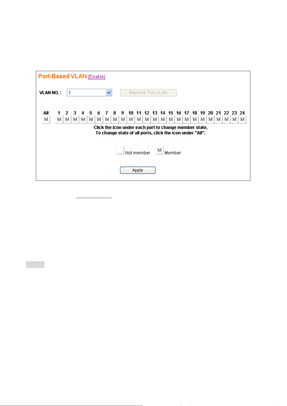
2.5 Port-Based VLAN
The port-based VLAN divides the ports into different Virtual LAN domain groups. After setting the
port-based VLAN, the different VLAN groups can’t access each other. The VLAN initial setting
page is shown as below:
You need to click the
port-based VLAN is enabled, the 802.1Q VLAN will be disabled automatically. The port-based
VLAN and 802.1Q VLAN cannot co-exist at the same time.
You can add, delete, and modify the port-based VLAN for your needs. This system supports up to
32 port-based VLAN groups for manual entry. The following pages will describe in detail how to
configure the port-based VLAN.
NOTE: A default port-based VLAN entry (No=1) is initially created by the system. This VLAN
entry contains members for all ports. It can be regarded as no VLAN function because all
ports are in the same group and no traffic isolation between any two ports. If there are new
port-based VLAN groups cr eated, the VLAN No. 1 will contain no members. The group No. 1
is a read-only VLAN group. And there are only 2 situations for this VLAN – all ports are
member ports, and all ports are not member ports.
Enable/Disable link text to enable/disable the port-based VLAN. When
14
Page 16
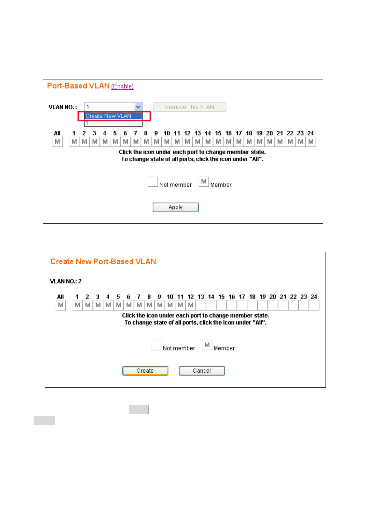
2.5.1 Add Port-Based VLAN Groups
To add a port-based VLAN group, select the Create New VLAN in the VLAN NO dropdown of the
Port-Based VLAN page shown as below:
After selecting the Create New VLAN, the page will be changed like this:
In the above page, VLAN NO will auto setup. Users just need to set VLAN Port Members. After the
settings are complete, press the Create button to go back to the VLAN initial setting page. The
Cancel button lets the user give up the settings and go back to the VLAN initial setting page.
15
Page 17
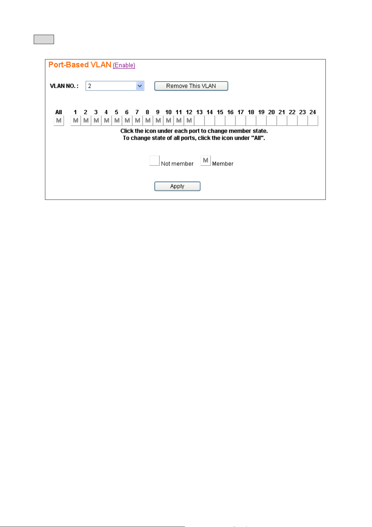
Below is the example page when the user sets Port1-12 to the VLAN Group2 after clicking the
Create button. Now there is a VLAN group No.2 created with the member Port1-12.
While the group No.2 is created, all the members in group No.1 are removed to operate the VLAN
function.
16
Page 18
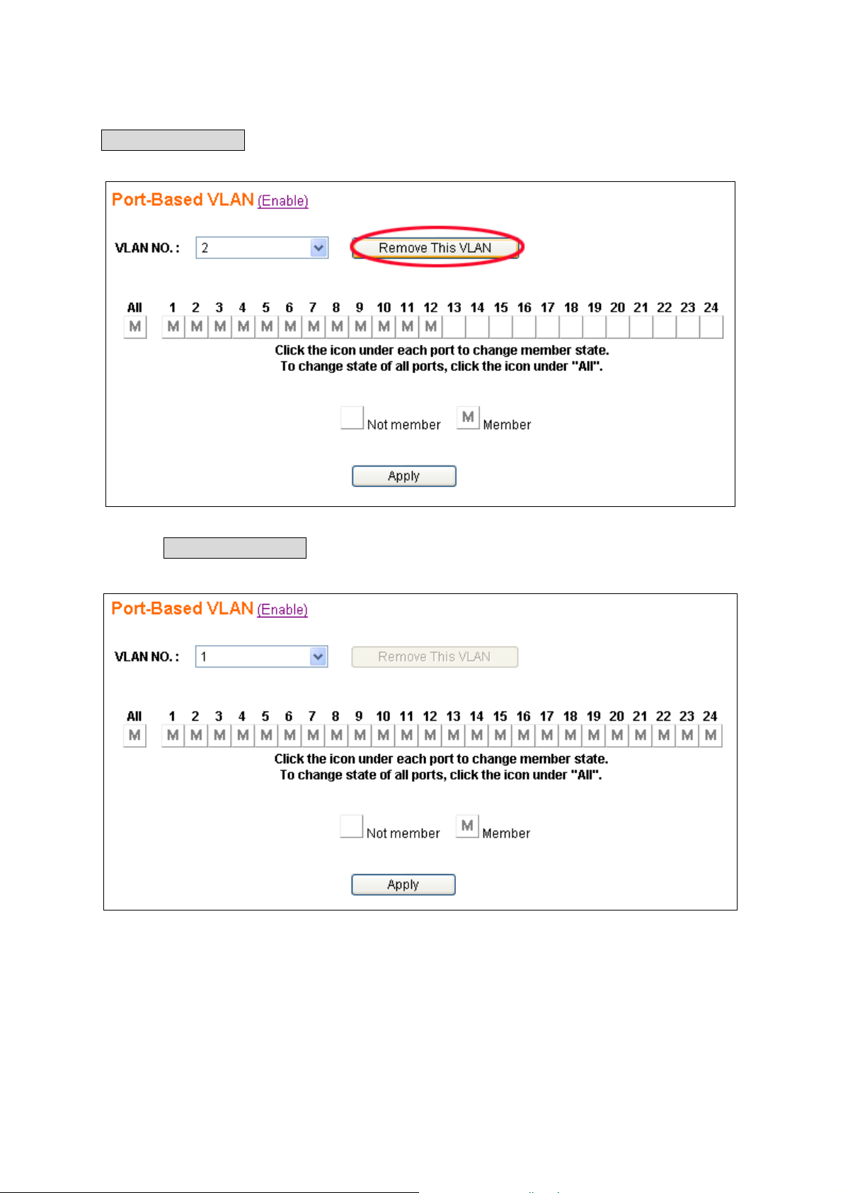
2.5.2 Delete Port-Based VLAN Groups
To delete a port-based VLAN group, just select a desired group (e.g. No.2) to be removed and click
the Remove This VLAN button.
Pressing the Remove This VLAN button results in the following:
Now all ports are set to the members in VLAN group No.1.
17
Page 19
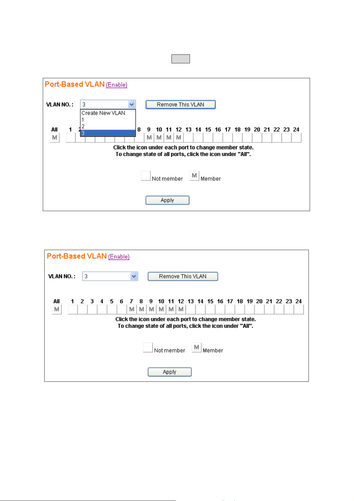
2.5.3 Edit Port-Based VLAN Groups
To edit the current port-based VLAN group, first select the group (e.g. group No. 3) you want to edit
(to add Port7 & Port8 as members) and click the Apply button to activate the setting.
The following figure shows the configuration for the selected group (e.g. No.3).
18
Page 20

2.6 802.1Q VLAN
IEEE 802.1q (tag-based) VLAN can add or strip the 802.1q tag depending on the requirements of the
individual transmitting port. Click the
configurations.
VLAN ID 1 is the default 802.1Q VLAN. VLAN ID 1 cannot be deleted. However, the VLAN ID 1
group member can be changed.
Incorrect 802.1Q VLAN settings will cause the web access to fail to connect. You can use the CLI
(Command Line Interface) to recover. The detailed CLI operating guide will be discussed in section
2.14.
Here is a simple way to recover the web access to the switch.
1. In CLI, type VE to disable 802.1Q VLAN
2. Go to 802.1Q VLAN web interface. Set the default VLAN ID 1 group member(01-24) to U
3. Go back to CLI mode, type VV to set Admin PVID (port no.=25) to 1.
4. In CLI mode, type VE to enable 802.1Q VLAN. You can access the web in the 802.1Q VLAN
enable environment now.
802.1Q VLAN menu to activate the following pages to do the
Currently this system supports up to 32 tag-based VLAN groups for manual entry. The following
pages will describe in detail how to do these configurations.
19
Page 21

2.6.1 Enable/Disable VLAN
In the 802.1Q VLAN page you can enable/disable the tag-based VLAN function by clicking
(Enable) or (Disable) besides the page header:
¾ Enable – to activate the tag-based VLAN function (port-based VLAN function will
automatically be disabled).
¾ Disable – to de-activate the tag-based VLAN function, even though there are some VLAN
entries created. (i.e. any tag-based VLAN entry is still retained although tag-based VLAN
function is disabled. Port-based VLAN function will be auto enabled.)
20
Page 22

2.6.2 802.1Q VLAN Port Configuration
Click the Port number to enter the port configuration page for 802.1q VLAN.
The following figure shows the 802.1Q VLAN Port Configuration page by port. (e.g. Port10)
You can set the individual port for configuring the 802.1q settings in the following fields:
¾ PVID – enter a valid VLAN ID(1-4094), and PVID must be one of the existing VLAN group
ID.
¾ UnTag Frame – Accept or drop incoming untag frames.
¾ Tag Frame – Accept or drop incoming tag frames.
Finally, there are 2 buttons to select:
Apply: To submit the port configuration settings to the switch.
Back: To go back to the 802.1q main setting page.
21
Page 23

2.6.3 802.1Q VLAN Config
The following figure is the page to add/delete/edit the 802.1q VLAN entry. Each VLAN entry has 3
parameters, VID, Tag Members and UnTag Members to be assigned.
After selecting Create New VLAN the figure shown as below will be displayed:
¾ VID – a unique VLAN ID. The range is from 1 to 4094
¾ Tag Members & UnTag Members – Click the image directly, it will switch to Not Mem ber,
Tag Member or Untag Member.
Input the VID (1-4094) and check the member row to select the ports which belong to this VLAN
group. After these settings are complete click the Create button to submit the data to the switch.
Click the Cancel button to abort the actions and go back to the VLAN Config page.
22
Page 24

Here is an example of how to configure the 802.1q VLAN. There are four existing 802.1q VLAN
entries as shown below.
You can delete the 802.1q VLAN entry. Click a radio button on the Select column to select the entry
to be deleted (e.g. VID = 200), then click the Remove This VLAN button to do the deletion.
After the action mentioned above, the 802.1q VLAN table will be changed like this:
The VID entry (VID=200) is successfully deleted.
23
Page 25

If you would like to edit the parameters of an 802.1q VLAN, just select a VID to be changed (e.g.
VID =300) then click the Apply button to do the modifications: Port 17 and Port18 are selected to be
the tag members of this group.
Finally, click the Apply button to do the changes.
24
Page 26

2.7 Trunk
This 24G web smart switch supports MAC-based trunking, which allows more than one port to be
grouped together as a single link connection between two switch devices. This is also useful for
switch-to-server and switch-to-router applications. The 24G web smart switch allows four trunk
groups that can accommodate up to eight trunk members. A port in one trunk group cannot be a
member of another trunk simultaneously. This feature provides redundancy and increases the
effective bandwidth through a link. The traffic patterns can be more balanced between the ports
within a trunk group by dynamically performing the MAC-based algorithm. It is supported only on
point-to-point links with MACs operating in full duplex mode. All links in the same trunk group
must operate at the same rate.
The 24G web smart switch provides dynamic failover when trunking is enabled. If a port in the trunk
group fails, the other ports of the trunk group assume traffic designated automatically for the trunk.
The links within the trunk group should have an equal amount of traffic. To achieve this, the switch
performs load balancing based on a distribution algorithm.
The following parameters are required to be set:
Distribution Criterion – chooses the distribution algorithm with which the switch performs
load balancing based on:
¾ SA (Source MAC Address)
¾ DA (Destination MAC Address)
¾ SA + DA (both SA and DA)
Member – the member port(s) of trunk group(s)
Select the
Trunk menu on the web page to activate the page shown as below.
25
Page 27

Because a trunk port can be aggregated by the member ports with the same configurations in most
functions for each other, there are some rules to limit the configurations of the trunking. The
following section will list the related rules for this function.
26
Page 28

2.7.1 Trunking Rules
The following rules will limit the configurations for port trunking:
The attributes of all trunk member ports in Port Configuration, Mirror, Rate Control, 802.1Q
VLAN and Port-Based VLAN functions must be the same.
All trunk member ports can not be a capture port or monitored port in Mirror function.
If Port1/Port2 using the fibre media wants to be grouped with the ports using pure copper
(Port3 – Port24) as a trunk port, the auto negotiation option must be set to Enable for all
member ports. If both Port1 & Port2 are the only trunk member ports and they are using fibre
media, the auto negotiation option can be Enable or Disable.
After enabling a trunk group, a new trunk port will be created in the port list. For example,
Port2, Port4, and Port6 belong to Trunk 1. Check the other page (Port Status) with port list,
Trk1 port will be added after all normal ports. The member ports of this trunk group will
disappear.
27
Page 29

When the enabled trunk group is set to disabled, all trunk member ports will be released to
ordinary ports and their functions can be configured individually. At that moment, their
configuration attributes will be retained to the last settings while they were member ports of the
trunk group. The following 3 figures show how the port configurations (e.g. Port6) will be
retained before and after the trunk (e.g. Trk1) is disabled.
28
Page 30

2.7.2 Get/Refresh the Latest Trunk Settings
Click the Trunk menu on the web page, the latest trunk settings on the switch will be displayed.
This is also the page to configure the trunk function.
29
Page 31

2.7.3 Enable Trunk
¾ Step 1: Choose the Distribution Criterion.
¾ Step 2: Choose the member port(s) up to 8 ports for each trunk group.
¾ Step 3: Click the Apply button to enable trunk settings.
30
Page 32

2.7.4 Modify T runk Settings
¾ Step 1: Choose the Distribution Criterion.
¾ Step 2: Choose the member port(s) up to 8 ports for each trunk group.
¾ Step 3: Click the Apply button to modify trunk settings.
31
Page 33

2.7.5 Disable T runk
¾ Step 1: Click the Not Trunking.
¾ Step 2: Click the Apply button to disable trunk.
32
Page 34

2.8 Port Mirroring
Port mirroring allows ingress and/or egress traffic to be monitored by a single port. The single port is
mirror capture port. The 24G web smart switch can be configured to mirror the ingress and/or egress
traffic of another port. Port monitoring is independent of L2 switching. The networking manager can
monitor all traffic sent/received through the 24G web smart switch.
Select the
Mirror menu on the web page to activate the configuration page.
33
Page 35

2.8.1 Get/Refresh the Latest Mirror Settings
Click the Mirror menu on the web page. The mirror settings on the switch will be displayed. This is
also the page to configure the port mirroring function.
The following parameters are required to be set:
Mirroring Options – There are four options for each port:
¾ Disable Mirror – to disable mirror function.
¾ Mirr or All Frames – to set the corresponsive port to be a monitored port to investigate
bi-directional traffic.
¾ Mirror Incoming Frames – to set the corresponsive port to be a monitored port to
investigate only ingress (receiving, Rx) traffic.
¾ Mirror Outgoing Frames – to set the corresponsive port to be a monitored port to
investigate only egress (forwarding, Tx) traffic.
Monitored Port – The port which is monitored.
Capture Port – All traffic mirrored from the monitored port are received on the capture port.
34
Page 36

2.8.2 Enable Mirror
¾ Step 1: Choose Mirror option to be Mirror All Frames.
¾ Step 2: Choose the Monitored Port to be Port16.
¾ Step 3: Choose the Capture Port to be Port8.
¾ Step 4: Click the Apply button to enable mirroring settings.
35
Page 37

2.8.3 Modify Mirror Settings
¾ Step 1: Change Mirror option to be Mirror Outgoing Frames.
¾ Step 2: Change the Monitored Port to be Port3
¾ Step 3: Change the Capture Port to be Port22.
¾ Step 4: Click the Apply button to modify mirroring settings.
36
Page 38

2.8.4 Disable Mirror
¾ Step 1: Choose Mirror option to be Disable Mirror.
¾ Step 2: Click the Apply button to disable mirroring.
37
Page 39

2.9 QOS (Quality of Service)
The 24G web smart switch provides up to four internal transmit queues per port to support four
different traffic priorities . The high-priority traffic experiences less delay in the switch than that of
lower priority traffic under congested conditions. The 24G web smart switch provides three types of
QOS. It can assign the packet to one of four transmit queues according to 802.1P QOS. If the
incoming packet is untagged, the 24G web smart switch uses the priority field in the per-port
Default Priority in the Port Config page to assign the packet to one of four transmit queues. If the
incoming packet is tagged or priority tagged, the 24G web smart switch uses the priority field in the
incoming packet tag to assign the packet to one of four transmit queues.
The 24G web smart switch also provides a remap function. This switch always inserts the packet into
the Tx Queue by priority ID. Users can assign the map between priority and queues. This switch
handles the packets transmit by the Tx Queue Weight Setting when the Weighted Round-Robin
algorithm is selected.
Select the
QOS menu on the web page to activate the page shown as below.
38
Page 40

2.9.1 Get/Refresh the Latest QOS Settings
Click the QOS menu on the web page. The QOS settings on the switch will be displayed. This is
also the page to configure QOS.
The following parameters are provided to be set:
Scheduling Method
¾ Strict Priority – to set this switch to transmit packets with Strict Priority algorithm
¾ Weighted Round Robin – to set this switch to transmit packets with Weighted Round
Robin algorithm
Priority/Queue Map
¾ To set the Priority and Queue map.
Weight
¾ To set the weight for every transmit queue. (Weight range: 1 ~ 15)
¾ The weight of higher queue should not be less than the lower queue.
39
Page 41

2.9.2 Enable QOS
¾ Step 1: Choose the Scheduling Method (ex: Weighted Round Robin).
¾ Step 2: Set Priority/Queue map (ex: Priority1, 2, 3 and 4 belong to Queue0, Priority4 and 5
belong to Queue1, Priority6 belong to Queue2, Priority7 belong to Queue4).
¾ Step 3: If Scheduling Method is Weighted Round Robin, assign a weight for every transmit
queue (ex: Queue0 weight = 1, Queue1 weight = 3, Queue2 weight = 5, Queue3 weight = 7).
¾ Step 4: Click the Apply button to enable QOS settings.
40
Page 42

2.9.3 Modify QOS Settings
¾ Step 1: Change the Scheduling Method to be Strict Priority.
¾ Step 2: Change the Priority/Queue map (ex: Prirotiy0 belong to Queue3, Priority1, 2 and 3
belong to Queue2, Priority4, 5 and 6 belong to Queue1, and Priority7 belongs to Queue0).
¾ Step 3: Click the Apply button to modify QOS settings.
41
Page 43

2.10 Rate and Storm Control
To provide more efficient system performance, the 24G web smart switch provides rate and storm
control to limit the per-port traffic rate and to globally suppress the storm from unknown or
broadcast frames received by the system.
2.10.1 Rate Control
This system supports per-port rate control. When the incoming frame rate of a particular port
exceeds a selected rate, the excess frame traffic is subject to packet drops or flow control.
Click the
configure this function.
Rate & Storm Control submenu to open the Rate Limit and Storm Control page to
42
Page 44

Select port number to setup the per-port rate control value. In the page of ingress rate limit, shown in
the following figure (e.g. for Port2), select one (e.g. 8Mbps) of 14 different rates to limit the rate or
select “No Limit” to un-limit the rate for this port.
After clicking the Apply button to activate the setting, the previous page will be reappear and show
the latest setting.
43
Page 45

2.10.2 Storm Control
In the Rate Limit and Storm Control page, the hyperlink (e.g. Disabled) on the row with Storm
Control field shows the current setting of this function. This function will globally affect all ports in
the system. Just click this hyperlink to configure the setting.
In the Storm Control page, there are 2 fields to configure this function:
Storm Control Type – 5 options to provide in this dropdown
¾ Disabled – to disable storm control. This option will disable the dropdown in the Storm
Control Rate field
¾ Broadcast only – to suppress the broadcast frames only
¾ Broadcast and multicast – to suppress both the broadcast and multicast frames
¾ Broadcast and unknown unicast – to suppress both the broadcast and unicast frames
with unknown destination MAC address
¾ Broadcast, multicast and unicast – to suppress broadcast, multicast and unicast frames
with unknown destination MAC address
The following figure shows the options in the dropdown box of the Storm Control Type field.
44
Page 46

Storm Control Rate – this field provides 13 different control rates from 1fps (frames per
second) to 15,000fps. This dropdown will be disabled while the Storm Control Type is
disabled.
After selecting the storm control type and rate, click the Apply button to activate the settings for this
function. The figure shown as below is an example of storm control configuration with type of
broadcast only and limited rate of 15fps.
45
Page 47

2.11 System Setup
The System Setup page provides the management information of the switch. This page, shown as
below, can be activated by clicking the System Setup menu under the System section.
The following parameters can be configured / displayed:
Model Name – the model name of this switch (read-only)
Chip Version – the switch chip version of this switch (read-only)
Firmware Version – the current version of the firmware existing on the switch (read-only)
DHCP Client – DHCP client status
IP Address – the IP address to manage this switch through the configuration port.
Subnet mask – the network mask to identify the sub-network address
Gateway – the IP address of the default gateway to reach to the outside network
MAC address – the MAC address for the configuration port interface (read-only)
ARL Aging – the aging time of dynamic ARL entry in address table
46
Page 48

2.11.1 Firmware Update
The 24G web smart switch provides the facility to update firmware for new features, customized
requests and system fault recovery. The page, shown as below, can be activated by clicking the
Update link on the System Setup page.
This system supports both BOOTP/TFTP and pure TFTP to update the firmware. The TFTP server
IP address and firmware filename needs to be correctly provided to the switch to start the firmware
updating if the pure TFTP way, is selected. Using the BOOTP/TFTP it is much easier to do the
firmware updating because no parameters need to be input if the BOOTP/TFTP server is correctly
setup.
47
Page 49

2.11.1.1 Firmware Update Via TFTP
Before proceeding with the firmware update, it is required to correctly prepare the TFTP server and
the firmware file which will be uploaded to the switch. (Please refer to the vendor’s instruction
guide for setting up the TFTP server you would like to use).
When the TFTP server and the firmware file are ready, please enter the TFTP server IP address and
firmware filename. Click the Apply button to start the firmware update through the any front port on
the switch.
The time taken for processing the firmware update will be approximately 50 seconds.
NOTE: If the switch can not connect to the TFTP server, click the Cancel button to stop the
firmware update process.
48
Page 50

2.11.1.2 Firmware Update Via BOOTP/TFTP
Before proceeding with the firmware update, it is required to correctly prepare the BOOTP/TFTP
server and the firmware file which will be uploaded to the switch. (Please refer to the vendor’s
instruction guide for setting up the TFTP server you would like to use).
When the BOOTP/TFTP server and the firmware file are ready, click the Apply button to start the
firmware update through the any front port on the switch.
The time taken for processing the firmware update will be approximately 55 seconds.
49
Page 51

2.11.2 DHCP Client
The IP address of the 24G web smart switch can be statically assigned by manual entry or
dynamically assigned by a DHCP server.
2.11.2.1 Assign a fixed IP address
Change DHCP Client to be disabled. Enter a fixed IP address, Subnet mask and Gateway, and then
click the Apply button.
2.11.2.2 Assign an IP address by DHCP server
Change DHCP Client to be enabled. The system’s IP address, subnet mask and gateway address will
be assigned and changed immediately by the DHCP server. It may lose the web connection because
of the changing of the system’s IP. Use the console port to get the most current network
configurations after enabling the DHCP function.
The IP address, Subnet mask and Gateway fields will be disabled (read-only) while the DHCP
client is set to Enabled.
50
Page 52

2.11.3 ARL Aging
The 24G web smart switch supports aging timer for MAC address entry in the address table. If ARL
aging is enabled and aging time is 300 seconds, every MAC address entry learned from every front
port will stay in the address table for 300 seconds. After 300 seconds, the switch will remove this
MAC entry.
ARL Aging to modify aging time settings. Check the Enable ARL Aging checkbox to enable
Click
it. Uncheck Enable ARL Aging to disable it. Enter aging timer and click the Apply button to set
aging time.
51
Page 53

2.12 User Management
User management is used for maintaining the username and password for login validation to access
the switch. This switch provides one login account for configuration management. Just click the
User Management menu to activate the User Management page as shown below:
New Username – to set the username string (max. 10 characters)
New Password – to set the password string (max. 10 characters)
Retype Password – to confirm the password string (max 10 characters)
52
Page 54

2.13 Reset System
This switch can be rebooted or reset to default configurations through the web page.
Reboot System menu to reboot the system.
Click
Reset System menu to reset the system back to factory settings.
Click
¾ Reboot System – Just reboot the system. All configuration settings will be retained to the latest
changes before the reboot procedure. If you want to keep your configuration, select this option.
¾ Reset System – Reset all configurations (including the username, password and IP address;
only the MAC address won’t be changed) to default settings before rebooting the system. This
means that any customized configurations will be lost and can’t be recovered.
The 24G web smart switch also provides an alternative to the Reset System option by using the
Reset button
¾ While the system is running (the DIAG LED indicator is ON), pressing and holding the Reset
button (for over 5 seconds) until the DIAG LED indicator stars to flash will activate the
Write Default procedure.
After the procedure mentioned above is done, the switch will be automatically rebooted and
initialized using the default settings. .
System rebooting will take about 10 seconds. You need to login to the system again to enter the web
pages for continuous configurations.
on the rear panel:
53
Page 55

2.14 Command Line Interface (CLI)
In addition to the web management, the 24G web smart switch also provides a serial interface
(RS-232) as a console port on the rear panel to manage the switch for system setup, user
management, reset system and firmware updates through the command line interface (CLI). We
recommend you use Windows Hyper Terminal. This section will show you how to setup and use
Hyper Terminal to manage this switch.
2.14.1 Hyper Terminal Setup Options
Baud Rate:19200 bps
Data Bits:8
Parity:None
Stop bits:1
Flow control:None
2.14.2 Switch Management Commands In Console
Login System
After the system has started, the following prompt will be displayed in Hyper Terminal.
The user needs a valid username and password to login to this system. The username and
password in CLI are the same as the ones used for login access through the web page.
Please enter the correct username now.
After entering the username, the following prompt will be displayed. The user should enter
the correct password now, and then begin to manage the 24G web smart switch.
54
Page 56

Help Menu
Press “H”, “h” or “?” to show all management commands in the console.
Get System Information
Press “IG” or “ig” to show model name and firmware version.
Get Current Network Settings
Press “NG” or “ng” to show DHCP client status, system IP address, network mask,
gateway and MAC address.
55
Page 57

Configure Network
Press “NS” or “ns” to configure system network.
If the user wants to assign this system an IP address by DHCP server, enter “Y” or “y” to
start DHCP progress. .
If the user wants to assign this system a fixed IP address manually, please enter “N” or “n”
to abort DHCP progress.
User Management
Type “UM” or “um” to configure the account and password which is used to login to this
system. Enter a new username and password. After confirming the password, the system
will ask user to re-login.
56
Page 58

Enable/Disable 802.1Q VLAN
Type “VE” or “ve” to enable or disable the 802.1Q VLAN function.
Get 802.1Q VLAN Enable Setting
Type “VF” or “vf” to show if 802.1Q VLAN function is enabled or disabled.
Set PVID
Type “VV” or “vv” to set per-port PVID in 802.1Q VLAN function. The PVID of admin
port (port 25) in 802.1Q VLAN function also can be modified. The PVID which the user
wants to set must be one of the existing VLAN group ID.
The Admin port is the port you use to manage the switch function. The Default Admin
PVID is 1.
Get PVID
Type “VP” or “vp” to show per-port PVID in 802.1Q VLAN function. The PVID of admin
port (port 25) in 802.1Q VLAN function can also be shown.
57
Page 59

Upgrade Firmware Via TFTP or BOOTP/TFTP
Type “UF” or “uf” to start the firmware upgrade progress via TFTP server.
Choose “1” to update firmware via TFTP. Enter the TFTP server IP address and firmware
filename.
Choose “2” to update the firmware via BOOTP/TFTP.
Once the 24G web smart switch has rebooted, the firmware upgrade progress has finished
correctly. Type “IG” or “ig” to check the firmware version after login.
Reboot System
Type “RB” or “rb” to restart the system.
58
Page 60

Reboot System After Write Default
Type “RD” or “rd” to reset the system to factory settings.
Logout
Type “LO” or “lo” to logout of the system.
59
Page 61

3 Specifications
Standards Compliance
IEEE 802.3 10BaseT Ethernet
IEEE 802.3u 100BaseTX Fast Ethernet
IEEE 802.3ab 1000Base Gigabit Ethernet
IEEE 802.3x flow control for half and full duplex
IEEE 802.1q Tag-based VLAN
Interfaces
24 x 1000BaseTX RJ-45 connector ports,
2 mini-GBIC ports
1 RS-232 terminal port
Buffer Memory
512MB for packet buffers
8K entries for MAC
4K entries for VLAN
Packet Forwarding and Filtering Rates
1Gbps Ethernet: 1,488,000 packets per second per port
100Mbps Ethernet: 148,800 packets per second per port
10Mbps Ethernet: 14,880 packets per second per port
Environment
Operation temperature: 5 to 45 centigrade
Operating humidity: 10%-90%, non-condensing
Storage temperature: -20 to 70 centigrade
LED Panel Display
1 power LED: Green (normal)
1 Diagnostics LED: Green (normal), Blinking (reset configuration)
Port LEDs: Port1 – 24, left corner of each RJ-45 port, Green (link ok), Blinking (activity)
Speed LEDs: Port1 – 24, right corner of each RJ-45 port, Green (1Gbps), Off (10Mbps or
100Mbps)
Fibre LEDs: Port1 – 2, Green (link ok), Blinking (activity)
60
Page 62

Power
Input: 100-240VAC, 50/60Hz
Power consumption: 40 Watts max.
Dimensions
440mm (W) × 184mm (D) × 44mm (H)
Weight
2.3 Kg
Electromagnetic Emissions: Class A
FCC, CE, VCCI, C-Tick
Safety
CB
61
Page 63

CE Conformity
This equipment has been tested and found to comply with the relevant European Community
Directive 93/68/EEC for Electromagnetic Compatibility for Information Technology Equipment.
FCC Warning
This equipment has been tested and found to comply with the limits for a Class A digital device,
pursuant to Part 15 of the FCC Rules. These limits are designed to provide reasonable protection
against harmful interference when the equipment is operated in a commercial environment.
This equipment generates, uses and can radiate radio frequency energy and, if not installed and used
in accordance with the instruction manual, may cause harmful interference to radio communications.
Operation of this equipment in a residential area is likely to cause harmf ul interference in which case
the user will be required to correct the interference at his own expense.
The user is encouraged to try to correct the interference by one or more of the following measures:
• Reorient or relocate the receiving antenna
• Increase the separation between the equipment and receiver
• Connect the equipment into an outlet on a circuit different from that to which the receiver is
connected
• Consult the dealer or an experienced technician for help
LINDY No. 25010
www.lindy.com
62
 Loading...