

Page 1
16 & 24 Port Fast Ethernet
NWAY Switch
User Manual English
LINDY No. 25009, 25017
www.lindy.com
Introduction
Thank you for purchasing the LINDY Fast Ethernet NWAY
Switch. This high performance network switch is ideal for small
networks or for segmenting larger networks into smaller,
connected subnets for improved performance.
All of its ports are capable of 10/100Mbps auto-negotiation, while
the 10/100Mbps auto-sensing ability provides the easiest, most
hassle-free way to integrate older 10Base-T network devices.
This switch delivers a dedicated 10 or 100Mbps connection to
every attached client with no bandwidth congestion issues. It
also supports an auto MDI/MDI-X function - each port can be
used to connect to any other Ethernet device without the need
for crossover cables!
Store-and-forward architecture is used by the switch to filter and
forward data after each packet is received and examined to be
free of errors. All of the ports support full and half-duplex
operation which doubles the network bandwidth and all ows the
simultaneous transmission and reception of frames without
causing collisions.
The ‘Plug & Play’ switch requires no special software to
configure and is fully compliant with the 10Base-T specifications
of the IEEE802.3 Standard and with 100Base-TX specifications
of the IEEE802.3u Standard. Diagnostic LEDs on the front panel
show the operating status of both the switch and the individual
ports.
Packing List
16 or 24 Port 10/100Mbps Fast Ethernet NWAY Switch
1 x power cable
19” Rack mount brackets with screws, rubber feet
This manual
Specifications
Standards: IEEE 802.3 10Base-T, 802.3u 100Base-TX,
IEEE 802.3x Flow Control
Ports: 16 or 24 x RJ-45 10/100Mbps Fast Ethernet
Auto MDI/MDI-X (Auto crossover)
Network speed: 10/100/Mbps & Full/Half-duplex mode auto
detection
Switching Architecture: Store and Forward
MAC Address: 8K
Buffer Memory: 160KB
NWAY Auto-negotiation: All ports
Dimensions: 441 x 130 x 44mm (WxDxH) 24 Port model
Dimensions: 441 x 161 x 44mm (WxDxH) 16 Port model
Power Supply: internal 3.3V, 4A (100 ~ 240V AC, 50 ~ 60
Hz, external)
Operating Temperature: 0-40°C
Operating Humidity: 10-90% (Non-condensing)
For indoor use only
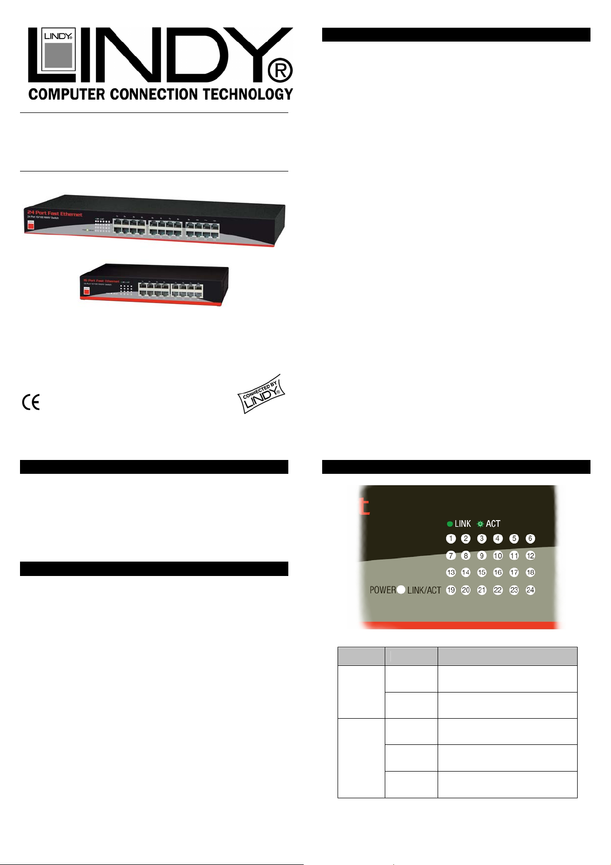
LED Indicators
LED Status Operation
Power
On Power is on
Off Power is off
On The port is connected
Link/Act
Flashing
Off No connection
The port is transmitting or
receiving data
Page 2

Installation
Operating Environment
This switch must be installed and operated within the limits
of the specified operating temperature and humidity (see the
Specifications section)
Do not place objects on top of the unit. Do not obstruct any
vents on the unit
Do not position the switch in direct exposure to the sun, or
near any heat source such as a heater, radiator etc.
Prevent water and moisture entering the unit. If necessary,
use a dehumidifier to reduce humidity.
Connecting network devices
This switch features Auto MDI/MDI-X RJ-45 ports for easy
connection to other network devices using straight-through type
connecting cable. As a minimum, the network patch cables must
at least comply with the Category 5 standard for 10 and
100Mbps data transmission.
1. Connect one end of the network cable to the RJ-45 port on
the switch. Connect the other end to the RJ-45 port on the
network device
2. Follow the same procedure to connect each of the RJ-45
ports on the switch.
3. Please always be aware that the maximum length of any
Ethernet segment is 100m. This can be achieved by using
patch cables of no more then 5m length at both ends plus
an installation cable in between for the remaining length.
Using higher spec network cable can increase this to a
certain extent.
4. Connect the power cable to the mains and to the power
socket on the unit.
Connecting to another network switch
You can use any port to make a connection to another s witch,
with either straight or crossover cable, as all the ports support
Auto MDI/MDI-X.
Rack mounting the switch
The switch can either be installed standalone or mounted in a
19” rack. The switch is supplied with two rack mountin g brackets
and screws for this purpose.
Troubleshooting
The power LED is not lit
Check the power cable is properly connected to both the
mains outlet and the switch
Make sure the power at the mains socket is switched on!
The Link/Act LED is not lit when connected to a network
device
Check the power cable and power switch of the device
connected to the switch. Make sure it is turned on!
Check the network cable. Make sure it is properly
connected to the switch and to the network device. The
segment length has to be below 100 metres (see remark
above) and all cables and connectors should be at least
category 5 compliant.
If this does not solve the problem try another port of the
switch that works OK and also check if the other device
works OK by attaching it to another properly working
network switch
If you experience any other problems with the switch pleas e
contact LINDY or your supplier.
Radio Frequency Energy, Certifications
FCC Warning
This equipment has been tested and found to comply with the limits for a Class A
Digital device, pursuant to part 15 of the FCC Rules. These limits are designed to
provide reasonable protection against harmful interference in a commercial
environment. This equipment generates, uses, and can radiate radio frequency
energy and, if not installed and used in accordance with the instructions, may
cause harmful interference to radio communications.
Operation of this equipment in a residential area is likely to cause harmful
interference in which case the user will be required to correct the interference at his
own expense.
This device complies with Part 15 of the FCC Rules.
Operation is subject to the following two conditions:
(1) this device may not cause harmful interference, and
(2) this device must accept any interference received; including interference that
may cause undesired operation.
LINDY No’s 25009 & 25017
1st Edition November 2005
www.lindy.com
 Loading...