

Page 1

Eight (8)-Port Gigabit Ethernet Switch
USER'S GUIDE
Eight (8)-Port1000BASE-T/100BASE-TX/10BASE-T Gigabit EthernetSwitch
LINDY Part No. 25008
Page 2

T ABLE OF CONTENTS
1 UNPACKING INFORMATION................................................. 3
2 PRODUCT INTRODUCTION..................................................4
2.1 Models..................................................................................... 4
2.2 Key Features............................................................................ 4
2.3 The Front Panel....................................................................... 4
2.3.1 1000BASE-T.................................................................... 4
2.3.2 Cabling............................................................................4
2.3.3 Status LEDs ..................................................................... 5
2.4 The Rear Panel........................................................................ 5
2.4.1 Power Socket...................................................................5
2.4.2 Network Ports.................................................................. 5
2.4.3 Console Port.................................................................... 5
3 INSTALLATION...................................................................... 6
3.1 Rackmount placement.............................................................. 6
4 HELPFUL SUGGESTIONS .................................................... 7
4.1 Priorto Installation.................................................................... 7
4.2 Half-and Full-Duplex................................................................ 7
4.3 Auto-Negotiation....................................................................... 7
4.4 MACAddress Table.................................................................. 7
5 SAMPLE APPLICATION ........................................................ 8
6 SMART FUNCTION CONFIGURA TION..................................9
6.1 HyperTerminal .......................................................................... 9
6.2 System Initiating..................................................................... 10
7 USE FUNCTION MENU........................................................ 11
7.1 Mainmenu ..............................................................................11
7.2 System Configuration..............................................................11
7.3 Port Configuration..................................................................12
7.4 PortTrunkingConfiguration.................................................... 13
7.5 Port Mirroring Configuration.................................................... 14
7.6 VLANConfiguration................................................................ 15
7.7 Priority Configuration.............................................................. 16
7.8 Port Statistics......................................................................... 16
7.9 Restart................................................................................... 17
7.10 Exit........................................................................................ 17
8 PRODUCT SPECIFICATIONS.............................................. 18
2
Page 3
1 UNP ACKING INFORMATION
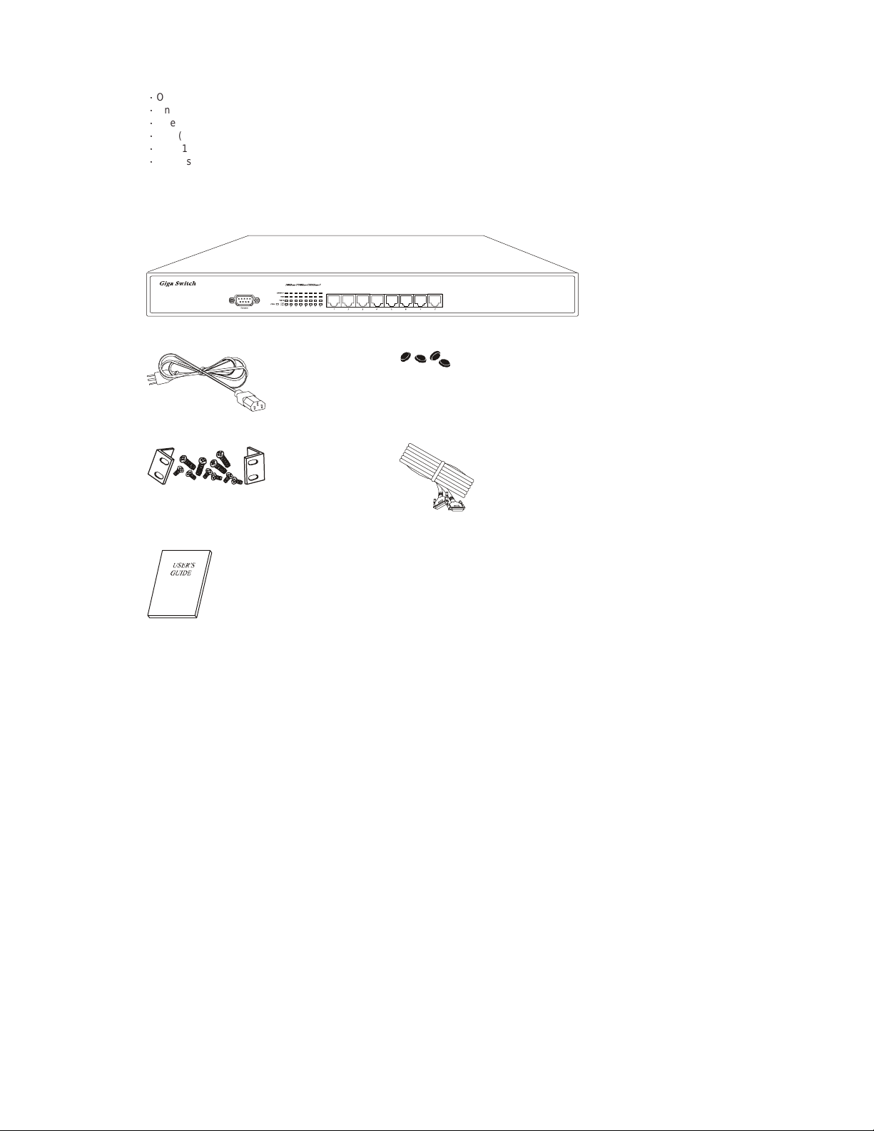
Thank you for purchasingthisSwitch. Before continuing,please check the contents of the productpackage. This product
packageshould contain the followingitems:
ƍ
One(1) GigabitEthernetSwitch.
ƍ
One(1) PowerCord.
ƍ
One(1) Four (4) Rubber Feet.
ƍ
One(1) RackmountKit.
ƍ
One(1) ConsoleCable
ƍ
This User’s Guide.
If anything is missing, please contact your place of purchase immediately.
GigabitEthernet Smart Switch (19 inches case)
PowerCord Four(4) RubberFeet
Rackmount Kit (19 inches case only) Consolecable
User’sGuide
3
Page 4
2 PRODUCT INTRODUCTION
2.1 Models
The switchprovides Eight (8) Gigabit copper ports.Eachport is equipped with 2000 Mbps, Full-Duplex, CollisionFree
Bandwidth. It’s a multi-speed,versatilenetworkdevicethat c ombines Gigabit, FastEthernet, and Ethernet ports in a single
device.
2.2 KeyFeatures
ƍ
Operates at m aximum packet forwardingratein 14880pps/10M,148800pps/100Mand1488000pps/1000M.
ƍ
Supports16K MAC address entries.
ƍ
Provides 1.5M bytes Packet Memory Buffer.
ƍ
Provides Flow-Controlmechanism to ensure zero packet loss. They are IEEE802.3xfor Full-Duplex operationand
Back-Pressure for Half-Duplex operation.
ƍ
Provides Store-and-Forward forwarding scheme.
ƍ
Provides 1 DB9 RS-232C consoleinterface configured as DTE for operation,diagnostics, status,andconfiguration
information.
ƍ
Provides Menu-Driven console interface from the console port by VT-100 compatible terminal.
ƍ
Provides Port-Mirroring function on port 8.
ƍ
Provides Link Aggregation function (2,3 or 4 p orts per link).
ƍ
Supportsup to 4 Trunk groups.
ƍ
SupportsIEEE 802.3ac frame extensionfor VLANTagging.
ƍ
SupportsTag-Based VLAN as in IEEE 802.1Q.
ƍ
Supportsup to 32 Port-Based VLANs.
ƍ
Provides 4-level priorityforswitching.
ƍ
Supports19Gbps backbone bandwidth.
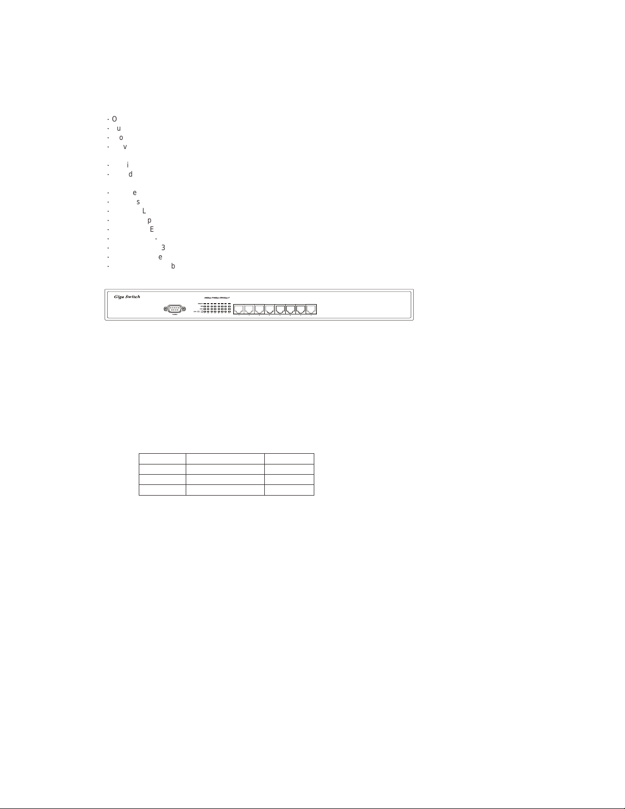
2.3 The Front Panel
GigabitEthernet Switch (19 inches case)
2.3.1 1000BASE-T
The switchis primarilyused for network backbone connections.
For the1000BASE-T TP port, it provides an Auto-Negotiationfunctionthat s enses for the attached device's maximum
operating speed and automatically sets the Switch to operate at that speed. Users only need to connect a network cable into
any TP port, and the Auto-Negotiation function will do the rest.
2.3.2 Cabling
1000Mbps- To transmitat1000Mbps requires Category5 TP cabling that must use all Four (4) pairs twisted-pair wire for
100Mbps- To transmitat 100Mbps requiresCategory 5 TP cabling.
10Mbps- When transmitting at 10Mbps Category3, 4 or 5 TP cabling with RJ-45 socketscan be used.
Note: Category 5 TP cable recommended whenever installing new cabling.
Totransmit at 1000Mbps requires Category 5 TP cable using Four (4) pairsTwisted-Pairwire.
RJ-45 connector.
PortType CableType Connector
1000BASE-T Cat.5 TP RJ-45
100BASE-TX Cat.5TP RJ-45
10BASE-T Category 3, 4 or 5 TP RJ-45
4
Page 5

2.3.3 Status LEDs
The Switch comes with a complete range of LEDs. The table below lists each LEDs name, color and a brief description of its
function.
Name Color Function
Green Power on, normal operationPower
Off Power off
Link/Act
Green Link On
Blink Activity
Off Link Off
Green 1000M Speed1000M
Off Not 1000M Speed
Green 100M Speed10M/100M
Off 10Mspeed
Full Green Full-duplexm ode
Collision Blinking Collision
Half Off Half-duplexmode
2.4 The Rear Panel
GigabitEthernet Switch (19 inches case)
2.4.1 Power Socket
The PowerSocketis designed to be used with the power cord included in the productpackage.
ƍ
Attach the female end of the power cord to the male power connector on the back panel.
ƍ
Attach the m ale end of the power cord to a grounded power outlet.
2.4.2 Network Ports
The Switchprovides Eight (8) 10BASE-T/100BASE-TX/1000BASE-T (RJ-45 connector) ports.
2.4.3 ConsolePort
The consoleportinterface conforms to the RS-232 electrical specification.This interface supports asynchronous data of Eight
(8) databits,One(1) stop bit, and no parity bit. The unit only operates at38400bpsrates with RS-232 cable in system
configure.
5
Page 6
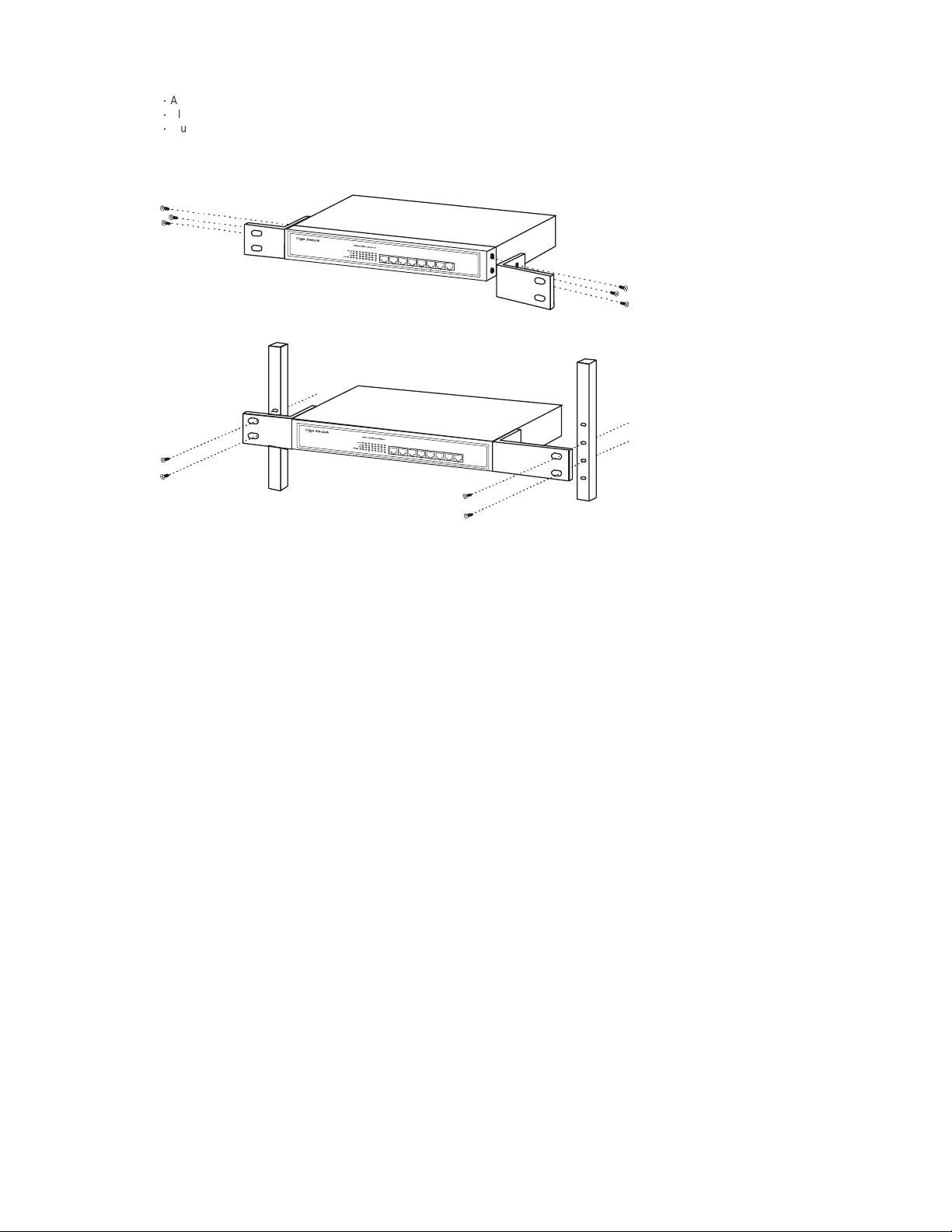
3 INST A LLATION
Tolocate the switch on a rackmount: (19 inches case only)
ƍ
Attach the Four (4) rubber feet included in the product package to the bottom of the Switch, one in each corner.
ƍ
Place the Switch on a rackmount.
ƍ
Plug in all network connections and the power cord
3.1 Rackmount placement
Attach One (1) rackmounting bracket on each side of the Switch front panel and secure each bracket with the provided
screws.
Use the otherprovidedscrews to secure each Switch to the rack.
6
Page 7

4 HELPFUL SUGGESTIONS
4.1 Prior to Installation
Beforeinstalling the Switch and connectingnetwork devices, it is importantto plan the network's layout. Things you should
considerinclude:
ƍ
DedicatedBandwidth: File servers and other high-traffic hardware improve their performance if they have their own
dedicated 10Mbps, 100Mbps,or1000Mbpsbandwidth.
ƍ
Full-Duplex: Determine which devicessupport Full-Duplex connections.
ƍ
Fast Ethernet& Gigabit Ethernet: Make sure rules for cable lengths and categories are followed. 100BASE-TX and
1000BASE-Thave the same rules for cable and distance.
ƍ
Auto-Negotiation: Devices withdifferent speeds may be easily swapped when the other end of the cable is fixed to a port
with Auto-Negotiation.
4.2 Half- and Full-Duplex
The Switchsupports both Half- and Full-Duplexmodesfor10BASE-T and 100BASE-TX. But the 1000BASE-Tonlysupports
Full-Duplex mode.
ƍ
In Half-Duplex mode: Datacannotbe transmitted and received at the same time.Attached devicesmust finish transmitting
data before they can receive data.
ƍ
In Full-Duplex mode: Data can be transmittedandreceived at th e s ame time.
However:
ƍ
Full-Duplex transmission is only possible between two devices with a dedicated link (e.g., Switch-Switch, Switch-PC)
ƍ
Bothdevicesmust have Full-Duplex capability
ƍ
Bothdevicesmust b e set to Full-Duplex(e.g.Auto-Negotiation – Auto-Negotiation, Non-Auto-Negotiation to
Non-Auto-Negotiation)
The 100BASE-TX/10BASE-Tor1000BASE-T/100BASE-TX/10BASE-Tports on the S witch detect and set the line's operating
modebyusing theirAuto-Negotiation function.
4.3 Auto-Negotiation
Every1000/100/10Mbps speedportontheseSwitches has a built-in "Auto-Negotiation" function.This technology
automatically sets the best possible bandwidth as soon as a connection is established with another network device (usually at
Power“On” or Reset).This is capabilityis achievedvia the Switch’sAuto-Negotiation function that automatically detects the
modes and speeds the second (attached) device is capable of.
Evaluating Auto-Negotiation Capability:
if attached device is: the Switch will automatically set its TP ports to operate at:
1000Mbps
with Auto-Negotiation
100Mbps
noAuto-Negotiation
100Mbps
with Auto-Negotiation
10Mbps
noAuto-Negotiation
10Mbps
with Auto-Negotiation
Note: If the attached device is set to a fixed mode (ex: Forced Full-Duplex) it will not operate as an Auto-Negotiation device.
2000Mbps (1000BASE-T, Full-Duplex)
Note:Almost all 1000Mbps devicesonly operatein Full-Duplexm ode.
100Mbps(100BASE-TX,Half-Duplex)
200Mbps(100BASE-TX, Full-Duplex)
10Mbps(10BASE-T,Half-Duplex)
20Mbps(10BASE-T,Full-Duplex)
4.4 MAC Address Table
EveryEthernet data packet includesboth s ource and destination addresses. This Six (6) bytes IDis calledtheMAC (Media
AccessControl) Address. It supports16 K MAC address.
The model can automatically learn and store MAC addresses. However, the MAC address table is volatile: it disappears when
the Switch is powered “Off” or reset.
Note:When the network needs reconfiguration, we recommend to restart the Switch first. After all nodes have been moved,
Remove the power cord and re-attach it to rebuild the internal MAC address table.
7
Page 8

5 SAMPLE APPLICATION
The application for theseSwitches is as a "big pipe" backbone interconnecting file servers with bandwidth-hungry workgroups,
departments, and offices.
2410/100portswith 2 Gigabit portsswitch
24-Port+ 2 GigaPort Switch
200Mbps
Full-Duplex
100m max.
Workstationswith10/100
Fast Ethe rne t Ad ap ters
Prin te r
Pri n t er Se r v er
2000Mbps
Full-D uplex
100m max.
Workstationswith10/100
Fast Ethernet Adapters
ServerwithGigabit Ethernet Adapter
8
Page 9

6 SMART FUNCTION CONFIGURATION
6.1 HyperTerminal
The Switch has a smart function that you can use to manage your local area network (LAN) more effectively. You can also use
the default setting to operate the Switch as a dumb switch.
If you want to use smart function, install the Switch as below:
ƍ
Usethe“RS-232”connectortoconnect theSwitchto acomputer. ConnectOne(1) cable end to the Switch, andconnectthe
otherendto the computer’s“COM1”or“COM2”port.
Note: Ifyour Windowsprogram doesn’t have a hyper terminal, you have to install it first.
ƍ
Power“ON”theSwitch
ƍ
Executethe “HyperTerminal” program:
Start Menu ! Application Program ! Communication ! Hyper Terminal
ƍ
Setup the connection content of Hyper Terminal:
ƍ
In connection tag, select which “COM” port is used to connect PC and the Switch.
ƍ
Thenpressthe “SETUP” button, set “Bitspersecond”to38400, “Data bits” to 8,“Parity”toNone,“Stopbits”to1,“Flow
control” to None.
9
Page 10

1
6.2 System Initiating
After you have set up the “HyperTerminal” program, you can power on the switch.
You will see the initializing processappears on the screen.
Hjhbcju!Fuifsofu!Tnbsu!Txjudi!
Qpxfs.vq!Tztufn!Tfmg.ejbhoptujd!Qspdftt!
W2/11!13.36.3113!)d*!Dpqzsjhiu!3113/!
!
Dpotpmf!J0P!uftu!///!
!!"#$%&'()*+,-./0123456789:;<=>?@ABCDEFGHIJKLMNOPQRSTUVWXYZ[\]^_`a!
!!bcdefghijklmnopqrstuvwxyz{|}~!
!
SBN!uftu!///////////QBTT!
FFQSPN!uftu!////////QBTT!
FF!joufsgbdf!uftu!Qbtt"!
NJJ!uftu!Tvddftt!
NBJOCPBSE!DPN!!!SBNCJTU!UFTU!///////QBTT"!
NBJOCPBSE!BMF!!!SBNCJTU!UFTU!///////QBTT"!
NBJOCPBSE!TDN!!!SBNCJTU!UFTU!///////QBTT"!
NBJOCPBSE!HQD2!!SBNCJTU!UFTU!///////QBTT"!
NBJOCPBSE!HQD3!!SBNCJTU!UFTU!///////QBTT"!
NBJOCPBSE!HQD4!!SBNCJTU!UFTU!///////QBTT"!
NBJOCPBSE!HQD5!!SBNCJTU!UFTU!///////QBTT"!
NBJOCPBSE!HQD6!!SBNCJTU!UFTU!///////QBTT"!
NBJOCPBSE!HQD7!!SBNCJTU!UFTU!///////QBTT"!
NBJOCPBSE!HQD8!!SBNCJTU!UFTU!///////QBTT"!
NBJOCPBSE!HQD9!!SBNCJTU!UFTU!///////QBTT"!
Qsftt!=Foufs?!up!foufs!uif!vtfs!joufsgbdf!qsphsbn/!
Here we can see messages shownin this power-onscreen. As describedin the screen, this is a Self-Diagnosticprocess
running duringpower-on stage.Regardless of the t est result is successful or not, you are always requestedtopress<Enter>
to enternextstage.
After you press <Enter> to enter the user interface program, you will see the screen shown as follow:
!
!
!
!
!!!!!!!!!!!!!!!!!!!!!!!!!!!!!!!!!!Tnbsu!Txjudi!
!
!!!!!!!!!!!!!!!!!!!!!!!!!!!!!!!!!Vtfs!Joufsgbdf!
!
!!!!!!!!!!!!!!!!!!!!!!!!!!!!!w2/11!)d*!Dpqzsjhiu!3113!
!
!
!
!
!
!
!!!!!!!!!!!!!!!!!!!!!!!!Qbttxpse!;!
!
!
!
!
!
!
Log-in is requiredtoaccess the command console. Apassword is used to provide the basic securitycontrol.The factory
defaultpassword is “admin”.The user can change passwordoncein theSystemmenu. If the password is forgotten, user must
returnthisdevice for SW maintenance. In this log-in screen, input the correct password and press enter will lead user to main
menu. Without valid password, user cannot monitor the system status or set special functions from this interface. We
recommend users take special care of the password.
0
Page 11

7 USE FUNCTION MENU
7.1 Main menu
The main menu is the top level of all menu-driven screens. All functions are selected from this screen.
The main menu function selections are listed below:
1. SystemConfiguration
2. Port Configuration
3. PortTrunkingConfiguration
4. Port Mirroring Configuration
5. VLAN Configuration
6. PriorityConfiguration
7. Port Statistics
8. Restart
9. Exit
!
!
!!!!!!!!!!!!!!!!!!!!!!!!!!!!!!!Nbjo!Nfov!
!!!!!!!!!!!!!!!!!!!!!!!!!!!!!!!>>>>>>>>>!
!!!!!!!!!!!!!!!!!!!!!!!!!!!Tztufn!Dpogjhvsbujpo!///!
!
!!!!!!!!!!!!!!!!!!!!!!!!!!!Qpsu!Dpogjhvsbujpo!///!
!
!!!!!!!!!!!!!!!!!!!!!!!!!!!Qpsu!Usvoljoh!Dpogjhvsbujpo!///!
!
!!!!!!!!!!!!!!!!!!!!!!!!!!!Qpsu!Njsspsjoh!Dpogjhvsbujpo!///!
!
!!!!!!!!!!!!!!!!!!!!!!!!!!!WMBO!Dpogjhvsbujpo!///!
!
!!!!!!!!!!!!!!!!!!!!!!!!!!!Qsjpsjuz!Dpogjhvsbujpo!///!
!
!!!!!!!!!!!!!!!!!!!!!!!!!!!Qpsu!Tubujtujd!///!
!
!!!!!!!!!!!!!!!!!!!!!!!!!!!Sftubsu!///!
!
!!!!!!!!!!!!!!!!!!!!!!!!!!!Fyju!
!
!!!!!!!!!!!!!!!!!!!!!!!!!!!!Dpogjhvsf!uif!qbttxpse/!
!!!!!!!!!!!!!!!!!!Vtf!bsspx!lfzt!up!npwf/!=Foufs?!up!dpogjsn/!
You can press the number key (on the right hand side of the keyboard) 8 for moving up the menu bar and 2 for moving down.
When the menu bar stops on the right item that you want to execute, press “Enter” to go into the sub-menu.
Note: Beforeusing number keyformovingup or down,pleasemakesure the“NumLock”LED should not be lit.
There are 4 types of arrow indicator messages which are listed below:
Item Explanation
[8]:Up Press the number key 8 to move UP your menu bar.
[2]:Down Press the number key 2 to move DOWN your menu bar.
[6]:Right Press the number key 6 to move RIGHT your menu bar.
[4]:Left Press the number key 4 to move LEFT your menu bar.
[Enter]:Execute Press Enter to EXECUTE the sub-menu.
[Space]:Option PressSpacebar to change the currentsettingtonext option.
[ESC]=Exit Press ESC to EXIT the sub-menu.
7.2 System Configuration
If we want to enable aging time of the system, select” System configuration” sub-menu and press “Enter” to execute. We’ll see
thefollowingmenuon the screen.
!
!!!!!!!!!!!!!!!!!!!!!!!!Tnbsu!Txjudi!;!Tztufn!Dpogjhvsbujpo!
!!!!!!!!!!!!!!!!!!!!!!!!>>>>>>>>>>>>>!
!
!
!
!
!
!
!!!!!!!!!!!!!!!!!!!!!!!Qbttxpse!!!!!!!!!!;benjo!
!
!!!!!!!!!!!!!!!!!!!!!!!Bhjoh!ujnf!!!!!!!!;411!!!!!!!!!!!)tfdpoet*!
!
!!!!!!!!!!!!!!!!!!!!!!!Mphpvu!ujnf!!!!!!!;1!!!!!!!!!!!!!)njovuft*!
!
!!!!!!!!!!!!!!!!!!!!!!!Bvup!sfgsfti!ujnf!;23!!!!!!!!!!!!)tfdpoet*!
!
!
!
!
!!!!!!!!!!!!!!!!!!!!!!!!!!!!!!!!!!=!Sfuvso!?!
!!!!!!!!!!!!!!!!!!Qbttxpse!pg!uif!benjojtusbups/!!!!!!!!!!!!!!!!!!}!SFBE0XSJUF!
!!!!!!!!!!!!!!!Vtf!bsspx!lfzt!up!npwf/!=Foufs?!up!nblf!dibohft/!
11
Page 12

1
In the “SystemConfiguration” menu,you can setup the followingsettings.
Item default explanation
Password admin
The login password.
(Astring)
Aging time 300
(Integer, in seconds)
Logouttime 0
(Integer, in minutes)
Forwarding table aging period
AgingTimevalue is between 0~65000.
Set the automatic logout time. The console will be
automatically logged out if idle time period over this
setting.
LogoutTime value is between 0~255.
Auto refresh time 12
(Integer, in seconds)
Many consolescreens contain data that can be
updatedconstantly. This parametercontrols the time
betweeneach screen update.
AutoRefresh Time value is between 0~255.
7.3 Port Configuration
When you go into the “Port Configuration” sub-menu,the currentstatewill be scannedfor all 8 ports of the Switch and shown
on the screen as follow:
!
!!!!!!!!!!!!!!!!!Tnbsu!Txjudi;!Qpsu!Dpogjhvsbujpo!
!!!!!!!!!!!!!!!!!>>>>>>>>>>>>!
!
!Qpsu!!Mjol!!!!!Benjo!!!!!Uzqf!!!!!!!!Dvssfou!!!!!!Gmpx!!!!!!!!!Gmpx!Dpouspm!
!!!!!!!Tubuvt!!!Tubuvt!!!!Dpogjh!!!!!!Uzqf!!!!!!!!!Dpouspm!!!!!!Tubuvt!
!......................................................................!
!12/!!!Pgg!!!!!!Fobcmfe!!!Bvup.Ofhp!!!21IEY!!!!!!!!Pgg!!!!!!!!!!Pgg!
!13/!!!Pgg!!!!!!Fobcmfe!!!Bvup.Ofhp!!!21IEY!!!!!!!!Pgg!!!!!!!!!!Pgg!
!14/!!!Pgg!!!!!!Fobcmfe!!!Bvup.Ofhp!!!21IEY!!!!!!!!Pgg!!!!!!!!!!Pgg!
!15/!!!Pgg!!!!!!Fobcmfe!!!Bvup.Ofhp!!!21IEY!!!!!!!!Pgg!!!!!!!!!!Pgg!
!16/!!!Pgg!!!!!!Fobcmfe!!!Bvup.Ofhp!!!21IEY!!!!!!!!Pgg!!!!!!!!!!Pgg!
!17/!!!Pgg!!!!!!Fobcmfe!!!Bvup.Ofhp!!!21IEY!!!!!!!!Pgg!!!!!!!!!!Pgg!
!18/!!!Pgg!!!!!!Fobcmfe!!!Bvup.Ofhp!!!21IEY!!!!!!!!Pgg!!!!!!!!!!Pgg!
!19/!!!Pgg!!!!!!Fobcmfe!!!Bvup.Ofhp!!!21IEY!!!!!!!!Pgg!!!!!!!!!!Pgg!
!
!
!
!
!
!!!!!!!!!!!!!!!!!!!!!!!!!!!!!!!!!!=!Sfuvso!?!
!!!!!!!!!!!!!!!!!!!!Dpogjhvsf!uif!qpsu!tubuvt/!!!!!!!!!!!!!!!!!!!!}!SFBE0TFMFDU!
!!!!!!!!!!!!!!!!!!Vtf!bsspx!lfzt!up!npwf/!=Tqbdf?!up!nblf!dibohf/!
The Port Configuration Screen provides configurable setting and current status for each port. For each Ethernet port, following
settingsare available:
Item Type default selections Explanation
Port R N/A N/A You can select from 1 to 8 port for setting up.
Link Status R N/A N/A Port Link status. If the port links, it shows “On”
Admin
Status
TypeConfig R/W Auto-Nego
CurrentType R N/A N/A Current Statusof thelink speedandduplex
Flow Control R/W Off
R/W Enabled Enabled
Disabled
Auto-Nego Auto-Negotiation
10HDX 10BASE-T, Half-Duplexmode
10FDX 10BASE-T, Full-Duplexmode
100TX-HDX 100BASE-TX, Half-Duplexmode
100TX-FDX 100BASE-TX,Full-Duplex mode
1GB-FDX 1000BASE-T, Full-Duplex mode
Off No Flow-Control
BothWay Accept Pause frame and issue Pause frame.
SendOnly OnlyissuePause frame and ignore received
Rcv/BothWay Accept Pause frame and issue Pause frame,
Flow Control
Status
R N/A N/A CurrentFlowc ontrol result with link partner.
else “Off”.
Port transmission enable/disable.
Preferred Port speed and duplex setting.
with link partner.
Flow control mode selection.
frame.
same as Bothway.
Userscan onlymonitorfollowing items: Link Status/ Current Type / Flow Control Status.
Users can set up the following items: Admin Status / Type Config / Flow Control
2
Page 13

1
7.4 Port Trunking Configuration
PortTrunking Configuration menu controls port trunking or theso called LinkAggregation function.Severalports in the Smart
Switchcanbe bundled togethertoform a high-speed trunk. The available choicesarelisted in th e screen once y ou press
<Add> selection.
!
!!!!!!!!!!!!!!!!!!!!!!!!Tnbsu!Txjudi;!Qpsu!Usvoljoh!Dpogjhvsbujpo!
!!!!!!!!!!!!!!!!!!!!!!!!>>>>>>>>>>>>!
!
!!!Mjtu!Dvssfou!Mjol!Bhhsfhbuft!
!!!!!!!!!!!Qpsu!Dpvou!!!!Qpsu!Ovncfs!
!
!
!
!
!
!
!
!
!
!
!
!
!
!
!!!!!!!!!!!!!!!!!!!!!!!!!!!!!=!Sfuvso!?!!!!!!!!!!!!!!!!!=Bee?!
!!!!!!!!!!!!!!!!!!!!!!!!!!!!Bee!usvoljoh!qpsu!hspvq!
!!!!!!!!!!!!!!!!!!Vtf!bsspx!lfzt!up!npwf/!=Foufs?!up!dpogjsn/!
For factory default setting, the trunking group list is empty. Toset up a new trunk, select the <Add> function.T he f ollowing
selections list will be shown on screen.
!
!
!
!
!!!!!!!!!!!!!!!!!!!Qpsu!Usvoljoh!Dpogjhvsbujpo;!Bee!Usvoljoh!Qpsu!
!!!!!!!!!!!!!!!!!!!>>>>>>>>>>>>>>>>>>>>>>>>>>>!
!
!!!!!!!!!!!!!!!!!!!3.qpsu;!
!!!!!!!!!!!!!!!!!!!!!!!!==!2!up!3!??!!!==!4!up!5!??!
!!!!!!!!!!!!!!!!!!!!!!!!==!6!up!7!??!!!==!8!up!9!??!
!!!!!!!!!!!!!!!!!!!4.qpsu;!
!!!!!!!!!!!!!!!!!!!!!!!!==!2!up!4!??!!!==!3!up!5!??!
!!!!!!!!!!!!!!!!!!!!!!!!==!6!up!8!??!!!==!7!up!9!??!
!!!!!!!!!!!!!!!!!!!5.qpsu;!
!!!!!!!!!!!!!!!!!!!!!!!!==!2!up!5!??!!!==!6!up!9!??!
!
!
!
!!!!!!!!!!!!!!+++!Opuf;!Usvoljoh!ibt!up!cf!xjuijo!uif!tbnf!WMBO/!+++!
!
!!!!!!!!!!!!!!!!!!!!!!!!!!!!!!!!!!!!!=!Sfuvso!?!
!!!!!!!!!!!!!!!!!!!!!!!!!!!!!Bee!qpsu!usvol!pqujpo/!
!!!!!!!!!!!!!!!!!!Vtf!bsspx!lfzt!up!npwf/!=Foufs?!up!dpogjsn/!
Eachitemrepresents a set of ports that can be trunked together. Pressing <Enter>on an item selectstheset as a new trunk.
Note that selecting a set of port may cause other sets to be excluded in further selections. More sets can be selected until all
portsaredefined.
3
Page 14

1
The following Figure. shows a sample of Trunking Configuration screen after some trunking ports are defined.
!
!
!!!!!!!!!!!!!!!!!!!!!!!!Tnbsu!Txjudi;!Qpsu!Usvoljoh!Dpogjhvsbujpo!
!!!!!!!!!!!!!!!!!!!!!!!!>>>>>>>>>>>>!
!
!!!Mjtu!Dvssfou!Mjol!Bhhsfhbuft!
!!!!!!!!!!!Qpsu!Dpvou!!!!Qpsu!Ovncfs!
!!!Usvol2!!3!!!!!!!!!!!!!qpsu!2!up!3!
!!!Usvol3!!3!!!!!!!!!!!!!qpsu!4!up!5!
!!!Usvol4!!5!!!!!!!!!!!!!qpsu!6!up!9!
!
!
!
!
!
!
!
!
!
!
!
!!!!!!!!!!!!!!!!!!!!!!!!!!!!!=!Sfuvso!?!
!!!!!!!!!!!!!!!!!!!!!!!!!!!!!Efmfuf!usvol2!tfuujoh/!
!!!!!!!!!!!!!!!!!!Vtf!bsspx!lfzt!up!npwf/!=Foufs?!up!dpogjsn/!
The trunkedgroupcanalsobeselected for deletion. Todelete a trunk, simply use arrow keys & move and press Enter to
select.The f ollowing question will appearatthestatus line:
Are you sure you want to perform this operation? (y/n)
PressYwilldeleteselected trunk group.
Note: You can’t assign 2 of differentswitch’sports to the same VLAN group.
Note: Members in trunk should be in the same VLAN
7.5 Port Mirroring Configuration
PortMirroringmeans setting up a m onitored port so that data flowing through thatportis copied to the 8
tomonitorotherportsis calledthe Monitoringport. It is fixed at 8
th
port. The ports being watched are called the Mirrored Port.
The Smart Switch is able to monitor one port at one time. The transmitting and receiving direction can be monitored
exclusively.Besure to activatethisfunction before setting port selection and direction.
!
!!!!!!!!!!!!!!!!!!!!!!!!Tnbsu!Txjudi!;!Njssps!Qpsu!Dpogjhvsbujpo!
!!!!!!!!!!!!!!!!!!!!!!!!>>>>>>>>>>>>>!
!
!
!
!
!
!!!!!!!!!!!!!!!!!!!Npojupsfe!Qpsu;!
!
!
!!!!!!!!!!!!!!!!!!!!!!!!!!!!!Qpsu!Uzqf!!!!!!!Bdujwf!
!!!!!!!!!!!!!!!!!!!!!!!!!!!!!.........................!
!!!!!!!!!!!!!!!!!!!!!!!!!!!!!2!!!!Sy!Qbdlfut!Ejtbcmfe!
!
!
!
!!!!!!!!!+++!Opuf;!!+++!
!!!!!!!!!Uif!tqffe!pg!npojupsfe!qpsu!nvtu!ibwf!uif!tqffe!bt!9(ui!qpsu/!
!
!!!!!!!!!!!!!!!!!!!!!!!!!!!!!!!!!!!!!=!Sfuvso!?!
!
!!!!!!!!!!!!!!!Vtf!bsspx!lfzt!up!npwf/!=Foufs?!up!nblf!dibohft/!
The following items are available for Port Mirrowing configuration.
item selections explanation
Port 1-7 Port to be Monitored.
Type Rx Packets
Transmitor Receive direction to be monitored.
Tx Packets
Active Disabled
Disable/Enable Monitor function of 8th port.
Enabled
For using Mirror function, some limitations should be noted here.
ƍ
The monitored and monitoring port should be running in the same speed.
ƍ
The transmitting or receiving rate of monitored port should not exceed the wire speed of the 8thport (monitoring port).
th
port.T he port used
4
Page 15

1
7.6 VLAN Configuration
The VLAN Configuration sets up the VLAN configuration of this switch.T he Switch supports 32 VLANs in f our pages. Each
VLANcanhave an ID with range 1-4094, 0 and 4095 arestandard reservation.Member set in the same VLAN can be
untaggedor tagged. Incoming untagged packet will be assigned Port VID of that port.Following is the configurationscreen for
VLAN function.
!
!!!!!!!!!!!!!!!!!!!!!!!!Tnbsu!Txjudi!;!WMBO!Ubcmf!)2!up!9*!
!!!!!!!!!!!!!!!!!!!!!!!!>>>>>>>>>>>>>!
!
!!!!!!!!!!!!!!!!!!!Qpsu!!!!Nfncfs!Tfu!!!!!!!!Voubh!Tfu!
!!!!!!!!!!!!!!WMBO!!!!!!!!!23456789!!!!!!!!!!23456789!
!
!!!!!!!!!!!!!!2!!!!!!!!!!!!QQQQQQQQ!!!!!!!!!!VVVVVVVV!!!!!!!!!!!T!;!Tubujd!
!!!!!!!!!!!!!!!!!!!!!!!!!!!!!!!!!!!!!!!!!!!!!!!!!!!!!!!!!!!!!!!!Q!;!QWJE!
!!!!!!!!!!!!!!!!!!!!!!!!!!!!!!!!!!!!!!!!!!!!!!!!!!!!!!!!!!!!!!!!V!;!Voubh!
!
!
!
!
!
!
!
!
!
!
!!!!!!!!!!!!!!!!!!=!Sfuvso!?!!!!!!=Bee?!!!=Qsfwjpvt!Qbhf?!=Ofyu!Qbhf?!
!!!!!!!!!!!!!!!!!!!!!!!!!!!!!Npejgz!uif!WMBO!hspvq/!
!!!!!!!!!!!!!!!!!!Vtf!bsspx!lfzt!up!npwf/!=Foufs?!up!dpogjsn/!
Each VLAN has a VLAN ID and a list of members. For each VLAN, a letter is used for specific port to represent the relation of
that port to the VLAN.
Initially all ports are PVID 1. To add a new VLAN, press the <Add> Command.The f ollowing screen appears:
!
!!!!!!!!!!!!!!!!!!!!!!!!Tnbsu!Txjudi!;!BEE!WMBO!
!!!!!!!!!!!!!!!!!!!!!!!!>>>>>>>>>>>>>!
!
!!!!!!!!!!!!!!!!!!!Qpsu!!!!Nfncfs!Tfu!!!!!!!!Voubh!Tfu!
!!!!!!!!!!!!!!WMBO!!!!!!!!!23456789!!!!!!!!!!23456789!
!
!!!!!!!!!!!!!!1!!!!!!!!!!!!!!!!!!!!!!!!!!!!!!!!!!!!!!!!!!!!!!!!!T!;!Tubujd!
!!!!!!!!!!!!!!!!!!!!!!!!!!!!!!!!!!!!!!!!!!!!!!!!!!!!!!!!!!!!!!!!Q!;!QWJE!
!!!!!!!!!!!!!!!!!!!!!!!!!!!!!!!!!!!!!!!!!!!!!!!!!!!!!!!!!!!!!!!!V!;!Voubh!
!
!
!
!
!
!
!
!
!
!
!!!!!!!!!!!!!!!!!!=Pl?!!!!!!!!!!!!!!!!!!!!!!!!!!!!!!!!!!=Dbodfm?!
!
!!!!!!!!!!!!!!!Vtf!bsspx!lfzt!up!npwf/!=Foufs?!up!nblf!dibohft/!
Toadd a new VLAN,input thenew VLAN ID, edit the member set and untag set of this VLAN. Press <OK> to completethis
setting.
When you want to modify existed VLAN configuration, just press <enter> when cursor is on that VLAN. Display will enter
Modify VLAN. Here user can use arrow key to move to target position thatneedstobe modified. VLAN can only be deleted at
this moment. A confirmation message appears on status bar. Press <Y/N> to complete process.
Move to <Config> and press <enter> activates the new VLAN setting and stays in this screen. Move to <Return> and press
<enter> completes modification and returns to the VLANConfiguration screen.
5
Page 16

1
7.7 PriorityConfiguration
The PriorityConfigurationsets the IEEE802.1p priority function of the system.
The SmartSwitchhas 4 priority queuesper port.Each framecanbe sent via high or low priority queuedependingonthe
prioritysetting and the tag value of it.
!
!!!!!!!!!!!!!!!!!!!!!!!!Tnbsu!Txjudi!;!Qpsu!Qsjpsjuz!Dpogjhvsbujpo!
!!!!!!!!!!!!!!!!!!!!!!!!>>>>>>>>>>>>>!
!
!
!
!!!!!!!!!Efgbvmu!ubht;!!!!!!!!!!!!!!!!!Qsjpsjuz!nbqqjoh!gps!fbdi!ubh;!
!
!
!!!!!!!!!Qpsu!2!3!4!5!6!7!8!9!!!!!!!!!!Ubh!!!1!2!3!4!5!6!7!8!
!
!!!!!!!!!Ubh!!1!1!1!1!1!1!1!1!!!!!!!!!!rvfvf!2!1!1!2!3!3!4!4!
!
!
!
!
!
!
!!!!!!!!!+++!Opuf;!Gmpx!dpouspm!ibt!up!cf!fobcmfe!cfgpsf!tfuujoh!qsjpsjuz/!+++!
!
!!!!!!!!!!!!!!!!!!!!!!!!!!!!!!!!!!=!Sfuvso!?!
!
!!!!!!!!!!!!!!!!!!Vtf!bsspx!lfzt!up!npwf/!=Tqbdf?!up!nblf!dibohf/!
Usercaninputanynumber between0~7atl eft-side “Tag” fieldt o assign tag value to eachport.These defaulttagssettings are
only for thosepackets without tag.After these packets are received, these default tags are appended into these packets. For
originallytagged frames, they haveno effect.
Atrightleftpartof this screen, the mapping oftagvalue to actual priorityaredefined here by enter 0~3 number to“queue”field.
The queue3 has thehighestpriority. The prioritydistribution of 0~3 are 1:7:15:31. Packet with tag 0 is always put into queue
1accordingtothestandard.
7.8 Port Statistics
Usercandisplayindividual statistical counter of selected port.The update rate can be defined in System configuration page.
They aregood for administrator to monitor each port’susage condition.Also,itis helpfultotroubleshooting network problems.
!
!
!!!!!!!!!!!!!!!!!Tnbsu!Txjudi;!Qpsu!Tubujtujd!
!!!!!!!!!!!!!!!!!>>>>>>>>>>>>!
!
Joufsgbdft!
!!!Jo!Pdufut!!!!!!!!!!!!!;!1!!!!!!!!!!!!!!!Pvu!Pdufut!!!!!!!!!!!!;!1!
!!!Jo!Vojdbtu!Qlut!!!!!!!;!1!!!!!!!!!!!!!!!Pvu!Vojdbtu!Qlut!!!!!!;!1!
!!!Jo!Opo.Vojdbtu!Qlut!!!;!1!!!!!!!!!!!!!!!Pvu!Opo.Vojdbtu!Qlut!!;!1!
!!!Jo!Ejtdbset!!!!!!!!!!!;!1!!!!!!!!!!!!!!!Pvu!Ejtdbset!!!!!!!!!!;!1!
!!!Jo!Fsspst!!!!!!!!!!!!!;!1!!!!!!!!!!!!!!!Pvu!Fsspst!!!!!!!!!!!!;!1!
!!!Bmjhonfou!Fsspst!!!!!!;!1!!!!!!!!!!!!!!!DSD!Fsspst!!!!!!!!!!!!;!1!
!
Fuifsofu!
!!!Tjohmf!Dpmmjtjpot!!!!!;!1!!!!!!!!!!!!!!!Nvmujqmf!Dpmmjtjpot!!!;!1!
!!!Efgfssfe!Usbotnjttjpot!;1!!!!!!!!!!!!!!!Mbuf!Dpmmjtjpot!!!!!!!;!1!
!!!Fydftt!Dpmmjtjpot!!!!!;!1!!!!!!!!!!!!!!!Dbssjfs!Tfotf!Fsspst!!;!1!
!!!Espq!Fwfout!!!!!!!!!!!;!1!!!!!!!!!!!!!!!Gsbhnfout!!!!!!!!!!!!!;!1!
!!!Pdufut!!!!!!!!!!!!!!!!;!1!!!!!!!!!!!!!!!Kbccfst!!!!!!!!!!!!!!!;!1!
!
!!!!Qpsu!Ovncfs;!!2!!!!!=Sfgsfti?!!!!!!!!!!!=Qsfwjpvt!Qpsu?!!!!!=Ofyu!Qpsu?!
!!!!=!Sfuvso!?!!!!!!!!!!=Sftfu?!!!!!!!!!!!!!=Sftfu!Bmm?!
!!!!!!!!!!Ejtqmbz!qpsu!tubujtujdt!efgjofe!jo!tvdi!qbhf/!!!!!!!!!!!}!SFBE0XSJUF!
!!!!!!!!!!!!!!!Vtf!bsspx!lfzt!up!npwf/!=Foufs?!up!nblf!dibohft/!
6
Page 17

1
7.9 Restart
The Reset menu provides 2 functions.
Factory Default Clear the configuration data and load factory default setting into switch. The
switch will then be restarted.
Restart Performs a SW reset of system.
!
!
!!!!!!!!!!!!!!!!!!!!!!!!Tnbsu!Txjudi!;!Tztufn!Sftubsu!
!!!!!!!!!!!!!!!!!!!!!!!!>>>>>>>>>>>>>!
!
!
!
!
!
!
!!!!!!!!!!!!!!!!!!!!!!!!!!!!!=Gbdupsz!efgbvmu?!
!
!!!!!!!!!!!!!!!!!!!!!!!!!!!!!=Sftubsu?!
!
!
!
!
!
!
!
!
!!!!!!!!!!!!!!!!!!!!!!!!!!!!!!!!!!=!Sfuvso!?!
!!!!!!!!!!!!!!!!!!!!!!!Sftfu!up!gbdupsz!efgbvmu!tfuujoh/!
!!!!!!!!!!!!!!!!!!Vtf!bsspx!lfzt!up!npwf/!=Foufs?!up!dpogjsn/!
7.10 Exit
Move cursor to “Exit” and press <enter> will jump to this screen. Follow instruction on screen can drive display to login page.
!
!
!
!
!
!
!
!
!
!
!!!!!!!!!!!!!!!Zpv!ibwf!fyjufe!gspn!uif!vtfs!joufsgbdf!qsphsbn/!
!
!
!
!
!
!
!!!!!!!!!!!!!Jg!zpv!xbou!up!sfuvso!up!uif!vtfs!joufsgbdf!qsphsbn-!
!!!!!!!!!!!!!!!!!!!!!!!!!!!qsftt!=Foufs?!sfqfbufemz/!
!
!
!
!
7
Page 18

1
8 PRODUCT SPECIFICA TIONS
Standards
Ports
MediaSupport
Bandwidth
Forwarding/Filtering
Rate
Latency
MACAddresses
Console port
Buffer Memory
DuplexModes
Crossover
Switch
LED Indicators
PowerSupply
Power Consumptionƍ30 W maximum
Environment
Dimensions
(19 inches case)
ƍ
IEEE802.3:10BASE-T
ƍ
IEEE802.3u:100BASE-TX
ƍ
IEEE802.3ab:1000BASE-T
ƍ
IEEE802.3x:Flow-Control support
ƍ
IEEE802.1D (Bridging)
ƍ
IEEE802.1P(Priority)
ƍ
IEEE802.1Q(Virtual LAN)
ƍ
Eight (8) 1000BASE-T/100BASE-TX/10BASE-TTP CopperPorts
ƍ
10BASE-T:Category 3, 4 or 5 TP
ƍ
1000BASE-TX/1000BASE-T: Category5 TP
ƍ
1000BASE-T2000/1000/200/100/20/10 Mbps
ƍ
1488000 packets/secondper port @ 1000Mbps maximum
ƍ
148800 packets/second per port @ 100Mbps maximum
ƍ
14880 packets/second per port @ 10Mbps maximum
ƍ
2.2µsec@1000Mbps minimum
ƍ
11 µsec @100Mbps minimum
ƍ
75 µsec @ 10Mbps minimum
ƍ
16K Self-Learning
ƍ
RS232 Cable
ƍ
1.5M bytesdatapackagememory
ƍ
Auto-Negotiation
ƍ
All ports have Auto-Crossover function
ƍ
One(1) for Power
ƍ
One(1) per port for display Link/ACT
ƍ
One(1) per port for display speed-1000Mbps(Green)
ƍ
One(1) per port for display 100Mbps(Green) or 10Mbps(Off)
ƍ
One(1) per port for display Full-duplexand Half –Duplex (collision)
ƍ
Full range Auto-Switching
ƍ
Inputvoltage: 100 ~ 240 +-10% VAC/ 50 ~ 60Hz
ƍ
Operating Temperature: 0° ~45°C(32° ~113°F)
ƍ
Storage Temperature: 0° ~70°C
ƍ
Humidity:10% ~ 90% Non-Condensing
ƍ
442 x 185 x 44mm
(17.40x7.28x1.73 inches)
8-PortGigabit Ethernet Smart SwitchModel
This equipment has been tested and found to comply with the limits for a Class Acomputing device pursuant to
Part 15 of FCC Rules, which are designed to provide reasonable protection against electromagnetic interference
in a commercial environment.
Changes or modifications to the equipment not expressly approved by the party responsible for compliance could
void the user's authority to operate the equipment.
This is a Class A product. In a domestic environment this product may cause radio interference in which case the
user may be required to take adequate measures.
FCC WARNING
CE MARK WARNING
8
 Loading...