

Page 1
Warning!
Safety Precautions
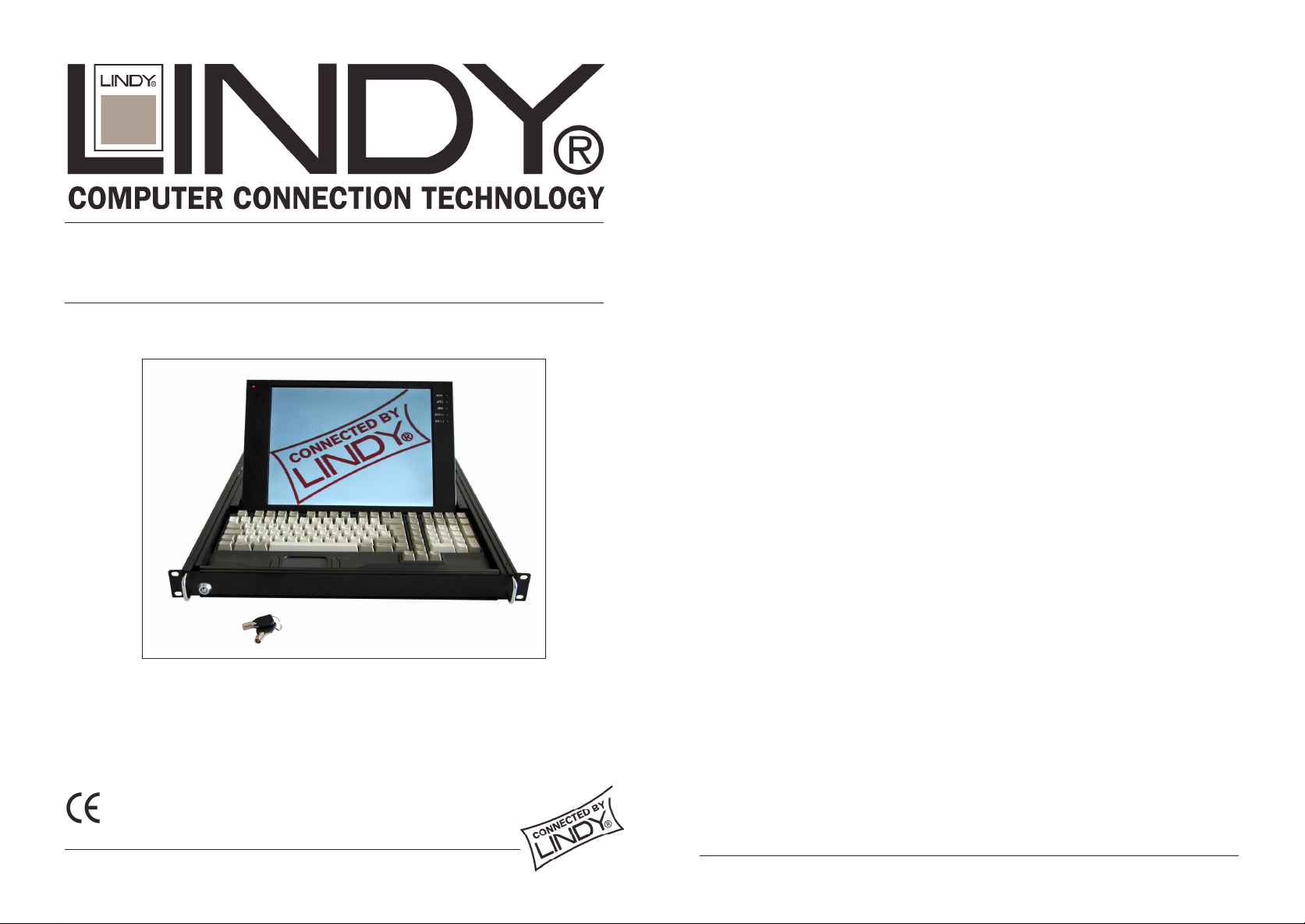
LINDY LCD Terminal
User Manual
LINDY Art.No. 21510 - 21515
• In order to avoid the risk of fire or electric shock DO NOT expose the
device to liquid ora high humidity environment.
• Operate the LCD only at temperatures between +5°C and +45°C.
•
There are no user serviceable parts. Qualif ied specialists must carry
out repairs only.
• The notes and instructions regarding this device must be observed.
• This device should always to be placed upon a solid horizontal
surface.
• Only clean with neutral cleaning agents and a damp cloth. Do not use
liquid cleaning agents or agents containing abrasives.
• To guarantee problem-free operation please ensure that there is
sufficient ventilation to prevent any d amage caused by overheating.
Never obstruct or block the ventilation slots o r other openings with
objects, and do not position the d evice in any location where there is
insufficient ventilation.
Features
• 14.1“ 1024 x 768 TFT LCD
• VGA, SVGA, and XGA video support.
• PS/2 touch pad.
• 105 keys mechanical switch keyboard
• Dimensions: Width 448mm x Height 44mm x Depth 5 90mm
www.LINDY.com
© LINDY ELECTRONICS LIMITED & LINDY-ELEKTRONIK GMBH - FIRST EDITION (AUG 2002)
© LINDY ELECTRONICS LIMITED & LINDY-ELEKTRONIK GMBH - FIRST EDITION (AUG 2002)
Page 2
User Manual KVM Terminal LCD
User Manual KVM Terminal LCD
CONTENTS:
CHAPTER 1 KVM Terminal LCD INSTALLATION
1-1 INSTALLING THE TERMINAL INTO A 19” CABINET....…………… 4
1-2 OPENING THE LCD DISPLAYDRAWER……………….…………. 4
1-3 CLOSING THE LCD DISPLAYDRAWER….………………….…….. 5
1-4 CABLE CONNECTIONS..……………………………………………… 5
CHAPTER2 LCDDISPLAY
2-1 VIDEO INPUT PIN ASSIGNMENT……............................…..….… 6
2-2 THE DISPLAYTIMING………………………………………………… 6
2-3 DISPLAY CONTROLS…………………............................…..….… 7
2-4 SCREEN ADJUSTMENT OPERATION PROCEDURE…………… 7
2-5 M AIN MENU…………………………………….……………………… 8
2-6 HORIZONTAL POSITION………………………………….…….…… 9
2-7 VERTICAL POSITION…...............................................……......… 9
2-8 CLOCK……………………………………………………….………… 10
2-9 PHASE……………………………………………………….….……… 10
2-10 AUTO CONFIGURATION…………………………………………… 10
2-11 EXPAND……………………………………………….……………... 11
2-12 INPUTSELECT……………………………..………………………… 11
2-13 INFORMATION……….……………………………………………… 11
2-14 RECALL………………………………………………………..……… 12
2-15 CLEAR EEPROM …………………………………………..….…… 12
2-16 LINE WRITE…..………………………………………..…….….…….. 12
2-17 EDGE FILTER……………………………………………………..…… 13
2-18 MISC FUNC ………………………………………………….………… 13
2-19 OSD ADJUST……………………………………………...…………… 14
2-20 CONTRAST………………………………………………..…….……… 14
2-21 BRIGHTNESS……………………………………………..…………… 15
2-22 EXIT……………………………………………………………………… 15
CHAPTER 1 KVM Terminal LCD INSTALLATION
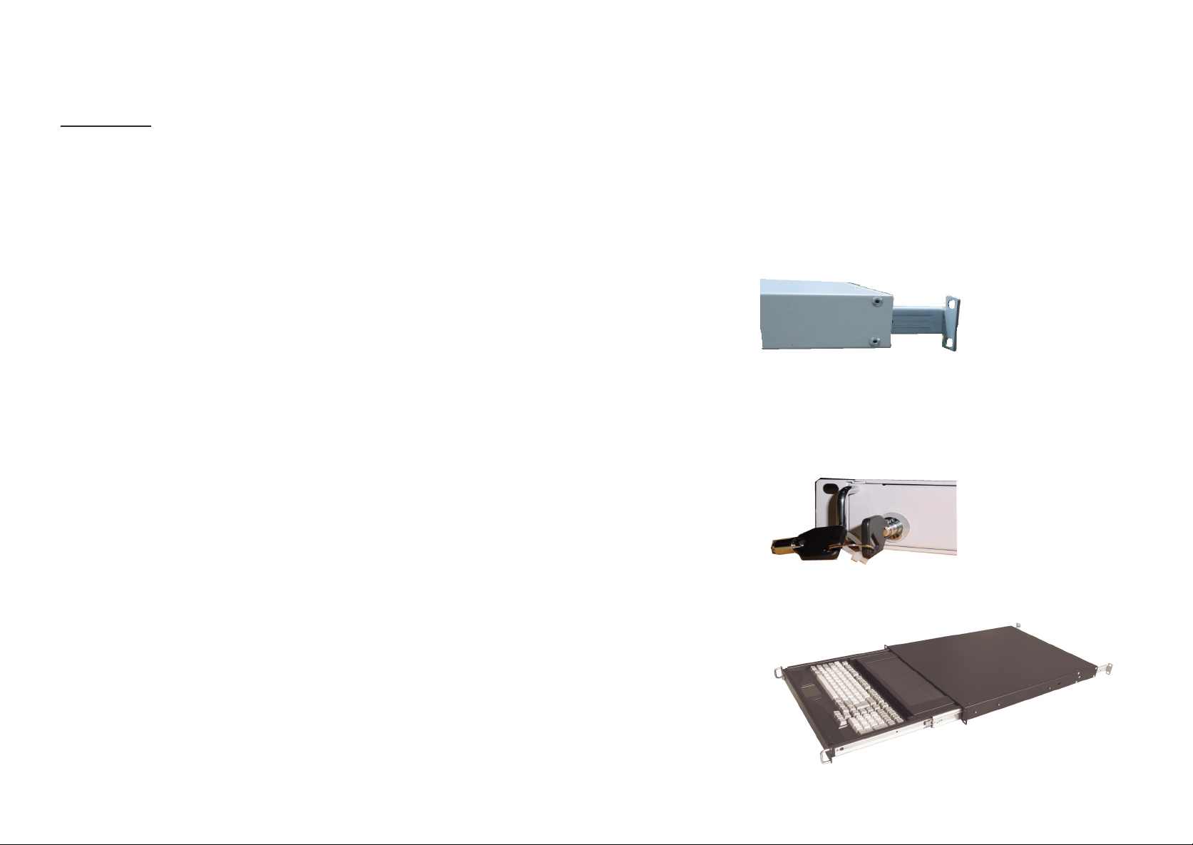
1-1 INSTALLING THE DRAWER INTO A 19” CABINET
1. Fix the front sidepanel ontothe front sideof your 19” cabinet
2. Fix the screws in the back onto the rear side of your 19” Cabinet. The mounting
rails may be adjusted to fit different cabinet depths between 600mm– 750 mm(If
your cabinet depth is over 750mm then please contact us.)
1-2 OPENING THE LCD DISPLAY DRAWER
1. Turn the key clockwise to unlock the LCD/Keyboard drawer.
2. Gently slide the drawer forward out of the rack.
3
4
Page 3
User Manual KVM Terminal LCD
3. Carefully lift the LCD
display into a suitable
viewing position. Now
gently slide the drawer
back to a comfortable
position.
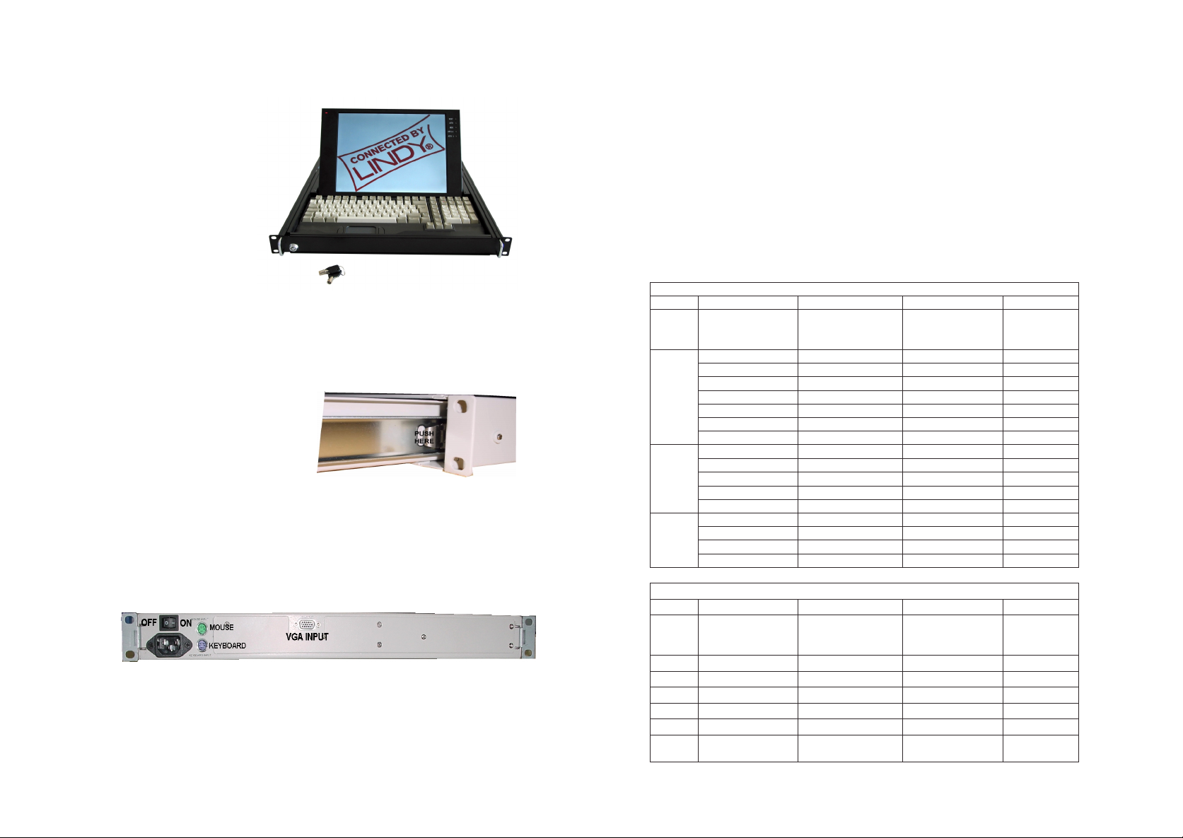
1-3 CLOSING THE LCD DISPLAY DRAWER
1. To close the drawer – pull the drawer forward, and gently fold down the display.
2. While pushing back on the drawer it
will be necessary to press the two
latches on either side of the rails. The
drawercan nowbe pushed backinto
a closed position.
3. Turn the key in an anti-clockwise direction to lock the drawer.
1-4 Cable connections
1. Make sure the Computer or KVM switch you are connecting is turned OFF!
2. Attach suitable cables to the control ports of your computer or KVM switch.
3. Plug the AC powercord.
4. Turn ON the power switch.
5. Turn on the connectedPC or KVM switch
User Manual KVM Terminal LCD
CHAPTER 2 LCD DISPLAY
2-1 Video Input Pin Assignment
The KVM Terminal LCD uses a standard DDC compatible 15-pin VGA connector.
2-2 The Display Timing
Applicable video timing:
The following table lists the display modes best suited for use with the LCD
display. If you choose a video mode which is not listed then this may result in an
unsatisfactorypicture.
VESA MODES
Mode Resolution Nominal
VGA
SVGA
XGA
Mode Resolution Nominal
EGA 640*350@70Hz 31.469 70.086 25.175
CGA 640*400@70Hz 31.469 70.086 25.175
DOS 720*400@70Hz 31.469 70.087 28.322
VGA 640*480@60Hz 31.469 59.940 25.175
XGA 1024*768@72Hz 57.515 72.100 75.000
XGA 1024*768@87Hz
640*350@85Hz 37.861 85.080 31.500
640*400@85Hz 37.861 85.080 31.500
720*400@85Hz 37.927 85.039 35.500
640*480@60Hz 31.469 59.940 25.175
640*480@72Hz 37.861 72.809 31.500
640*480@75Hz 37.500 75.000 31.500
640*480@85Hz 43.269 85.008 36.000
800*600@56Hz 35.156 56.250 36.000
800*600@60Hz 37.879 60.017 40.000
800*600@72Hz 48.077 72.188 50.000
800*600@75Hz 46.875 75.000 49.500
800*600@85Hz 53.674 85.061 56.250
1024*768@60Hz 48.363 60.004 65.000
1024*768@72Hz 56.476 70.069 75.000
1024*768@75Hz 60.023 75.029 78.750
1024*768@85Hz 68.677 84.997 94.500
Interlaced
Horizontal Vertical
Frequency +/-
0.5KHz
Nominal
Frequency +/-1Hz
IBM MODES
Horizontal Vertical
Frequency +/-
0.5KHz
35.522 43.479 44.900
Nominal
Frequency +/-1Hz
Nominal
Pixel Clock
(MHz)
Nominal
Pixel
Clock(MHz)
5
6
Page 4

User Manual KVM Terminal LCD
User Manual KVM Terminal LCD
2-3 The Display Controls
Display Controls
SWITCHNO.
1 RESET
2AUTOCONFIG
3MENU
4 ADJUST (+)
5 ADJUST (-)
1 Reset: Hardware Reset
2 Auto: Auto adjusts the image.
3 Menu: Enter the OSD adjust menu and select the menu.
4 Adjust (+): To scroll up in menu or to increase value of selected item.
5 Adjust (-): To scroll down in menu or to decrease value of selected item.
FUNCTION
2-5 Main Menu
The OSD main menu is displayed on screen when 3 key is pressed. The OSD menu is
a combination of graphicand textdisplay.The bottomline of the mainmenu shows the
current selected or active menu item.
The adjust(+) and adjust(-) keys are used to scroll through items within the menu.The
selected item is highlighted as the scrolling move along. The 3 key is used to close the
sub-menu.
H Position Adjust the horizontal image position
2-4 Screen Adjustment Operation Procedure
1. Entering the screen adjustment
Push the 3 button once to display the main menu of the screen adjustment.
2. Entering the settings
Use the Adjust(+) and Adjust(-) buttonsto select the desiredsettingicon and push the
3 button toenter sub-menu.
3. Changethe settings
After the sub-menu appears, use the Adjust (+) and Adjust (-) buttons to change the
setting values.
4. Save
After finishing the adjustment, select exit icon button to exit and set save "yes", and
then push 3 to save.
5. Return & Exit the main menu
To go back to the previous menu or exit the screen adjustment, push the 3 button and
select exit icon to exit the main menu.
7
V Position Adjust the vertical image position
Clock Adjust the pixel clock
Phase Adjustthe pixel phase
Auto Comfit Auto comfit the clockphase and position
EXPAND Expandthe image
INPUT SELECT Selectthe inputsignalsource
INFORMATION Check the Input information
RECALL Recall EEPROM default
CLR CLEAR EEPROM Set to the factory default
8
Page 5

User Manual KVM Terminal LCD
User Manual KVM Terminal LCD
LINE WRITE Test display
SCALE UP Don'tcare
FLT EDGE FLITER Adjust the image sharpness
MISC FUNC Adjust the image colour
OSD OSD ADJUST Set up OSD position and size
CONTRAST Sets the contrast of the display
BRIGHTNESS Sets the brightness of the display
EXIT EXIT Exit themenuand save
2-6 Horizontal Position
The item "H-Position" is used to adjust the horizontal image position.
A sliderwithcurrentvalueisdisplayed. The rangeof the horizontal
position adjustment valueis 0 to 250.
H-POSITION
0 125 250
2-7 Vertical Position
The item "V-Position" is used to adjust the vertical image position.
A slider with current value is displayed. The range of vertical
position adjustment valueis 0 to 31.
2-8 Clock
The item "Clock” is used to adjust the number of clocks (pixels)
per line (sample per line). A slider with current value is displayed.
CLOCK
0125 250
2-9 Phase
The item "Phase” is used to adjust the ADC sample pixel clock.
A slider with current value is displayed. The range of phase
adjustmentvalue is 0 to 31 f or 0 to 360 degrees.
PHASE
01631
2-10 Auto Configuration
The main menu item "Auto config” is used to perform automatic
configuration of the phase, clock, colour, vertical and horizontal
position. Select sub-menu "Auto adjust” to adjust phase, clock,
colour and position. Select "Auto tracking" to adjust phase and
clock. Select "Auto position" to adjust horizontal and vertical
position. Select "Auto gain" to adjust colour.
V- POSITION
0 125 250
9
AUTO CONFIGURATION
AUTO ADJUST
AUTO TRACKING
AUTOPOSITION
AUTO GAIN
RETURN
10
Page 6

User Manual KVM Terminal LCD
User Manual KVM Terminal LCD
2-11 Expand
The main menu "Expand" is used to adjust display size, select the
sub-menu, zoom "In/Out" to adjust the display size from -15 to 15.
EXPAND
1:1
FULL SCREEN
ASPECT RATIO
ZOOM IN/OUT
RETURN
2-12 Input Select
Pleaseselecttosub-menu "VGA"
INPUT SELECT
VGA
NTSC VISEO IN
PAL VIDEO IN
RETURN
2-13 Information
This item displays VGA Input information.
INFORMATION
1024 x 768 60HZ
HS1PRD : 2035
VS1PRD : 806
HS1PLS : 204
VS1PLS : 6
VTOTAL: 0
SCAN : NINT
VS1POL : NEG
VS1POL : NEG
081aS15 092899
2-14 Recall
The item "Recall" is used to set the LCD to the default values. "Yes" sets
the horizontal, vertical, phase, clock to default values.
RECALL
YES NO
2-15 Clear EEPROM
The item"ClearEEPROM" isusedtosetthe EEPROM to factory
default.
CLR
CLEAR EEPROM
YES NO
2-16 Line Write
This item is used to display colour bar, dot, cross line and H pattern.
Still Mode
MOTION MODE
COLORBAR
DOT x 1
DOT x 2
DOT x 3
CHECK x 1
CHECK x 2
CHECK x 3
HPATTERN
RETURN
11
12
Page 7

User Manual KVM Terminal LCD
User Manual KVM Terminal LCD
2-17 Edge Filter
The main item "Edge Filter" is used to adjust the sharpness of the
display. The range of the adjustmentis -63 to 63.
FLT EDGE FILTER
-63 1 63
2-18 MISC FUNC
MISC FUNC
ADC R GAIN
ADC G GAIN
ADCBGAIN
ADCR OFFSET
ADCG OFFSET
ADCB PFFSET
RETURN
ADC R GAIN (Analog / Digital Converter Gain Settings)
Theitem "ADC R GAIN” is used to adjustthe gainof red channel
in ADC. The rangeof the adjustment valueis 0 to 255.
ADC G GAIN
Theitem"ADCGGAIN”isusedtoadjustthegainofgreen
channelin AD C. The rangeof he adjustmentvalue is 0 to 255.
ADC B GAIN
Theitem"ADCBGAIN”isusedtoadjustthegainofbluechannel
in ADC. The range of the adjustment value is 0 to 255.
2-19 OSD Adjust
OSD
OSD H Position
The item "OSD H Position” is used toadjust the OSD menu
horizontalposition. The rangeof the adjustmentvalueis 0 to255.
OSD V Positio n
The item "OSD V Position” is used to adjust the OSD menu
verticalposition. The range of the adjustmentvalue is0 to 255.
OSD Blending
The item "OSD Blending” is used adjust the appearance of the OSD
menu. There are four steps for selection.
OSD Font Size
The item "OSD Font Size" is used adjust the size of the OSD
menu. There are four steps for selection.
OSD ADJUST
OSD H POSITION
OSD V POSITION
OSD BLENDING
OSD FONT SIZE
RETURN
2-20 Contrast
The mainmenu item"Contrast"is usedtoadjust thecontrast
of the panel. A slider with current contrast value is displayed.
The range of contrast adjustment value is 0 to 255.
ADC R OFFSET
The item " ADC R OFFSET” is used to adjust the offset of red
channelin AD C . The rangeof theadjustment valueis 0 to 63.
ADC G OFFSET
The item "ADC G OFFSET” is used to adjust the off set of green
channelin AD C . The rangeof theadjustment valueis 0 to 63.
ADC B OFFSET
The item "ADC B OFFSET” is used to adjust the off set of
blue channel in ADC. The range of the adjustment value is 0 to 63.
13
CONTRAST
0 128 255
14
Page 8

User Manual KVM Terminal LCD
E
g
w
RadioFrequency Energy, Certifications
2-21 Brightness
The main menu item "Brightness" is used to adjust the brightness
of the panel. A slider with current brightness value is displayed.
The rangeof brightnessadjustmentvalue is 0 to 255.
BRIGHTNESS
0 126 255
2-22 EXIT
Exitthemenu and save.
EXIT
EXIT
YES NO
Shielded cables must be used with this equipment to maintain compliance with radio frequency
energy emission regulations and ensure a suitably high level of immunity to electromagnetic
disturbances.
uropeanEMC directive 89/336/EEC
CE statement
Thisequipment complieswith the requirement for
CE mentioned in the European Directiveand
Standards EN55022 and EN55024.
This equipment has been tested and found to
comply with the limits (for a class B computing
device)in accordance with the specificationsin the
European Standard EN55022. These limits are
designed to provide reasonable protection against
harmful interference. This equipment generates,
uses and can radiateradiofrequency energy and if
not installed and used in accordance with the
instructions maycause harmful interference to
radio or television reception. However, there is no
uaranteethat harmful interference will not occur in
a particularinstallation.If this equipment does
causeinterferenceto radioor television reception,
hich can bedetermined by turning the equipment
on and off, the user is encouraged to correct the
interference with one or more of the following
measures: (a) Reorient or relocate the receiving
antenna. (b) Increase the separation between the
equipmentand the receiver.(c) Connectthe
equipmentto an outlet on a circuit different from
that to which the receiveris connected. (d) Consult
the supplier or an experiencedradio / TV
technician forhelp.
FCC Compliance Statement (United States)
This equipment has been tested and found to comply
withpart 15 of FCC rules.
Operation is subject to the followingtwo conditions:
(1) This device may not cause harmful
interference.
Thisdevicemust accept any interferencereceived.
Including interference that may cause undesired
operation.
Canadian Department of Communications RFI
statement
This equipment does not exceed the class B limits for
radio noise emissions from digital apparatus set out in
the radio interference regulations of the Canadian
Department ofCommunications.
Le présent appareil numérique n’émet pas de
bruits radioélectriques dépassant les limites
applicables aux appareils numériques de la
classe A prescritesdans le règlement sur le
brouillage radioélectriquespublié par le ministère
des Communications du Canada
15
© LINDY ELECTRONICS LIMITED & LINDY-ELEKTRONIKGMBH - FIRST EDITION (AUG 2002)
 Loading...