

Page 1
Specications
LiN76
Vintage Limiting Amplier
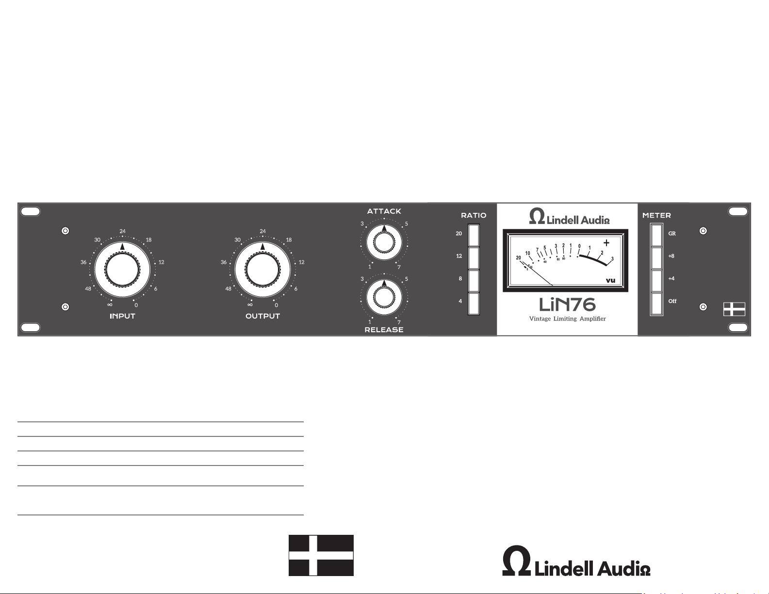
Attack Continuously variable 20uS to 800uS
Release Continuously variable 50mS to 1200mS
Ratio Pushbutton selected 4:1, 8:1, 12:1, 20:1 and any combination
Voltage 12VAC
AC Mains Input 100V-240V depending on supplied
Dimensions Width 438mm (19”)
Weight 8kg
©2022 Lindell Audio. This manual and any associated intellectual property are subject to copyright protection.
No part of this document may be reproduced in any form without explicit written consent from Lindell Audio.
Height 88mm (2U)
Depth 250mm
Page 2
Important Safety Instructions
1. Read these instructions.
2. Keep these instructions
3. Heed all warnings.
4. Follow all instructions.
5. Do not use this apparatus near water.
6. Clean only with dry cloth.
7. Install in accordance with the manufacturer’s
instructions.
8. Do not install near any heat sources such
as radiators, heat registers, stoves, or other
apparatus that produce heat.
9. Protect the power cord from being walked on
or pinched particularly at plugs, convenience
receptacles, and the point where they
exit from the apparatus. If the power cord
becomes frayed, stop using immediately.
10. Use only attachments/accessories specied
by the manufacturer
11. Use only with a cart, stand, tripod, bracket
or table specied by the manufacturer, or
sold with the apparatus. When a cart is used,
use caution when moving the cart/apparatus
12. Unplug this apparatus during lightning storms
13. Refer all servicing to qualied service
14. This apparatus shall not be exposed to
15. Note that this apparatus is not completely
16. The mains plug or power inlet on the product
combination to avoid injury from tip-over.
or when unused for long periods of time.
personnel. Servicing is required when
the apparatus has been damaged in any
way, such as power supply cord or plug is
damaged, liquid has been spilled or objects
have fallen into the apparatus, the apparatus
has been exposed to rain or moisture, does
not operate normally, or has been dropped.
dripping or splashing, and no object lled with
liquids, such as vases, shall be placed on the
apparatus.
disconnected from the AC mains service when
the power switch is in the OFF position.
is used as the disconnect device, so the
disconnected device shall remain readily
operable when reconnected.
17. Any changes or modications not expressly
approved in this manual could void your
authority to operate this apparatus.
Important !
Be sure to only use the supplied 12V AC supply
with this unit. Other supplies can potentially
damage the unit.
The lightning ash with an arrowhead symbol
within an equilateral triangle is intended to alert
the user to the presence of uninsulated “dangerous
voltage” within the product’s enclosure that may
be of sufcient magnitude to constitute a risk of
electric shock to persons.
The exclamation point within an equilateral triangle
is intended to alert the user to the presence of
important operating and maintenance (servicing)
instructions in the literature accompanying the
product.
The Lindell Audio LiN 76 complies with all
applicable / RoHS/ WEEE European Union
directives.
Do not attempt to service this unit yourself, as it
will void your warranty. Please check your unit
carefully upon receipt and return to place of
purchase immediately if there are any problems
with the product. After that, the standard Lindell
Audio 3 YEAR warranty will apply to defects in
materials and workmanship.
International Service
For service or warranty assistance, please
contact the Lindell Audio distributor in
your country through the dealer from
whom you purchased this product.
Limited 3 Year
Warranty
Lindell Audio’s LiN76 is warranted by Lindell
Audio to be free from defects in materials
and workmanship for the period of THREE (3)
YEARS to the original purchaser. In the event
of such defects, the product will be repaired
without charge or, at our option, replaced
with a new one if delivered to Lindell Audio
prepaid, together with a copy of the sales slip
or other proof of purchase date. The warranty
excludes problems due to normal wear, abuse,
shipping damage or failure to use the product
in accordance with the specications.
All parts and labor are covered under this Limited
Warranty. However, if it is determined by Lindell
Audio that the device was damaged or made
defective through abuse, we reserve the right to
charge the customer for the cost of the repair.
Lindell Audio shall not be liable for damages based
upon inconvenience, loss of use of the product,
loss of time, interrupted operation or commercial
loss or any other damages, whether incidental,
consequential or otherwise. This warranty gives
you specic legal rights, and you may have other
rights, which will vary from state to state.
This warranty is not transferable.
Quick Start Guide
On your sound system, mute your monitors and
then using balanced TRS cables, connect your
LiN 76 to your mixing bus or patch bay. Set all
controls to full counter-clockwise position, and
all pushbuttons deselected or in the off position
make sure that no ratios are selected. Set the
OFF button to the deseleted (vu meter will
turn on) position, and apply power. Unmute
the monitors, and verify that signal is passing to
and from the unit. Set the Input, Output, Attack
and Release controls to about 12 o’clock, select
Ratio 4, and press the GR pushbutton. Increase
the Input until the meter is deecting a few
dB. Again, verify signal is passing through the
unit. At this point that the unit is functioning
correctly. If you would like the compressor to
compress more increase the input knob. This
will allow more signal into the compressor
and cause the compressor to react more. If you
would like the compressor to compress more
with the same amount of signal input, increase
the ratio. Ratios can be selected by pressing one
button at a time OR combinations of different
buttons at the same time.
All Button Mode
By pressing in all 4 buttons you active what
is referred to as “all button” mode. This “secret
mode” changes the ratio to roughly 20:1. It also
changes the bias of the circuit and the way that
the knobs interact with each other. The unit will
become much more aggressive with its reaction
knee becoming more like a plateau than a gentle
curve and will have a more aggressive dirty tone
that sounds incredible on aggressive drums. The
attack will become very punchy with a gooey
“sucking” sound on the release.
Favorite Setting
While there is no proper way to use a
compressor (please experiment and get
creative!) there are certain settings that we do
personally suggest for certain sources. The
most popular use would be vocals and we nd
that a relatively mild input signal of about 3630 should cause gentle compression for vocals,
creating a thickening effect without crushing
the audio. Then use the output control to bring
the vocals back up to the orginal volume level.
Setting the attack to roughly 9 o’clock and the
release to about 3 o’clock with give it a natural
sound without sounding articial.
Meter Calibration
Making sure that the meter returns to zero is
important to the compressors functionality.
This is controlled the the mater calibration set
screw on the back of the unit. Set the meter to
GR and make sure that no ratios are selected by
pressing in any ratio button just enough that all
4 pop out. Then using a athead screwdriver,
rotate the screw on the rear panel until the
needle rests on 0. Voila! Meter calibrated.
2 3 4
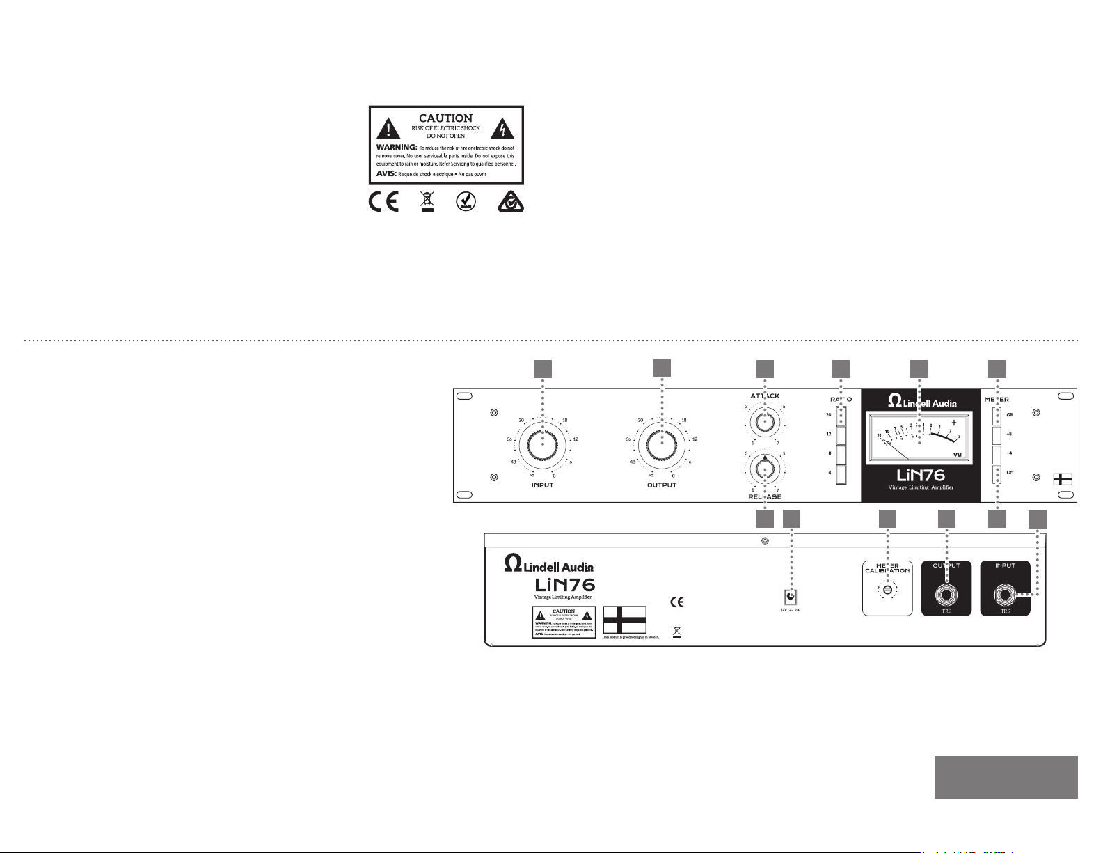
1. Power Button: turns the unit off.
When gr, +4 or +8 are selected,
the unit is on.
2. Input: Sets the threshold and
controls the level at which the
compressor starts compressing.
Louder signal will require less input to trigger the same amount
of compression than softer
sounds.
3. Output: Applies makeup gain to
compressed signal to compensate for signal lost during compression
4. Attack: Controls the amount of
time it takes for the unit to react
to an incoming signal. Continuously variable from 20uS to
800uS
5. Release: Controls the speed at
which the compressor releases
the compressed signal. Continuously variable 50mS to 1200mS
6. Ratio: Controls the amount of
compression applied (Yes, it does
all-buttons-in-mode). The higher
the ratio, the more compression
is applied for the same amount
6 8
5 1
9 10 11
of signal inputted once compression is triggered.
7. VU Meter: Displays units select-
ed by Meter Mode.
8. Meter Mode: Selector switches
GR meters the amount of gain
reduction applied (+4 meters
7
trol to adjust the 0 resting point
when no compression is being
applied.
11. TRS Output: Balanced line-level
output
12. TRS Input: Balanced line-level
input.
output level at 0 with +4dB output; +8 meters output level at 0
with +8dB output)
9. AC Adapter Input: ONLY use
the supplied 12VAC to power
Note: For proper
performance, balanced
TRS must be used for all
inputs and outputs.
this unit.
10. Meter Calibration: Use this con-
12
 Loading...