

Page 1
lindab | we simplify construction
LindabUltraLink® Monitor
FTMU
Technical information
Page 2

Content
Introduction .................................................................................................... 2
Overview ........................................................................................................3
Description .....................................................................................................3
Planning ..........................................................................................................4
Mounting ........................................................................................................6
Connections ................................................................................................... 6
Power supply ..................................................................................................8
Display ............................................................................................................ 9
Settings ..........................................................................................................9
ID-numbers .................................................................................................. 12
Troubleshooting ........................................................................................... 12
Maintenance ................................................................................................. 12
PIN code ....................................................................................................... 12
Technical data .............................................................................................. 13
Airflows ......................................................................................................... 13
Appendix A – Modbus register .................................................................... 14
Introduction
UltraLink® FTMU is a highly accurate flow monitor without any obstacles in the
airstream that creates pressure drop. It measures the flow with an angled ultrasonic
beam which can be calculated and compensated to a very high accuracy over the
whole flow range. The method is very stable over time due to that it is not sensitive
to dirt and the design minimizes the dust accumulation on the flow sensors.
An increased focus on energy saving has led to ventilation systems requiring low
minimum flows. The low flows are a problem since they are very difficult to measure, which makes it difficult to control the ventilation system.
The new technology of UltraLink
compared to today’s products while maintaining measurement accuracy. This
offers great advantages for the user in terms of comfort and savings in energy
consumption, which is of great interest.
2
®
makes it possible to measure lower air flows
We reserve the right to make changes without prior notice We reserve the right to make changes without prior notice
Page 3
Overview
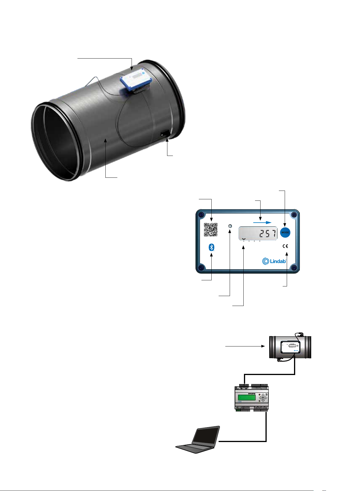
Display unit
Flow sensor
Sensor body
Description
Application
The Monitor is suitable for measuring air flow and temperature. Communication is established via analog or digital
signal using Modbus.
Design
The Monitor consists of a sensor body with Lindab Safe
gaskets.
Two flow sensors are mounted on the sensor body and
connected to a display unit. The display unit is mounted
ontop of a shelf on the sensor body. Since the display
and shelf is mounted on the sensor body using a sheet
metal strap, the display unit can be rotated relative to the
sensorbody.
Display unit
QR code
Lindab UltraLink
Monitor FTMU
Bluetooth
logotype
®
Status light
Display parameters
Air flow
direction
Mode button
Air flow direction
Status Airflow
m³/h l /s m/s °C
IP classification
CE-mark
IP42
Patented
IP42
Monitor FTMU
Airflow
Status
°C
m³/h
Mode
m/s
l/s
Positioning the sensor body correctly after a disturbance
is crucial for the measurement accuracy, see page 4 for
directions on how to mount the Monitor for optimal performance.
Note! The flow sensors are placed at a fixed distance
to each other and they shall never be removed and
not used as handles when turning the sensor body.
We reserve the right to make changes without prior notice
RTU
TCP/IP
3
Page 4
Planning
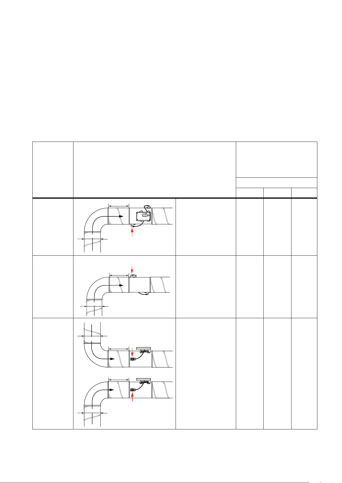
The longer distance to disturbance, i.e. the longer straight duct before the Monitor, the higher the measurement accuracy
will be. However this is not the only factor which affects the accuracy of the measurement. The rotation of the Monitor and
hence the positioning of the first flow sensor has an impact on the uncertainty of the measurement. It is not recommended to mount the Monitor so that the first flow sensor (*) is placed on an outer radius of a fitting.
For example: in the case of the bend in the table below, by rotating the Monitor to position the first flow sensor according
to the first picture (with the first flow sensor on the inner radius of the bend), the Monitor can be placed at the distance
of two duct diameters from the disturbance to achieve 5 % uncertainty. Positioning the Monitor according to the second
picture (with the first sensor on the outer radius of the bend), the Monitor must be mounted five duct diameters from the
disturbance to achieve the same level of uncertainty.
Never use an UltraLink
it must be placed on the outlet side. Minimum straight distance after Monitor is 1×Ød.
Disturbance * Placement of first flow sensor
Bend
®
on the outlet side of a duct fan. Place it on the inlet side or in worst case use a flow conditioner if
a
Inner radius
Ød
*
*
a
Bend
Outer radius
(Not recommended)
Measurement uncertainty
± % or X l/s depending wich is
the greatest, where X equals
the diameter in dm, see table
on page 13.
a
2-4·Ød >4-5·Ød >5·Ød
5 5 5
20 10 5
Bend
4
Ød
Ød
Ød
a
*
a
Side
10 5 5
*
We reserve the right to make changes without prior notice We reserve the right to make changes without prior notice
Page 5
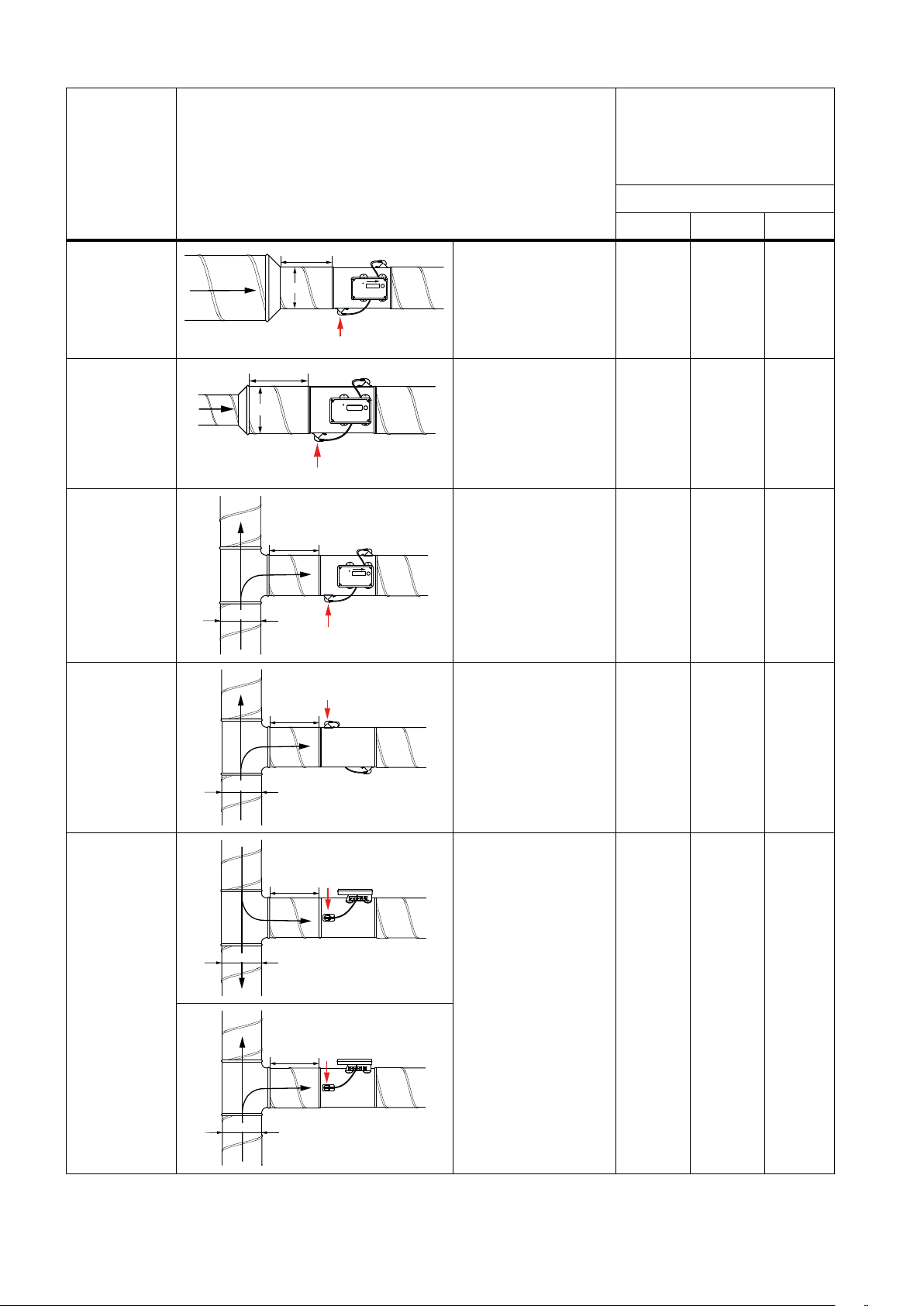
Measurement uncertainty
*
± % or X l/s depending wich is
the greatest, where X equals
the diameter in dm, see table
on page 13.
a
Disturbance * Placement of first flow sensor
a
Reducer
Ød
a
Ød
Reducer
a
T-pi e c e
Ød
Duct diameter
decrease
Duct diameter increase
Inner radius
2-4·Ød >4-5·Ød >5·Ød
5 5 5
10 5 5
10 5 5
T-pi e c e
T-pi e c e
Ød
Ød
Ød
*
a
Outer radius
(Not recommended)
a
*
Side
a
*
20 10 5
10 5 5
We reserve the right to make changes without prior notice
5
Page 6
Mounting
Mount the Monitor into the air duct system according to
the mounting instructions for Lindab Safe. Do not use
the flow sensors as handles when you mount the
Monitor since this may cause damage and changes
in their positions might effect the measurement
accuracy.
Make sure the airflow arrow is pointing in the direction of the airflow.
Note the ID-number of the Monitor. The ID can be found
on the label of the box it was delivered in or on the label
on the Monitor itself and are the three last numbers of the
serial no.
Position the Monitors sensor body according to the chapter ”Planning”, loosen the screw on the steel strip holding
the display unit in place. Rotate the display unit so that
the display is visible from some direction. For future connections it is important that the screws on the lid of the
display can be removed. Tighten the screw on the steel
strip so that the display unit is fixed to the sensor body.
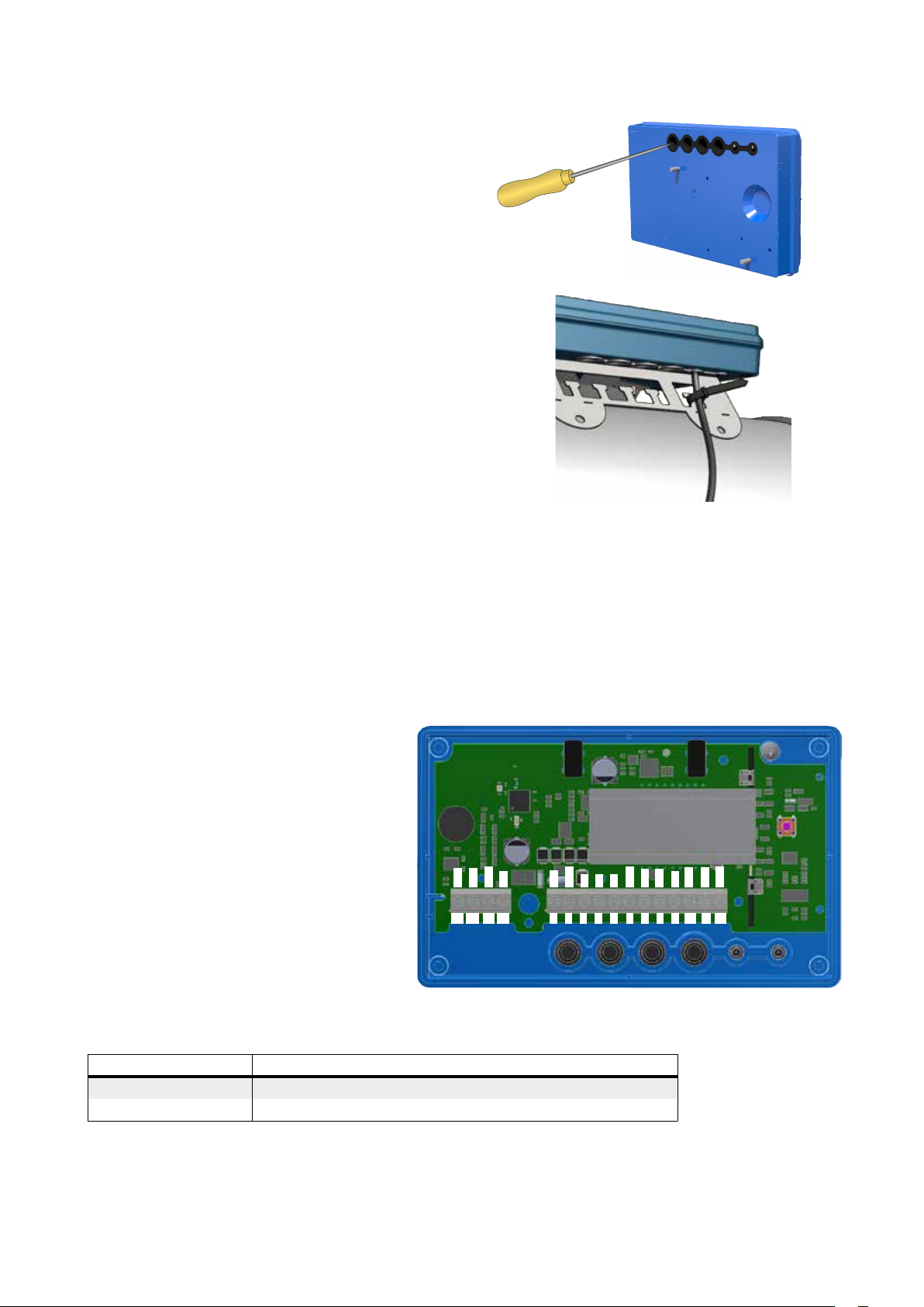
To be able to connect cords to the terminal board the rubber cable grommet on the backside of the display unit must be
punctured, preferably using an awl or something else pointy to ensure tightness to the environment. When the cords have
been connected they must be strain relieved. The cords can be attached to the shelf by using cable ties that are attached
around cut outs in the shelf.
You must under no circumstances make any holes or connect anything with screws to the sensor body since this will
have an impact on measurement accuracy!
Connections
Connect the Monitor to a remote terminal unit using RS485 or analog terminals. Connections are made in the terminal
board which can be accessed when the lid of the display unit is removed.
1. 24V, power supply (AC G, DC +) *
2. GND, power supply (AC G0, DC -) *
3. +B, connection for Modbus via RS485
4. -A, connection for Modbus via RS485
5. SH, shield
6. GND, ground (system neutral)
7. AO1, analog output
8. AO2, analog output
9. AIN, (not used in this version)
10. MO1, (not used in this version)
11. MO2, (not used in this version)
12. GND, ground (system neutral)
13. SCL, not used
13
SCL
14
SDA
GND
1615
3V3
123
14. SDA, not used
15. GND, ground (system neutral)
16. 3V3, not used
*) When using AC terminal 1 (G) should be system potential and terminal 2 (G0) should be system neutral.
Recommendations for wiring:
24V
GND
+B
-A
4 5
SH
GND
AO1
AIN
MO1
MO2
101112
GND
AO2
6
9
7
8
Function Cable type
24 V Supply 2-wire, thickness depending on length and load, max. 1,5 mm²
RS485 2-wire shielded twisted pair, min. 0,1 mm² (LIYCY cable)
Supply the Monitor with power from a transformer.
6
We reserve the right to make changes without prior notice We reserve the right to make changes without prior notice
Page 7
B A
+B -A +B -A +B -A
+B
-A
SH SH SH SH
GND
Digital connection
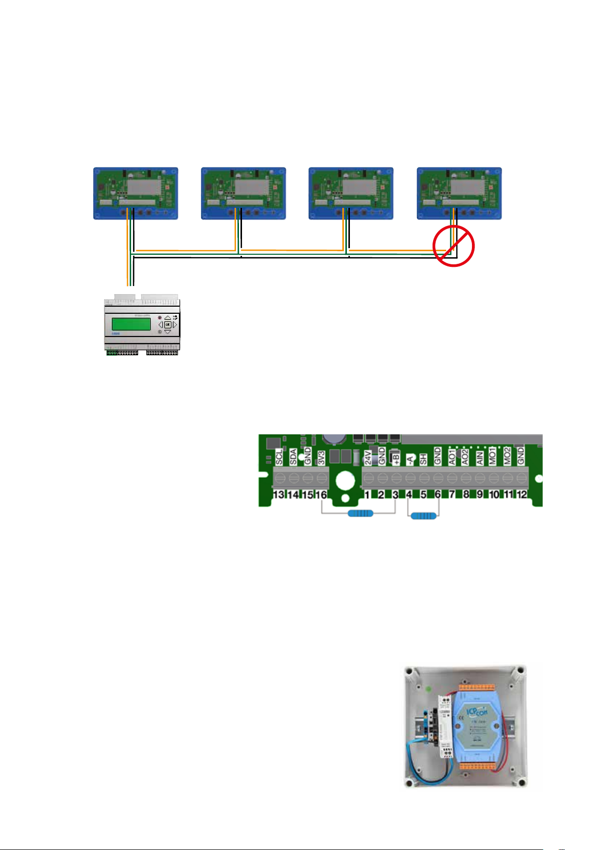
Connect A on the RTU to -A on the display unit and B to +B. When connecting more than one Controller in series it is
important to keep connecting -A to -A and +B to +B since crossing them will stop Modbus from working. The shield in
the RS485 cable should be connected to ground at the transformer and then continuously connect to ”SH” on all the
UltraLinks that are powered from that transformer. If more than one transformer is used on the bus, the shield is broken
at each transformer so ”SH” on every product only has connection to ground at the transformer from which it’s power is
supplied. It is recommended to use RS485 cables with twisted pairs and shield, do not supply power in the same cable
unless the cable is produced for that purpose.
Biasing
The master on the bus must have biasing on -A and +B. This is more or less standard on BMS-controllers, but if communication should be established with a conventional computer using a RS485-USB converter, then it is important to make
sure that the converter has a bias circuit. If communication fails and you are uncertain about existance of biasing, you can
add biasing resistors in the screw terminal on one of the UltraLinks to see if this is the cause of the communication failure.
Use 500 - 1000 Ω resistors and connect one
resistor from -A to GND and one from +B to the
3V3 terminal. It is also recommendedto add a 120
Ω termination resistor between -A and +B on the
last UltraLink on the bus to avoid signal reflections.
Analog connection
When connecting the Monitor using analog signals, it is important to connect the analog out signals on the Controller
(AO1, AO2) to the analog in terminals on the RTU and the analog in signal (AIN) is connected to the analog out terminal on
the RTU. Also make sure to connect the cables to the same analog ground.
Bluetooth® connection
If the product is equipped with Bluetooth (the Bluetooth logotype is printed on the displayunit), wireless communication
with the UltraLink can be established. Using a smartphone or tablet with the Lindab UltraLink App, nearby UltraLinks
can be identified. It is then possible to connect to one unit and view information regarding that UltraLink, such as active
measurements and settings.
Mobile app
The app “UltraLink” is available on both Android and iOS, it’s free to download from
Google Play or App store. Like the PC configuration tool, all settings can be changed
via the app. This means all settings can be individually chosen for the specific building,
it is therefore necessary to protect the unit with the PIN code in the UltraLink menu.
For a discription on how this is done, see page 9.
Repeater
If the bus is longer than 300 meters or if there are more than 30 devices, the system
might need an RS485 repeater (FDS-R, see picture to the right) to be able to communicate in an efficient way.
We reserve the right to make changes without prior notice
7
Page 8
Power supply
Transformer sizing
Power consumption
The needed size of 24 V AC transformer(s) can be defined
by adding up the dimensioning power consumption [VA]
of all the components. The transformer power must
exceed this. Use only safety isolating transformers. Calculation of the current demand I:
I = (P1+P2+…+P
) / U [A]
n
where:
P
is the dimensioned power consumption for each com-
n
ponent [VA] U is the voltage (24) [V].
If the current demand I exceeds 6 A ( which corresponds
to approximately 150 VA for a 24 V AC transformer ), it is
necessary to use more transformers to prevent overheating.
Supply cable sizing
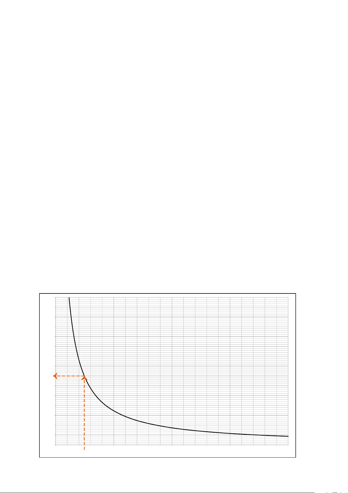
The wire size of the supply cable can be determined by
calculating the resistance per meter R. The calculation
presupposes that a voltage drop of e.g. 2 V is accepted in
the supply cable:
R(per m) = U
where:
U
is the accepted voltage drop (2 V) in the cable [V] I is
drop
the current [A]
L is the longest distance of supply cables from transformer to a component [m]
/ (I * L) [Ω/m]
drop
The power consumption for dimensioning supply cables
for an UltraLink
®
Monitor is 0,5 VA.
It is not recommended to use a transformer with a
higher capacity than 150 VA!
Example:
U
= 2 V, I = 4 A, L = 20 m
drop
R (per m) = 2V / (4A × 20 m) = 0,025 Ω/m
In the diagram a Wire cross section Area of 0,7 mm² can
be read.
Wire cross section area as a function of resistance per m for copper wire
1,5
1,4
1,3
1,2
1,1
]
2
1
0,9
0,8
0,7
0,6
Wire cross section Area [ mm
0,5
0,4
0,3
0,2
0,1
0
Copper Resistance [ Ω/m ]
0,100,050
0,15
0,20
8
We reserve the right to make changes without prior notice We reserve the right to make changes without prior notice
Page 9
Display
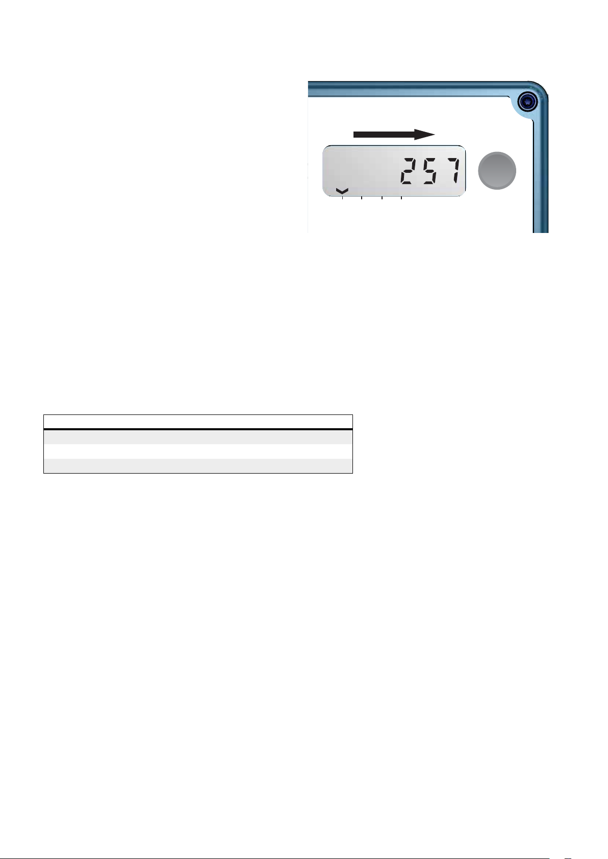
The display can show useful information both with the
diode flashing in green (status light) and with parameters
in the LCD. If the product is equipped with Bluetooth, then
the diode will also flash in blue every three seconds. If a
device has been connected to the UltraLink via Bluetooth,
then the diode will flash in blue every other second. By
short pressing the mode button you can change the displayed parameter. If the button is pressed for more than 5
seconds (long press) then the configuration menu will be
visible. The arrow at the bottom of the display indicates
the current parameter type and unit.
The following parameters can be shown:
• Air flow (m³/h)
• Air flow (l/s)
• Air velocity (m/s)
• Temperature (°C)
• Monitor’s ID number
The standard setting for the display shows the air flow in
m³/h.
For a detailed description on configurating the UltraLink
using the mode button on the display, see page 11.
Airflow
m³/h
l/s
m/s
°C
Mode
Status light
The status light indicates:
Mode Function
No light Monitor is turned off
Flashing light A problem has occured
Constant light Monitor is turned on and functioning as normal
We reserve the right to make changes without prior notice
9
Page 10
Settings
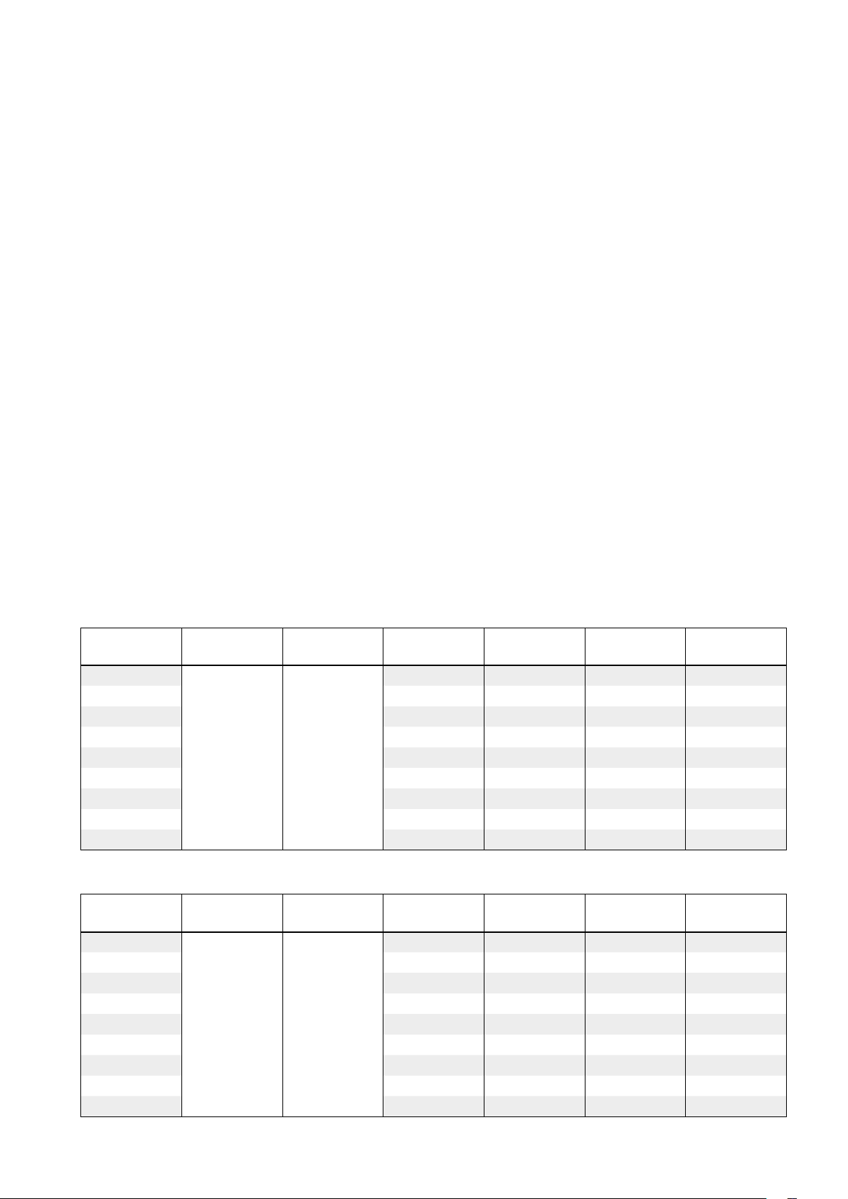
All available settings are presented in the appendix. These can be changed via a Bluetooth device and an app, which can
downloaded from Google Play or App Store. The settings can also be changed via the RS485 bus and can be done from
any device and configuration that can communicate using Modbus, but preferably the UltraLink
separate documentation). Instructions for the most common settings are described below. For more register details see
appendix.
Digital communication settings
Registers 4x001-4x009 are used to configure communication settings. When initializing contact for the first time the
default settings will be active;
Modbus id: Last three digits in the serial number (also visible in the display if the product has power)
Baud rate: 19200
Parity: Odd
Stop bits: 1
®
Configuration tool (See
After updating any of the communication parameters the product needs to be power cycled for the changes to take eff
ect. If communication fails with the default parameters selected in the UltraLink
®
configuration tool, then the communication settings on the Monitor might have been changed previously. Verify the settings in the display (See page 11 for
instructions)
Analog out settings
Analog out is always active but you need to specify what kind of data you want to read on the two ports;
1. Configure registers 4×401 and 4×431 for the variables you want to read on the analog out terminals (0 = Flow, 1 = Tempe-
rature).
×
2. Configure registers 4
3. Configure registers 4
step 2. You only need to configure the max and min values corresponding to the variable selected in step 1.
Size Ø
[mm]
100
125 0 50 0 86
160 0 50 0 141
200 0 50 0 220
250 0 50 0 344
315 0 50 0 546
400 0 50 0 880
500 0 50 0 1374
630 0 50 0 2182
400 and 4×430 for analog out level configuration ( (0) 0-10V, (1) 10-0V, (2) 2-10V, (3) 10-2V)
×
401–406 and 4×431–436 with relevant data for max and min levels for the voltage range selected in
4x400
Level Conf.
4x401
Unit Conf.
4x402
Temp Min [°C]
4x403
Temp Max[°C]
4x404
Flow Min [l/s]
Flow Max [l/s]
0 50 0 55
2 ( 2-10V ) 0 (Flow)
4x406
Default values for the relevant registers related to “Analog Out 2” are according to the table below (Default values for flow
max corresponds to 7 m/s).
Size Ø
[mm]
100
4x430
Level Conf.
4x431
Unit Conf.
4x432
Temp Min [°C]
4x433
Temp max[°C]
4x434
Flow Min [l/s]
0 50 0 55
4x436
Flow Max [l/s]
125 0 50 0 86
160 0 50 0 141
200 0 50 0 220
250 0 50 0 344
2 ( 2-10V )
1 (Tempera-
ture)
315 0 50 0 546
400 0 50 0 880
500 0 50 0 1374
630 0 50 0 2182
10
We reserve the right to make changes without prior notice We reserve the right to make changes without prior notice
Page 11
Configuration menu structure
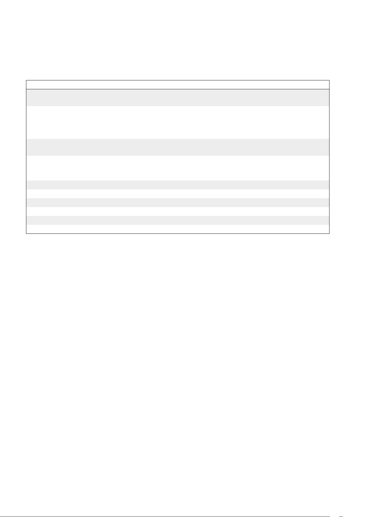
The settings that are related to RS485 communication can also be set via the display. The configuration menu is activated
by long pressing the button (5 sec). After long pressing the button the first menu option appears in the display. Toggle to
the next menu tag by short pressing the button. Long press to change the setting for the shown menu tag. All menu tags
and options are shown in the table below;
Menu tag Description Options Description
• Pr. Protocol Pr.PAS
Pr.Mod
• b. Baud rate b.9600
b.19 2 0 0
b.38400
b.76800
• bit. Stop bits b it.1
bit.2
• P. Parity P.o d d
P.e v e n
P.none
• Id. Modbus Id Id.x Modbus id (x = value) *)
• PLA. PLA address for Pascal PLA.x PLA address (x = value) *)
• ELA. ELA address for Pascal ELA.x ELA address (x = value) *)
• Pi. Pin-code Pi.xxxx Def a u l t : x x x x = 1111
• Store Store changes Strores changes on long press
• Cancel Cancel Cancel and ignore changes on long press
Pascal protocol
Modbus
Baud rate 9600
Baud rate 19200
Baud rate 38400
Baud rate 76800
1 stop bits
2 stop bits
Odd parity
Even parity
Parity none
*) To change the value you need to long press until a blinking cursor appears under the first single number in the current value.
After that you short press to toggle to the desired number, then you long press to move the blinking cursor to the
number in the current value. Proceed until the new value has been set and long press to continue.
PLEASE LOOK IN THE APPENDED MODBUS REGISTER FOR INSTRUCTIONS ON HOW TO CHANGE REGISTER
VALUES. SOME VALUES HAS SCALE FACTORS AND SOME VALUES OCCUPY TWO REGISTERS!
next single
PIN code
UltraLink® with Bluetooth must be protected againt unauthorized access by PIN-code, which has to be stated before
changes to the settings can be made. It is important to choose and change the code that the product is delivered with
(1111), to ensure that no unauthorized changes are made.
The code can be changed in three ways:
• using the configuration menu in the display, see page 11 for instructions.
• connecting a PC via Modbus and using the ”Configuration Tool” software.
• connect a Bluetooth device and use the ”UltraLink” application.
We reserve the right to make changes without prior notice
11
Page 12
Monitor FTMU Ø125
Serial no. 132600052
UltraLink
Lindab
®
ID-numbers
The monitors have from production been given an
ID-number between 1 to 239. The given ID-number can
be seen on the label on the outside of the box the monitor
is delivered in, the ID-number is the same as the three last
digits in the serial number.
If two or more monitors have the same ID-number it is
necessary that each of them get an unique ID-number to
allow communication.
To change the Modbus ID register of an UltraLink
®
all
other devices with the same ID must be disconnected.
It is more efficient to change the ID in the display under
“Con.Set” (See page 9 for more info). The register for
Status
Airflow
Modbus ID is a holding register with address 4x001.
Troubleshooting
m³/h
°C
m/s
l/s
Mode
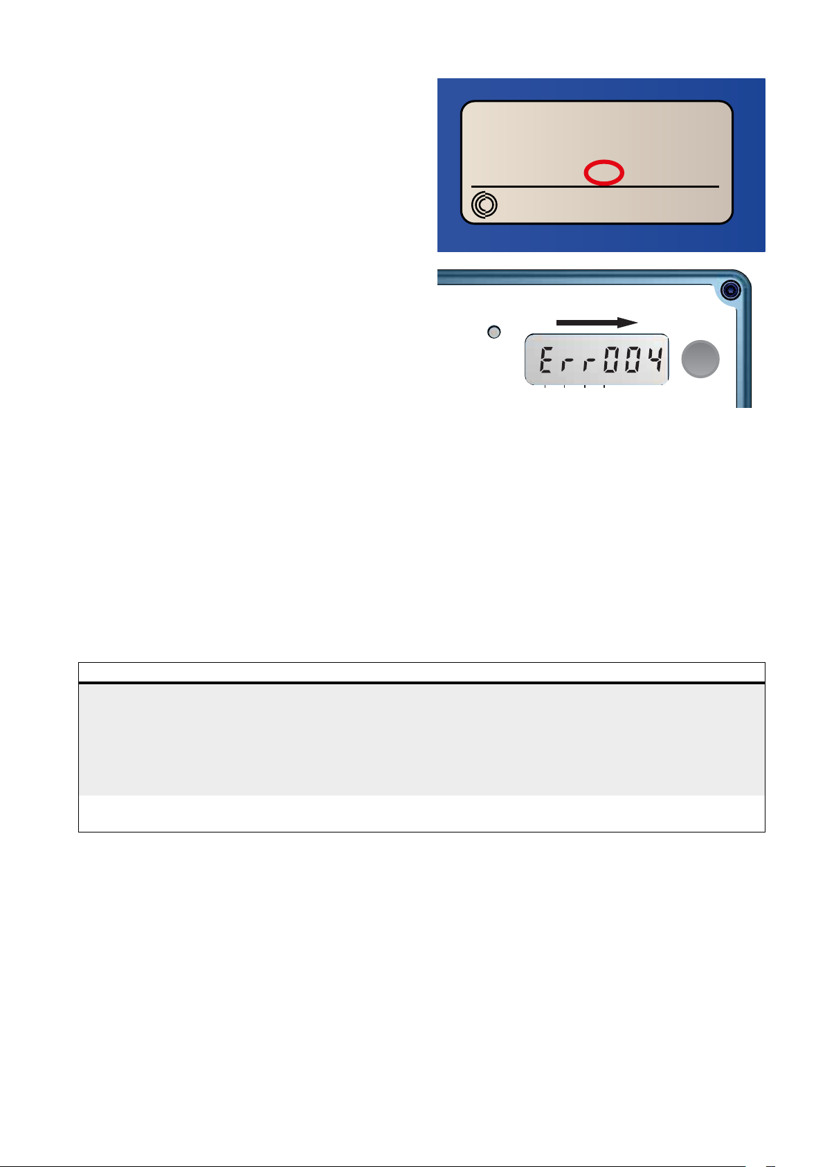
If a problem occors the status light will start to flash and an
error code will be displayed.
If communication fails, please verify the following before contacting support:
• Check settings for Baud rate, parity and stop bit and make sure the master uses the same settings as the UltraLinks.
• -A and +B are continuously connected between all the products without any mixups of -A and +B. Star connection is
not allowed.
• The cables for power supply are connected identical on all products and transformers connecting G to G (24V) and
G0 to G0 (GND).
• The shield is continuous along the bus and grounded only at the transformer and the last UltraLink on the bus.
• There are not more than 30 devices on the bus. (Try a repeater if you have more than 30 devices.)
• The total length of the bus is maximum 300 m. (Try with a repeater if you have more than 300 m bus cable.)
• Try to establish communication with a PC using Control Center and a biased RS485-USB converter.
Error code Problem Comment
Err004
Err032
Maintenance
Normally does not require any maintenance.
The visible parts of the device can be wiped with a damp cloth.
Problems with flow measurement Might be caused by:
• something blocking the flow sensors
• an electronic fault
• the flow sensors are not connected properly into the
display unit
• the sensor body is flawed
Factory data is corrupted Reset to factory defaults using UltraLink® configuration
tool
12
We reserve the right to make changes without prior notice We reserve the right to make changes without prior notice
Page 13
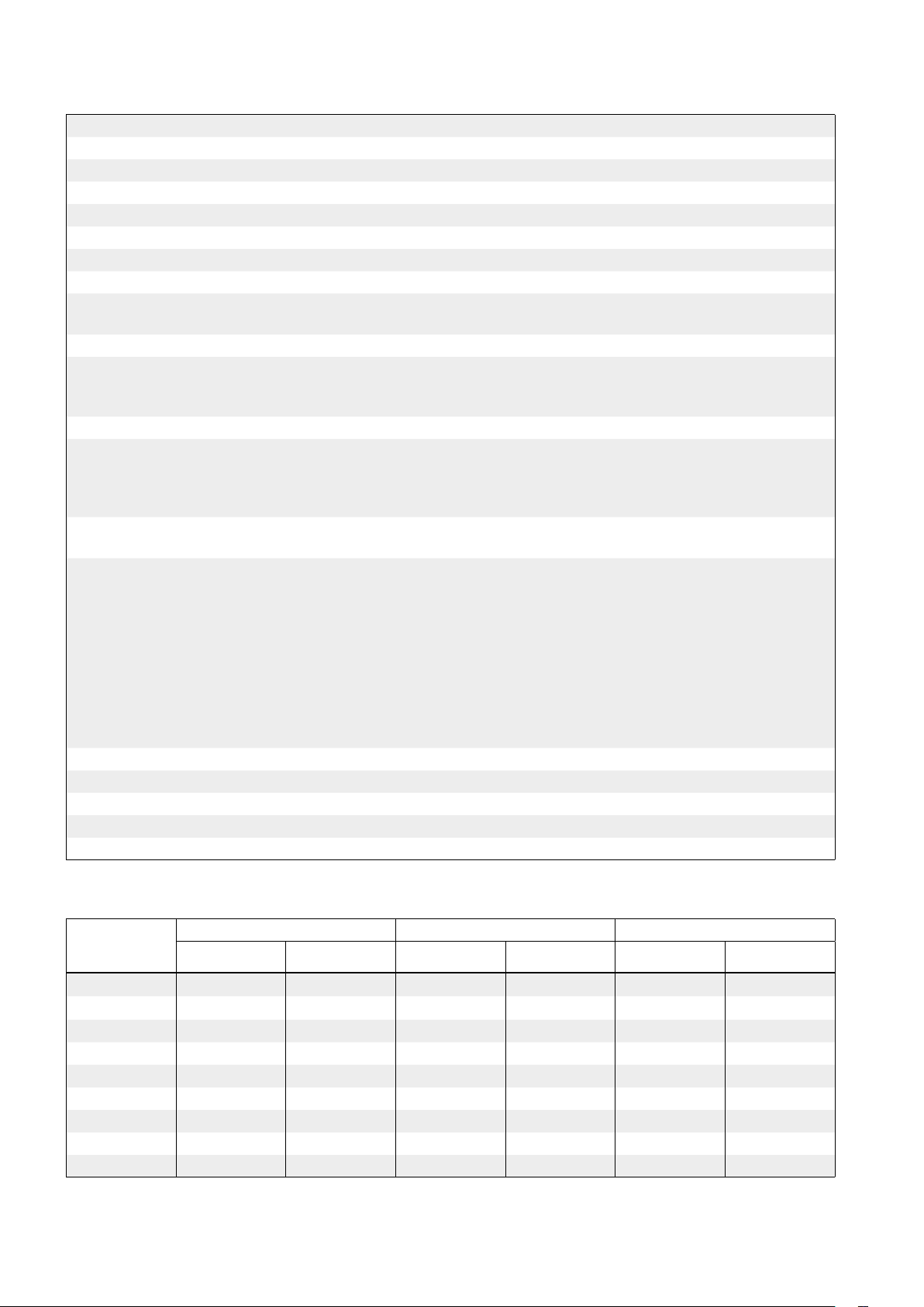
Technical data
Power supply DC 24 (18-32) V
AC 24 (24-28) V
Cable Max outer diameter 7 mm
Power consumption 0,4 W
Power consumption For wiring 0,5 VA
IP class 42
Tightness class to the environment EN 12237 D
Storage temperature range -30 to +50 °C
Maximum ambient moisture 95 %
RH
Connection RS485 standard or analog
Cable RS485 standard cable, 2-wire shiel-
ded twisted pair, min. 0,1 mm² (LIYCY
cable)
Protocol Modbus
±5
m³/h
l/s
m/s
°C
% or
l/s
l/s
l/s
l/s
l/s
l/s
l/s
l/s
l/s
Output Flow
Flow
Velocity
Temperature
Velocity range For guaranteed measurement uncer-
tainty
Measurement uncertainty, flow
(min. 5 diamters of straight duct before the UltraLink.)
Temperature range -10 to +50 °C
Measurement uncertainty temperature ±1 °C
Screws on lid of display unit TX10 4 pcs
Bluetooth signal Frequency 2402 — 2480 MHz
Depending on which is the greatest
of the percentage or the absolute
value for the specific product size.
Output power -40 to +9 dB
Dim. 100 = ±1,00
Dim. 125 = ±1,25
Dim. 160 = ±1,60
Dim. 200 = ±2,00
Dim. 250 = ±2,50
Dim. 315 = ±3,15
Dim. 400 = ±4,00
Dim. 500 = ±5,00
Dim. 630 = ±6,30
0,2 - 15,0 m/s
Airflows
0,2 m/s 7,0 m/s 15,0 m/s
Ø [mm]
100 6 2 198 55 425 118
125 9 3 309 86 662 184
160 14 4 507 141 1087 302
200 23 6 792 220 1696 471
250 35 10 1237 344 2650 736
315 56 16 196 4 546 4208 116 9
400 90 25 3167 880 6786 1885
500 141 39 4948 1374 106 03 2945
630 224 62 7855 2182 16833 4676
m³/h l/s m³/h l/s m³/h l/s
We reserve the right to make changes without prior notice
13
Page 14
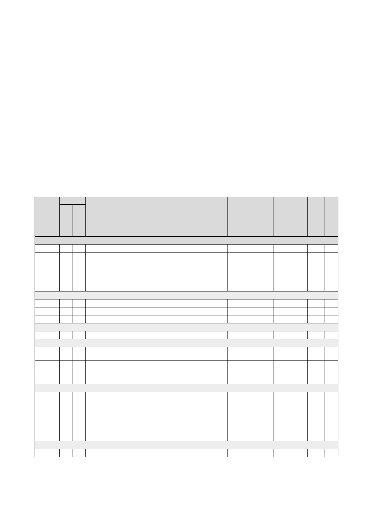
Appendix A – Modbus register
Address : Modbus register address (3x indicates Input & 4x indicates Holding)
UltraLink
®
: Type of UltraLink® where the register is available (Indicated by “x”)
Name: Name of register
Description: Short description of register.
Data type: Data type for register (16bit contained in one register, 32bit and float in two consecutive registers) .
Unit: Unit for register value (if any).
Div: Scale factor for stored value (divide register value with “div” to get correct value).
Default: Default setting.
Min: Minimum value allowed for the register.
Max: Maximum value allowed for the register.
Access: RO for read only (Input registers) and RW for read and write (Holding registers).
Controller
®
Name Description
Monitor
0 = Normal mode;
1 = Locating flow;
2 = Override control;
3 = Error;
4 = Control loop regulating;
5 = Angle sensor calibrating
open.
0 = Motor stopped.
1 = Motor opening damper
2 = Motor closing damper
1 = Motor not working.
2 = Angle sensor not working correctly.
3 = Flow setpoint not reached.
4 = Flow measure problems.
5 = Damper is regulating.
6 = Not used.
7 - 31 = Reserved for future use.
32 = Factory data is corrupted.
Data type
Unit
Div
Default
Min
Max
16bit RO
16bit % 10 RO
16bit RO
32bit RO
UltraLink
Address
INPUT REGISTERS
3x008 X X Product Nominal Size Nominal diameter of duct 16bit mm RO
3x013 X X Unit Status Current unit status:
Flow info
3x150 X X Velocity in m/s Average velocity in m/s Float m/s RO
3x152 X X Air flow in m³/h Average air flow in m³/h Float m³/h RO
3x154 X X Air flow in l/s Average air flow in l/s Float l/s RO
Temperature info
3x200 X X Current temperature in ºC Temperature in degree celcius. 16bit ºC 10 RO
Damper info
3x251 X Damper open in % Damper actual position in percentage
3x252 X Damper motor action Damper motor action:
Alarms
3x400 X X Alarm Register 1 Alarms 1-32 - bitwise:
Other
3×500 X X Signal amplification Current signal amplification 16bit 0 3 20 RO
Access
14
We reserve the right to make changes without prior notice We reserve the right to make changes without prior notice
Page 15
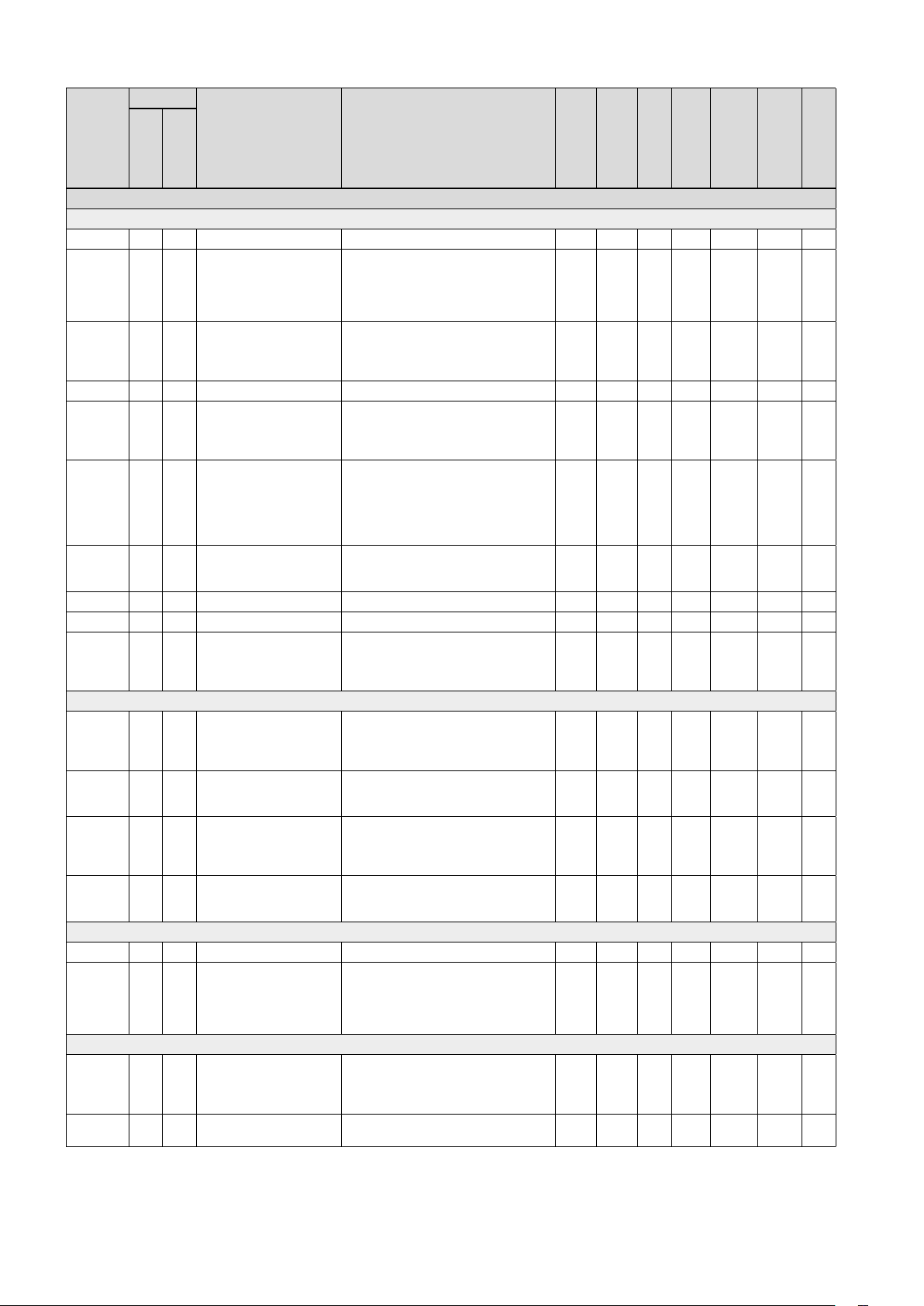
UltraLink
®
Address
HOLDING REGISTERS
Communication settings
4x001 X X Communication id Modbus address 16bit 1 239 RW
4x002 X X RS485 Baud Rate Conf. Baudrate:
4x003 X X RS485 Parity Conf. Parity:
4x004 X X RS485 Stop Bit Conf. Number of stopbits: 1 or 2. 16bit 1 1 2 RW
4x005 X X RS485 Protocol Conf. Protocol:
4×006 X X Bluetooth Password Password which must be provided to
4×007 X X Bluetooth Enable Enable Bluetooth Communication
4x008 X X PLA ID used for Pascal 16bit 1 239 RW
4x009 X X ELA ID used for Pascal 16bit 1 239 RW
4×010 X X Bluetooth TX Power Level Configure TX Power Level dBm. Accep-
System configuration
4x070 X Damper Regulation Conf. Specifies how damper is regulated:
4x071 X Damper Input Conf. Specifies input to control damper:
4x082 X X Execute Factory Reset Factory reset of all parameters. Unit will
4x083 X X Execute Reboot Reboot the unit
Override configuration
4x150 X Damper Override Timeout Time before returning to normal mode 16bit min 120 0 600 RW
4x151 X Damper Override Conf. 0 = Normal mode;
Damper
4x300 X Execute Angle Calibration 0 = Do nothing;
4x302 X Angle Set Point Angle setpoint used in normal mode.
Controller
Name Description
Monitor
0 = 9600
1 = 19200
2 = 38400
3 = 76800
0 = Odd;
1 = Even;
2 = None
0 = Modbus;
1 = Not used;
2 = Pascal;
pair Bluetooth devices. This password
can always be changed from wired
connection. From wireless it can only be
changed when connection is established
using current password.
0 = Bluetooth turned off;
1 = Bluetooth turned on;
ted values:
-40, -20, -16, -12, -8, -4, 0, 2, 3, 4, 5, 6,
7, 8, 9
0 = Regulator turned off
1 = Regulate damper angle
2 = Regulate flow
0 = Modbus or Pascal
1 = Analog input
restart
0 = Do nothing;
1 = Factory Reset
0 = Do nothing;
1 = Reboot the unit;
1 = Override control - Max open;
2 = Override control - Min open;
3 = Override control - 100% open;
4 = Override control - 100% closed
1 = Start recalibration of the angle
sensor;
2 = Start recalibration when starting up;
(Only relevant when 4x070 is set to 1 )
Data type
Unit
Div
Default
Min
Max
16bit 1 0 3 RW
16bit 0 0 2 RW
16bit 0 0 2 RW
16bit 1111 0000 9999 RW
16bit 1 0 2 RW
16bit 0 -40 9 RW
16bit 2 0 2 RW
16bit 1 0 1 RW
16bit 0 0 1 RW
16bit 0 0 1 RW
16bit 0 0 4 RW
16bit 0 0 2 RW
16bit % 0 0 100 RW
Access
* = the value depends on the dimension of the product.
We reserve the right to make changes without prior notice
15
Page 16
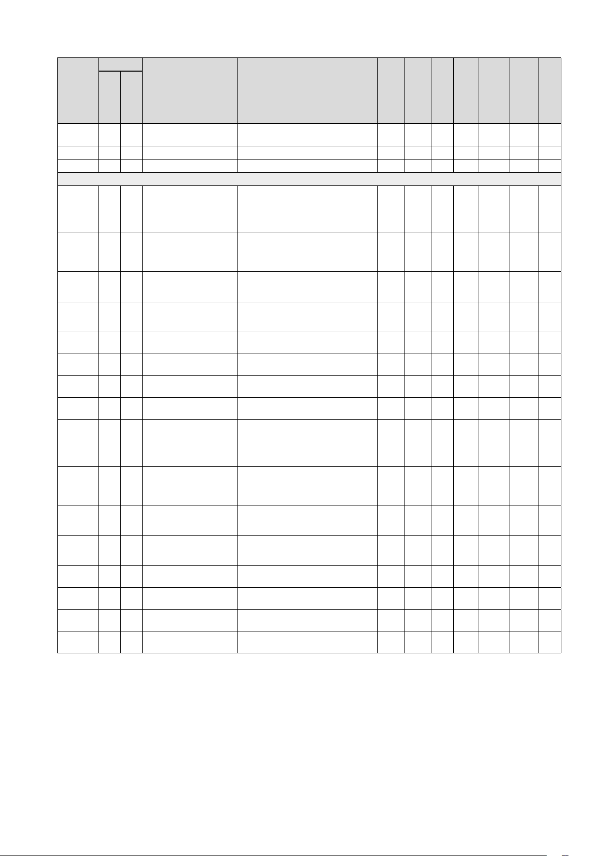
UltraLink
®
Address
4x314 X Flow Set Point Flow setpoint used in normal mode.
4x315 X Flow Set Point Minimum Flow setpoint min. 16bit l/s * 0 4700 RW
4x316 X Flow Set Point Maximum Flow setpoint max. 16bit l/s * 0 4700 RW
Analog output
4x400 X X Analog Output 1 Level
4x401 X X Analog Output 1 Unit Conf. Show:
4x402 X X Analog Output 1 Temp.
4x403 X X Analog Output 1 Temp.
4x404 X X Analog Output 1 Flow Min. Min flow shown = Min output voltage
4x406 X X Analog Output 1 Flow Max. Max flow shown = Max output voltage
4x408 X Analog Output 1 % Open
4x409 X Analog Output 1 % Open
4x430 X X Analog Output 2 Level
4x431 X X Analog Output 2 Unit Conf. Show:
4x432 X X Analog Output 2 Temp.
4x433 X X Analog Output 2 Temp.
4x434 X X Analog Output 2 Flow Min. Min flow shown = Min output voltage
4x436 X X Analog Output 2 Flow Max. Max flow shown = Max output voltage
4x438 X Analog Output 2 % Open
4x439 X Analog Output 2 % Open
Controller
Name Description
Monitor
(Only relevant when 4x070 is set to 2 )
Conf.
Min.
Max.
Min.
Max.
Conf.
Min.
Max.
Min.
Max.
Analog output config:
0 = 0-10V,
1 = 10-0V,
2 = 2-10V,
3 = 10-2V.
0 = Flow;
1 = Temperature;
2 = Angle;
Min temperature shown = Min output
voltage (Only relevant when 4x401 is set
to 1 )
Max temperature shown = Max output
voltage (Only relevant when 4x401 is set
to 1 )
(Only relevant when 4x401 is set to 0 )
(Only relevant when 4x401 is set to 0 )
Min open % shown = Min output voltage
(Only relevant when 4x401 is set to 2 )
Max open % shown = Max output voltage (Only relevant when 4x401 is set to 2 )
Analog output config:
0 = 0-10V,
1 = 10-0V,
2 = 2-10V,
3 = 10-2V.
0 = Flow
1 = Temperature
2 = Angle
Min temperature shown = Min output
voltage (Only relevat when 4x431 is set
to 1 )
Max temperature shown = Max output
voltage (Only relevant when 4x431 is set
to 1 )
(Only relevant when 4x431 is set to 0 )
(Only relevant when 4x431 is set to 0 )
Min open % shown = Min output voltage
Only relevant when 4x431 is set to 2 )
Max open % shown = Max output voltage (Only relevant when 4x431 is set to 2 )
Data type
Unit
Div
Default
Min
Max
16bit l/s * 0 4700 RW
16bit 2 0 3 RW
16bit 0 0 2 RW
16bit ºC 0 -40 50 RW
16bit ºC 50 -40 50 RW
16bit l/s 0 -4700 4700 RW
16bit l/s * -4700 4700 RW
16bit % 10 0 0 1000 RW
16bit % 10 1000 0 1000 RW
16bit 2 0 3 RW
16bit 2 0 2 RW
16bit ºC 0 -40 50 RW
16bit ºC 50 -40 50 RW
16bit l/s 0 -4700 4700 RW
16bit l/s * -4700 4700 RW
16bit % 10 0 0 1000 RW
16bit % 10 1000 0 1000 RW
Access
* = the value depends on the dimension of the product.
16
We reserve the right to make changes without prior notice We reserve the right to make changes without prior notice
Page 17
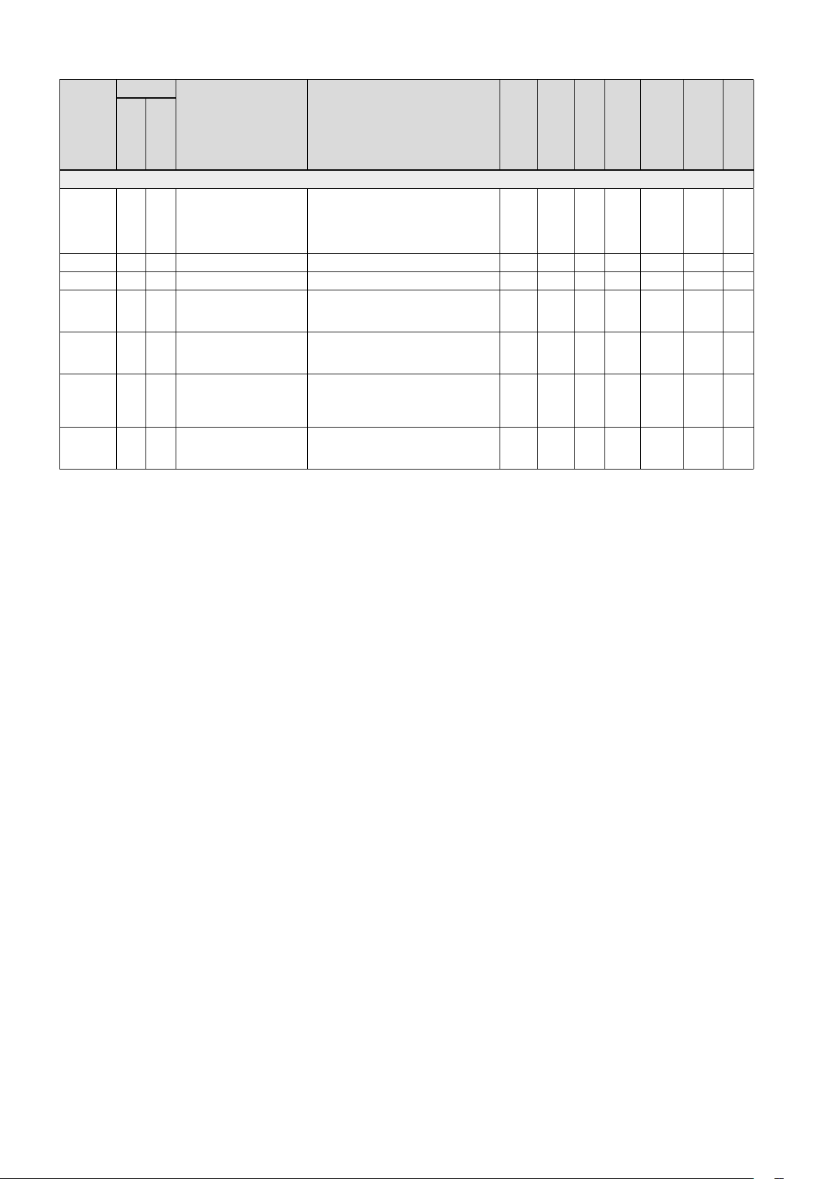
UltraLink
®
Address
Analog input (Settings below are only relevant when register 4x071 is set to 1)
4x500 X Analog In Level Conf. Analog input:
4x501 X Analog In Angle Minimum Min angle = min voltage 16bit % 0 0 100 RW
4x502 X Analog In Angle Maximum Max = max voltage 16bit % 100 0 100 RW
4x503 X Analog In Flow Minimum Min flow = min voltage
4x504 X Analog In Flow Maximum Max flow = max voltage
4x510 X Analog In Override Low
4x511 X Analog In Override Low
Controller
Name Description
Monitor
0 = 0-10V,
1 = 10-0V,
2 = 2-10V,
3 = 10-2V.
(Must be equal or higher than register
4x315)
(Must be equal or lower than register
4x316)
Trigger Min.
Trigger Max.
Lowest voltage level to activate 1st
Override level
(Only relevant when 4x500 is set to 2
or 3)
Highest voltage level to activate 1st
Override level (Only
relevant when 4x500 is set to 2 or 3)
Data type
Unit
Div
Default
Min
Max
16bit 2 0 3 RW
16bit l/s 0 0 4700 RW
16bit l/s * 0 4700 RW
16bit V 10 0 0 20 RW
16bit V 10 8 0 20 RW
Access
* = the value depends on the dimension of the product.
We reserve the right to make changes without prior notice
17
Page 18

At Lindab, good thinking is a philosophy that gui-
des us in everything we do. We have made it our
mission to create a healthy indoor climate – and
to simplify the construction of sustainable buil-
dings. We do that by designing innovative pro-
ducts and solutions that are easy to use, as well
as offering efficient availability and logistics. We
are also working on ways to reduce our impact on
our environment and climate. We do that by de-
veloping methods to produce our solutions using
a minimum of energy and natural resources, and
by reducing negative effects on the environment.
We use steel in our products. It’s one of few materi-
als that can be recycled an infinite number of times
without losing any of its properties. That means
less carbon emissions in nature and less energy
wasted.
We simplify construction
2019 -10-10
www.lindab.com
 Loading...