

Lincoln Manufacturing 1960 Series Operation Manual
operator manual
Dual Technology Finisher
This document includes:
• Safety Notices
• Specifications
• Installation Instructions
• Operating Instructions
• Cleaning Instructions
• Warranty Statement
Revision: F
P/N: 2810322
Series 1960
Lincoln Foodservice Products, LLC
1111 North Hadley Road
Fort Wayne, Indiana 46804
United States of America
Technical Support Hotline: (800) 678-9511
Telephone: (260) 459-8200
www.lincolnfp.com
IMPORTANT WARNING AND SAFETY INFORMATION
WARNING:
!
DANGER!
!
DANGER!
!
DANGER!
!
DANGER!
!
DANGER!
!
This manual contains important safety and installation-operation instructions. Require all operators to
read this manual thoroughly before installing, operating or servicing this equipment. Improper
installation, adjustment, alteration, service or maintenance can cause property damage, injury or
death.
Do not work around conveyor belt with long hair, loose clothing, or dangling jewelry. Getting caught in the
belt could result in serious injury.
For your safety, do not store or use gasoline or other flammable vapors or liquids in the vicinity of this or
any other appliance.
Do not spray aerosols in the vicinity of this appliance while it is in operation.
If the power supply cord appears to be damaged, do not attempt to operate the unit. Contact a service
agent or qualified electrician to repair!
Do not use parchment paper when placing food product through the appliance! Use of such materials
may cause a fire and should never be placed in the appliance.
• Minimum clearances must be maintained from all walls and combustible materia ls.
• Keep the appliance area free and clear of combustible material.
• Adequate clearance for air openings to the control chamber on both sides of the appliance is required.
• Do not obstruct the ventilation holes in the control boxes and covers as these provide cooling air for the controls.
• The appliance is to be operated only on the type of electricity as shown on the specification plate.
• This manual should be retained for future reference.
• The electrical wiring diagram is located under the control box cover.
• The fixed supply wiring insulation must be protected against high interior surface temperatures.
BEFORE INSTALLATION
Upon receipt of this unit, immediately unpack and remove any protective packaging to inspect for possible
concealed shipping damage. If unit is found to be damaged, save all packing materials and contact your delivery
carrier within 5 days. If there is apparent damage:
United States and Canada: Arrangements should be made to file a claim against the carrier as Interstate
Commerce Regulations require that the claim must be initiated by the consignee.
Other Countries
Proper and secure storage facilities should be arranged for the unit(s), if necessary, to protect against outdoor or
damp conditions at all times before installation. Failure to follow these instructions will negate Lincoln Foodservice
Product’s or your ability to file claims and receive compensation for shipping damage.
: Freight terms will be developed and extended on an individual basis.
DTF – 1960 Series Operator Manual
2
PURCHASER’S RESPONSIBILITY
It is the responsibility of the purchaser to:
1. See that the electric service for the unit is installed on site in accordance with the manufacturer’s
specification.
2. Unload, uncrate and install the unit in its proper location in accordance with this installation/operation
manual.
3. See that the unit is placed on an oven stand for operation. Any surface other than an oven stand is
unacceptable.
4. See that the electric service is connected properly by a qualified installer of your choice. All such
connections must be in accordance with applicable code requirements. Refer to “Code References”
section for more information.
5. The fixed supply wiring insulation must be protected against high interior surface temperatures.
!
!
CAUTION:
WARNING:
Do not install the unit(s) in any area with an ambient temperature in excess of 95°F /
35°C. Doing so will cause damage to the unit(s).
This equipment is not to be used by children or infirmed persons.
TABLE OF CONTENTS
IMPORTANT WARNING & SAFETY INFORMATION.......................................….............. 2
BEFORE INSTALLATION…………..................................................................................... 2
PURCHASER’S RESPONSIBILITY.................................................................................... 3
EXTERIOR DIMENSIONS……..…….................................................................................. 4
UTILITY SPECIFICATION.................................................................................................. 4
INSTALLATION & STACKING INSTRUCTIONS................................................................ 5
ELECTRICAL GROUNDING INSTRUCTIONS..................................................…............. 6
SPACING…………………………………………………….................................................... 6
VENTILATION..................................................................................................................... 6
PROGRAMMING & OPERATING INSTRUCTIONS........................................................... 7
CLEANING INSTRUCTIONS & OPERATOR MAINTENANCE.......................................... 10
PREVENTIVE MAINTENANCE.......................................................................................... 14
HOW TO OBTAIN SERVICE.............................................................................................. 14
LABEL DEFINITIONS………............................................................................................... 15
WARRANTY……………………........................................................................................... 17
DTF – 1960 Series Operator Manual
3
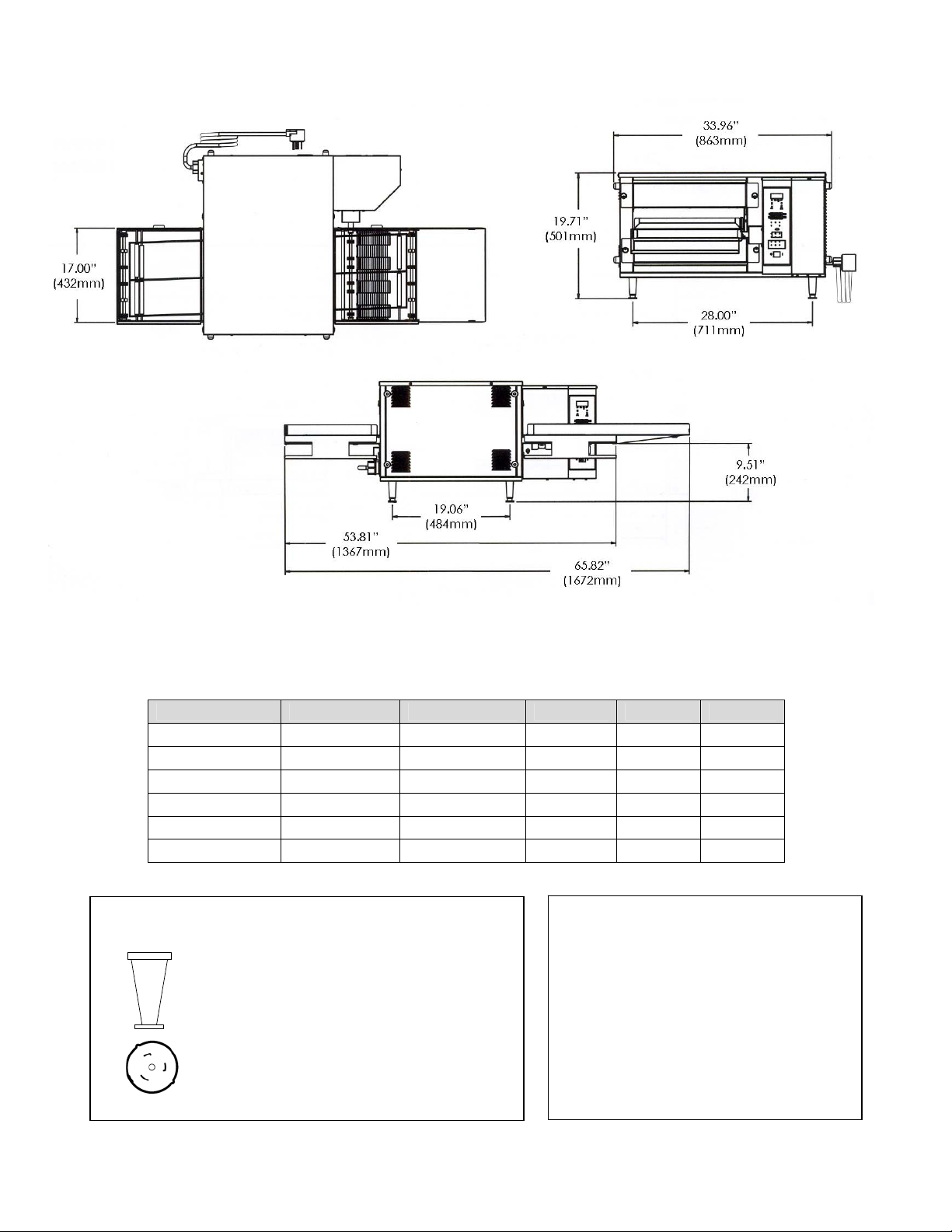
EXTERIOR DIMENSIONS
UTILITY SPECIFICATION
Model # Input Rate Voltage Amps Phase HZ
1961 12 kW 208V 36 3 60
1962 12 kW 240V 32 3 60
1962-000-E 11.5kW 415/240V 34.5 3 50
1963-000-E 11.5kW 400/230V 36 3 50
1964-000-E 11.5kW 380/220V 37.5 3 50
1964 11.5kW 220V 37.5 3 50
COMPONENTS
4” LEG
ANGLE PLUG – 50 AMP, 250 VAC, 3 PHASE
(Domestic units only)
(Wire & Plug not included with CE units)
DTF – 1960 Series Operator Manual
4
REQUIRED CLEARANCE
The unit must have 6 inches (152 mm) of
clearance from combustible surfaces. In case
other equipment is located on the right side of
the unit, a minimum clearance of 24 inches
(610 mm) is required from that equipment.
FOR ALL UNITS: A 24-inch (610-mm)
clearance at the rear of the unit must be
obtainable for service access.
INSTALLATION & STACKING INSTRUCTIONS (if applicable)
Other than the optional legs, this unit is ready for operation after uncrating. In the event that you ordered a “doublestack” of two Dual Technology Finishers, stacking brackets will be required to properly anchor the equipment
together. When stacking appliances, it is required that two stacking brackets be properly attached to the units to
ensure a proper fit and connection.
!
WARNING:
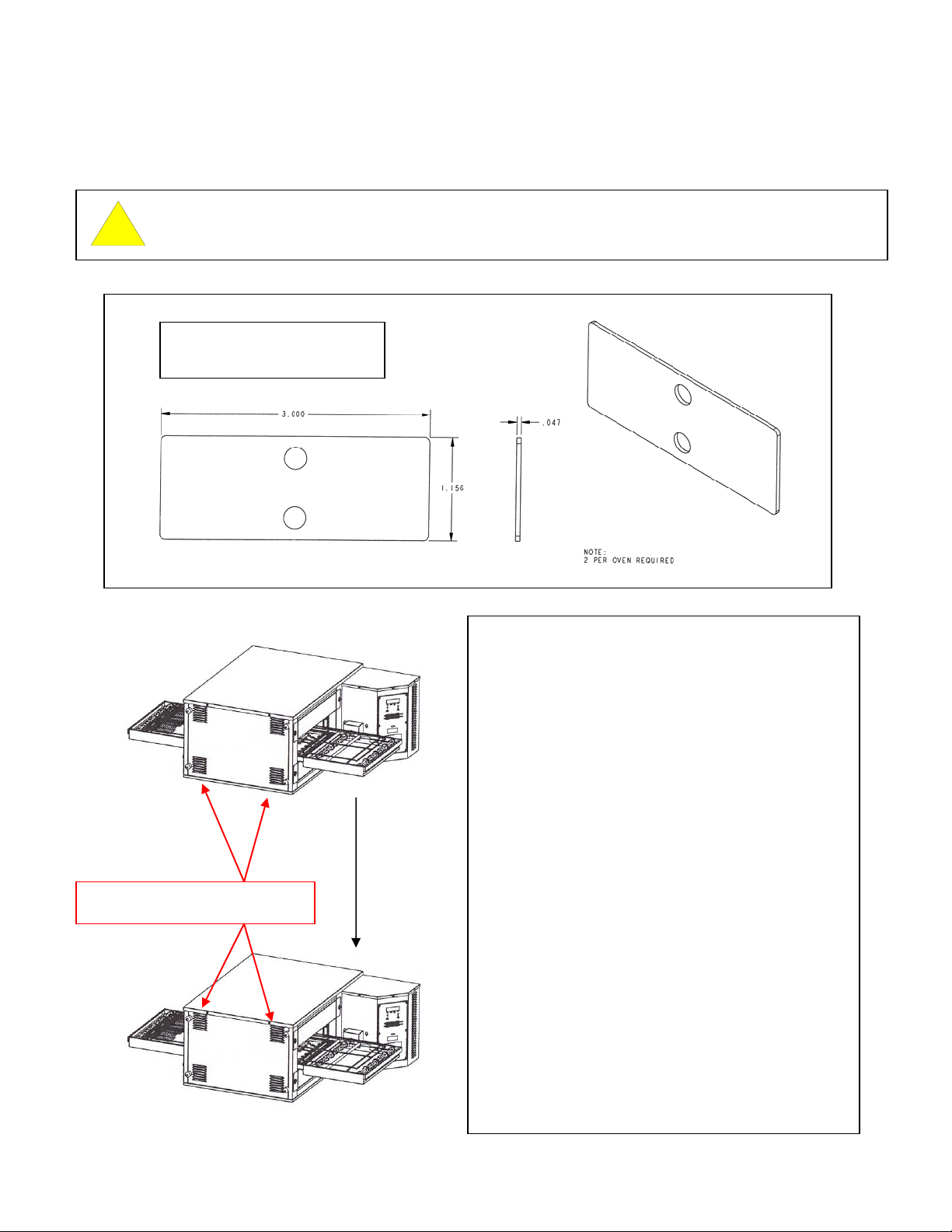
DTF STACKING BRACKET
Part Number: 7008811
Two stacking brackets must be used when stacking two DTF units together. A
maximum of two units may be stacked together.
Location of Stacking Brackets (shown
on front of oven in this case).
Stacking Brackets have been designed to align with
the screw openings for the DTF covers (upper and
lower). Two brackets are required for each set of
appliances and may be placed either on the front or
back of the appliances.
Utilize the following instructions to properly stack the
DTF units together.
1. Turn each unit off and unplug each unit from its
power source.
2. Remove the two screws from the “Unit Top” of the
bottom appliance.
3. Remove the legs from the top appliance. Remove
the two screws from the “Unit Bottom” of the top
appliance.
4. Gently lower the top unit onto the bottom unit
making sure to align the screw holes of the “Unit
Top” and “Unit Bottom.”
5. Once the appliances have been aligned, align the
holes in the Stacking Bracket to the holes in the
top and bottom DTF appliances. Reinsert the
screws so that the Stacking Bracket connects the
top and bottom units together. Repeat this step
with the second Stacking Bracket. The DTF units
are now properly stacked.
6. Plug each unit into its appropriate power source
and turn on to begin operation.
DTF – 1960 Series Operator Manual
5
ELECTRICAL GROUNDING INSTRUCTIONS
!
WARNING:
!
WARNING
INT’L (CE):
!
WARNING
DOMESTIC:
If the supply cord appears to be damaged, do not attempt to operate unit. Contact
service agent or qualified technician to repair.
This appliance must be properly grounded at time of installation. Failure to ensure
that this equipment is properly grounded can result in electrocution, dismemberment
or fatal injury.
As it pertains to domestic models, this appliance is equipped with a three-prong
(grounding) plug for your protection against shock hazard and should be plugged
directly into a properly grounded three-prong receptacle. Do not cut or remove the
grounding prong from this plug.
ELECTRICAL CODE REFERENCE
IN USA
When installed, this appliance must be electrically grounded and its installation must comply with the National
Electric Code, ANSI-NFPA 70, latest edition, the Manufacturer’s Installation Instructions, and applicable municipal
building codes.
IN CANADA
All electrical connections are to be made in accordance with CSA C22.1 – Canadian Electrical Code Part 1 and/or
local codes.
ALL OTHER COUTRIES
Local electrical codes will prevail.
1. Strain Relief is provided with each unit. International Dealer/Distributor provides applicable power cord/plug for
each customer.
2. All pole disconnection switch 3mm open contact distance.
3. To prevent electrical shock, an equal potential bonding ground-lug is provided in the back. This allows the
appliance to be connected to an external bonding system.
4. When used as a double-stack (if applicable) and each appliance has its own disconnection switch, all switches
should be closed together.
SPACING
The unit must have 6 inches (152mm) of clearance from combustible surfaces. In case other equipment is located
on the right side of the unit, a minimum clearance of 24 inches (610mm) is required from that equipment.
Additionally, a 24 inch (610mm) clearance at the rear of the unit must be obtainable for service access.
VENTILATION
Ventilation is not required but local codes prevail. These are the “authority having jurisdiction” as stated by the
NATIONAL FIRE PROTECTION ASSOCIATION, INC. in NFPA 96, latest edition.
DTF – 1960 Series Operator Manual
6
 Loading...