

Page 1
®
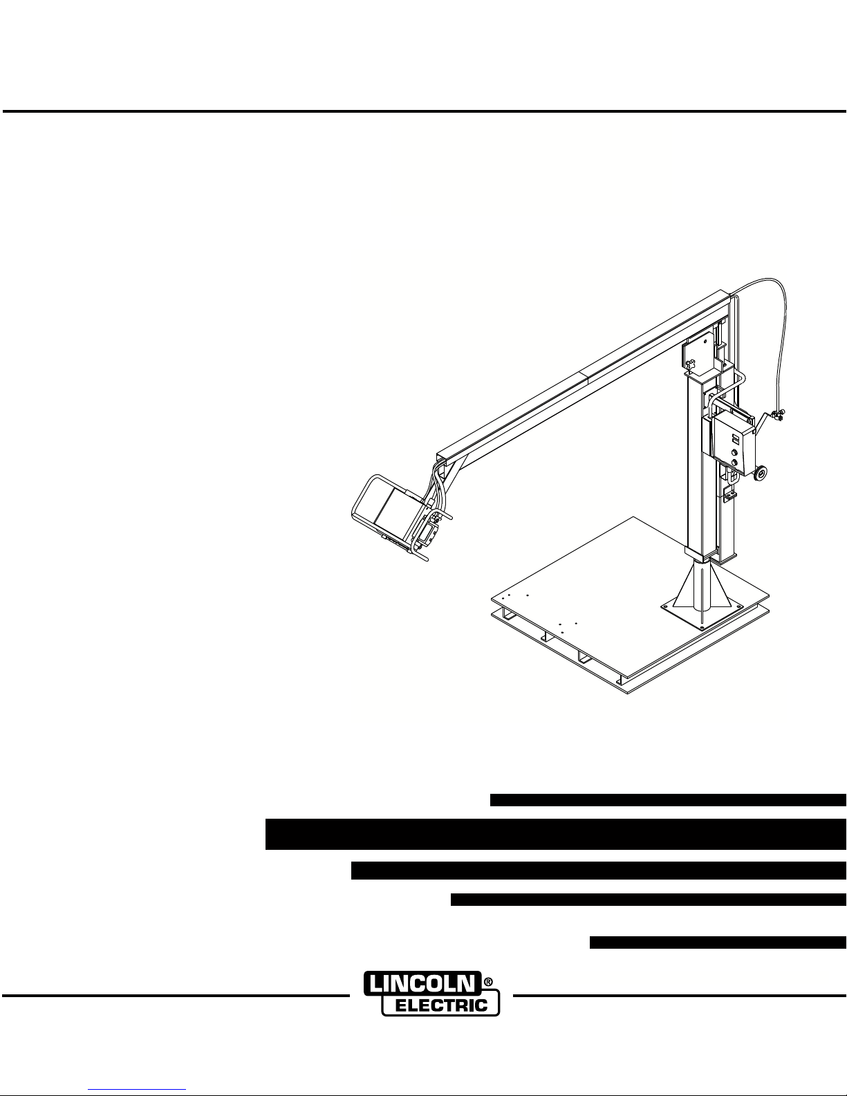
LN-10 / ZIPLINE BOOM PACKAGE
IM596-2A
March, 2001
For use with “K” Sales Spec Numbers:
Safety Depends on You
Lincoln arc welding and cutting
equipment is designed and built
with safety in mind. However, your
overall safety can be increased by
proper installation ... and thoughtful operation on your part. DO
NOT INSTALL, OPERATE OR
REPAIR THIS EQUIPMENT
WITHOUT READING THIS
MANUAL AND THE SAFETY
PRECAUTIONS CONTAINED
THROUGHOUT. And, most
importantly, think before you act
and be careful.
K1564-2
K1564-3
K1564-5
OPERATOR’S MANUAL
• Sales and Service through Subsidiaries and Distributors Worldwide •
Cleveland, Ohio 44117-1199 U.S.A. TEL: 216.481.8100 FAX: 216.486.1751 WEB SITE: www.lincolnelectric.com
Copyright © 2001 Lincoln Global Inc.
• World's Leader in Welding and Cutting Products •
Page 2

i
SAFETY
WARNING
READ AND FOLLOW ALL WARNING INFORMATION IN THIS AND ALL OTHER MANUALS
WARNING
SPRING UNDER PRESSURE
Release of spring pressure can cause serious personal injury and equipment
damage.
• Do not remove spring rod shipping support until boom is completely assembled
and all components are installed.
• Do not service or adjust spring pressure on boom without the spring rod shipping
support securely installed.
WARNING
MOVING BOOM PARTS CAN CAUSE SERIOUS PERSONAL INJURY.
i
• Keep hands away from spring rod clevis and swivel plates.
WARNING
FALLING BOOM CAN CAUSE SERIOUS PERSONAL INJURY AND EQUIPMENT
DAMAGE.
• Securely attach pallet base or pedestal to floor before operating boom arm.
WARNING
UNBALANCED BOOM CAN CAUSE SERIOUS PERSONAL INJURY AND
EQUIPMENT DAMAGE.
• Do not remove wire drive unit without the spring rod shipping support securely
installed.
CAUTION
ONLY QUALIFIED PERSONNEL SHOULD INSTALL, USE OR SERVICE THIS
EQUIPMENT.
READ AND FOLLOW THE MANUFACTURER’S INSTRUCTIONS AND YOUR
EMPLOYER’S SAFETY PRACTICES.
Page 3

for selecting a QUALITY product by Lincoln Electric. We want you
Thank You
to take pride in operating this Lincoln Electric Company product
••• as much pride as we have in bringing this product to you!
Please Examine Carton and Equipment For Damage Immediately
When this equipment is shipped, title passes to the purchaser upon receipt by the carrier. Consequently, Claims
for material damaged in shipment must be made by the purchaser against the transportation company at the
time the shipment is received.
Please record your equipment identification information below for future reference. This information can be
found on your sales information.
Model Name and Sales SpecNumber (K-xxx) _____________________________________
Date of Purchase __________________________________
Whenever you request replacement parts for or information on this equipment always supply the information
you have recorded above.
iiii
Read this Operators Manual completely before attempting to use this equipment. Save this manual and keep it
handy for quick reference. Pay particular attention to the safety instructions we have provided for your protection.
The level of seriousness to be applied to each is explained below:
WARNING
This statement appears where the information must be followed exactly to avoid serious personal injury or
loss of life.
CAUTION
This statement appears where the information must be followed to avoid minor personal injury or damage to
this equipment.
Page 4

iii
TABLE OF CONTENTS
Page
Installation.......................................................................................................................Section A
Product Description ..............................................................................................................A-1
Zipline Boom Models............................................................................................................A-1
Recommended Wire Feeder - Power Source Combinations ...............................................A-2
Product Specifications..........................................................................................................A-2
Unpacking and Checking Kit Contents.................................................................................A-3
Installation Procedure...........................................................................................................A-7
Tools Required..............................................................................................................A-7
Install the Wire Drive Assembly ....................................................................................A-7
Install the Control Box Assembly .................................................................................A-7
Install the Power Input Cable Assembly........................................................................A-7
Install the Electrode Weld Cable ...................................................................................A-7
Install the Control Cable Assembly ...............................................................................A-7
Install the Gas Hose......................................................................................................A-7
Install the Conduit Bushings and Electrode Conduit .....................................................A-8
Install the 2” Spindle Assembly .....................................................................................A-8
Install the Gun Control Plug Cable Assembly and the Gun and Cable Assembly ........A-8
Install the Welding Power Source .................................................................................A-8
Install the Wire Reel, Drive Rolls and Guides ...............................................................A-8
Dimension Prints ............................................................................................................Section B
12 Ft. Spring Balanced Zipline Boom Assembly ..................................................................B-1
12 Ft. Hydraulic Zipline Boom Assembly..............................................................................B-2
16 Ft. Spring Balanced Zipline Boom Assembly ..................................................................B-3
16 Ft. Hydraulic Zipline Boom Assembly..............................................................................B-4
Control Box Assembly ..........................................................................................................B-5
Wire Drive Assembly ............................................................................................................B-6
iii
Page 5
A-1
INSTALLATION
A-1
PRODUCT DESCRIPTION
This wire feeder boom package comprised of Lincoln
equipment will allow you to setup a boom welding system when used in conjunction with Zipline® boom
products. This boom package includes everything you
need from Lincoln to easily setup a standard 12 or 16
foot welding station using the Zipline boom product
line.
You will need to purchase the boom and related products from Bird Machine and Repair, Inc., 100 Station
St., Johnstown, PA. 15905, (814)288-3641, the manufacturer of the Zipline® boom product line.
The Lincoln boom package will include the following
items:
Wire Drive Assembly
Control Box Assembly
Electrode Weld Cables
Control or Linc-Net Cables
Gas Hoses
Electrode Conduits
2" Spindle Assemblies
Hardware Kit
Conduit Bushing Kit
Gun Control Plug Cable Assembly (1 per Head)
Wire Feeder Instruction Manual
Boom Package Instruction Manual
ZIPLINE BOOM MODELS
Both 12 and 16 foot boom length models are available
from Zipline. Two different boom balancing designs
are also available; a spring balanced boom model and
a hydraulic boom model. The standard Zipline boom
configurations are as follows:
12' Spring Balanced Zipline Boom
16' Spring Balanced Zipline Boom
12' Hydraulic Zipline Boom
16' Hydraulic Zipline Boom
The following items will be provided by Bird Machine and Repair
Inc., the manufacturer of the Zipline boom product line:
Pallet Base Assembly (optional)
Pedestal Base Assembly
Boom Mast
Spring Retainer Housing or Hydraulic Device
Boom Arm
Cable and Hose Trough
Conduit Bushing Bracket
Provisions to Mount 2" Spindle Assembly
Control Box Support Assembly (optional)
Feeder Mount Bracket and Cage Assembly (optional)
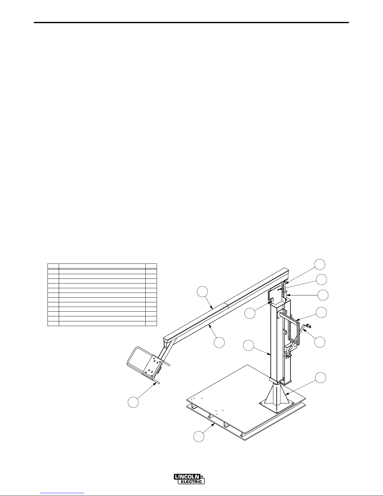
See Figure A.1 for illustration of the Zipline products.
See the following pages for illustrations of the Lincoln
Products.
DESCRIPTIONITEM
12PALLET BASE ASSEMBLY (OPTIONAL)
PEDESTAL ASSEMBLY
BOOM MAST & SPRING RETAINER HOUSING ASSY
3
4
SPRING ROD CLEVIS
5
MAIN SWIVEL PIN
6
FRICTION CONTROL KNOB
7
SPRING ROD SHIPPING SUPPORT
CONDUIT BUSHING BRACKET
8
9
CONTROL BOX SUPPORT ASSEMBLY (OPTIONAL)
10
BOOM ARM ASSEMBLY
11
CABLE & HOSE TROUGH
FEEDER MOUNT BRACKET & CAGE ASSEMBLY (OPTIONAL)
12
12
QTY.
4
1
1
1
1
1
1
1
2
1
1
2
1
11
6
10
1
3
ZIPLINE BOOM PACKAGES
8
S
5
7
9
2
24078
24078
A
FIGURE A.1
LN-10 / ZIPLINE BOOM PACKAGE
Page 6

A-2
INSTALLATION
A-2
RECOMMENDED WIRE FEEDER POWER SOURCE COMBINATIONS
The Zipline booms have been designed to integrate
with newer wire feeders and power sources. The following is a list of wire feeders and power sources that
are compatible with the Zipline boom’s pallet base,
control box support and feeder mount bracket/cage
assembly.
Wire Feeders Power Sources
LN-10 CV-250
DH-10 CV-300-I
CV-300
CV-400-I
CV-400
CV-500-I
CV-655
** DC-250
DC-400
** PP-500
** DC-600
DC-655
** DC-1000
See the appropriate Dimension Print in Section B of
this manual for details on the physical size of the
equipment.
PF-10 PW-455
STT-10 STT-II
** A K1520-1 115V/42V Transformer Kit is required
with these power sources.
PRODUCT SPECIFICATIONS
Product Number Product Description Net Weight (lbs.)
K1564-2 LN-10 Boom Package - 90
12' Zipline Boom
K1564-3 LN-10 Boom Package - 103
16' Zipline Boom
K1564-5 LN-10 Boom Package - 90
12' Zipline Boom
LN-10 / ZIPLINE BOOM PACKAGE
Page 7
A-3
REQUIRED TOOLS
UNPACK THE BOOM PACKAGE
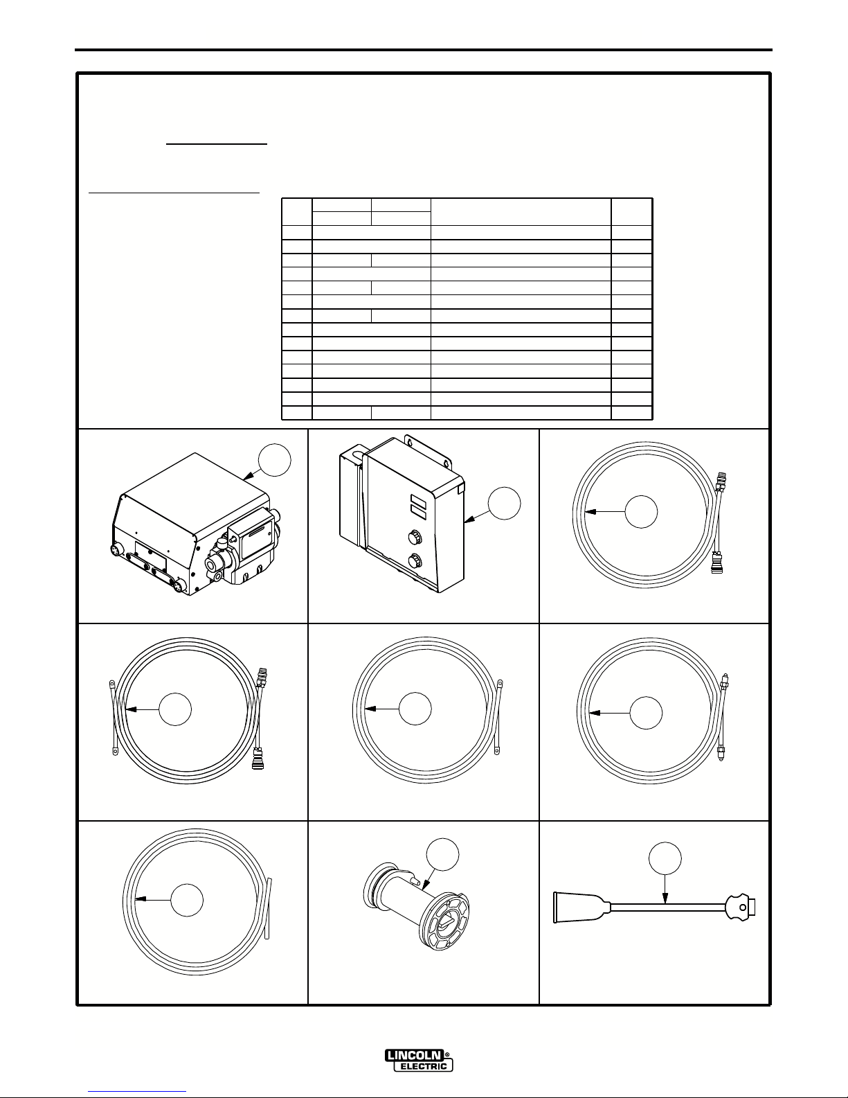
CHECK YOUR BOOM PACKAGE
FOR THE FOLLOWING:
INSTALLATION
K1564-2 LN-10 B00M PACKAGE - 12' ZIPLINE BOOM
K1564-3 LN-10 B00M PACKAGE - 16' ZIPLINE BOOM
ITEM
1
2
L9776-C-18 L9776-C-22
3
4
5
6
7
8
9
10
11
12
13
INSTRUCTION MANUAL
11/16" WRENCH7/16" WRENCH 3/4" WRENCH
1/2" WRENCH
K1564-3K1564-2
PART NO.PART NO.
M18899-1
M17869-5
M18298-2-10
CL012325
CL012326
S18453-3
S20023-A-21S20023-A-17
M14935-1
S23858-2
S23859
M15608
L3326-169
L2213-528
FLAT HEAD SCREWDRIVERPHILLIPS HEAD SCREWDRIVER
DESCRIPTION
WIRE DRIVE ASSEMBLY
CONTROL BOX ASSEMBLY
CONTROL CABLE ASSEMBLY
POWER INPUT CABLE ASSEMBLY
ELECTRODE WELD CABLE
GAS HOSE
ELECTRODE CONDUIT
2" SPINDLE ASSEMBLY
HARDWARE KIT
CONDUIT BUSHING KIT
GUN CONTROL ASSEMBLY
BOOM PACKAGE INSTRUCTION MANUAL
WIRE FEEDER INSTRUCTION MANUAL
A-3
REQ'D
1
1
1
1
1
1
1
1
1
1
1
1
1
1
(1) WIRE DRIVE ASSEMBLY
4
(1) POWER INPUT CABLE ASSEMBLY
2
(1) CONTROL BOX ASSEMBLY
5
(1) ELECTRODE WELD CABLE
8
3
(1) CONTROL CABLE ASSEMBLY
6
(1) GAS HOSE
11
7
(1) ELECTRODE CONDUIT
(1) 2" SPINDLE ASSEMBLY
LN-10 / ZIPLINE BOOM PACKAGE
(1) GUN CONTROL ASSEMBLY
Page 8
A-4
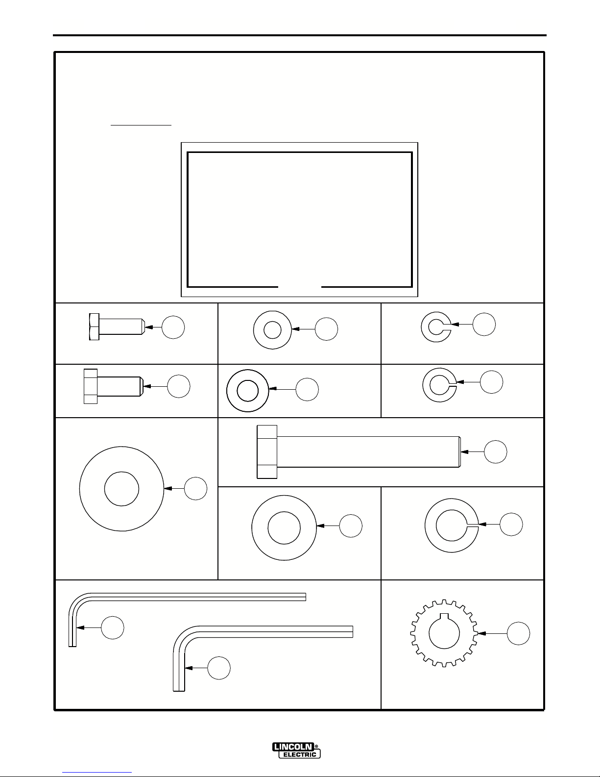
ITEM 9 S23858-2
INSTALLATION
K1564-2 LN-10 B00M PACKAGE - 12' ZIPLINE BOOM
K1564-3 LN-10 B00M PACKAGE - 16' ZIPLINE BOOM
INSTRUCTION MANUAL
A-4
1
(3) 1/4-20X.75 HHCS-GR2
4
(4) 5/16-18X.75 HHCS-GR2
ITEM
PART No.
CF000014
1
2
S9262-98
3
E106A-2
CF000040
4
5
S9262-30
6
E106A-14
S9262-14
7
8 T8833-64
9
S9262-1
10 E106A-15
11 T11563-2
12 T11563-3
M18223-113
HARDWARE KIT
DESCRIPTION
1/4-20X.75 HHCS-GR2
PLAIN WASHER
LOCKWASHER
5/16-18X.75HHCS-GR2
PLAIN WASHER
LOCKWASHER
PLAIN WASHER
1/2-13X3.00HHCS-GR8
PLAIN WASHER
LOCKWASHER
1/8 ALLEN WRENCH
3/16 ALLEN WRENCH
LOW SPEED PINION
2
(3) PLAIN WASHER
5
(4) PLAIN WASHER
QTY.
3
3
3
4
4
4
1
1
1
1
1
1
1
B-RW
S23858-2
(3) LOCK WASHER
(4) LOCK WASHER
3
6
(1) PLAIN WASHER
(1) SOCKET KEY-1/8 ALLEN WRENCH
11
(1) 1/2-13X3.0 HHCS-GR8
7
9
(1) PLAIN WASHER
(1) SOCKET KEY-3/16 ALLEN WRENCH
12
LN-10 / ZIPLINE BOOM PACKAGE
8
10
(1) LOCK WASHER
13
(1) LOW SPEED PINION
Page 9

A-5
ITEM 10 S23859
INSTALLATION
K1564-2 LN-10 B00M PACKAGE - 12' ZIPLINE BOOM
K1564-3 LN-10 B00M PACKAGE - 16' ZIPLINE BOOM
INSTRUCTION MANUAL
A-5
PART No.
ITEM
1
S23750-1
S23750-2
2
3
S22933
CONDUIT BUSHING KIT
DESCRIPTION
CONDUIT BUSHING (.025-.063)
CONDUIT BUSHING (.063-.125)
KNURLED KNOB ASSEMBLY
QTY.
2
2
2
B-RW
S23859
1
CONDUIT BUSHING (.025-.063)
2
CONDUIT BUSHING (.063-.125)
3
KNURLED KNOB ASSEMBLY
LN-10 / ZIPLINE BOOM PACKAGE
Page 10

A-6
REINSTALL
COVER AFTER
CONNECTIONS
ARE MADE
CONNECT
ELECTRODE
WELD CABLE
TO WIRE FEEDER
HERE
INSTALLATION
MOUNTING SLOTS
A-6
CONNECT
ELECTRODE
WELD CABLE
FROM POWER
SOURCE HERE
MOUNTING SLOT
CONNECT
CONTROL CABLE
ASSEMBLY TO WIRE
FEEDER HERE
LN-10 CONTROL BOX ASSEMBLY
FRONT VIEW
CONNECT
POWER INPUT
CONTROL CABLE
FROM POWER
SOURCE HERE
LN-10 / ZIPLINE BOOM PACKAGE
Page 11

A-7
INSTALLATION
A-7
INSTALLATION PROCEDURE
Assemble the Zipline boom according to the installation instructions provided with the boom. Next, install
and assemble the wire feeder boom package as follows:
TOOLS REQUIRED
• 7/16" wrench
• 1/2" wrench
• 11/16" wrench
• 3/4" wrench
• Phillips head screwdriver
• Flat head screwdriver
INSTALL THE WIRE DRIVE ASSEMBLY
With a 1/2" wrench, install the wire drive assembly
using the (4) 5/16-18 X .75 bolts and washers provided. Screw the bolts and washers partially into the bottom of the wire drive assembly before placing the wire
drive assembly onto the feeder mount bracket & cage
assembly. After the wire drive assembly is in place,
completely tighten the bolts.
INSTALL THE CONTROL BOX ASSEMBLY
With a 7/16" wrench, install the control box assembly
using the (3) 1/4-20 X.75 bolts and washers provided.
Screw the bolts and washers partially into the control
box support before placing the control box assembly
onto the control box support. After the control box
assembly is in place, completely tighten the bolts.
INSTALL THE POWER INPUT CABLE
ASSEMBLY
INSTALL THE ELECTRODE WELD CABLE
With a 3/4” wrench, install the single 3/0 electrode
weld cable between the wire drive assembly and the
control box assembly. The cable MUST
through the center of the boom arm steel tube.
Tighten all connections completely to ensure a good
electrical connection.
NOTE: The electrode weld cables provided with the
wire feeder boom package is rated for 600 amps @
60 % duty cycle. If operating above this rating, an
additional cable should be used in parallel with the
cable provided.
be routed
INSTALL THE CONTROL CABLE ASSEMBLY
Remove the trough cover on the top of the boom arm
assembly. Install the cable assembly between the wire
drive assembly and the control box assembly. The
pin end of the cable assembly connects to the control
box assembly. The socket end of the cable assembly
connects to the wire drive assembly. Neatly place the
cable in the trough and attach the cable to the control
box support using the supplied cable hangers.
Tighten all connections completely to ensure a good
electrical connection.
INSTALL THE GAS HOSE
With an 11/16” wrench, install the 25’ gas hose
between the wire drive assembly and a gas supply
connection. Neatly place the hose in the trough.
Tighten connections completely to ensure a good gas
connection.
With a 3/4" wrench, install the 10' power input cable
assembly between the control box and the power
source. This assembly includes a control cable fastened to a 3/0 weld cable. The pin end of the control
cable assembly connects to the power source. The
socket end of the control cable assembly connects to
the control box assembly. Install the user provided
electrode work cable between the power source and
work piece. Tighten all connections completely to
ensure a good electrical connection.
NOTE: The electrode weld cable provided with the
power input cable assembly is rated for 600 amps @
60 % duty cycle. If operating above this rating, an
additional cable should be used in parallel with the
cable provided.
LN-10 / ZIPLINE BOOM PACKAGE
Page 12

A-8
INSTALLATION
A-8
INSTALL THE CONDUIT BUSHINGS and
ELECTRODE CONDUIT
With the provided 1/8” allen wrench, remove the
incoming guide on the wire drive assembly. Two different size conduit bushings are provided in the conduit bushing kit, .025 to .063 and .063 to .125. Based
on the wire used for your application, find two appropriate wire size conduit bushings. Install one of the
conduit bushings where the incoming guide was.
Install the second conduit bushing in the clamp on the
conduit bushing bracket, located on the boom mast
above the spindle mounting bracket. Install the electrode conduit between the two conduit bushings.
Push the electrode conduit into the bushing until it
stops. Screw the knurled knob assembly into each
conduit bushing to securely hold the electrode conduit
in place. Neatly place the conduit in the trough. Reinstall the trough cover.
INSTALL THE 2” SPINDLE ASSEMBLY
With a 3/4” wrench, install the 2” spindle assembly
using the 1/2-13 x 3.00 bolt and washers provided.
Place the larger washer into the spindle assembly
before installation to the boom mast spindle bracket.
Line up the small hole on the spindle assembly with
the roll pin on the mast. After the 2” spindle assembly
is in place, completely tighten the bolt.
INSTALL THE GUN CONTROL PLUG
CABLE ASSEMBLY and
THE GUN AND CABLE ASSEMBLY
Install the provided gun control plug cable assembly to
the front of the wire drive assembly. Install the gun
and cable assembly per the instruction manual provided with the gun. Gun adapters may be required if
using a Non-Lincoln gun.
INSTALL THE WELDING POWER SOURCE
Install the welding power source per the instruction
manual provided with the power source.
INSTALL THE WIRE REEL, DRIVE ROLLS
AND GUIDES
Load the wire reel with a coil of wire so as to dereel off
the side of the coil closest to the conduit bushing.
Install the appropriate drive rolls and guides for your
specific wire size application per the instruction manual provided with the wire feeder. Thread the wire
through the entire length of conduit to the drive rolls to
feed through the gun cable. Repeat this step for the
opposite side of your wire feeder.
LN-10 / ZIPLINE BOOM PACKAGE
Page 13

B-1
DIMENSION PRINTS
12 FT. SPRING BALANCED ZIPLINE BOOM ASSEMBLY
B-1
60.00
48.00
60.00
46.00
R 144.0
(R 12'-0")
N.B.
165.6
(13'-10")
18.28
144.0
135.0
(12'-0")
(11'-3")
88.25
5.00
15.00
33.00
45.00
TYP.
.81
12.38
14.00
12.38
HOLE
.81
14.00
.81
TYP.
FOR 3/4" BOLTING
(4 PLACES)
MAST PEDESTAL DETAIL
N.A.
17.38
UPWARD 50 TO DOWNWARD 6.
46" X 48" OR 60" X 60".
N.B. PALLET BASE IS OPTIONAL. AVAILABLE SIZES ARE
N.A. BOOM ADJUSTS FROM THE HORIZONTAL POSTION
7.75
38.25
52.25
LN-10 / ZIPLINE BOOM PACKAGE
Page 14

B-2
DIMENSION PRINTS
12 FT. HYDRAULIC ZIPLINE BOOM ASSEMBLY
B-2
XA
60.00
48.00
60.00
R 144.0
46.00
(12'-0")
N.B.
163.6
(13'-8")
16.45
144.0
133.0
(12'-0")
(11'-1")
N.A.
83.13
5.00
15.00
33.00
45.00
TYP.
.81
12.38
14.00
12.38
HOLE
.81
14.00
.81
TYP.
FOR 3/4" BOLTING
(4 PLACES)
MAST PEDESTAL DETAIL
LN-10 / ZIPLINE BOOM PACKAGE
17.38
UPWARD 50 TO DOWNWARD 18.
46" X 48" OR 60" X 60".
N.B. PALLET BASE IS OPTIONAL. AVAILABLE SIZES ARE
N.A. BOOM ADJUSTS FROM THE HORIZONTAL POSTION
7.75
38.25
52.25
Page 15

B-3
DIMENSION PRINTS
16 FT. SPRING BALANCED ZIPLINE BOOM ASSEMBLY
XA
60.00
46.00
88.25
B-3
5.00
60.00
48.00
R 192.0
(R 16'-0")
N.B.
213.6
(17'-10")
18.28
192.0
183.0
(16'-0")
15.00
33.00
45.00
(15'-3")
TYP.
.81
12.38
14.00
12.38
HOLE
.81
14.00
.81
TYP.
FOR 3/4" BOLTING
(4 PLACES)
MAST PEDESTAL DETAIL
N.A.
17.38
UPWARD 50 TO DOWNWARD 6.
46" X 48" OR 60" X 60".
N.B. PALLET BASE IS OPTIONAL. AVAILABLE SIZES ARE
N.A. BOOM ADJUSTS FROM THE HORIZONTAL POSTION
7.75
38.25
52.25
LN-10 / ZIPLINE BOOM PACKAGE
Page 16

B-4
DIMENSION PRINTS
16 FT. HYDRAULIC ZIPLINE BOOM ASSEMBLY
B-4
XA
60.00
48.00
60.00
R 192.0
46.00
(16'-0")
N.B.
211.6
(17'-8")
16.45
192.0
181.0
(16'-0")
(15'-1")
N.A.
83.13
5.00
15.00
33.00
45.00
TYP.
.81
12.38
14.00
12.38
HOLE
.81
14.00
.81
TYP.
FOR 3/4" BOLTING
(4 PLACES)
MAST PEDESTAL DETAIL
LN-10 / ZIPLINE BOOM PACKAGE
17.38
UPWARD 50 TO DOWNWARD 18.
46" X 48" OR 60" X 60".
N.B. PALLET BASE IS OPTIONAL. AVAILABLE SIZES ARE
N.A. BOOM ADJUSTS FROM THE HORIZONTAL POSTION
7.75
38.25
52.25
Page 17

B-5
DIMENSION PRINTS
B-5
10.92
4.27
5.25 2.80
WARNING
2.63
13.75
3
YEAR
WARRANTY
4.58
5-2-97
18299
M
CONTROL BOX DIMENSION PRINT
R .141
(3 SLOTS)
GRAPHICS SHOWN REPRESENT M17869-1.
14.67
10.10
12.75
14.65
LN-10 / ZIPLINE BOOM PACKAGE
Page 18

B-6
6.55
7.81
DIMENSION PRINTS
12.74
B-6
4-24-98
18904
M
5.25
4.44
WIRE DRIVE DIMENSION PRINT
2.42
4.08
14.71
2.25
10.40
11.00
5/16-18UNC-2B
(4 PLACES)
LN-10 / ZIPLINE BOOM PACKAGE
3.00
6.00
Page 19

NOTES
LN-10 / ZIPLINE BOOM PACKAGE
Page 20

NOTES
LN-10 / ZIPLINE BOOM PACKAGE
Page 21

Now Available...12th Edition
VISA
®
Mas ter Car dMasterCard
®
The Procedure Handbook of Arc Welding
With over 500,000 copies of previous editions published
since 1933, the Procedure Handbook is considered by many to
be the “Bible” of the arc welding industry.
This printing will go fast so don’t delay. Place your
order now using the coupon below.
The hardbound book contains over 750 pages of welding
information, techniques and procedures. Much of this material
has never been included in any other book.
A must for all welders, supervisors, engineers and
designers. Many welding instructors will want to use the book
as a reference for all students by taking advantage of the low
quantity discount prices which include shipping by
4th class parcel post.
$15.00 postage paid U.S.A. Mainland
How To Read Shop Drawings
The book contains the latest information and application
data on the American Welding Society Standard Welding
Symbols. Detailed discussion tells how engineers and
draftsmen use the “short-cut” language of symbols to pass
on assembly and welding information to shop personnel.
New Lessons in Arc Welding
Lessons, simply written, cover manipulatory techniques;
machine and electrode characteristics; related subjects,
such as distortion; and supplemental information on arc
welding applications, speeds and costs. Practice materials,
exercises, questions and answers are suggested for each
lesson.
528 pages, well illustrated, 6” x 9” size, bound in simulated,
gold embossed leather.
$5.00 postage paid U.S.A.
Mainland
Need Welding T raining?
The Lincoln Electric Company operates the oldest and
most respected Arc Welding School in the United States at its
corporate
dents have graduated. Tuition is low and the training is
“hands on”
For details write: Lincoln Welding School
headquarters in Cleveland, Ohio. Over 100,000 stu-
22801 St. Clair Ave.
Cleveland, Ohio 44117-1199.
Practical exercises and examples develop the reader’s
to visualize mechanically drawn objects as they will appear
in their assembled form.
187 pages with more than 100 illustrations. Size 8-1/2” x
Durable, cloth-covered board binding.
$4.50 postage paid U.S.A.
ability
11”
Mainland
and ask for bulletin ED-80 or call 216-383-2259 and ask
for the
Welding School Registrar.
Lincoln Welding School
BASIC COURSE $700.00
5 weeks of fundamentals
There is a 10% discount on all orders of $50.00 or more for shipment at one time to one location.
Orders of $50 or less before discount or orders outside of North America must be prepaid with charge, check or money order in U.S. Funds Only.
Prices include shipment by 4 th Class Book Rate for U.S.A. Mainland Only. Please allow up to 4 weeks for delivery.
UPS Shipping for North America Only. All prepaid orders that request UPS shipment please add:
$5.00 For order value up to $49.99
$10.00 For order value between $50.00 & $99.99
$15.00 For order value between $100.00 & $149.00
For North America invoiced orders over $50.00 & credit card orders, if UPS is requested, it will be invoiced or charged to you at cost.
Outside U.S.A. Mainland order must be prepaid in U.S. Funds. Please add $2.00 per book for surface mail or $15.00 per book for air parcel post shipment.
METHOD OF PAYMENT: (Sorry, No C.O.D. Orders)
CHECK ONE:
Please Invoice (only if order is over $50.00)
Check or Money Order Enclosed, U.S. Funds only
Credit Card - Telephone: _______________________________________________
Account No.
USE THIS FORM TO ORDER:
BOOKS OR FREE INFORMATIVE CATALOGS Telephone: 216-383-2211 or, for fastest service, FAX this completed form to: 216-361-5901.
|_|_|_|_|_|_|_|_|_|_|_|_|_|_|_|_|_|_|_|_|_| Exp Date |_|_| |_|_|
Order from: BOOK DIVISION, The Lincoln Electric Company, 22801 St. Clair Avenue, Cleveland, Ohio 44117-1199
Name: _______________________________________________
Address: _______________________________________________
_______________________________________________
Signature as it appears on Charge Card:
Month Year
______________________
Lincoln Welding School Titles: Price Code Quantity Cost
(ED-80)
Seminar Information Procedure Handbook “Twelfth Edition” $15.00 PH
(ED-45)
Educational Video Information Incentive Management $5.00 IM
(ED-93)
James F. Lincoln Arc Welding The American Century of John C. Lincoln $5.00 AC
Foundation Book Information Welding Preheat Calculator $3.00 WC-8
(JFLF-515)
New Lessons in Arc Welding $5.00 L
How to Read Shop Drawings $4.50 H
A New Approach to Industrial Economics $5.00 NA
Pipe Welding Charts $4.50 ED-89
Additional Shipping Costs if any
SUB TOTAL
TOTAL COST
Page 22

WARNING
Spanish
AVISO DE
PRECAUCION
● Do not touch electrically live parts or
electrode with skin or wet clothing.
● Insulate yourself from work and
ground.
● No toque las partes o los electrodos
bajo carga con la piel o ropa mojada.
● Aislese del trabajo y de la tierra.
● Keep flammable materials away.
● Mantenga el material combustible
fuera del área de trabajo.
● Wear eye, ear and body protection.
● Protéjase los ojos, los oídos y el
cuerpo.
French
ATTENTION
German
WARNUNG
Portuguese
ATENÇÃO
Japanese
Chinese
Korean
Arabic
● Ne laissez ni la peau ni des vête-
ments mouillés entrer en contact
avec des pièces sous tension.
● Isolez-vous du travail et de la terre.
● Berühren Sie keine stromführenden
Teile oder Elektroden mit Ihrem
Körper oder feuchter Kleidung!
● Isolieren Sie sich von den
Elektroden und dem Erdboden!
● Não toque partes elétricas e elec-
trodos com a pele ou roupa molhada.
● Isole-se da peça e terra.
● Gardez à l’écart de tout matériel
inflammable.
● Entfernen Sie brennbarres Material!
● Mantenha inflamáveis bem guarda-
dos.
● Protégez vos yeux, vos oreilles et
votre corps.
● Tragen Sie Augen-, Ohren- und Kör-
perschutz!
● Use proteção para a vista, ouvido e
corpo.
READ AND UNDERSTAND THE MANUFACTURER’S INSTRUCTION FOR THIS EQUIPMENT AND THE CONSUMABLES TO BE
USED AND FOLLOW YOUR EMPLOYER’S SAFETY PRACTICES.
SE RECOMIENDA LEER Y ENTENDER LAS INSTRUCCIONES DEL FABRICANTE PARA EL USO DE ESTE EQUIPO Y LOS
CONSUMIBLES QUE VA A UTILIZAR, SIGA LAS MEDIDAS DE SEGURIDAD DE SU SUPERVISOR.
LISEZ ET COMPRENEZ LES INSTRUCTIONS DU FABRICANT EN CE QUI REGARDE CET EQUIPMENT ET LES PRODUITS A
ETRE EMPLOYES ET SUIVEZ LES PROCEDURES DE SECURITE DE VOTRE EMPLOYEUR.
LESEN SIE UND BEFOLGEN SIE DIE BETRIEBSANLEITUNG DER ANLAGE UND DEN ELEKTRODENEINSATZ DES HERSTELLERS. DIE UNFALLVERHÜTUNGSVORSCHRIFTEN DES ARBEITGEBERS SIND EBENFALLS ZU BEACHTEN.
Page 23

● Keep your head out of fumes.
● Use ventilation or exhaust to
remove fumes from breathing zone.
● Turn power off before servicing.
● Do not operate with panel open or
guards off.
WARNING
● Los humos fuera de la zona de res-
piración.
● Mantenga la cabeza fuera de los
humos. Utilice ventilación o
aspiración para gases.
● Gardez la tête à l’écart des fumées.
● Utilisez un ventilateur ou un aspira-
teur pour ôter les fumées des zones
de travail.
● Vermeiden Sie das Einatmen von
Schweibrauch!
● Sorgen Sie für gute Be- und
Entlüftung des Arbeitsplatzes!
● Mantenha seu rosto da fumaça.
● Use ventilação e exhaustão para
remover fumo da zona respiratória.
● Desconectar el cable de ali-
mentación de poder de la máquina
antes de iniciar cualquier servicio.
● Débranchez le courant avant
l’entretien.
● Strom vor Wartungsarbeiten
abschalten! (Netzstrom völlig öffnen; Maschine anhalten!)
● Não opere com as tampas removidas.
● Desligue a corrente antes de fazer
serviço.
● Não toque as partes elétricas nuas.
● No operar con panel abierto o
guardas quitadas.
● N’opérez pas avec les panneaux
ouverts ou avec les dispositifs de
protection enlevés.
● Anlage nie ohne Schutzgehäuse
oder Innenschutzverkleidung in
Betrieb setzen!
● Mantenha-se afastado das partes
moventes.
● Não opere com os paineis abertos
ou guardas removidas.
Spanish
AVISO DE
PRECAUCION
French
ATTENTION
German
WARNUNG
Portuguese
ATENÇÃO
Japanese
Chinese
Korean
Arabic
LEIA E COMPREENDA AS INSTRUÇÕES DO FABRICANTE PARA ESTE EQUIPAMENTO E AS PARTES DE USO, E SIGA AS
PRÁTICAS DE SEGURANÇA DO EMPREGADOR.
Page 24

• Sales and Service through Subsidiaries and Distributors Worldwide •
Cleveland, Ohio 44117-1199 U.S.A. TEL: 216.481.8100 FAX: 216.486.1751 WEB SITE: www.lincolnelectric.com
• World's Leader in Welding and Cutting Products •
 Loading...