

Lincoln Electric SQUARE WAVE TIG 255 SVM100-A, SQUARE WAVE TIG 255 Service Manual
RETURN TO MAIN INDEX
SVM100-A
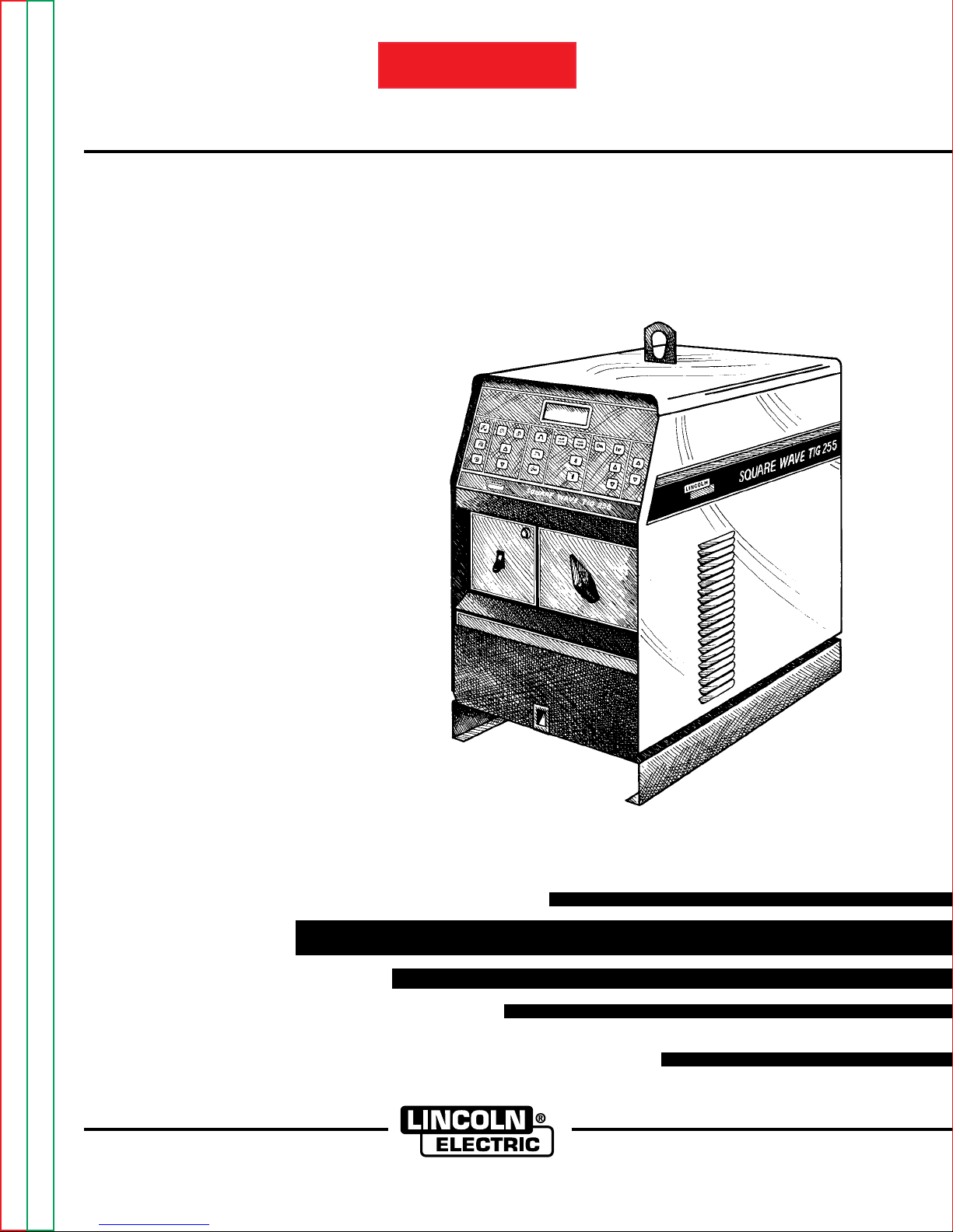
SQUARE WAVE TIG 255
Safety Depends on You
Lincoln arc welding and cutting
equipment is designed and built
with safety in mind. However, your
overall safety can be increased by
proper installation ... and thoughtful operation on your part. DO
NOT INSTALL, OPERATE OR
REPAIR THIS EQUIPMENT
WITHOUT READING THIS
MANUAL AND THE SAFETY
PRECAUTIONS CONTAINED
THROUGHOUT. And, most
importantly, think before you act
and be careful.
For use with machine Code Numbers
For use with machine Code Numbers
For use with machine Code Numbers
For use with machine Code Numbers
For use with machine Code Numbers
For use with machine Code Numbers
December 1995
10022
10023
10024
10025
10026
10134
SERVICE MANUAL
View Safety Info View Safety Info View Safety Info View Safety Info
Return to Master TOC Return to Master TOC Return to Master TOC Return to Master TOC
World's Leader in Welding and Cutting Products Premier Manufacturer of Industrial Motors
Sales and Service through Subsidiaries and Distributors Worldwide
22801 St. Clair Ave. Cleveland, Ohio 44117-1199 U.S.A. Tel. (216) 481-8100
i
SAFETY
WARNING
ARC WELDING can be hazardous.
PROTECT YOURSELF AND OTHERS FROM POSSIBLE SERIOUS INJURY OR DEATH. KEEP CHILDREN
AWAY. PACEMAKER WEARERS SHOULD CONSULT WITH THEIR DOCTOR BEFORE OPERATING.
Read and understand the following safety highlights. For additional safety information, it is strongly recommended that you purchase a copy of “Safety in Welding & Cutting - ANSI Standard Z49.1” from the American Welding Society, P.O. Box 351040,
Miami, Florida 33135 or CSA Standard W117.2-1974. A Free copy of “Arc Welding Safety” booklet E205 is available from the
Lincoln Electric Company, 22801 St. Clair Avenue, Cleveland, Ohio 44117-1199.
BE SURE THAT ALL INSTALLATION, OPERATION, MAINTENANCE AND REPAIR PROCEDURES ARE PERFORMED ONLY BY QUALIFIED INDIVIDUALS.
ELECTRIC SHOCK can
kill.
1.a. The electrode and work (or ground) circuits
are electrically “hot” when the welder is on.
Do not touch these “hot” parts with your bare
skin or wet clothing. Wear dry, hole-free
gloves to insulate hands.
1.b. Insulate yourself from work and ground using dry insulation.
Make certain the insulation is large enough to cover your full
area of physical contact with work and ground.
In addition to the normal safety precautions, if welding
must be performed under electrically hazardous
conditions (in damp locations or while wearing wet
clothing; on metal structures such as floors, gratings or
scaffolds; when in cramped positions such as sitting,
kneeling or Iying, if there is a high risk of unavoidable or
accidental contact with the workpiece or ground) use
the following equipment:
• Semiautomatic DC Constant Voltage (Wire) Welder.
• DC Manual (Stick) Welder.
• AC Welder with Reduced Voltage Control.
1.c. In semiautomatic or automatic wire welding, the electrode,
electrode reel, welding head, nozzle or semiautomatic
welding gun are also electrically “hot”.
1.d. Always be sure the work cable makes a good electrical
connection with the metal being welded. The connection
should be as close as possible to the area being welded.
1.e. Ground the work or metal to be welded to a good electrical
(earth) ground.
2.b. Use suitable clothing made from durable flame-resistant
material to protect your skin and that of your helpers from
the arc rays.
2.c. Protect other nearby personnel with suitable, non-flammable
screening and/or warn them not to watch the arc nor expose
themselves to the arc rays or to hot spatter or metal.
fumes and gases away from the breathing zone. When
welding with electrodes which require special
ventilation such as stainless or hard facing (see
instructions on container or MSDS) or on lead or
cadmium plated steel and other metals or coatings
which produce highly toxic fumes, keep exposure as
low as possible and below Threshold Limit Values (TLV)
using local exhaust or mechanical ventilation. In
confined spaces or in some circumstances, outdoors, a
respirator may be required. Additional precautions are
also required when welding on galvanized steel.
ARC RAYS can burn.
2.a. Use a shield with the proper filter and cover
plates to protect your eyes from sparks and
the rays of the arc when welding or observing
open arc welding. Headshield and filter lens
should conform to ANSI Z87. I standards.
FUMES AND GASES
can be dangerous.
3.a.Welding may produce fumes and gases
hazardous to health. Avoid breathing these
fumes and gases.When welding, keep
your head out of the fume. Use enough
ventilation and/or exhaust at the arc to keep
1.f.
Maintain the electrode holder, work clamp, welding cable and
welding machine in good, safe operating condition. Replace
damaged insulation.
1.g. Never dip the electrode in water for cooling.
1.h. Never simultaneously touch electrically “hot” parts of
electrode holders connected to two welders because voltage
between the two can be the total of the open circuit voltage
of both welders.
1.i. When working above floor level, use a safety belt to protect
yourself from a fall should you get a shock.
1.j. Also see Items 4.c. and 6.
Return to Master TOC Return to Master TOC Return to Master TOC Return to Master TOC
SQUARE WAVE TIG 255
3.b.
Do not weld in locations near chlorinated hydrocarbon
coming from degreasing, cleaning or spraying operations.
The heat and rays of the arc can react with solvent vapors
form phosgene, a highly toxic gas, and other irritating
products.
3.c. Shielding gases used for arc welding can displace air and
cause injury or death. Always use enough ventilation,
especially in confined areas, to insure breathing air is safe.
3.d. Read and understand the manufacturer’s instructions for this
equipment and the consumables to be used, including the
material safety data sheet (MSDS) and follow your
employer’s safety practices. MSDS forms are available from
your welding distributor or from the manufacturer.
3.e. Also see item 7b.
vapors
Apr. ‘93
to
SAFETY
ii
WELDING SPARKS can
cause fire or explosion.
4.a.
Remove fire hazards from the welding area.
If this is not possible, cover them to prevent
the welding sparks from starting a fire.
materials from welding can easily go through small cracks
and openings to adjacent areas. Avoid welding near
hydraulic lines. Have a fire extinguisher readily available.
4.b. Where compressed gases are to be used at the job site,
special precautions should be used to prevent hazardous
situations. Refer to “Safety in Welding and Cutting” (ANSI
Standard Z49.1) and the operating information for the
equipment being used.
4.c. When not welding, make certain no part of the electrode
circuit is touching the work or ground. Accidental contact
can cause overheating and create a fire hazard.
4.d. Do not heat, cut or weld tanks, drums or containers until the
proper steps have been taken to insure that such procedures
will not cause flammable or toxic vapors from substances
inside. They can cause an explosion even
been “cleaned”. For information, purchase “Recommended
Safe Practices for the
Containers and Piping That Have Held Hazardous
Substances”, AWS F4.1 from the American Welding Society
(see address above).
4.e. Vent hollow castings or containers before heating, cutting or
welding. They may explode.
4.f.
Sparks and spatter are thrown from the welding arc. Wear oil
free protective garments such as leather gloves, heavy shirt,
cuffless trousers, high shoes and a cap over your hair. Wear
ear plugs when welding out of position or in confined places.
Always wear safety glasses with side shields when in a
welding area.
4.g. Connect the work cable to the work as close to the welding
area as practical. Work cables connected to the building
framework or other locations away from the welding area
increase the possibility of the welding current passing
through lifting chains, crane cables or other alternate circuits. This can create fire hazards or overheat lifting chains
or cables until they fail.
4.h. Also see item 7c.
Remember that welding sparks and hot
though
they have
Preparation
for Welding and Cutting of
CYLINDER may explode
if damaged.
5.a. Use only compressed gas cylinders
containing the correct shielding gas for the
process used and properly operating
regulators designed for the gas and
pressure used. All hoses, fittings, etc. should be suitable for
the application and maintained in good condition.
5.b. Always keep cylinders in an upright position securely
chained to an undercarriage or fixed support.
5.c. Cylinders should be located:
•Away from areas where they may be struck or subjected to
physical damage.
• A safe distance from arc welding or cutting operations and
any other source of heat, sparks, or flame.
5.d. Never allow the electrode, electrode holder or any other
electrically “hot” parts to touch a cylinder.
5.e. Keep your head and face away from the cylinder valve outlet
when opening the cylinder valve.
5.f. Valve protection caps should always be in place and hand
tight except when the cylinder is in use or connected for
use.
5.g. Read and follow the instructions on compressed gas
cylinders, associated equipment, and CGA publication P-l,
“Precautions for Safe Handling of Compressed Gases in
Cylinders,” available from the Compressed Gas Association
1235 Jefferson Davis Highway, Arlington, VA 22202.
FOR ELECTRICALLY
powered equipment.
6.a.Turn off input power using the disconnect
switch at the fuse box before working on
the equipment.
6.b. Install equipment in accordance with the U.S. National
Electrical Code, all local codes and the manufacturer’s
recommendations.
6.c. Ground the equipment in accordance with the U.S. National
Electrical Code and the manufacturer’s recommendations.
Return to Master TOC Return to Master TOC Return to Master TOC Return to Master TOC
Mar. ‘93
SQUARE WAVE TIG 255
iii
SAFETY
FOR ENGINE
powered equipment.
7.a. Turn the engine off before troubleshooting and maintenance
work unless the maintenance work requires it to be running.
____________________________________________________
7.b. Operate engines in open, well-ventilated
areas or vent the engine exhaust fumes
outdoors.
____________________________________________________
7.c. Do not add the fuel near an open flame
welding arc or when the engine is running.
Stop the engine and allow it to cool before
refueling to prevent spilled fuel from
vaporizing on contact with hot engine parts
and igniting. Do not spill fuel when filling
tank. If fuel is spilled, wipe it up and do not
start engine until fumes have been
eliminated.
____________________________________________________
7.d. Keep all equipment safety guards, covers
and devices in position and in good repair.
Keep hands, hair, clothing and tools away
from V-belts, gears, fans and all other
moving parts when starting, operating or
repairing equipment.
ELECTRIC AND MAGNETIC
FIELDS
may be dangerous
8.a. Electric current flowing through any conductor causes
localized Electric and Magnetic Fields (EMF). Welding
current creates EMF fields around welding cables and
welding machines
8.b. EMF fields may interfere with some pacemakers, and
welders having a pacemaker should consult their physician
before welding.
8.c. Exposure to EMF fields in welding may have other health
effects which are now not known.
8d. All welders should use the following procedures in order to
minimize exposure to EMF fields from the welding circuit:
8.d.1.
Route the electrode and work cables together - Secure
them with tape when possible.
8.d.2. Never coil the electrode lead around your body.
8.d.3. Do not place your body between the electrode and
work cables. If the electrode cable is on your right
side, the work cable should also be on your right side.
8.d.4. Connect the work cable to the workpiece as close as
possible to the area being welded.
8.d.5. Do not work next to welding power source.
____________________________________________________
7.e. In some cases it may be necessary to remove safety
guards to perform required maintenance. Remove
guards only when necessary and replace them when the
maintenance requiring their removal is complete.
Always use the greatest care when working near moving
parts.
7.f. Do not put your hands near the engine fan. Do not
attempt to override the governor or idler by pushing on
the throttle control rods while the engine is running.
7.g. To prevent accidentally starting gasoline engines while
turning the engine or welding generator during maintenance
work, disconnect the spark plug wires, distributor cap or
magneto wire as appropriate.
___________________________________________________
7.h. To avoid scalding, do not remove the
radiator pressure cap when the engine is
hot.
Mar. ‘93
Return to Master TOC Return to Master TOC Return to Master TOC Return to Master TOC
SQUARE WAVE TIG 255

SAFETY
iv
PRÉCAUTIONS DE SÛRETÉ
Pour
votre propre protection lire et observer toutes les instructions et les précautions de sûreté specifiques qui parraissent
dans ce manuel aussi bien que les précautions de sûreté
générales suivantes:
Sûreté Pour Soudage A L’Arc
1. Protegez-vous contre la secousse électrique:
a. Les circuits à l’électrode et à la piéce sont sous tension
quand la machine à souder est en marche. Eviter toujours
tout contact entre les parties sous tension et la peau nue
ou les vétements mouillés. Porter des gants secs et sans
trous pour isoler les mains.
b. Faire trés attention de bien s’isoler de la masse quand on
soude dans des endroits humides, ou sur un plancher
metallique ou des grilles metalliques, principalement dans
les positions assis ou couché pour lesquelles une
grande partie du corps peut être en contact avec la
masse.
c. Maintenir le porte-électrode, la pince de masse, le câble
de soudage et la machine à souder en bon et sûr état
defonctionnement.
d.Ne jamais plonger le porte-électrode dans l’eau pour le
refroidir.
e. Ne jamais toucher simultanément les parties sous tension
des porte-électrodes connectés à deux machines à souder parce que la tension entre les deux pinces peut être le
total de la tension à vide des deux machines.
f. Si on utilise la machine à souder comme une source de
courant pour soudage semi-automatique, ces precautions
pour le porte-électrode s’applicuent aussi au pistolet de
soudage.
5. Toujours porter des lunettes de sécurité dans la zone de
soudage. Utiliser des lunettes avec écrans lateraux dans les
zones où l’on pique le laitier.
6. Eloigner les matériaux inflammables ou les recouvrir afin de
prévenir tout risque d’incendie dû aux étincelles.
7. Quand on ne soude pas, poser la pince à une endroit isolé de
la masse. Un court-circuit accidental peut provoquer un
échauffement et un risque d’incendie.
8. S’assurer que la masse est connectée le plus prés possible
de la zone de travail qu’il est pratique de le faire. Si on place
la masse sur la charpente de la construction ou d’autres
endroits éloignés de la zone de travail, on augmente le risque
de voir passer le courant de soudage par les chaines de levage, câbles de grue, ou autres circuits. Cela peut provoquer
des risques d’incendie ou d’echauffement des chaines et des
câbles jusqu’à ce qu’ils se rompent.
9. Assurer une ventilation suffisante dans la zone de soudage.
Ceci est particuliérement important pour le soudage de tôles
galvanisées plombées, ou cadmiées ou tout autre métal qui
produit des fumeés toxiques.
10. Ne pas souder en présence de vapeurs de chlore provenant
d’opérations de dégraissage, nettoyage ou pistolage. La
chaleur ou les rayons de l’arc peuvent réagir avec les
vapeurs du solvant pour produire du phosgéne (gas fortement toxique) ou autres produits irritants.
11. Pour obtenir de plus amples renseignements sur la sûreté,
voir le code “Code for safety in welding and cutting” CSA
Standard W 117.2-1974.
2. Dans le cas de travail au dessus du niveau du sol, se protéger contre les chutes dans le cas ou on recoit un choc. Ne
jamais enrouler le câble-électrode autour de n’importe quelle
partie du corps.
3. Un coup d’arc peut être plus sévère qu’un coup de soliel,
donc:
a. Utiliser un bon masque avec un verre filtrant approprié
ainsi qu’un verre blanc afin de se protéger les yeux du
rayonnement de l’arc et des projections quand on soude
ou quand on regarde l’arc.
b. Porter des vêtements convenables afin de protéger la
peau de soudeur et des aides contre le rayonnement de
l‘arc.
c. Protéger l’autre personnel travaillant à proximité au
soudage à l’aide d’écrans appropriés et non-inflammables.
4. Des gouttes de laitier en fusion sont émises de l’arc de
soudage. Se protéger avec des vêtements de protection
libres de l’huile, tels que les gants en cuir, chemise épaisse,
pantalons sans revers, et chaussures montantes.
Return to Master TOC Return to Master TOC Return to Master TOC Return to Master TOC
PRÉCAUTIONS DE SÛRETÉ POUR
LES MACHINES À SOUDER À
TRANSFORMATEUR ET À
REDRESSEUR
1. Relier à la terre le chassis du poste conformement au code
de l’électricité et aux recommendations du fabricant. Le dispositif de montage ou la piece à souder doit être branché à
une bonne mise à la terre.
2. Autant que possible, I’installation et l’entretien du poste
seront effectués par un électricien qualifié.
3. Avant de faires des travaux à l’interieur de poste, la
debrancher à l’interrupteur à la boite de fusibles.
4. Garder tous les couvercles et dispositifs de sûreté à leur
place.
Mar. ‘93
SQUARE WAVE TIG 255

v
RETURN TO MAIN INDEX
MASTER TABLE OF CONTENTS FOR ALL SECTIONS
Page
Safety .........................................................................................................................i-iv
Installation......................................................................................................Section A
Technical Specifications........................................................................................A-1
Location.................................................................................................................A-2
High Frequency Interference Protection................................................................A-2
Input Connections..................................................................................................A-3
Output Connections...............................................................................................A-4
Operation.........................................................................................................Section B
Safety Precautions.................................................................................................B-1
Graphic Symbols..........................................................................................B-2 – B-3
General Description...............................................................................................B-4
Design Features and Advantages .........................................................................B-4
Welding Capability.................................................................................................B-5
Limitations..............................................................................................................B-5
Controls and Settings ............................................................................................B-6
Hand and Foot Amptrol Operation.........................................................................B-8
Welding Operation .....................................................................................B-8 – B-11
Auxillary Power....................................................................................................B-11
Overload Protection.............................................................................................B-12
Accessories.....................................................................................................Section C
Maintenance ....................................................................................................Section D
Safety Precautions ................................................................................................D-1
Routine and Periodic Maintenance........................................................................D-1
General Assembly Exploded View ........................................................................D-2
Theory of Operation........................................................................................Section E
Power Supply Operation ...............................................................................E1 – E-5
SCR Operation ......................................................................................................E-6
Thermal Protection ................................................................................................E-7
Troubleshooting and Repair...........................................................................Section F
How To Use Troubleshooting Guide......................................................................F-1
PC Board Troubleshooting Procedures.................................................................F-2
Troubleshooting Guide...............................................................................F-3 – F-15
Test Procedures.......................................................................................F-17 – F-28
Oscilloscope Waveforms..........................................................................F-31 – F-39
Replacement Procedures.........................................................................F-40 – F-42
Re-Test After Repair............................................................................................F-44
Electrical Diagrams.........................................................................................Section G
Parts Manual..........................................................................................................P-241
SQUARE WAVE TIG 255

TABLE OF CONTENTS
- INSTALLATION SECTION -
Installation.......................................................................................................Section A
Technical Specifications........................................................................................A-1
Input and Output Specifications
Cable and Fuse Sizes
Physical Dimensions
Location.................................................................................................................A-2
Stacking ..........................................................................................................A-2
Tilting...............................................................................................................A-2
High Frequency Interference Protection................................................................A-2
Input Connections..................................................................................................A-3
Reconnect Procedure............................................................................................A-4
Output Connections...............................................................................................A-4
Section A
Return to Master TOC Return to Master TOC Return to Master TOC Return to Master TOC
SQUARE WAVE TIG 255
A-1
INSTALLATION
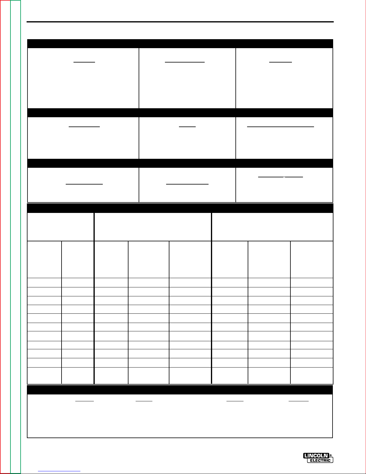
TECHNICAL SPECIFICATIONS – SQUARE WAVE TIG 255
INPUT - SINGLE PHASE ONLY
Standard
Voltage
208/230/460/1/60
230/460/575/1/60
200/240/400/1/50/60
220/380/440/1/50/60
380/415/500/1/50/60
220/380/415/1/50/60
Input Current at
Rated Output
81/74/37
74/37/30
85/77/44
77/45/39
45/41/33
77/45/41
RATED OUTPUT
(1)
Code
Number
10022
10023
10024
10025
10026
10134
Duty Cycle
40% Duty Cycle
NEMA Class II (40)
60% Duty Cycle
100% Duty Cycle
Welding Current Range
(Continuous)
5-315 Amps
AC and DC
Fuse
Input
Voltage /
Frequency
208/60
230/60
460/60
575/60
200/50/60
220/50/60
380/50/60
400/50/60
415/50/60
440/50/60
500/50/60
(Super Lag)
or Breaker
Size
125
100
50
50
125
100
70
60
60
60
50
Amps
Volts at Rated Amperes
255
200
150
OUTPUT
Constant Open
Circuit Voltage
115 Volts AC, 10 Amps
Stick OCV: 76
TIG OCV: 53
RECOMMENDED INPUT WIRE AND FUSE SIZES
For all Stick, DC TIG, and Balanced AC TIG
Welding at 255A/30V/40% Duty Cycle
Based on the 1993 US. National
Electrical Code
Type 75°C
Input
Ampere
Rating on
Nameplate
81
74
37
30
85
77
46
43
41
39
34
Type 75°C
Copper Wire in
Conduit AWG
(IEC) Sizes
6 (16mm2)
6 (16mm2)
10 (6mm2)
10 (6mm2)
6 (16mm2)
6 (16mm2)
8 (10mm2)
10 (6mm2)
10 (6mm2)
10 (6mm2)
10 (6mm2)
Copper Ground
Wire in Conduit
AWG (IEC)
Sizes
6 (16mm2)
8 (10mm2)
10 (6mm2)
10 (6mm2)
6 (16mm2)
8 (10mm2)
8 (10mm2)
10 (6mm2)
10 (6mm2)
10 (6mm2)
10 (6mm2)
For Unbalanced AC TIG Welding Above 180
Amps, 255A/16V/40% Duty Cycle, Auto
Balance Based on the 1993 U.S. National
Electrical Code
Copper Wire in
Input
Amperes
102
92
46
37
105
96
55
53
51
48
42
Conduit AWG
30
28
26
Auxiliary Power
220Volts AC, 2 Amps
(50/60 Hz. machines only)
Type 75°C
Type 75°C
(IEC) Sizes
4 (25mm2)
4 (25mm2)
8 (10mm2)
10 (6mm2)
4 (25mm2)
4 (25mm2)
8 (10mm2)
8 (10mm2)
8 (10mm2)
8 (10mm2)
10 (6mm2)
Copper Ground
Wire in Conduit
AWG (IEC)
6 (16mm2)
6 (16mm2)
10 (6mm2)
10 (6mm2)
6 (16mm2)
8 (10mm2)
8 (10mm2)
10 (6mm2)
10 (6mm2)
10 (6mm2)
10 (6mm2)
Sizes
Height Width Depth Weight
30.5 in. 19.0 in. 30.0 in.
775 mm 485 mm 760 mm
(1)
Return to Master TOC Return to Master TOC Return to Master TOC Return to Master TOC
Return to Section TOC Return to Section TOC Return to Section TOC Return to Section TOC
Unbalanced TIG welding above 180 amps will draw higher input currents; see Supply Connections section.
SQUARE WAVE TIG 255
PHYSICAL DIMENSIONS
(Lift bail, add 3.5 in) 300 lbs
(137 kg)
(Lift bail, add 90 mm)

INSTALLATION
A-2
Read entire installation section before starting
installation.
SAFETY PRECAUTIONS
WARNING
ELECTRIC SHOCK can kill.
• Only qualified personnel should
perform this installation.
• Turn the input power OFF at the
disconnect switch or fuse box
before working on this
equipment.
• Do not touch electrically hot
parts.
• Always connect the Square Wave
TIG 255 grounding terminal
(located on the bottom of the
input connection box) to a good
electrical earth ground.
SELECT SUITABLE LOCATION
HIGH FREQUENCY INTERFERENCE
PROTECTION
The spark gap oscillator in the high frequency generator, being similar to a radio transmitter, can be blamed
for many radio, TV and electronic equipment interference problems. These problems may be the result of
radiated interference. Proper grounding methods can
reduce or eliminate radiated interference.
Radiated interference can develop in the following
four ways:
1. Direct interference radiated from the welder.
2. Direct interference radiated from the welding leads.
3. Direct interference radiated from feedback into the
power lines.
4. Interference from re-radiation of “pickup” by ungrounded metallic objects.
Keeping these contributing factors in mind, installing
equipment per the following instructions should
minimize problems.
Place the welder where clean cooling air can freely
circulate in through the rear louvers and out through
the side louvers. Dirt, dust or any foreign material that
can be drawn into the welder should be kept at a
minimum. Failure to observe these precautions can
result in excessive operating temperatures and
nuisance shut-downs. Square Wave TIG 255 power
sources carry an IP23 enclosure rating. They are
rated for use in damp, dirty environments subject to
occasional falling water such as rain.
STACKING
Square Wave TIG 255’s cannot be stacked.
TILTING
Each machine must be placed on a secure, level
surface, either directly or on a recommended
undercarriage. The machine may topple over if this
procedure is not followed.
1. Keep the welder power supply lines as short as
possible and completely enclose them in rigid
metallic conduit or equivalent shielding for a
minimum distance of 50 feet (15.2m). There
should be good electrical contact between this
conduit and the welder. Both ends of the conduit
should be connected to a driven ground and the
entire length should be continuous.
2. Keep the work and electrode leads as short as
possible and as close together as possible.
Lengths should not exceed 25 ft (7.6m). Tape the
leads together when practical.
3. Be sure the torch and work cable rubber coverings
are free of cuts and cracks that allow high
frequency leakage. Cables with high natural
rubber content, such as Lincoln Stable-Arc® better
resist high frequency leakage than neoprene and
other synthetic rubber insulated cables.
Return to Master TOC Return to Master TOC Return to Master TOC Return to Master TOC
Return to Section TOC Return to Section TOC Return to Section TOC Return to Section TOC
SQUARE WAVE TIG 255
A-3
3
1
2
4
INSTALLATION
4. Keep the torch in good repair and all connections
tight to reduce high frequency leakage.
5. The work terminal must be connected to a ground
within ten feet of the welder, using one of the
following methods:
a) A metal underground water pipe in direct
contact with the earth for ten feet or more.
b) A 3/4” (19mm) galvanized pipe or a 5/8”
(16mm) solid galvanized iron, steel or copper
rod driven at least eight feet into the ground.
The ground should be securely made and the
grounding cable should be as short as possible
using cable of the same size as the work cable, or
larger. Grounding to the building frame electrical
conduit or a long pipe system can result in reradiation, effectively making these members
radiating antennas.
6. Keep all access panels and covers securely in
place.
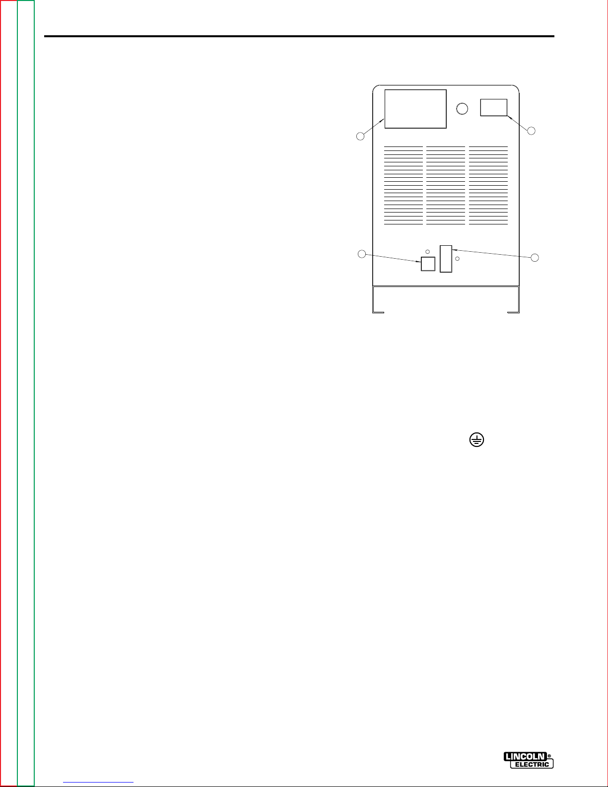
FIGURE A.1 — REAR PANEL
7. All electrical conductors within 50 ft (15.2m) of the
welder should be enclosed in grounded rigid
metallic conduit or equivalent shielding. Flexible
metallic conduit is generally not suitable.
8. When the welder is enclosed in a metal building,
several good earth driven electrical grounds (as in
5 (b) above) around the periphery of the building
are recommended.
Failure to observe these recommended installation
procedures can cause radio or TV interference
problems and result in unsatisfactory welding
performance resulting from lost high frequency
power.
INPUT CONNECTIONS
Be sure the voltage, phase, and frequency of the input
power is as specified on the rating plate, located on
the rear of the machine. Refer to Figure A.1.
1. RATING PLATE 4. 220V RECEPTACLE & BREAKER
2. INPUT ENTRY HOLE (50/60 HZ MACHINE ONLY)
3. RECONNECT PANEL 5. 115V RECEPTACLE & BREAKER
GROUND CONNECTION
The frame of the welder must be grounded. A ground
terminal marked with the symbol is located at
the bottom of the input box for this purpose. See your
local and national electrical codes for proper
grounding methods.
INPUT SUPPLY CONNECTIONS
Have a qualified electrician connect single phase input
power leads to L1 and L2 of the input panel in accordance with all local codes and national electrical
codes. Refer to the connection diagram located on the
inside of the cover of the Reconnect Panel.
Welder supply line entry provision is in the case rear
panel with a removable cover over the input
connection panel area. Entry is through a 1.7 in
(43mm) diameter hole in the case back. See Figure
A.1.
Return to Master TOC Return to Master TOC Return to Master TOC Return to Master TOC
Return to Section TOC Return to Section TOC Return to Section TOC Return to Section TOC
SQUARE WAVE TIG 255
INSTALLATION
A-4
RECONNECT PROCEDURE
On multiple input voltage welders, be sure the reconnect panel is connected per the following instructions
for the voltage being supplied to the welder.
CAUTION
Failure to follow these instructions can cause immediate failure of components within the welder.
___________________________________________
Welders are shipped connected for the highest input
voltage as listed on the rating Plate. To change this
connection for a different input voltage, reconnect the
power strap (P) to the terminal corresponding to the
input voltage used. Designations on reconnect panel,
LOW, MID and HIGH correspond to the nameplate
input voltages of a triple voltage welder. Dual voltage
welders use only LOW and HIGH. Single voltage
welders use only HIGH.
EXAMPLE: On a 208/230/460 volt welder, LOW is
208V, MID is 230V, and HIGH is 460V.
Fuse the input circuit with the recommended super lag
fuses or delay type1circuit breakers. Choose an input
and grounding wire size according to local or national
codes, refer to Specification page at the beginning of
this chapter. Using fuses or circuit breakers
smaller than recommended may result in “nuisance”
shut-offs from welder inrush currents even if not
welding at high currents.
Unbalanced AC TIG welding draws higher input
currents than those for stick, DC TIG, or Balanced AC
TIG welding. The welder is designed for these higher
input currents. However, where unbalanced AC TIG
welding above 180 amps is planned, the higher input
currents require larger input wire sizes and fuses.
Refer to Specification page at the beginning of this
chapter.
The Square Wave TIG 255 should be permanently
wired into the power system. Plugs or connectors
are not recommended.
1
Also called “inverse time” or “thermal/magnetic” circuit breakers; circuit
breakers which have a delay in tripping action that decreases as the magnitude of the current increases.
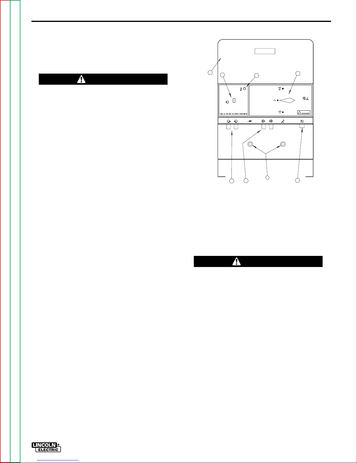
FIGURE A.2. - FRONT PANEL
1
2
I
POWER
O
WATER
IN
OUT
5
1. CONTROL AND DISPLAY AREA 5. OPTIONAL WATER SOLENOID
2. POWER SWITCH 6. GAS SOLENOID
3. THERMOSTATIC 7. WORK (LEFT) AND
PROTECTION LIGHT ELECTRODE TERMINALS
4. POLARITY SWITCH 8. REMOTE RECEPTACLE
3
DC
AC
DC
GAS
WORK
OUT
IN
6
7
ELECTRODE
4
L9119-1
DO NOT SWITCH
WHILE WELDING
WARNING
L9119-2
REMOTE
8
OUTPUT CONNECTIONS
WARNING
To avoid receiving a high frequency shock, keep the
TIG torch and cables in good condition.
___________________________________________
See Figure A.2 for the location of the work and
electrode terminals, the gas and optional water
solenoids, and the Remote Receptacle.
TIG TORCH CONNECTION
TIG welding torches come with 12.5 ft (3.8m) and 25 ft
(7.6m) cables. Use the shorter length whenever
possible to minimize possible radio interference
problems. With power source off, connect the torch
cable to the “Electrode” terminal on the welder.
Connect a separate work cable to the “Work” terminal
of the welder. See Table A.1 for recommended work
cable sizes. Both work and electrode cables should be
routed through the cable strain relief holes provided in
the base directly below the welding output terminals.
Return to Master TOC Return to Master TOC Return to Master TOC Return to Master TOC
Return to Section TOC Return to Section TOC Return to Section TOC Return to Section TOC
SQUARE WAVE TIG 255

A-5
INSTALLATION
TABLE A.1
Cable Sizes for Combined Lengths of Copper
Electrode and Work Cable
Machine Size
255 Amp
40% Duty Cycle #2 (35mm2) #1 (45mm2) 1/0 (55mm2)
Lengths up to
100 ft 100 to 200 ft 200 to 250 ft
Connect the TIG torch gas and water fittings to the
welder fittings. Any torch with fittings that conform to
Compressed Gas Association (CGA) standards can be
used.
The welder fittings have the following threads: Gas
Inlet and Outlet: 5/8”-18 right-hand female; Water inlet
and Outlet: 5/8”-18 left-hand female. The cylinder of
inert shielding gas must be equipped with a pressure
regulator and flow meter. Install a hose between the
flow meter and gas inlet on the welder.
WARNING
Observe the safety precautions necessary for handling and using compressed gas containers. Contact
your supplier for specific information.
___________________________________________
STICK ELECTRODE CABLE CONNECTION
Turn the Power switch Off. Run the electrode and
work cables through the strain relief holes below the
welding output terminals, and connect the cables to
the proper terminals. This strain relief prevents damage to the welding output terminals if the cables are
pulled excessively. Select cable size according to
Table A.1.
WARNING
Do not connect a TIG torch and stick electrode cable
at the same time. They will both be electrically HOT
whenever the output contactor is energized.
___________________________________________
DO NOT operate a water-cooled torch unless water is
flowing. Water doesn’t flow until solenoid is actuated.
If using a water-cooled torch with a Magnum water
cooler, connect the cooler water outlet to the ‘Water
Valve In” fitting. Connect the TIG torch inlet to the
“Water Valve Out” fitting.
If using a water-cooled torch with a free-running water
supply, install a water line between the welder “Water
Inlet” and the supply. Include a strainer in the water
supply line to prevent dirt particles from obstructing
water flow in the valve and cooling chamber of the
TIG torch. Failure to do so could result in water valve
malfunction and overheating of the water-cooled
torch. Connect the torch water line to the welder
“Water Out” fitting. Use a nonmetallic drain line from
the electrode connection to the drain or water recirculating pump.
For other water coolers or torches, consult the manufacturer’s instructions for the water cooler or TIG torch
being used.
Return to Master TOC Return to Master TOC Return to Master TOC Return to Master TOC
Return to Section TOC Return to Section TOC Return to Section TOC Return to Section TOC
SQUARE WAVE TIG 255

TABLE OF CONTENTS
- OPERATION SECTION -
Operation..........................................................................................................Section B
Safety Precautions.................................................................................................B-1
Graphic Symbols..........................................................................................B-2 - B-3
General Description ...............................................................................................B-4
Design Features and Advantages..........................................................................B-4
Welding Capability .................................................................................................B-5
Limitations..............................................................................................................B-5
Controls and Settings.............................................................................................B-6
Control Panel Keys .........................................................................................B-6
Case Front Controls........................................................................................B-7
Hand and Foot Amptrol Operation.........................................................................B-8
Welding Operation.......................................................................................B-8 - B-11
TIG Welding Guidelines..................................................................................B-8
TIG Welding Sequence of Operation (2-Step Mode)......................................B-9
TIG Welding Sequence of Operation (4-Step Mode)....................................B-10
Advanced Tig Welding Features...................................................................B-11
Auxillary Power ....................................................................................................B-11
Overload Protection .............................................................................................B-12
Section B
Return to Master TOC Return to Master TOC Return to Master TOC Return to Master TOC
SQUARE WAVE TIG 255
B-1
OPERATION
OPERATING INSTRUCTIONS
Read and understand entire section before operating
machine.
GENERAL WARNINGS
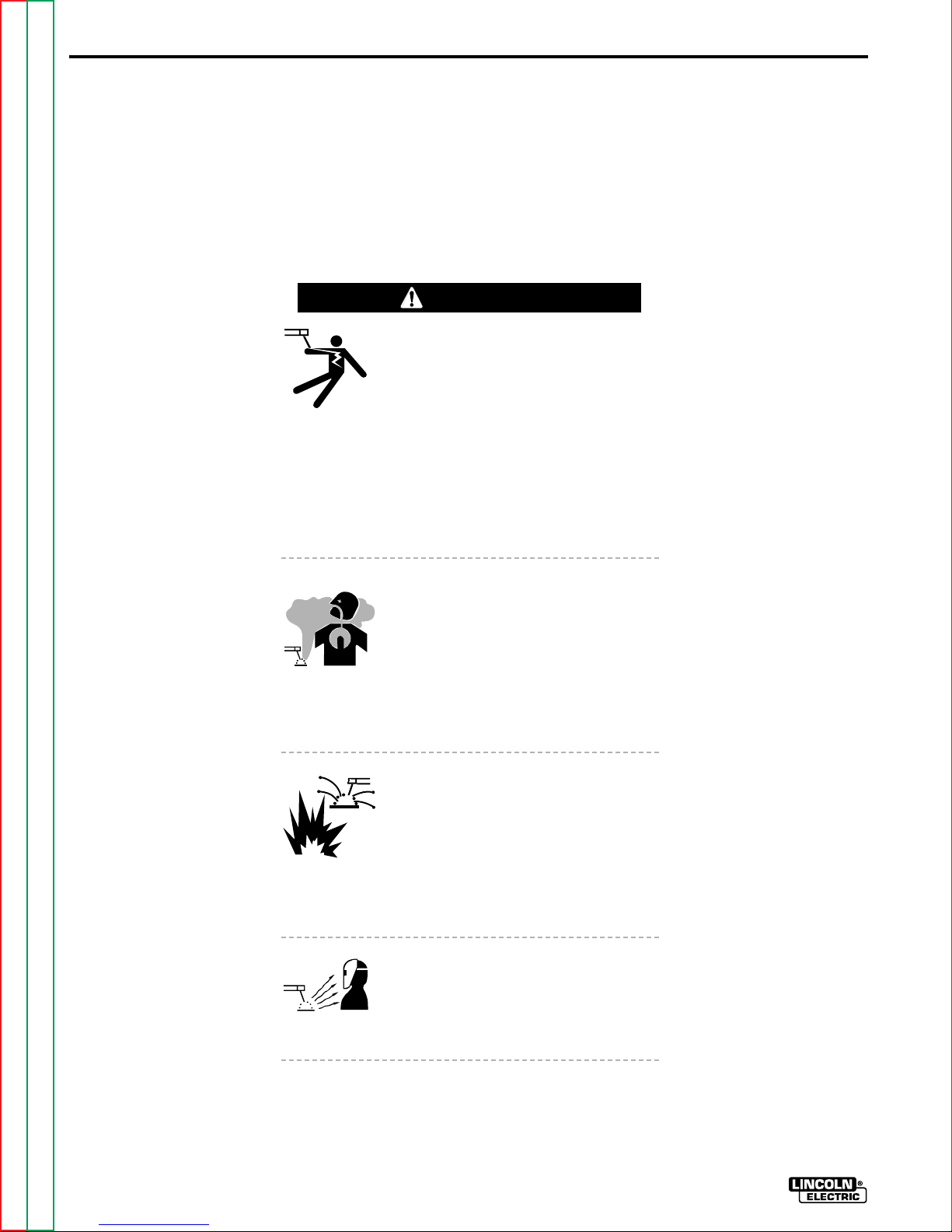
SAFETY PRECAUTIONS
WARNING
ELECTRIC SHOCK
can kill.
• Do not touch electrically live parts
or electrode with skin or wet
clothing.
• Insulate yourself from work and
ground.
• Always wear dry insulating
gloves.
FUMES AND GASES
can be dangerous.
• Keep your head out of fumes.
• Use ventilation or exhaust to
remove fumes from breathing
zone.
WELDING SPARKS
can cause fire or
explosion
• Keep flammable material away.
• Do not weld on containers that
have held combustibles.
ARC RAYS
can burn.
Observe additional Safety Guidelines detailed in
the beginning of this manual.
Return to Master TOC Return to Master TOC Return to Master TOC Return to Master TOC
Return to Section TOC Return to Section TOC Return to Section TOC Return to Section TOC
SQUARE WAVE TIG 255
• Wear eye, ear and body
protection.

OPERATION
GRAPHIC SYMBOLS THAT APPEAR ON
THIS MACHINE OR IN THIS MANUAL
B-2
&
TIG 2-STEP
TIG 4-STEP
STICK
CURRENT
CONTROL
OUTPUT
LOCAL CUR-
RENT CON-
TROL
2
AFTERFLOW /
AFTERFLOW
TIME
CONTINUOUS
HIGH FRE-
QUENCY
START ONLY
HIGH FRE-
QUENCY
OFF
A
HF
REMOTE CUR-
RENT CON-
TROL
INCREASE
OUTPUT
DECREASE
HIGH FRE-
QUENCY
&
&
ON
CLEAN
(INCREASE
POSITIVE
POLARITY)
PENETRATE
(INCREASE
NEGATIVE
POLARITY)
TIG PULSER
Return to Master TOC Return to Master TOC Return to Master TOC Return to Master TOC
Return to Section TOC Return to Section TOC Return to Section TOC Return to Section TOC
SQUARE WAVE TIG 255

B-3
OPERATION
GRAPHIC SYMBOLS THAT APPEAR ON
THIS MACHINE OR IN THIS MANUAL (CONT.)
AC WAVE BAL-
ANCE
GAS OUTPUT
f
&
&
PULSED PER
SECOND
OVER TEMPER-
ATURE
INPUT
POWER
DC+
POLARITY
DC-
POLARITY
DO NOT
GAS INPUT
ELECTRODE
CONNECTION
PROTECTIVE
GROUND
SINGLE PHASE
TRANSFORMER
AC & DC RECTI-
FIER POWER
SOURCE
Return to Master TOC Return to Master TOC Return to Master TOC Return to Master TOC
Return to Section TOC Return to Section TOC Return to Section TOC Return to Section TOC
SWITCH
WHILE WELD-
ING
WARNING
WATER
(COOLANT)
OUTPUT
WATER
(COOLANT)
INPUT
TIG (GTAW)
SINGLE
PHASE
WORK CONNEC-
TION
AC POLARITY
SQUARE WAVE TIG 255

OPERATION
B-4
GENERAL DESCRIPTION
The Square Wave TIG 255 is a constant current,
single range square wave AC/DC TIG (GTAW) arc
welding power source with built-in high frequency
stabilization. It also has stick (SMAW) capability. It is
available from the factory in one model only; there are
no factory installed options, only variations in input
voltage and frequency.
The Square Wave TIG 255 includes advanced
features such as Auto-Balance™, 2-Step/4-Step Arc
Start Switch operation and a TIG pulser. In addition,
fixed preflow and variable afterflow timers are
included for shielding gas and cooling water control.
RECOMMENDED PROCESSES AND
EQUIPMENT
The Square Wave TIG 255 is recommended for the
TIG (GTAW) and stick (SMAW) welding processes
within its output capacity of 5 to 315 amps, on both
AC and DC polarity. It is compatible with all Magnum
TIG accessories (see Accessory section in this manual), as well as many industry standard items, such as
TIG torches, hoses, and water coolers.
• Welding current limit can be preset from 5 to 315
amps and is displayed on the Ammeter when not
welding.
• Auto Balance circuitry automatically provides the
proper amount of cleaning and penetration when
AC TIG welding. Manual AC wave balance adjustment is also possible.
• 2-Step/4-Step Arc Start Switch Capability.
• TIG Pulser with On/Off Selection, and Pulses Per
Second adjustment. Background current and duty
cycle are automatically adjusted according to the
peak welding current.
• Fixed preflow time of 0.5 seconds. Preflow time is
eliminated if welding restarts during gas afterflow of
previous weld. This avoids unnecessary delays
when making repeated welds.
• Adjustable afterflow time control.
• Local/Remote current selection.
• Stick/TlG selection.
• Continuous/Start/Off High Frequency selection.
• DC+/AC/DC- Polarity Switch.
OPERATIONAL FEATURES AND
CONTROLS
The Square Wave TIG 255 has the following controls
as standard: TIG 2-Step/TlG 4-Step/Stick mode selection, Local/Remote current control selection,
Continuous/Start Only/Off high frequency selection,
Auto/Manual AC wave balance selection with the
manual wave balance adjustment, TIG pulser On/Off
selection with frequency adjustment, afterflow adjustment, and DC+/DC-/AC polarity selection.
DESIGN FEATURES AND
ADVANTAGES
• Designed to NEMA EW-1 & International IEC-974
Standards.
• Single output range of 5-315 amps covers the
majority of all TIG welding applications.
• Solid State Output Contactor: no noise, no parts to
wear.
• Digital Ammeter and Voltmeter for precise readings
Return to Master TOC Return to Master TOC Return to Master TOC Return to Master TOC
Return to Section TOC Return to Section TOC Return to Section TOC Return to Section TOC
from 5 to 315 amps welding.
•
Power Factor Correction for lower input currents and
smaller input wire sizes.
• Remote Receptacle for Amptrol or Arc Start Switch.
• Low Voltage Arc Start Switch Circuit (24 V AC) for
maximum operator safety.
• Gas and optional Water Valves: Inlet & outlet fittings
conform to Compressed Gas Association (CGA)
standards.
• Built-in High Frequency Generator.
• 115 Volt Receptacle with 10 amp Circuit Breaker.
• 220 Volt European (Schuko) type receptacle with 2
amp circuit breaker for water coolers (50/60Hz
machines only).
• Excellent arc starting and stability up through 315
amps.
• High resistance to AC arc rectification.
• No tungsten spitting within current range of
electrode.
• Compact size, requires only a 19 in x 30 in
(485 mm x 760 mm) footprint.
SQUARE WAVE TIG 255

B-5
• Strain relief holes in base for welding cables, gas
and water hoses and control cables.
• Easy access for input connections. Connections
are simple strip and clamp of input wires (no lugs
required).
• Low fan noise at idle.
• Modular construction for easy servicing.
• Simple keypad layout allows even novice users to
operate with minimal instruction.
• Unused controls are automatically locked out to
simplify setup. Examples: the AC wave balance
control has no effect in DC; the High Frequency and
gas and water valves do not operate in Stick mode;
TIG Pulser is locked out in the Stick mode.
• Recessed panels protect controls, output terminals
gas and water fittings.
OPERATION
• Large safety margins and protective circuits protect
rectifiers from transient voltages and high currents.
• Line Voltage Compensated.
• Thermostatically Protected.
• Electronic Over Current Protection.
WELDING CAPABILITY
The Square Wave TIG 255 is rated at 255 amps, 30
volts, at 40% duty cycle on a ten minute basis. It is
capable of higher duty cycles at lower output currents.
If the duty cycle(s) are exceeded, a thermal protector
will shut off the output until the machine cools to a
reasonable operating temperature.
LIMITATIONS
The Square Wave TIG 255 is not recommended for
arc gouging due to its limited output capacity.
The Square Wave TIG 255 is not recommended for
AC TIG welding when high concentrations of helium
are used for shielding; starting problems and arc rectification may occur.
The Square Wave TIG 255 is not recommended for
pipe thawing.
Return to Master TOC Return to Master TOC Return to Master TOC Return to Master TOC
Return to Section TOC Return to Section TOC Return to Section TOC Return to Section TOC
SQUARE WAVE TIG 255
OPERATION
B-6
CONTROLS AND SETTINGS
All operator controls and adjustments are located on the case front of the Square Wave TIG 255. Refer to Figures
B.1, B.2.a and B.2.b and corresponding explanations.
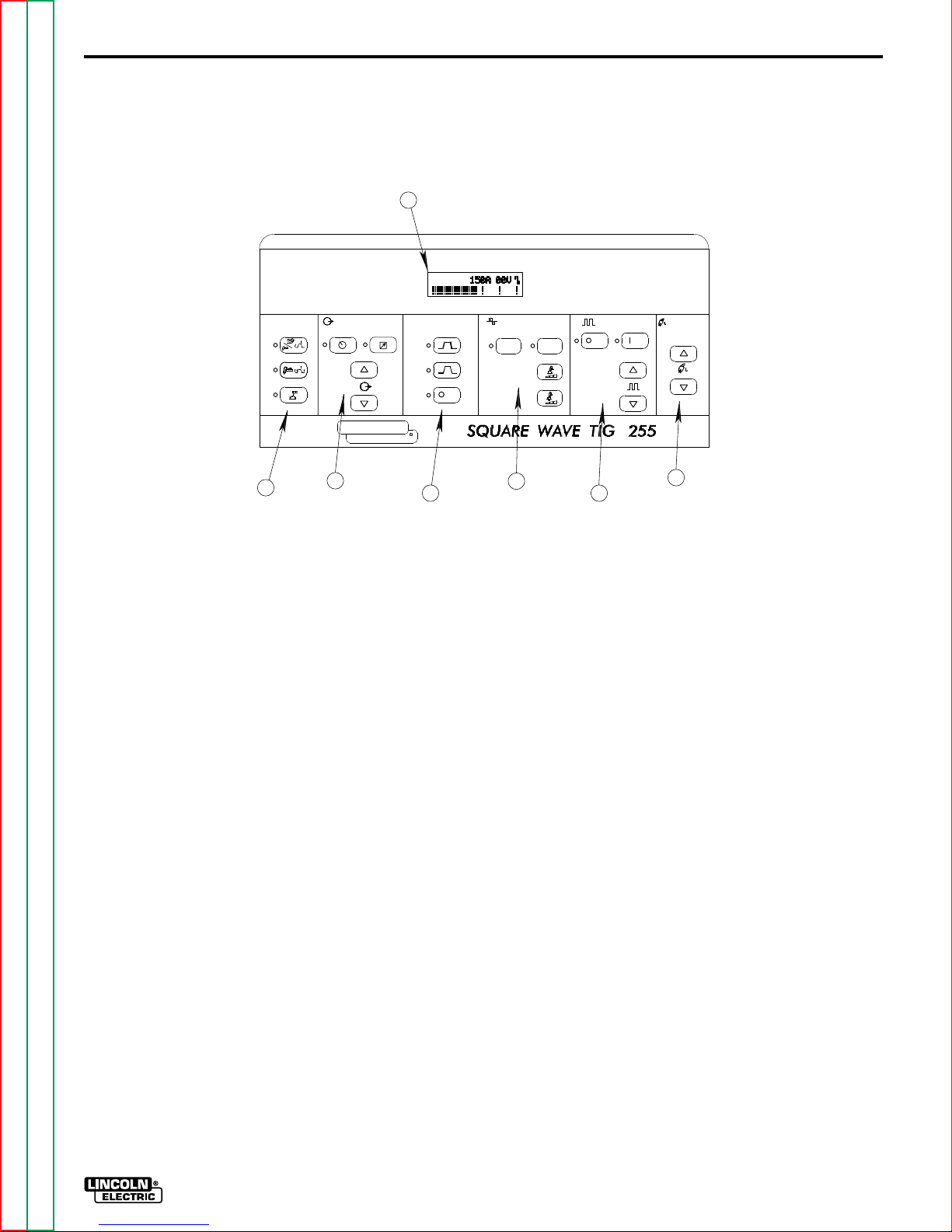
FIGURE B.1 - CONTROL PANEL KEYS
7
CONTROL PANEL KEYS
The keys are grouped into six areas, described below
and in Figure B.1. Some areas are active in both TIG
and Stick, while others are active in TIG only. The red
LED indicator lights are used to tell which functions
are active, and the display (Item 1) is used to check
the settings of the up/down keys.
1. WELD MODE KEYS: These keys select the Weld
Mode desired: TIG 2-Step, TIG 4-Step, or Stick.
Read the complete Operating Instructions section
for more information on TIG 2-Step and TIG 4Step.
2. CURRENT CONTROL: These keys select Local
or Remote and adjust the Amps Up or Amps
Down. These keys are used to set thewelding current from 5 to 315 amps, as well as to select Local
or Remote control. Local control allows the current
to be adjusted only with the Amps Up/Amps Down
keys. Remote control allows the use of a hand or
foot operated remote control. Read the complete
Operating Instructions
on Local and Remote.
3. HIGH FREQUENCY: These keys are active in the
TIG mode only. Select from Continuous, Start
Only, or Off. Read the TIG Welding Section for
Return to Master TOC Return to Master TOC Return to Master TOC Return to Master TOC
Return to Section TOC Return to Section TOC Return to Section TOC Return to Section TOC
information on High Frequency.
THE LINCOLN ELECTRIC COMPANY CLEVELAND, OHIO USA
WELD MODE
1
TIG 2-STEP
TIG 4-STEP
STICK
CURRENT CONTROL
LOCAL
AMPS
A
LINCOLN
ELECTRIC
2
REMOTE
HIGH FREQUENCY
HF
R
3
1. WELD MODE KEYS 5. TIG PULSER KEYS
2. CURRENT CONTROL KEYS 6. AFTERFLOW KEYS
3. HIGH FREQUENCY KEYS 7. DISPLAY
4. AC WAVE BALANCE KEYS
section for more information
CONTINUOUS
HF
START ONLY
HF
2
AFTERFLOW
SECONDS
6
G2612
2
AC/DC OUTPUT CAPACITY: 255 AMPS 30 VOLTS 40% DUTY CYCLE
AC WAVE BALANCE
MANUAL
AUTO-
BALANCE
BALANCE
CLEAN
OFF
PENETRATE
4
TIG PULSER
OFF
5
ON
PULSES PER SECOND
f
4. AC WAVE BALANCE: These keys are active in
the AC TIG mode only. They are used to set the
amount of cleaning and/or penetration produced
during an AC TIG weld. Auto Balance™
automatically sets the AC Wave Balance according
to the welding current. If manual adjustment is
desired, the Manual Balance key can be pressed,
and the balance adjusted from +5 (cleaning) to -10
(penetration) with the Cleaning and Penetration
keys. Read the Advanced Features section for a
complete explanation of the AC Wave Balance.
5. TIG PULSER: These keys are active in the TIG
mode only. The On/Off keys turn the TIG Pulser
on and off. The Pulses Per Second keys adjust
the pulsing frequency up and down, from 0.5 to 10
pulses per second. Read the Advanced Features
section for more information on the TIG Pulser.
6. AFTERFLOW: These keys are active in the TIG
mode only. They must adjust the afterflow time
from 5 to 50 seconds for shielding gas and cooling
water flow through solenoids located on the case
front. As the Afterflow time is adjusted, the
Afterflow time, in seconds, is shown in the
Momentary Display.
SQUARE WAVE TIG 255
B-7
OPERATION
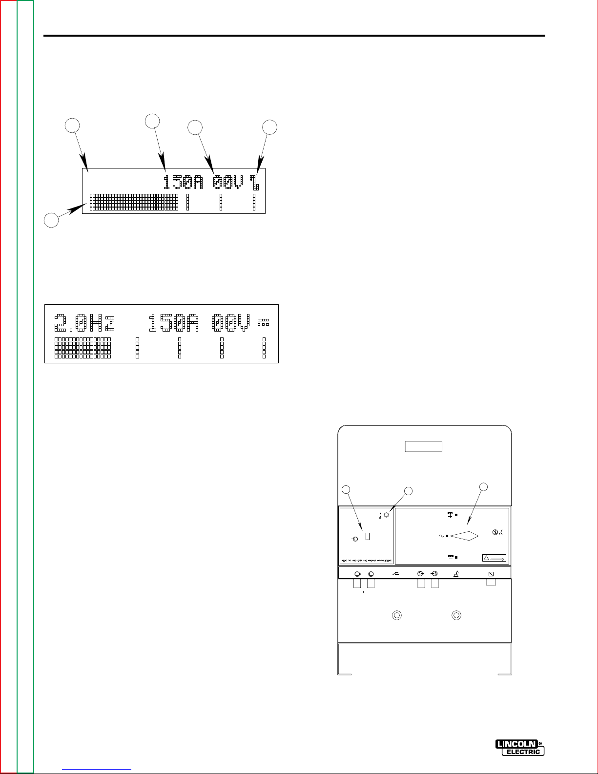
7. CONTROL PANEL: The display is divided into five
sections. See Figures B.2.a and B.2.b.
FIGURE B.2.a - DISPLAY
D
E
A. AC/DC INDICATOR D. MOMENTARY DISPLAY
B. VOLTMETER E. BAR GRAPH
C. AMMETER
C
B
A
FIGURE B.2.b - DISPLAY
and on the Momentary Display. When the Momentary
Display is blank (as in Figure B.2.a), the
Display represents values shown on the
Bar Graph
ammeter.
When a low value is shown on the ammeter, only a
few “bars” will appear on the left hand side of the Bar
Graph Display. As the ammeter value increases, more
and more “bars” will appear. Whenever a value
increases, more and more “bars” will appear.
Whenever a value appears in the Momentary Display,
the Bar Graph Display will represent the Momentary
Display value, not the ammeter value.
CASE FRONT CONTROLS
Refer to Figure B.3 for the location of the following
controls:
1. POWER SWITCH: Controls the input power to the
Square Wave TIG 255.
2. OVER TEMPERATURE LIGHT: A yellow light
which only lights when an over temperature
situation occurs. See the Maintenance Section for
more information on the thermostatic protection.
A. AC/DC INDICATOR: This symbol represents the
output polarity of the 255 . . . either AC or DC. AC
is shown in Figure B.2.a; DC is shown in Figure
B.2.b.
B. VOLTMETER: This meter displays open circuit
voltage as well as welding voltage, as measured
on the output studs of the Square Wave TIG 255.
C. AMMETER: The ammeter can display preset
current (for setting the welding current before
welding) and actual welding current (the value of
the welding current during a weld).
D. MOMENTARY DISPLAY: This area is blank under
most conditions; see Figure B.2.a. Different values may be displayed here as certain keypad
keys are pressed. See Figure B.2.b; the TIG
Pulser is being adjusted, so the Pulse Frequency,
2.0 Hz, is being displayed. Information in the
Momentary Display lasts for five seconds after a
key is pressed. Read the complete Operating
Instructions section for more information on the
values that appear in the Momentary Display.
E. BAR GRAPH DISPLAY: This area provides a
graphical display of values shown on the Ammeter
Return to Master TOC Return to Master TOC Return to Master TOC Return to Master TOC
Return to Section TOC Return to Section TOC Return to Section TOC Return to Section TOC
3. POLARITY SWITCH: Selects DC+, AC or DCwelding polarity. DO NOT SWITCH UNDER
LOAD.
FIGURE B.3 - CASE FRONT CONTROLS
1
I
POWER
O
WATER
IN
OUT
2
DC
AC
DC
GAS
WORK
OUT
1. POWER SWITCH
2. THERMOSTATIC
PROTECTION LIGHT
3. POLARITY SWITCH
ELECTRODE
IN
3
L9119-1
DO NOT SWITCH
WHILE WELDING
WARNING
L9119-2
REMOTE
SQUARE WAVE TIG 255

OPERATION
B-8
HAND AND FOOT AMPTROL
ACCESSORY OPERATION
Both the Hand and Foot Amptrol work in a similar
manner. They are meant to be used for remote current
control when Remote Current Control is selected.
The TIG 2-Step mode must be selected when using
an Amptrol for remote current control. As explained
below, Amptrols can also be used as arc start
switches if Local Current Control is selected.
For simplicity, the following explanation will refer only
to “Amptrols”, meaning both Foot and Hand models.
The term “minimum” refers to a Foot pedal in the “up”
position, as it would be with no foot pressure, or a
Hand Amptrol in the relaxed position, with no thumb
pressure. “Maximum” refers to a fully depressed Foot
Amptrol, or a fully extended Hand Amptrol.
The Amptrol is capable of controlling the output
current from 5 amps to the preset current displayed on
the ammeter. For example, if the ammeter is preset
for 200 amps and the Current Control switch is in the
REMOTE position, the Amptrol, when depressed just
past its minimum position, will cause the Square
Wave TIG 255 to weld at 5 amps. At the Amptrols
maximum position, the output would be near 200
amps.
It is important to note that, for many applications, the
tungsten will not start an arc at only 5 amps. To start
an arc reliably, it is important to depress the Amptrol
far enough so that the machine output current is near
the tungsten operating range. In the example above, a
3/32” tungsten may be used on DC- to weld near 200
amps. To start the weld, the operator may have to
depress the Amptrol approximately 1/4 of the way
down, or to nearly 50 amps, in order to start the arc.
Merely depressing the Amptrol to its 5 amp minimum
position will not start the arc.
WELDING OPERATION
TIG WELDING
Familiarize yourself with the Controls and Display
Section before attempting operation of the Square
Wave TIG 255.
TIG WELDING GUIDELINES
TIG welding can be done in either the TIG 2-Step or
the TIG 4-Step Weld Mode. TIG 2-Step is typically
used with Hand or Foot Amptrols, with Remote
Current control. TIG 4-Step is typically used with Arc
Start switches and Local Current Control, because it
provides a very brief current upslope, and a 5-second
current downslope. TIG 4-Step also functions like a
trigger interlock, making it unnecessary to hold down
the Arc Start switch during a weld. Read the TIG
Welding Sequence of Operation sections for more
details on 2-Step and 4-Step Operation.
Refer to Table B.2 for guidelines on electrode sizes,
torch nozzles and shielding gas flow rates.
TABLE B.1
RECOMMENDED POLARITY SETTINGS FOR
TIG WELDING
Type of Welding
Stainless Steel
Aluminum & Magnesium
Other Metals
Electrode
Polarity
DC-
AC
DC-
High Frequency
Setting
START
CONTINUOUS
START
If the Current Control switch is set to the LOCAL
position, an Amptrol can be used as an arc start
switch. Depressing the Amptrol just past minimum will
cause the Amptrols built-in arc start switch to close,
and backing off completely causes the built-in start
switch to open. The Amptrol will have no effect on the
welding current when used as an arc start switch.
Return to Master TOC Return to Master TOC Return to Master TOC Return to Master TOC
Return to Section TOC Return to Section TOC Return to Section TOC Return to Section TOC
SQUARE WAVE TIG 255

B-9
OPERATION
TABLE B.2
1%, 2%
2-15
5-20
15-80
70-150
(1)
FOR TUNGSTEN ELECTRODES
AC Approximate Argon
1%, 2%
Pure
Tungsten
2-15
10-20
20-30
30-80
60-130
100-180
100-240
190-300
250-400
Thoriated
Tungsten
Zirconiated Aluminum
---
5-20
20-60
60-120
100-180
160-250
200-320
290-390
340-525
3-8 (2-4)
5-10 (3-5)
5-10 (3-5)
5-10 (3-5)
13-17 (6-8)
15-23 (7-11)
21-25 (10-12)
23-27 (11-13)
28-32 (13-15)
TYPICAL CURRENT RANGES
DCEN (-) DCEP ( +)
Tungsten
Electrode
Diameter
in. (mm)
.010 (.25)
0.020 (.50)
0.040 (1.0)
1/16 (1.6)
3/32 (2.4)
1/8 (3.2)
5/32 (4.0)
3/16 (4.8)
1/4 (6.4)
(1) When used with argon gas. The current ranges shown must be reduced when using argon/helium or pure helium shielding gasses.
(2) Tungsten electrodes are classified as follows by the American Welding Society (AWS):
Pure . . . . . . . . . . . . . . . EWP
1% Thoriated . . . . . . . . EWTh-1
2% Thoriated . . . . . . . . EWTh-2
Though not yet recognized by the AWS, Ceriated Tungsten is now widely accepted as a substitute for 2% Thoriated Tungsten in AC and DC applications.
(3) DCEP is not commonly used in these sizes.
(4) TIG torch nozzle “sizes” are in multiples of 1/16ths of an inch:
#10 = 5/8 in. (16 mm)
(5) TIG torch nozzles are typically made from alumina ceramic. Special applications may require lava nozzles, which are less prone to breakage, but cannot with-
stand high temperatures and high duty cycles.
1%, 2%
Thoriated
Tungsten
1%, 2%
Thoriated
Tungsten
2-15
5-20
15-80
70-150
150-250
250-400
400-500
500-750
750-1000
#4 = 1/4 in. (6 mm)
#5 = 5/16 in. (8 mm)
#6 = 3/8 in. (10 mm)
#7 = 7/16 in. (11 mm)
#8 = 1/2 in. (12.5 mm)
10-20
15-30
25-40
40-55
55-80
80-125
(3)
(3)
(3)
Unbalanced Wave Balanced Wave
Pure
Tungsten
Thoriated
Tungsten
Zirconiated
2-15
5-15
10-60
50-100
100-160
150-210
200-275
250-350
325-450
140-235
225-325
300-400
400-500
500-630
(2)
Gas Flow Rate
C.F.H. (1/min.)
Stainless
Steel
3-8 (2-4)
5-10 (3-5)
5-10 (3-5)
9-13 (4-6)
11-15 (5-7)
11-15 (5-7)
13-17 (6-8)
18-22 (8-10)
23-27(11-13)
TIG Torch
Nozzle
(4), (5)
Size
#4, #5, #6
#5, #6
#6, #7, #8
#8, #10
TIG WELDING SEQUENCE OF
OPERATION (2-STEP MODE)
In TIG 2-Step Mode the welding arc is established by
depressing the Arc Start Switch or Amptrol (Step 1).
Output continues as long as the switch or Amptrol is
depressed. Releasing the switch or Amptrol (Step 2)
turns off the arc. Hence the name 2-Step Mode.
1. Connect an Arc Start Switch or an Amptrol to the
Remote Receptacle.
2.
Turn on the welder, gas supply and water supply (if
so
equipped). The Control Panel Display and
red LEDS will illuminate when the power is on.
3. Select the TIG 2-Step Weld Mode.
4. Select Local (if using an Arc Start Switch) or
Remote (if using an Amptrol) current control. Set
the output current using the Amps Up/Down keys.
The output current setting will be displayed on the
Ammeter.
Return to Master TOC Return to Master TOC Return to Master TOC Return to Master TOC
Return to Section TOC Return to Section TOC Return to Section TOC Return to Section TOC
5. Select Continuous High Frequency if welding with
AC polarity, or Start Only High Frequency if
welding with DC- polarity. High Frequency Off can
be used for scratch start welding.
6. Select AC or DC- electrode polarity. See Table
B.1.
7. If welding with AC polarity, select Auto Balance™.
This gives the optimum ratio between cleaning and
penetration, automatically adjusted for the output
current. If manual adjustment of the AC Wave
Balance is desired, select Manual Balance, and
adjust the wave balance with the Cleaning and
Penetration keys. See the Advanced Features
section for more information on setting and using
the AC Wave Balance.
8. Select TIG Pulser On or Off. If the TIG Pulser is
on, adjust the pulse frequency with the Pulses
Per Second Up/Down keys. See the Advanced
Features section for more information on setting
and using the TIG Pulser.
SQUARE WAVE TIG 255
12/95

OPERATION
B-10
9. Set the Afterflow time with the Seconds Up/Down
keys. Afterflow time provides shielding gas flow
(and cooling water, if used) after the weld. Use
short Afterflow times with low currents and small
tungstens, use long afterflow times at high output
currents with large tungstens.
10. Press and release the Arc Start Switch, and set
the gas flow meter. The welder is now ready for
welding.
11. Position the tungsten electrode at the start of the
weld at a 65° to 75° angle with the horizontal so
that the electrode is approximately 1/8” (4mm)
above the work piece. Press the Arc Start Switch.
This opens the gas and water valves to automatically purge air from the hose and torch. After a 0.5
second preflow time, the high frequency becomes
available to strike the arc.
12. Hold the Arc Start Switch or Amptrol down until an
arc is established. If using an Amptrol, read the
section on Hand and Foot Amptrol Operation.
Release the Arc Start Switch or Amptrol to stop
the arc and start the Afterflow timer. After the
Afterflow time has expired, the gas and water
valves will close. To make another weld, repeat
steps 11 and 12.
5. Select Continuous High Frequency if welding with
AC polarity, or Start Only High Frequency if
welding with DC- polarity. High Frequency Off can
be used for scratch start welding.
6. Select AC or DC- electrode polarity. See Table
B.1.
7. If welding with AC polarity, select Auto Balance™.
This gives the optimum ratio between cleaning and
penetration, automatically adjusted for the output
current. If manual adjustment of the AC Wave
Balance is desired, select Manual Balance, and
adjust the wave balance with the Cleaning and
Penetration keys. See the Advanced Features
section for more information on setting and using
the AC Wave Balance.
8. Select TIG Pulser On or Off. If the TIG Pulser is
on, adjust the pulse frequency with the Pulses Per
Second Up/Down keys. See the Advanced
Features section for more information on setting
and using the TIG Pulser.
9. Set the Afterflow time with the Seconds Up/Down
keys. Afterflow time provides shielding gas flow
(and cooling water, if used) after the weld. Use
short Afterflow times with low currents and small
tungstens, long afterflow times at high output
currents with large tungstens.
TIG WELDING SEQUENCE OF
OPERATION (4-STEP MODE)
TIG 4-Step Mode funcitons like a trigger interlock,
making it unnecessary to hold down the Arc Start
Switch during welding. By depressing the Arc Start
Switch a first time, the arc will start at a low current
(step 1). By releasing the Arc Start Switch (step 2) the
output ramps up to welding current. Depressing the
Arc Start Siwtch a second time (step 3) initiates a
welding current downslope. Releasing the Arc Start
Switch (step 4) stops the arc. Hence the name “4-Step
Mode”
1. Connect an Arc Start Switch to the Remote
Receptacle.
2.
Turn the welder, gas supply and water supply (if so
equipped), on. The Control Panel Display and red
lights will illuminate when the power is on.
3. Select the TIG 4-Step Weld Mode.
4. Select the Local current control. Set the output
current
current
Return to Master TOC Return to Master TOC Return to Master TOC Return to Master TOC
Return to Section TOC Return to Section TOC Return to Section TOC Return to Section TOC
using the Amps Up/Down keys. The output
setting will be displayed on the Ammeter.
10. Press and release the Arc Start Switch, and set
the gas flow meter. The welder is now ready for
welding.
11. Position the tungsten electrode at the start of the
weld at a 65° to 75° angle with the horizontal so
that the electrode is approximately 1/8” (4mm)
above the work piece. Press the Arc Start Switch.
This opens the gas and water valves to
automatically purge air from the hose and torch.
After a 0.5 second preflow time, the high
frequency becomes available to strike the arc.
12. Hold the Arc Start Switch down until an arc is
established. The arc will start at a low current
value. Release the Arc Start Switch. At this point,
the Square Wave TIG 255 will quickly ramp up to
the welding current, and the weld will continue
indefinitely. Press the Arc Start Switch a second
time to initiate a 5-second downslope. The current
will go down to a crater fill current that is equal to
25% of the welding current. Release the Arc Start
Switch to stop the arc and start the Afterflow timer.
After the Afterflow time has expired, the gas and
water valves will close. To make another weld,
repeat steps 11 and 12.
SQUARE WAVE TIG 255

B-11
OPERATION
ADVANCED TIG WELDING FEATURES
AC WAVE BALANCE AND AUTO BALANCE™
AC Wave Balance is a feature unique to square wave
TIG power sources. It is active only in AC TIG mode.
It controls the amount of positive and negative current
in the AC output.
The Square Wave TIG 255 allows the operator to
select Auto Balance™. This selection provides
automatic adjustment of the AC Wave Balance; it is
suitable for most welding conditions. Auto Balance
gives the ideal amount of cleaning and penetration,
based on the welding current output.
Manual adjustment of the AC Wave Balance is also
possible. Select the Manual Balance key, and the
Balance setting will appear in the Momentary Display.
Manual Balance settings vary from +5 (maximum
cleaning) to -10 (maximum penetration). A setting of
0 yields a balanced output (equal amounts of cleaning
and penetration). Use the following as a guide when
setting the Balance manually:
BALANCED (0): The amounts of positive and
CLEANING (+1 to +5): Provides more positive
current than negative. Since the positive
current produces the “cleaning” or oxide
removal on aluminum, this setting is used for
welding on heavily oxidized aluminum.
PENETRATION (-1 to -10): Provides more negative
current than positive. The arc plasma will be
more concentrated and more easily directed
to where the heat is needed. Higher
penetration settings allow a given size of
tungsten to carry more current.
CAUTION: Use only the amount of cleaning required
because the greater amount of positive current will
heat the tungsten more and possibly cause it to melt
or “spit”. Also, the arc is usually more flared and less
stable with more cleaning current.
In general, use just enough “cleaning” to remove
oxides and to give good wetting to the puddle.
TIG PULSER
The Square Wave TIG 255 contains a unique TIG
Pulser circuit. The TIG Pulser has On/Off selections,
as well as adjustments for Pulses Per Second
Return to Master TOC Return to Master TOC Return to Master TOC Return to Master TOC
Return to Section TOC Return to Section TOC Return to Section TOC Return to Section TOC
negative are the same.
Up/Down. Adjustment of the pulses per second (pulse
frequency), allows for control of the heat input into the
work piece. This adjustment can reduce distortion and
burnthrough on thin guage base metal. When the
Pulser is turned On, or when the
are adjusted, the pulse frequency is
Momentary Display. It can be varied from 0.5 Hz to 10
Hz in 0.5 Hz increments. (One Hertz {Hz} is equivalent
to one pulse per second.) The background current
(the welding current at the low point of the pulse
cycle) is automatically adjusted from 40% to 60% of
the peak current by the Square Wave TIG 255. The
duty cycle (the ratio between that time spent at the
peak current vs, the time spent at the background current) is fixed at 50%.
Pulses Per Second
shown in the
AUXILIARY POWER
ALL MACHINES
The Square Wave TIG 255 provides 10 amps of 115
volt AC power at a standard NEMA 5-15R receptacle,
located on the lower case back of the machine. This
circuit is protected from shorts and overloading by a
10 amp circuit breaker, located next to the receptacle.
The auxiliary circuit is intended for running water coolers and small power tools, whose current draw is within the 10 amp rating.
CAUTION
Note that some types of equipment, especially pumps
and large motors, have starting currents which are significantly higher than their running current. These
higher starting currents may cause the circuit breaker
to open. If this situation occurs, the user should refrain
from using the Square Wave TIG 255 auxiliary for that
equipment.
___________________________________________
50/60Hz MACHINES
Square Wave TIG 255 machines rated for 50/60Hz
operation provide 2 amps of 220 volt AC power at a
continental European (Schuko) type receptacle, located on the lower case back of the machine. This circuit
is protected from shorts and overloading by a 2 amp
circuit breaker, located above the receptacle. The auxiliary circuit is intended for running water coolers
whose current draw is within the 2 amp rating of the
receptacle.
SQUARE WAVE TIG 255

OPERATION
CAUTION
Note that some types of equipment, especially pumps
and motors, have starting currents which are significantly higher than their running currents. These higher
starting currents may cause the circuit breaker to
open. If this situation occurs, the user should refrain
from using the Square Wave TIG 255 auxiliary for that
equipment.
___________________________________________
OVERLOAD PROTECTION
This welder has thermostatic protection from
excessive duty cycles, overloads, loss of cooling, and
high ambient temperatures. When the welder is
subjected to an overload or loss of cooling, a
thermostat will open. This condition will be indicated
by the illumination of the yellow Thermostatic
Protection Light on the case front (see Figure A.2).
Also, the Display will be blank, and all of the red
Control Panel lights will be out. The fan will continue
to run to cool the power source. No welding is
possible until the machine is allowed to cool and the
Thermostatic Protection Light goes out.
B-12
Return to Master TOC Return to Master TOC Return to Master TOC Return to Master TOC
Return to Section TOC Return to Section TOC Return to Section TOC Return to Section TOC
SQUARE WAVE TIG 255

B-13
NOTES
Return to Master TOC Return to Master TOC Return to Master TOC Return to Master TOC
Return to Section TOC Return to Section TOC Return to Section TOC Return to Section TOC
SQUARE WAVE TIG 255

TABLE OF CONTENTS
- ACCESSORIES SECTION -
Accessories......................................................................................................Section C
Available Option and Accessories .........................................................................C-1
Undercarriage Function .........................................................................................C-1
Installation of Field Installed Options.....................................................................C-1
Section C
Return to Master TOC Return to Master TOC Return to Master TOC Return to Master TOC
SQUARE WAVE TIG 255

C-1
ACCESSORIES
OPTIONS / ACCESSORIES
• Hand Amptrol (K812)
• Foot Amptrol (K870)
• Arc Start Switch (K814)
• Magnum Cooler Horizontal TIG Mounting Bracket
(K559-2)
• Undercarriage (K932-1)
UNDERCARRIAGE FUNCTION
The Square Wave TIG 255 is designed to be used
with a Lincoln K932-1 Undercarriage. Complete
installation instructions are included with the K932-1
undercarriage. When the undercarriage is properly
installed, the Square Wave TIG 255 lift bail is nonfunctional. Do not attempt to lift the power source with
the undercarriage attached. The undercarriage is
designed for hand moving only; mechanized towing
can lead to injury and/or damage to the Square Wave
TIG 255.
INSTALLATION OF FIELD
INSTALLED OPTIONS
Instructions for connecting the K932-1 Undercarriage
and the K559-2 Magnum Cooler Horizontal TIG
Mounting Bracket are included with those accessories.
Installation of the K812 Hand Amptrol, the K814 Arc
Start Switch and K870 Foot Amptrol are as follows:
Lift the Output Cover Door (if so equipped) on the
Square Wave TIG 255. Feed the cable up through the
strain relief holes in the base, and connect the 6-pin
MS-type (Amphenol) connector to the Remote
Receptacle (See Figure A.2). Secure with the threaded collar.
Return to Master TOC Return to Master TOC Return to Master TOC Return to Master TOC
Return to Section TOC Return to Section TOC Return to Section TOC Return to Section TOC
SQUARE WAVE TIG 255

TABLE OF CONTENTS
- MAINTENANCE SECTION -
Maintenance.....................................................................................................Section D
Safety Precautions.................................................................................................D-1
Routine and Periodic Maintenance........................................................................D-1
General Assembly Exploded View.........................................................................D-2
Section D
Return to Master TOC Return to Master TOC Return to Master TOC Return to Master TOC
SQUARE WAVE TIG 255

D-1
MAINTENANCE
MAINTENANCE
SAFETY PRECAUTIONS
WARNING
ELECTRIC SHOCK can kill.
• Only qualified personnel should
perform this maintenance.
• Turn the input power OFF at the
disconnect switch or fuse box
before working on this
equipment.
• Do not touch electrically hot
parts.
ROUTINE AND PERIODIC
MAINTENANCE
WARNING
To avoid receiving a high frequency shock, keep the
TIG torch and cables in good condition.
1. Disconnect power supply lines to machine before
performing periodic maintenance.
2. Periodically clean the inside of the machine with a
low pressure air system. Be sure to clean the following components thoroughly. See Figure D.1
for location of those components.
• Main Transformer
• Output Terminals
• Polarity Switch
• Rectifier Assembly
• Control Box Assembly
• Spark Gap Assembly
• Protection PC Board -
3. Inspect welder output and control cables for
fraying, cuts, and bare spots.
4. Keep TIG torch and cables in good condition.
(Mounted to rear of control box assembly)
5. The fan motor has sealed ball bearings which
require no maintenance.
6. Inspect spark gap spacing at regular intervals to
maintain a 0.015 in (0.4mm) gap. (Smallest
possible air gap consistent with good welding is
desirable to minimize R.F.I. problems.) Dressing
or any refinishing of the spark gap contacts is not
recommended. If the contact surfaces become
irregular or completely eroded, replacement of both
Return to Master TOC Return to Master TOC Return to Master TOC Return to Master TOC
Return to Section TOC Return to Section TOC Return to Section TOC Return to Section TOC
SQUARE WAVE TIG 255
electrodes is recommended.
 Loading...