

Lincoln Electric spirit II 150 Technical Manual
Automatic Plasma Cutting System
®
™
Technical Manual
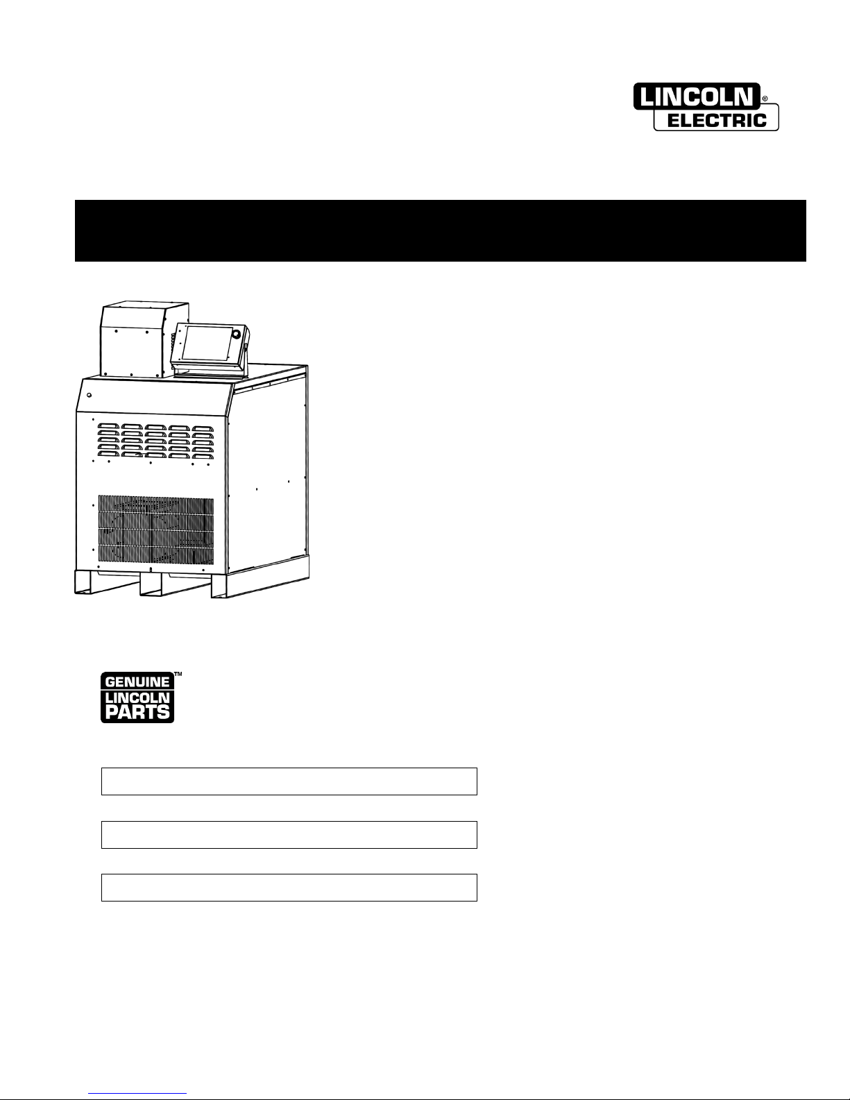
SPIRIT II 150
with FineLine High Definition Technology
Save for future reference
Date Purchased:
Model Number:
Serial Number:
BK718113 Rev I |
© Lincoln Global, Inc. All Rights Reserved Phone: +1.843.695.4000 www.lincolnelectric.com
This information is subject to the controls of the Export Administration Regulations [EAR]. This information shall not be provided to
non-U.S. persons or transferred by any means to any location outside the United States contrary to the requirements of the EAR.
Register your equipment:
http://www.burny.com/warranty
Issue Date: 01-SEP-2015 4130 Carolina Commerce Pkwy Ladson, SC 29456 U.S.A.
THE LINCOLN ELECTRIC COMPANY

Prologue Spirit II User’s Manual
Rev
ECO#
Author
Date
Description of Change
Added 100A/150A silver electrodes, replaced RHF with ISC,
added 100 psi minimum to inlet gas pressure.
Deionization filter cartridge (500510) replaced sediment filter
clarify cabling requirements for various configurations.
Corrected contact ratings on page 3-20.
ground in Parts List.
Inductor (707150) replaced by (707155). 10” fan (500516)
Control description.
Added “BK” prefix to all part numbers. Added PCB Outline
Remote On/Off info in Installation section.
Clarified fuse/breaker types in Installation section, updated
hot parts warning.
Changed ISC to ASC. Updated branding throughout.
Corrected gas flow rates on page 2-6.
LAD0234
LAD0330
Updated part numbers for terminal blocks. Updated AGC
(32mm) MS at 150A.
Revision History
A - CAD 02/04/2013 Initial Release.
B LAD0202 CAD 06/07/2013
C LAD0217 CAD 08/06/2013
D
E LAD0260 CAD 03/18/2014
F LAD0264 CAD 03/31/2014
G
LAD0228
LAD0223
LAD0276
LAD0199
LAD0284
LAD0288
CAD 08/28/2013
CAD 09/18/2014
added argon marking, corrected system interconnect
diagrams, changed rated inlet gas pressure to 115 psi,
(300152). Parts list updated.
Corrected Plasma Console icon description from hardware
error to warning message.
Expanded notes on System Interconnection diagrams to
Added pinouts to CII, FII, JII cables in Parts List.
Corrected part numbers for coolant/power leads and work
replaced by (284031). Added argon purity specification.
Added notes about torch handle vent hole. Updated
Chopper Test Procedure. Clarified RS422 Parameter
Dwgs and corrected electrode tool in Part List. Corrected
Parts List with second o-ring in Q-D Head on cathode
adapter, corrected several parts numbers in the Parts List,
updated interior drawings of ISC console throughout, added
H LAD0313 CAD 01/30/2015
I
LAD0317
LAD0323
CAD 09/01/2015
Trademark Notice
Spirit is a registered trademark of Lincoln Global, Inc.
FASTON is a trademark of the TE Connectivity Ltd family of companies.
All other trademarks are property of their respective owners.
This documentation may not be copied, photocopied, reproduced, translated, or
reduced to any electronic medium or machine-readable format without explicit
written permission from Lincoln Electric.
This information is subject to the controls of the Export Administration Regulations [EAR]. This information shall not be provided to
non-U.S. persons or transferred by any means to any location outside the United States contrary to the requirements of the EAR.
Combined RHF and CleanStrike™ Technology throughout.
and manifold part numbers. Updated coolant pump part
number. Updated warranty. Added pierce capability for 1.25”
ii

Spirit II User’s Manual Prologue
Table of Contents
Section 1: Safety
General Precautions ......................................................................................... 1-1
Ultraviolet Radiation Protection ......................................................................... 1-1
Noise Protection ................................................................................................ 1-1
Toxic Fume Prevention ..................................................................................... 1-2
Electric Shock Prevention ................................................................................. 1-2
Fire Prevention .................................................................................................. 1-3
Explosion Prevention......................................................................................... 1-3
Health Support Equipment ................................................................................ 1-4
Safety Standards Booklet Index ........................................................................ 1-5
Section 2: Specifications
System Description ........................................................................................... 2-1
System Components ......................................................................................... 2-2
Power Supply Specifications ............................................................................. 2-3
Torch Coolant Specifications ............................................................................. 2-4
Automatic Gas Console (AGC) Specifications .................................................. 2-5
Gas Supply Requirements ................................................................................ 2-6
Plasma Console Specifications ......................................................................... 2-7
Arc Starting Console (ASC) Specifications with RHF ........................................ 2-8
Arc Starting Console (ASC) Specifications with CleanStrike™ .......................... 2-9
Torch and 2-Gang Manifold Specifications ........................................................ 2-10
5-Gang Manifold Specifications ......................................................................... 2-11
Airborne Noise Emissions ................................................................................. 2-12
Electromagnetic Compatibility (EMC) ................................................................ 2-12
Section 3: Installation
Initial Inspection ................................................................................................ 3-1
Component Placement ...................................................................................... 3-1
System Interconnection ..................................................................................... 3-2
Power Supply Primary Power Connections ....................................................... 3-7
Power Supply Output Connections ................................................................... 3-9
ASC Control Cable and ASC Ground Connections ........................................... 3-11
Cooling System Connections ............................................................................ 3-11
Torch Leads to Arc Starting Console Connections ............................................ 3-13
Torch Leads to Torch Base Connections .......................................................... 3-15
Torch Gas Connections ..................................................................................... 3-16
Gas Supply Connections ................................................................................... 3-19
Plasma Console Connections ........................................................................... 3-20
CAN Communication Connections .................................................................... 3-21
CNC Machine Interface Connections ................................................................ 3-22
Filling the Cooling System ................................................................................. 3-23
This information is subject to the controls of the Export Administration Regulations [EAR]. This information shall not be provided to
non-U.S. persons or transferred by any means to any location outside the United States contrary to the requirements of the EAR.
iii

Prologue Spirit II User’s Manual
Section 4: Operation
Operating the Plasma Console ......................................................................... 4-1
Setting up to Cut or Mark .................................................................................. 4-3
Verifying Important Parameters ......................................................................... 4-4
Viewing the Required Torch Parts ..................................................................... 4-4
Checking System Status ................................................................................... 4-5
Purging Pressure Regulators ............................................................................ 4-6
Making a Cut or Mark ........................................................................................ 4-7
Piercing Thick Materials .................................................................................... 4-8
Moving Pierces and Edge Starts ....................................................................... 4-8
Cut Quality ........................................................................................................ 4-9
Customizing Cutting or Marking Settings .......................................................... 4-10
Saving Customized Settings ............................................................................. 4-11
Restoring or Deleting Customized Settings ....................................................... 4-12
Configuration Tab .............................................................................................. 4-13
Advanced Config Tab ........................................................................................ 4-14
Network Settings Tab ........................................................................................ 4-15
Software Updates Tab ....................................................................................... 4-16
System Info Tab ................................................................................................ 4-18
Tools Tab (Restart Plasma Console) ................................................................ 4-18
Pressures/Coolant Tab ...................................................................................... 4-19
RS422 Tab ........................................................................................................ 4-20
Electrical Tab .................................................................................................... 4-21
Cut Info Tab ...................................................................................................... 4-21
Power Supply Tab ............................................................................................. 4-23
Error Log Tab .................................................................................................... 4-23
Messages Tab ................................................................................................... 4-24
Section 5: Torch Consumables and Cutting Charts
Installing / Removing the Torch Head ............................................................... 5-1
Installing / Replacing Consumables .................................................................. 5-3
Maximizing Consumable Life ............................................................................ 5-5
Inspecting for Damage ...................................................................................... 5-6
Selecting Consumables ..................................................................................... 5-7
Cutting Charts ................................................................................................... 5-14
Section 6: Maintenance and Troubleshooting
Routine Maintenance ........................................................................................ 6-1
Replacing the Torch Coolant and Filter ............................................................. 6-4
Power Supply Microprocessor (DSP) Status Indicators .................................... 6-5
Power Supply Microprocessor (DSP) Sequence of Operation .......................... 6-5
Error Codes ....................................................................................................... 6-7
General Troubleshooting ................................................................................... 6-9
Chopper Test Procedure ................................................................................... 6-11
This information is subject to the controls of the Export Administration Regulations [EAR]. This information shall not be provided to
non-U.S. persons or transferred by any means to any location outside the United States contrary to the requirements of the EAR.
iv

Spirit II User’s Manual Prologue
Section 7: Parts List
Power Supply (BK300211 - BK300219) ............................................................ 7-1
Automatic Gas Console (BK300418)................................................................. 7-5
Plasma Console (BK300800) ............................................................................ 7-8
Arc Starting Console (BK300510) with RHF ...................................................... 7-9
Arc Starting Console (BK300500) with CleanStrike™ ........................................ 7-10
Torch and Manifold Assemblies ........................................................................ 7-11
Shielded Torch Leads ....................................................................................... 7-12
CAN Communication Cable and Termination Plug ........................................... 7-12
Manifold Control Cables .................................................................................... 7-12
Gas Hose Package with AGC ........................................................................... 7-13
Coolant and Power Leads ................................................................................. 7-14
Work Ground Lead ............................................................................................ 7-14
Oxygen Supply Gas Hose (Optional) ................................................................ 7-15
Nitrogen Supply Gas Hose (Optional) ............................................................... 7-15
Air Supply Gas Hose (Optional) ........................................................................ 7-15
H17 Supply Gas Hose (Optional) ...................................................................... 7-15
Argon Supply Gas Hose (Optional) ................................................................... 7-15
"CII" Cable (for Optional External Inova) ........................................................... 7-16
"FII" Cable (for Optional Internal Inova) ............................................................. 7-17
"JII" Cable (for Optional Internal Inova) ............................................................. 7-18
PCB Assemblies – Component Reference Locations ....................................... 7-19
Section 8: Internal Inova Console Option
Overview ........................................................................................................... 8-1
Plug Identification .............................................................................................. 8-1
Unique Interconnect Cables .............................................................................. 8-1
Grounding ......................................................................................................... 8-2
Parts List ........................................................................................................... 8-3
Appendix A: Electromagnetic Compatibility (EMC)
Background ....................................................................................................... A-1
Installation and Use ........................................................................................... A-1
Assessment of Area .......................................................................................... A-2
Methods of Reducing Emissions ....................................................................... A-2
Appendix B: Serial Communication
Initializing the Spirit System ............................................................................. B-1
Transmitting Parameters to the Spirit System ................................................... B-1
Communication Error Checking ....................................................................... B-2
Default Cutting Parameters .............................................................................. B-3
Troubleshooting Serial Communication ............................................................ B-3
RS-422 Serial Commands ................................................................................ B-4
This information is subject to the controls of the Export Administration Regulations [EAR]. This information shall not be provided to
non-U.S. persons or transferred by any means to any location outside the United States contrary to the requirements of the EAR.
v
RESPONSABILITÉ LIMITÉE
Garantie actuelle disponible à www.lincolnelectric.com/warranty
Burny Kaliburn, A Lincoln Electric Company (“Kaliburn”), warrants
DÉCLARATION DE RESPONSABILITÉ LIMITÉE
that all new Kaliburn-manufactured controllers and plasma
cutting equipment, torch height control systems, plasma torches,
Lincoln Electric Company (Lincoln) garantit à l’usager final (acheteur) de
consumables (expendables), and accessories (collectively, “Goods”)
tous les appareils de soudage et de coupage neufs, d’électrode et de flux
will be free of defects in workmanship and material, subject to the
(collectivement appelés « Biens ») qu’ils ne présenteront aucun défaut de
terms of this Limited Warranty.
fabrication et de matériel.
Cette garantie est annulée si l’appareil a été sujet à une mauvaise
WARRANTY REMEDY:
installation, à des soins inappropriés ou à des o
Purchaser must promptly report any defect or failure of the Goods
PÉRIODE DE GARANTIE
to Kaliburn, an authorized service center, or an authorized OEM/
Lincoln assurera les dépenses relatives aux pièces et à la main d’œuvre
integrator/distributor. Such notice must be in writing and received
pour la correction des défauts durant la période de garantie. Toute
within the warranty periods set forth herein. Upon receiving such
période de garantie commence à la date de l’achat, chez un Distributeur
written notice, and if Kaliburn or Kaliburn’s authorized service
Lincoln Agréé ou dans un Atelier de Service Agréé par Lincoln, par
facility confirms the existence of a defect covered by this warranty,
l’usager final d’origine, ou bien à partir de la da
Kaliburn will, at its sole option, repair or replace the defective Goods.
aucune preuve d’achat n’est disponible, le tout dans les conditions
At Kaliburn’s request, the purchaser must return to Kaliburn or its
suivantes :
authorized service facility any Goods claimed to be defective. Kaliburn
7 Ans
reserves the right to refuse to perform the warranty remedies set
• Redresseurs d’alimentation principale sur les soudeuses Idealarc®de type
forth herein if the Goods are not received by Kaliburn within sixty (60)
non-onduleur
days of the return request date. The purchaser is solely responsible
for shipment of any defective Goods to and from Kaliburn’s facility or
3 Ans
that of its authorized service facility and all related freight costs.
• Toutes les soudeuses, dévidoirs et machines pour couper le plasma de Lin-
coln.
• Casques auto-obscurcissants Viking™ désignés par les numéros de
WARRANTY PERIODS
référence de produits se terminant en "-2" (ex. KXXXX-2). Les e
All warranty periods start from the date of shipment from Kaliburn.
figurent dans la liste pour 2 Ans.
2 Ans
PARTS FOR:
• Casques auto-obscurissants, tous les autres casques Viking™ y compris
les casques de la série 1740 et les casques passifs 4x5.
• All Plasma Power Supplies, Gas Consoles, Cooling
Tower, Plasma Controllers for the Spirit® II series
1 An
• Handy MIG®, Handy Core®, Weld Pak™ HD
(as applicable), Spirit series
• Tous les refroidisseurs à eau (modèles internes ou externes)
(as applicable), ProLine® series (as applicable),
Dagger® 100 and other legacy plasma cutters
• Tous les régulateurs de gaz
• Toutes les baguettes d’électrode, fils à souder et flux (Contacter le
• Integrated INOVA™ electronics within the power
Représentant de Ventes
supply for Spirit II and ProLine series products
• Robots de soudage à l’arc et de coupage et contrôleurs robotiques
• Tous les appareils de Contrôle des Vapeurs de Soudage, y compris les ap-
PARTS FOR:
pareils portables, les unités centrales, les extincteurs et les accessoires
(Ne comprend pas les articles de matériel consommable figurant sur la
• All Burny® shape cutting controllers such as
liste d’articles ayant 30 jours de garantie)
product models for Phantom™, Phantom II,
• Tout les accessoires de soudage et de coupage, y
Phantom ST, Phantom ST II, Burny 10LCD Plus and
dévidoirs, les chariots, les options à installer sur le terrain qui sont vendues
Dagger NC and others as applicable
séparément, les options non fixées, les fournitures de soudage, les jeux
• All chassis and front panel upgrades (as applicable)
d’accessoires standards et les produits Magnum®(Ne comprend pas les
pièces consommables et les pistolets / torches figurant sur la liste d’arti-
• Dagger 100 torch and leads
cles ayant une garantie de 90 et 30 jours)
• All plasma cutting torches and torch leads for
• Toutes les torches TIG Pro-Torch™
Spirit II, Spirit, ProLine and other plasma cutters
s les torches de coupage au plasma
• Toute
• Toutes les pièces de rechange non consommables achetées
• All other plasma cutting system components such
• Les Pistolets à Bobine Magnum
as Arc Starting Consoles
• Les Pistolets à système pousser
• All torch height control systems and collision
• Mobiles VRTEX®360 et VRTEX
sensors
• Viking™ PAPR Blower Unit
• Poussoirs magnétiques main
• All purchased non-expendable replacement parts
90 Jours
• All torch valve assemblies
• Tous les ensembles de pistolet et câble et les pistolets à bobine Magnum
SG
LABOR
30 Jours
• All warranty labor for Plasma power supplies, gas
• Tous les articles consommables pouvant être utilisés avec les Systèmes de
consoles, cooling tower, and plasma controllers
Contrôle des Vapeurs de Soudage décrits plus haut. Ceci comprend les
for Spirit series (as applicable), Spirit II, and INOVA
tuyaux, les filtres, les courroies et les adaptateurs de tuyaux
electronics within the power supply for Spirit II
• Tous les logiciels
- applicable in U.S. only
• Pièces non consommables - Lincoln n’est responsable du changement
d’aucune pièce non consommable nécessaire du fait d’une usure normale.
SPARE PARTS (all repair parts) Ninety
(1) (2) (3) (4) (5) (6) (7) (8) (9)
Lincoln le plus proche)
®
LIMITED WARRANTY
pérations anormales.
te de fabrication si
xceptions
Three
(3) years
compris les modules de
One
(1) year
®
250LX
One (1) year
(90) days
WARRANTY LIMITATIONS
Période de Temps Non Spécifiée
The Goods are intended for commercial use only and are not intended
• Les produits d’habillement Red Line™ sont garantis contre les défauts de
for personal, family, or household purposes.
fabrication. Du fait que les applications varient, il relève de la responsabil-
ité de l’usager de sélectionner le bon produit pour chaque application. Les
Kaliburn is not responsible for cable or torch leads wear or any
produits d’habillement Red Line™ ne sont pas sujets à la garantie après
damage resulting from cable wear due to flexing and abrasion.
usage.
Purchaser is solely responsible for routine inspection of cables.
• Les produits de la gamme de lunettes de sécurité Red Line™ sont garantis
Kaliburn is not responsible for repair or replacement of any part or
contre les défauts de fabrication
Goods due to normal wear and tear.
CONDITIONS DE GARANTIE À OBTENIR
COUVERTURE DE LA GARANTIE :
Parts and equipment manufactured for Kaliburn is subject to the
terms of the original manufacturer’s warranty, and Kaliburn has no
L’acheteu
Pour une assistance à la recherche d’un LASF, aller sur
r doit contacter un Atelier de Service Agréé par Lincoln (LASF).
warranty obligations for defect in such equipment.
22801 St. Clair Avenue • Cleveland, OH • 44117-1199 • U.S.A.
THE LINCOLN ELECTRIC COMPANY
Phone: +1.888.935.3877 • www.lincolnelectric.com
www.lincolnelectric.com/locator
THIS WARRANTY IS VOID IF:
La détermination finale de la garantie sur les produits de soudage et de
coupage sera faite par Lincoln ou par l’Atelier de Service Agréé par
A. THE GOODS HAVE BEEN ABUSED, ALTERED, OR MISUSED;
Lincoln.
B. THE GOODS HAVE BEEN REPAIRED BY THE PURCHASER OR
RÉPARATIONS COUVERTES PAR LA GARANTIE :
ANY THIRD PARTY WITHOUT THE AUTHORIZATION OR PRIOR
WRITTEN APPROVAL OF KALIBURN;
Si Lincoln ou l’Atelier de Service Agréé par Lincoln confirm
d’un défaut couvert par cette garantie, celui-ci sera corrigé par
C. THE SPIRIT II, SPIRIT OR PROLINE SYSTEM HAS BEEN OPERATED
réparation ou par changement, au choix de Lincoln.
WITH NON-GENUINE KALIBURN OR LINCOLN ELECTRIC TORCH
CONSUMABLES;
À la demande de Lincoln, l’acheteur doit rendre, à Lincoln ou à son Atelier
de Service Agréé, tout « Bien » réclamé comme défectueux couvert par la
D. KALIBURN SERIAL NUMBERS OR WARRANTY DECALS HAVE
garantie de Lincoln.
BEEN REMOVED OR ALTERED; OR
FRAIS DE PORT :
E. THE GOODS HAVE BEEN SUBJECTED TO IMPROPER
L’acheteur est responsable de l’expédition vers et depuis l’Atelier de
INSTALLATION, IMPROPER CARE, UNAPPROVED PURPOSES, OR
Service Agréé par L
ABNORMAL OPERATIONS.
LIMITES DE LA GARANTIE:
SERVICE AND REPAIR SHOULD ONLY BE PERFORMED BY KALIBURN
LINCOLN N’ACCEPTERA AUCUNE RESPONSABILITÉ DANS LE CAS DE RÉPARATIONS
FACTORY TRAINED PERSONNEL. UNAUTHORIZED REPAIRS
EFFECTUÉES HORS D’UN ATELIER DE SERVICE AGRÉÉ PAR LINCOLN.
PERFORMED ON THIS EQUIPMENT MAY RESULT IN DANGER TO THE
LA RESPONSABILITÉ DE LINCOLN SELON CETTE GARANTIE NE DÉPASSERA PAS LE
TECHNICIAN AND MACHINE OPERATOR AND WILL INVALIDATE YOUR
COÛT DE LA CORRECTION DU DÉFAUT DU PRODUIT DE LINCOLN.
FACTORY WARRANTY.
LINCOLN NE SERA PAS RESPONSABLE DES DOMMAGES ACCIDENTELS OU
THE EXPRESS LIMITED WARRANTIES SET FORTH HEREIN ARE THE
CONSÉQUENTS (TELS QUE LA PERTE D’AFFAIRES COMMERCIALES, ETC.) CAUSÉS
SOLE AND EXCLUSIVE WARRANTIES FOR THE GOODS. ALL OTHER
PAR LE DÉFAUT OU PAR LE TEMPS NÉCESSAIRE À LA CORRECTION DU DÉFAUT.
WARRANTIES, WHETHER EXPRESS, IMPLIED, OR STATUTORY,
CETTE GARANTIE ÉCRITE EST LA SEULE GARANTIE EXPRESSE FOURNIE PAR
INCLUDING BUT NOT LIMITED TO THOSE OF MERCHANTABILITY,
LINCOLN CONCERNANT SES PRODUITS. LES GARANTIES IMPLIQUÉES PAR LA LOI,
FITNESS FOR A PARTICULAR PURPOSE, OR NON-INFRINGEMENT,
TELLES QUE LA GARANTIE DE QUALITÉ MARCHANDE, SE LIMITENT À LA DURÉE DE
ARE EXPRESSLY DISCLAIMED.
CETTE GARANTIE LIMITÉE POUR L’APPAREIL EN QUESTION.
KALIBURN’S LIABILITY UNDER THIS WARRANTY SHALL
CETTE GARANTIE DONNE À L’ACHETEUR DES DROITS LÉGAUX SPÉCIFIQUES.
NOT EXCEED THE COST OF REPAIRING OR REPLACING THE
L’ACHETEU
D’UN ÉTAT À L’AUTRE.
(1) Les appareils fabriqués pour The Lincoln Electric Company sont sujets à
(2) Tous les moteurs et accessoires pour moteurs sont garantis par le fabri-
(3) Les compresseurs AIR VANTAGE
(4) Tous les Produits MK sont garantis par MK Products et ne sont pas cou-
(5) Lincoln Electric n’est pas responsable de l’usure des câbles ni des dom-
®
(6) Tous les Produits Burny Kaliburn sont garantis par Burny Kaliburn et ne
(7) Tous les Produits Vernon Tools sont garantis par Vernon Tool et ne sont
(8) Tous les Produits Arc Products sont garantis par Arc Products et ne sont
(8) Tous les Produits ELCo Enterprises, Inc sont garantis par ELCo Enter-
R PEUT ÉGALEMENT AVOIR D’AUTRES DROITS QUI PEUVENT VARIER
DEFECTIVE GOODS.
IN NO EVENT, WHETHER IN CONTRACT, TORT OR OTHERWISE
la période de garantie du fabricant original.
(INCLUDING BREACH OF WARRANTY, NEGLIGENCE AND STRICT
LIABILITY IN TORT), WILL KALIBURN BE LIABLE FOR INDIRECT,
cant du moteur ou des accessoires pour moteurs et ils ne sont pas cou-
EXEMPLARY, PUNITIVE, SPECIAL, OR CONSEQUENTIAL DAMAGES
verts par cette garantie.
(INCLUDING BUT NOT LIMITED TO LOSS OF BUSINESS OR LOST
PROFITS), EVEN IF KALIBURN HAS BEEN ADVISED OF THE
compresseur et ne sont pas couverts par cette garantie.
POSSIBILITY OF SUCH DAMAGES IN ADVANCE AND EVEN IF A
REMEDY SET FORTH HEREIN IS FOUND TO HAVE FAILED OF ITS
verts par cette garantie. Contacter le 1-800-787-9707.
ESSENTIAL PURPOSE.
mages résultant de l’usure des câbles suite à des courbures et à l’abra-
sion. L’usager final est respons
pour vérifier qu’ils ne présentent pas d’usure éventuelle et pour y remédier
avant la panne du câble.
sont pas couverts par cette garantie.
Email: burnykaliburntech@lincolnelectric.com.
pas couverts par cette g
www.vernontool.com/sales/product-warranty
pas couverts par cette garantie.
Email: service@arc-products.com
prises, Inc et ne sont pas couverts par cette garantie.
Contacter le (517) 782-8040
incoln.
®
500 sont garantis par le fabricant du
able de l’inspection de routine des câbles
arantie.
4130 Carolina Commerce Parkway, Ladson, SC 29456
Phone: +1.843.695.4000 | www.lincolnelectric.com
The Lincoln Electric Company
e l’existence
Mar 14

Spirit II User’s Manual Section 1: Safety
This information is subject to the controls of the Export Administration Regulations [EAR]. This information shall not be provided to
non-U.S. persons or transferred by any means to any location outside the United States contrary to the requirements of the EAR.
1-1
Section 1: Safety
General Precautions
Whereas plasma cutting has been used safely for years, it does require certain
precautions to ensure the safety of the operator and other people around the
equipment. The following safety information must be provided to each person who will
operate, observe, perform maintenance, or work in close proximity to this piece of
equipment. Always wear appropriate personal protective equipment (PPE).
Installation, operation, and repairs made to the Spirit system should only be performed
by qualified personnel. The system makes use of both A.C. and D.C. circuitry for
operation. Fatal shock hazard does exist. Exercise extreme caution while working
on the system.
Ultraviolet Radiation Protection
Plasma cutting produces ultraviolet radiation similar to a welding arc. This ultraviolet
radiation can cause skin and eye burns. For this reason, it is essential that proper
protection be worn. The eyes are best protected by using safety glasses or a welding
helmet with an AWS No. 12 shade or ISO 4850 No. 13 shade, which provides protection
up to 400 amperes. All exposed skin areas should be covered with flame-retardant
clothing. The cutting area should also be prepared in such a way that ultraviolet light
does not reflect. Walls and other surfaces should be painted with dark colors to reduce
reflected light. Protective screens or curtains should be installed to protect additional
workers in the area from ultraviolet radiation.
Noise Protection
The system generates high noise levels while cutting. Depending on the size of the
cutting area, distance from the cutting torch, and arc current cutting level, acceptable
noise levels may be exceeded. Proper ear protection should be used as defined by
local or national codes. See Section 2 for noise emission levels.

Section 1: Safety Spirit II User’s Manual
This information is subject to the controls of the Export Administration Regulations [EAR]. This information shall not be provided to
non-U.S. persons or transferred by any means to any location outside the United States contrary to the requirements of the EAR.
1-2
Toxic Fume Prevention
Care should be taken to ensure adequate ventilation in the cutting area. Some
materials give off toxic fumes that can be harmful or fatal to people in the vicinity of the
cutting area. Also, some solvents decompose and form harmful gases when exposed
to ultraviolet radiation. These solvents should be removed from the area prior to cutting.
Galvanized metal can produce harmful gases during the cutting process. Ensure proper
ventilation and use breathing equipment when cutting these materials.
Certain metals coated with or containing lead, cadmium, zinc, beryllium, and mercury
produce harmful toxins. Do not cut these metals unless all people subjected to the
fumes wear proper air breathing equipment.
Electric Shock Prevention
The Spirit system uses high open circuit voltages that can be fatal. Extreme care
should be used when operating or performing maintenance on the system. Only
qualified personnel should service the system. Observe the following guidelines to
protect against electric shock:
• A wall-mounted disconnect switch should be installed and fused according to local
and national electrical codes. The disconnect switch should be located as close as
possible to the power supply so it can be turned off in case of an emergency.
• The primary power cord should have a 600 volt minimum rating in order to protect
the operator. In addition, it should be sized according to local and national electrical
codes. Inspect the primary power cord frequently. Never operate the system if the
power cord is damaged in any way.
• Make sure the primary power ground wire is connected to the input power ground
stud on the power supply. Make sure the connection is securely tightened.
• Make sure the positive output (work ground) of the power supply is connected to a
bare metal area on the cutting table. A driven ground rod should be placed no
further than five feet from this connection. Make sure this ground point on the
cutting table is used as the star ground point for all other ground connections.
• Inspect the torch leads frequently. Never use the system if the leads are damaged
in any way.
• Do not stand in wet, damp areas when operating or performing maintenance on the
system.
• Wear insulated gloves and shoes while operating or performing maintenance on the
system.
• Make sure the system is switched off at the wall disconnect before servicing the
power supply or torch.

Spirit II User’s Manual Section 1: Safety
This information is subject to the controls of the Export Administration Regulations [EAR]. This information shall not be provided to
non-U.S. persons or transferred by any means to any location outside the United States contrary to the requirements of the EAR.
1-3
• Never change torch consumable parts unless the system is switched off at the wall
disconnect.
• Do not attempt to remove any parts from beneath the torch when cutting.
Remember that the workpiece forms the current path back to the power supply.
• Never bypass the safety interlock devices.
• Before removing any of the covers, switch the system off at the wall disconnect.
Wait at least five (5) minutes before removing any cover. This will give the
capacitors inside the unit time to discharge. See Section 6 for additional safety
precautions.
• Never operate the system without all of the covers in place. See Section 6 for
additional safety precautions.
• Preventive maintenance should be performed daily to avoid possible safety hazards.
Fire Prevention
When using the Spirit system, it is necessary to exercise good judgment. While cutting,
the arc produces sparks that could cause a fire if they fall on flammable materials.
Make sure that all flammable materials are a suitable distance away from the cutting
area. All flammable liquids should be at least 40 feet away from the cutting area,
preferably stored in a metal cabinet. Plasma cutting should never be attempted on
containers that contain flammable materials. Make sure that fire extinguishers are
readily accessible in the cutting area.
Make sure that the cutting area is properly ventilated when using oxygen as a cutting
gas.
Explosion Prevention
The Spirit system uses compressed gases. Use proper techniques when handling
compressed gas cylinders and other compressed gas equipment. Observe the
following guidelines to protect against explosion:
• Never operate the system in the presence of explosive gases or other explosive
materials.
• Never cut pressurized cylinders or any closed container.
• When using a water table and cutting aluminum under water or with water touching
the underside of the aluminum plate, hydrogen gas is produced. This hydrogen gas
may collect under the plate and explode during the cutting process. Make sure the
water table is properly aerated to help prevent the accumulation of hydrogen gas.
• Handle all gas cylinders in accordance with safety standards published by the U.S.
Compressed Gas Association (CGA), American Welding Society (AWS), Canadian
Standards Association (CSA), or other local or national codes.

Section 1: Safety Spirit II User’s Manual
This information is subject to the controls of the Export Administration Regulations [EAR]. This information shall not be provided to
non-U.S. persons or transferred by any means to any location outside the United States contrary to the requirements of the EAR.
1-4
• Compressed gas cylinders should be maintained properly. Never attempt to use a
cylinder that is leaking, cracked, or has other signs of physical damage.
• All gas cylinders should be secured to a wall or rack to prevent accidental knock
over.
• If a compressed gas cylinder is not being used, replace the protective valve cover.
• Never attempt to repair compressed gas cylinders.
• Keep compressed gas cylinders away from intense heat, sparks, or flames.
• Clear the compressed gas cylinder connection point by opening the valve
momentarily prior to installing a regulator.
• Never lubricate compressed gas cylinder valves or pressure regulators with any type
of oil or grease.
• Never use a compressed gas cylinder or pressure regulator for any purpose other
than which it is intended.
• Never use a pressure regulator for any gas other than which it is intended.
• Never use a pressure regulator that is leaking or has other signs of physical
damage.
• Never use oxygen hoses and pressure regulators for any gas other than oxygen.
• Never use any gas hose that is leaking or has other signs of physical damage.
Health Support Equipment
The Spirit system creates electric and magnetic fields that may interfere with certain
types of health support equipment, such as pacemakers. Any person who uses a
pacemaker or similar item should consult a doctor before operating, observing,
maintaining, or servicing the system. Observe the following guidelines to minimize
exposure to these electric and magnetic fields:
• Stay as far away from the power supply, torch, torch leads, and arc starting console
as possible.
• Route the torch leads as close as possible to the work ground cable.
• Never place your body between the torch leads and work ground cable. Keep the
work ground cable and the torch leads on the same side of your body.
• Never stand in the center of a coiled up set of torch leads or work ground cable.

Spirit II User’s Manual Section 1: Safety
This information is subject to the controls of the Export Administration Regulations [EAR]. This information shall not be provided to
non-U.S. persons or transferred by any means to any location outside the United States contrary to the requirements of the EAR.
1-5
Safety Standards Booklet Index
For further information concerning safety practices to be exercised with plasma arc
cutting equipment, please refer to the following publications:
1. AWS Standard AWN, Arc Welding and Cutting Noise, obtainable from the American
Welding Society, 550 NW LeJeune Road, Miami, FL 33126.
2. AWS Standard C5.2, Recommended Practices for Plasma Arc Cutting, obtainable
from the American Welding Society, 550 NW LeJeune Road, Miami, FL 33126.
3. AWS Standard FSW, Fire Safety in Welding and Cutting, obtainable from the
American Welding Society, 550 NW LeJeune Road, Miami, FL 33126.
4. AWS Standard F4.1, Recommended Safe Practices for Preparation for Welding and
Cutting of Containers and Piping, obtainable from the American Welding Society,
550 NW LeJeune Road, Miami, FL 33126.
5. AWS Standard ULR, Ultraviolet Reflectance of Paint, obtainable from the American
Welding Society, 550 NW LeJeune Road, Miami, FL 33126.
6. AWS / ANSI Standard Z49.1, Safety in Welding, Cutting, and Allied Processes,
obtainable from the American Welding Society, 550 NW LeJeune Road, Miami, FL
33126.
7. ANSI Standard Z41.1, Standard For Men’s Safety-Toe Footwear, obtainable from
the American National Standards Institute, 11 West 42nd Street, New York, NY
10036.
8. ANSI Standard Z49.2, Fire Prevention in the Use of Cutting and Welding
Processes, obtainable from the American National Standards Institute, 11 West
42nd Street, New York, NY 10036.
9. ANSI Standard Z87.1, Safe Practices For Occupation and Educational Eye and
Face Protection, obtainable from the American National Standards Institute, 11
West 42nd Street, New York, NY 10036.
10. ANSI Standard Z88.2, Respiratory Protection, obtainable from the American
National Standards Institute, 11 West 42nd Street, New York, NY 10036.
11. OSHA Standard 29CFR 1910.252, Safety and Health Standards, obtainable from
the U.S. Government Printing Office, Washington, D.C. 20402.

Section 1: Safety Spirit II User’s Manual
This information is subject to the controls of the Export Administration Regulations [EAR]. This information shall not be provided to
non-U.S. persons or transferred by any means to any location outside the United States contrary to the requirements of the EAR.
1-6
12. NFPA Standard 51, Oxygen - Fuel Gas Systems for Welding, Cutting, and Allied
Processes, obtainable from the National Fire Protection Association, 1
Batterymarch Park, Quincy, MA 02269.
13. NFPA Standard 51B, Cutting and Welding Processes, obtainable from the National
Fire Protection Association, 1 Batterymarch Park, Quincy, MA 02269.
14. NFPA Standard 70, National Electrical Code, obtainable from the National Fire
Protection Association, 1 Batterymarch Park, Quincy, MA 02269.
15. CGA booklet P-1, Safe Handling of Compressed Gases in Containers, obtainable
from the Compressed Gas Association, 1725 Jefferson Davis Highway, Suite 1004,
Arlington, VA 22202.
16. CGA booklet P-14, Accident Prevention in Oxygen-Rich and Oxygen-Deficient
Atmospheres, obtainable from the Compressed Gas Association, 1725 Jefferson
Davis Highway, Suite 1004, Arlington, VA 22202.
17. CGA booklet TB-3, Hose Line Flashback Arrestors, obtainable from the
Compressed Gas Association, 1725 Jefferson Davis Highway, Suite 1004,
Arlington, VA 22202.
18. CSA Standard W117.2, Safety in Welding, Cutting, and Allied Processes,
obtainable from Canadian Standards Association, 178 Rexdale Boulevard, Toronto,
Ontario M9W lR3, Canada.
19. Canadian Electrical Code Part 1, Safety Standard for Electrical Installations,
obtainable from the Canadian Standards Association, 178 Rexdale Boulevard,
Toronto, Ontario M9W 1R3, Canada.

Spirit II User’s Manual Section 2: Specifications
This information is subject to the controls of the Export Administration Regulations [EAR]. This information shall not be provided to
non-U.S. persons or transferred by any means to any location outside the United States contrary to the requirements of the EAR.
2-1
Section 2: Specifications
System Description
The Spirit II 150 is a 150 amp microprocessor controlled, 100% duty cycle high current
density plasma cutting and marking system. It utilizes a precision, dual gas torch that is
capable of cutting mild steel up to 1-1/2" thick and stainless steel up to 1” thick.
The system contains a computer controlled automatic gas console with a touch screen
interface (plasma console). All cutting parameters are controlled through the plasma
console. Setting up a cut is as simple as selecting the material type, material thickness,
and process (cutting or marking). All gas types and pressures are set automatically.
The operator can easily view pictures and part numbers of the torch consumables.
Another screen shows the recommended cutting speed and torch height for making the
cut. These parameters can be transmitted to an X/Y machine controller or an arc
voltage control system via RS-422 serial communication. The RS-422 port also allows
for full control of the cutting parameters from an x/y machine controller. The system
keeps a detailed record of errors that may have occurred during the cutting sequence.
Additionally, systems utilizing the automatic gas console can use argon for marking,
which produces improved mark quality.
The Spirit II system is available with an Arc Starting Console (ASC) that utilizes
CleanStrike™ technology, which results in reduced EMI and thereby minimizes
interference with sensitive electronic equipment.
For cutting mild steel, the system uses oxygen for the plasma gas and either oxygen or
air for the shielding gas. When cutting stainless steel or other non-ferrous materials, air
or H17 (17.5% hydrogen, 32.5% argon, 50% nitrogen) is used for the plasma gas and
either air or nitrogen is used for the shielding gas. Oxygen and nitrogen are used for
the preflow and postflow gases.
The torch is water-cooled and consumables are machined to exacting dimensions and
checked with the latest computerized measuring systems. Five nozzle sizes (30, 50,
70, 100, and 150 amps) are available to produce excellent cut quality throughout the
cutting range.
Each enclosure in the system is rated for IP21S sealing, which is intended for
indoor use only. The system is not suitable for use in rain or snow.
Systems containing an ASC with CleanStrike™ Technology are only
recommended for use with downdraft cutting tables.

Section 2: Specifications Spirit II User’s Manual
This information is subject to the controls of the Export Administration Regulations [EAR]. This information shall not be provided to
non-U.S. persons or transferred by any means to any location outside the United States contrary to the requirements of the EAR.
2-2
System Components
The Spirit II 150 System consists of the following components:
Standard Components
• Power Supply
• Automatic Gas Console
• Plasma Console (Touch Screen)
• CAN Cables
• CAN Termination Plug
• Arc Starting Console (ASC) with Remote High Frequency (RHF)
- or -
Arc Starting Console (ASC) with CleanStrike™ Technology
• ASC Control Cable
• ASC Ground Cable
• Torch and Handle Assembly
• Torch Lead Set
• 5-gang Manifold Assembly
• 5-gang Manifold Control Cable
• 2-gang Manifold Assembly
• 2-gang Manifold Control Cable
• 17 Inch Plasma Hose
• Coolant and Power Leads
• Gas Hose Package
• Work Ground Lead
• Spirit II User’s Manual
Optional Components
• Supply Gas Hoses
• Internal Inova Console

Spirit II User’s Manual Section 2: Specifications
This information is subject to the controls of the Export Administration Regulations [EAR]. This information shall not be provided to
non-U.S. persons or transferred by any means to any location outside the United States contrary to the requirements of the EAR.
2-3
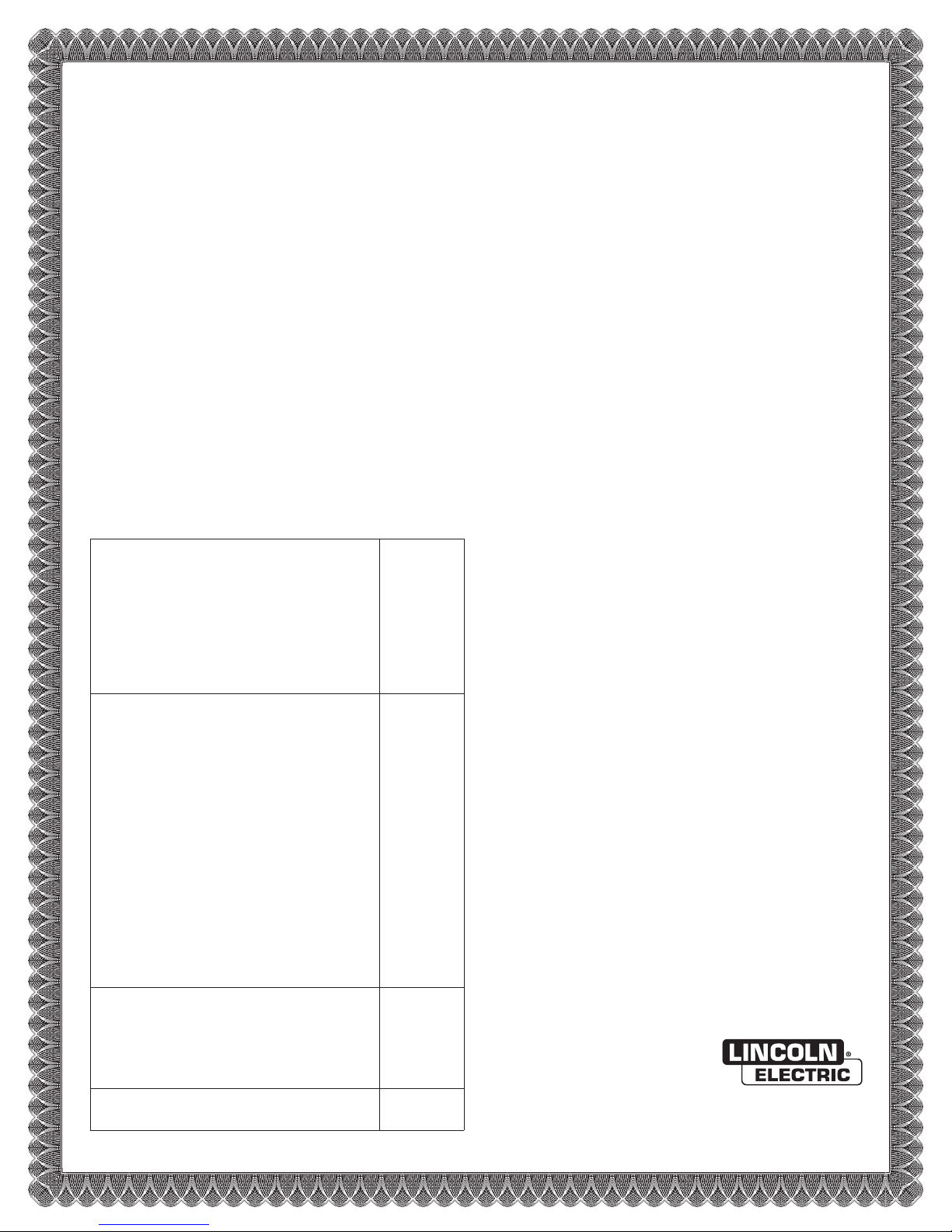
Power Supply Specifications
Power Supply Description Part Number
Input Current at
Maximum Output
208 VAC, 3Ø, 60Hz
BK300211
99 amps
220 VAC, 3Ø, 60Hz
BK300212
94 amps
240 VAC, 3Ø, 60Hz
BK300213
86 amps
380 VAC, 3Ø, 50/60Hz
BK300214
54 amps
400 VAC, 3Ø, 50/60Hz
BK300215
52 amps
415 VAC, 3Ø, 50/60Hz
BK300216
50 amps
440 VAC, 3Ø, 50/60Hz
BK300217
47 amps
480 VAC, 3Ø, 60Hz
BK300218
43 amps
600 VAC, 3Ø, 60Hz
BK300219
34 amps
Open Circuit Voltage ......................................... 300 VDC
Output Current (drooping characteristic) ........... 10 - 150 amps
Maximum Output Voltage ................................. 170 VDC
Duty Cycle ........................................................ 100% @ 25.5 kW
Maximum Ambient Temperature ....................... 104° F (40° C)
Coolant Discharge Pressure ............................. 150 psi (10.2 bar)
Coolant Flow Rate ............................................ 1 gal/min (3.8 liters/min)
Coolant Fluid ..................................................... Propylene glycol solution
Coolant Tank Capacity ...................................... 3.2 gal (12 liters)
Weight (without coolant) ................................... 953 lbs (432 kg)
38.4"
[975]
29.0" [737]
43.2" [1097]

Section 2: Specifications Spirit II User’s Manual
This information is subject to the controls of the Export Administration Regulations [EAR]. This information shall not be provided to
non-U.S. persons or transferred by any means to any location outside the United States contrary to the requirements of the EAR.
2-4
Torch Coolant Specifications
Note: Refer to the supplier’s most current Material Safety Data Sheet for
information regarding safety, handling, and storage of torch coolant.
The Spirit system is shipped without torch coolant in the reservoir. Coolant
must be added before applying power to the system. Only use approved
torch coolant solution for optimal system performance as commercially available
antifreeze contains corrosion inhibitors that will damage the cooling system. The
standard coolant solution consists of 25% industrial grade propylene glycol and
provides freezing protection down to -13º C (9º F). The standard solution can be
ordered in one-gallon containers, PN BK500695. For operating temperatures
below -13º C, a 50% solution of industrial grade propylene glycol can be ordered
in one-gallon containers, PN BK500895, providing protection down to -36º C
(-33º F).
Failure to use the proper propylene glycol solution may result in cooling
system and/or torch damage.
The torch coolant should be flushed out of the Spirit system every six months
and replaced with new coolant. The coolant filter / deionization cartridge should
also be changed at the same time. See Section 6 for details.
Spirit II User’s Manual Section 2: Specifications
This information is subject to the controls of the Export Administration Regulations [EAR]. This information shall not be provided to
non-U.S. persons or transferred by any means to any location outside the United States contrary to the requirements of the EAR.
2-5
Automatic Gas Console (AGC) Specifications
Part Number ..................................................... BK300418
Weight .............................................................. 53 lbs (24 kg)
12.4" [315]
12.0" [305]
13.7" [348]
10.9" [277]
7.0" [178]
(4) Ø .300 [7.6]

Section 2: Specifications Spirit II User’s Manual
This information is subject to the controls of the Export Administration Regulations [EAR]. This information shall not be provided to
non-U.S. persons or transferred by any means to any location outside the United States contrary to the requirements of the EAR.
2-6
Gas Supply Requirements
Plasma gas types:
Mild Steel ..................................................... Oxygen
Stainless Steel ............................................ Air or H17
Aluminum .................................................... Air
Shield gas types:
Mild Steel ..................................................... Oxygen or Air
Stainless Steel ............................................. Air or Nitrogen
Aluminum .................................................... Nitrogen
Preflow gas type ............................................... Oxygen and Nitrogen
Marking gas type............................................... Nitrogen or Argon
Plasma gas flow rate (maximum):
Oxygen or Air ............................................... 30 scfh (850 liters/hour)
H17 .............................................................. 56 scfh (1586 liters/hour)
Shield gas flow rate (maximum):
Oxygen ........................................................ 19 scfh (538 liters/hour)
Air or Nitrogen ............................................. 175 scfh (4955 liters/hour)
Preflow gas flow rate (maximum) ...................... 26 scfh (736 liters/hour)
Marking gas flow rate (maximum) ..................... 30 scfh (850 liters/hour)
Rated Inlet gas pressure ................................... 115 psi (7.9 bar)
Minimum Inlet gas pressure .............................. 110 psi (7.6 bar)
Maximum Inlet gas pressure ............................. 145 psi (10.0 bar)
Oxygen and nitrogen should be supplied with a purity of at least 99.5%. H17 purity
should be at least 99.995%. Argon purity should be at least 99.99%. All should be
clean, dry and oil-free.
A potential fire hazard exists when cutting with oxygen. It is recommended that
an exhaust ventilation system be used when cutting with oxygen. Flashback
arrestors must be supplied (unless they are not available for the chosen gases
and pressures) to prevent a possible fire from propagating back to the gas
supplies.
Ensure that oxygen lines remain free from contaminants such as oil and grease. The
mixture of such contaminants with oxygen presents an additional fire hazard.
Compressed air must be clean, dry, and oil-free and may be supplied from compressed
cylinders or from an air compressor. Be aware that shop air systems are prone to oil
and moisture contamination. If shop air is used, it must be cleaned to ISO 8573.1:
Class 1.4.1. Specify dry air when using compressed cylinders. Breathing quality air
contains moisture and must not be used.
3/8” (inside diameter) hoses are required for all inlet gas connections. Mating
connectors are supplied with the unit. Quick-connect fittings must not be used.
Spirit II User’s Manual Section 2: Specifications
This information is subject to the controls of the Export Administration Regulations [EAR]. This information shall not be provided to
non-U.S. persons or transferred by any means to any location outside the United States contrary to the requirements of the EAR.
2-7
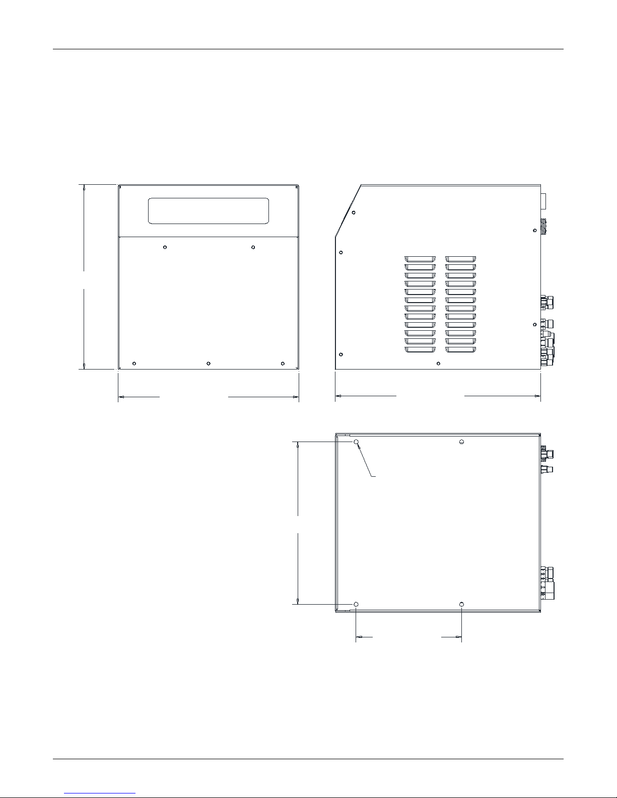
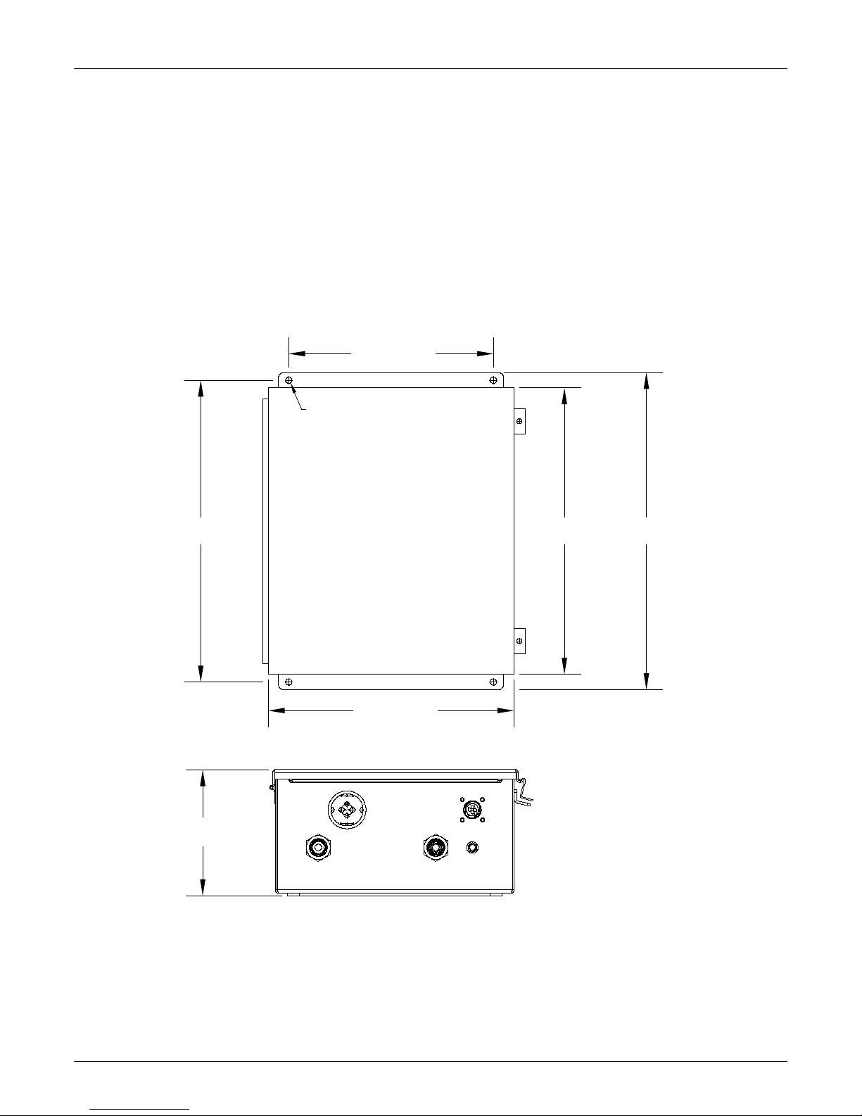
Plasma Console Specifications
Part Number ..................................................... BK300800
Weight .............................................................. 10 lbs (4.5 kg)
9.2" [234]
13.4" [340]
3.6" [91]
3.2" [81]
10.1" [257]
(4) Ø.180 [5]

Section 2: Specifications Spirit II User’s Manual
This information is subject to the controls of the Export Administration Regulations [EAR]. This information shall not be provided to
non-U.S. persons or transferred by any means to any location outside the United States contrary to the requirements of the EAR.
2-8
Arc Starting Console (ASC) Specifications
with Remote High Frequency (RHF)
Part Number .................................................... BK300510
Weight ............................................................... 24 lbs (10.9 kg)
Spark gap distance .......................................... 0.015 in (0.381 mm)
Note: The Spirit II system requires either an ASC with RHF or an ASC with
CleanStrike™ Technology, but not both.
12.75" [324]
8.00" [203]
12.00" [305]
13.50" [343]
10.00" [254]
5.35" [136]
(4) Ø.312 [8]
Spirit II User’s Manual Section 2: Specifications
This information is subject to the controls of the Export Administration Regulations [EAR]. This information shall not be provided to
non-U.S. persons or transferred by any means to any location outside the United States contrary to the requirements of the EAR.
2-9
Arc Starting Console (ASC) Specifications
with CleanStrike
™
Technology
Part Number .................................................... BK300500
Weight ............................................................... 22 lbs (10 kg)
Note: The Spirit II system requires either an ASC with RHF or an ASC with
CleanStrike™ Technology, but not both. Systems containing an ASC with CleanStrike™
Technology are only recommended for use with downdraft cutting tables.
12.75" [324]
8.00" [203]
12.00" [305]
13.50" [343]
10.00" [254]
5.35" [136]
(4) Ø.312 [8]
Section 2: Specifications Spirit II User’s Manual
This information is subject to the controls of the Export Administration Regulations [EAR]. This information shall not be provided to
non-U.S. persons or transferred by any means to any location outside the United States contrary to the requirements of the EAR.
2-10
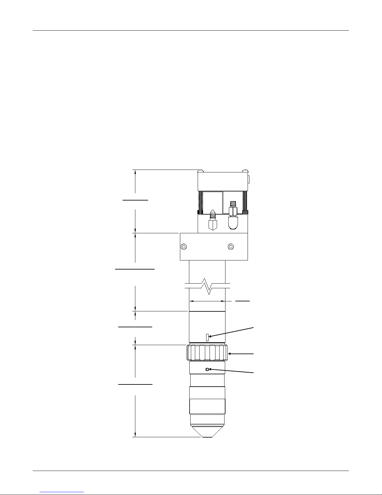
Torch and 2-Gang Manifold Specifications
Part Number:
2-Gang Manifold Assembly .................................................. BK284214
Torch Handle (standard) ...................................................... BK278001
Torch Handle (short) ............................................................ BK278018
Torch Base........................................................................... BK279000
Torch Head (Copper Electrode) ........................................... BK279100
Torch Head (Silver Electrode) .............................................. BK279060
Max Weight:
Manifold/Bracket, Handle (BK278001), Base and Head ...... 8.3 lbs (3.8 kg)
Torch Head
5.08" [129]
Torch Base
1.87" [47]
Torch Handle
BK278001 = 9.46" [240]
BK278018 = 7.06" [179]
1.99"
[51]
Alignment Indicator
(Slot)
Alignment Indicator
(Circle)
Attachment Ring
Manifold
3.38" [86]
Spirit II User’s Manual Section 2: Specifications
This information is subject to the controls of the Export Administration Regulations [EAR]. This information shall not be provided to
non-U.S. persons or transferred by any means to any location outside the United States contrary to the requirements of the EAR.
2-11
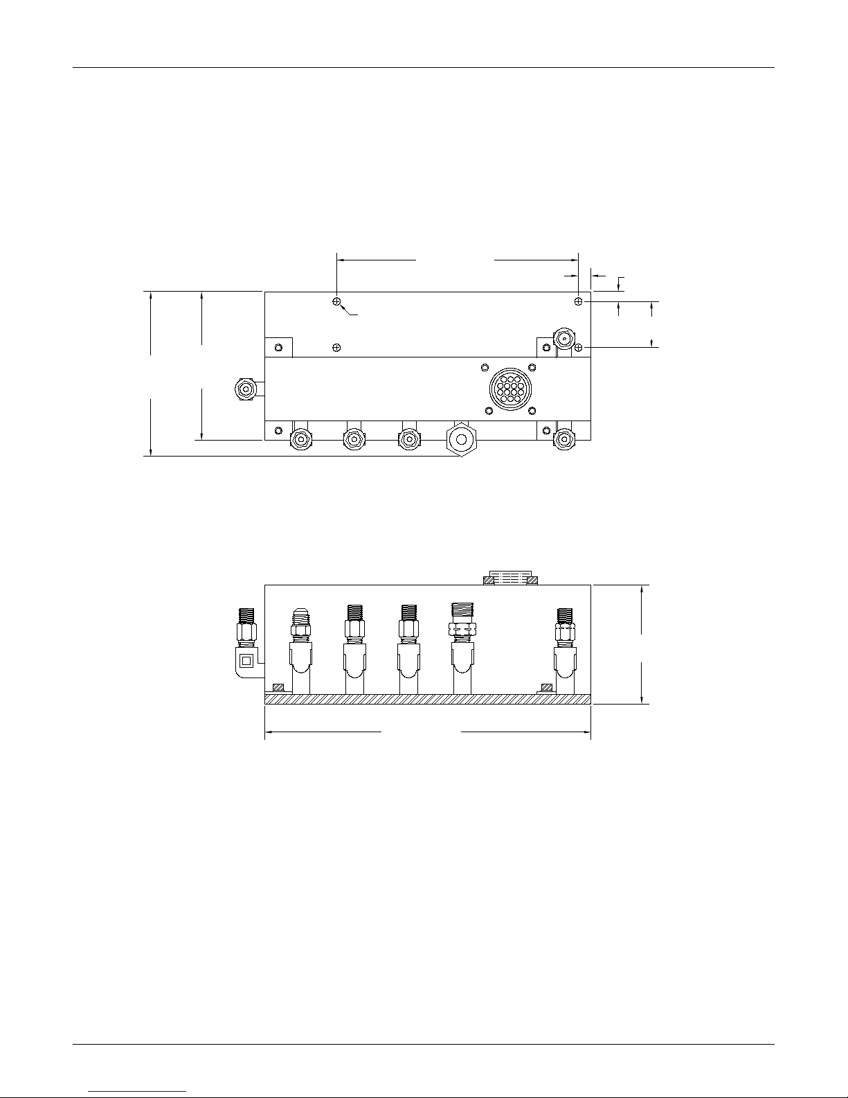
5-Gang Manifold Specifications
Part Number .................................................... BK300075
Weight .............................................................. 6 lbs (2.7 kg)
4.20"
[107]
3.80"
[97]
6.18" [157]
0.327" [8.3]
0.25" [6.4]
1.18" [30]
8.35" [212]
3.035" [77]
(4) 0.187" [4.8] Mounting Holes

Section 2: Specifications Spirit II User’s Manual
This information is subject to the controls of the Export Administration Regulations [EAR]. This information shall not be provided to
non-U.S. persons or transferred by any means to any location outside the United States contrary to the requirements of the EAR.
2-12
Airborne Noise Emissions
The system generates high noise levels while cutting. Depending on the size of the
cutting area, distance from the cutting torch, and arc current cutting level, acceptable
noise levels may be exceeded. Proper ear protection should be used as defined by
local or national codes. The following chart gives the noise levels generated by the
system when operating at 150 amps, 130 arc volts. The measurements were made
with a sound level meter.
Distance From Torch
A-Weighted Sound
Pressure Level
C-Weighted Sound
Pressure Level
1 meter horizontal / 1.6
meters above the
workpiece
97 dB 94 dB
The maximum noise level is 121 dB at a distance of 3 inches (76.2 mm) from the torch
while cutting at 150 amps, 130 arc volts.
Electromagnetic Compatibility (EMC)
The 380V 50/60Hz and 415V 50/60Hz CE marked Spirit II plasma cutting systems are
manufactured to comply with the European standard EN 60974-10 (Electromagnetic
compatibility (EMC) – Product standard for arc welding equipment). Information about
the EMC standard EN 60974-10 can be found in Appendix A.

Spirit II User’s Manual Section 3: Installation
This information is subject to the controls of the Export Administration Regulations [EAR]. This information shall not be provided to
non-U.S. persons or transferred by any means to any location outside the United States contrary to the requirements of the EAR.
3-1
Section 3: Installation
Initial Inspection
All systems undergo full testing before being shipped from the factory. In the unlikely
event that one of the components is defective or missing, please contact customer
service so that a replacement can be sent. Also, special care has been taken in the
packaging of the system. If the system was damaged during shipment, file a claim with
the shipping company, and then contact customer service to order the necessary parts.
Component Placement
Plasma Power Supply
The power supply should be lifted by a forklift or pallet jack. In order to prevent
damaging the power supply, the forks should be of adequate length to protrude on the
far side of the power supply. The proper location of the power supply will provide
dependable service and reduce periodic maintenance time. Choose a location that will
provide unrestricted air movement into and out of the power supply. Maintain at least
24 inches of space on all sides of the unit. The location should subject the power
supply to the least amount of dust, dirt, moisture, and corrosive vapors. The surface on
which the power supply is located should have a grade of no greater than 10º to
eliminate the risk of toppling over. The power supply must be cleaned as often as
necessary to prevent the accumulation of metallic dust inside the unit. See Section 2
for unit dimensions.
Automatic Gas Console (AGC)
The AGC is usually mounted on the gantry of the cutting machine. See Section 2 for
mounting dimensions.
Plasma Console
The plasma console should be mounted near the CNC controller so that it is easy
accessible by the operator. See Section 2 for mounting dimensions.
Arc Starting Console (ASC)
The ASC should be mounted in a convenient location that is away from other electronic
control devices. The ASC with CleanStrike™ Technology offers significantly reduced
emissions compared to ASC with RHF, however, the high voltage pulse generated
inside the unit may interfere with the operation of sensitive control electronics. The ASC
is usually mounted on the gantry of the cutting machine or on the cutting table. See
Section 2 for mounting dimensions.
5-Gang Manifold
The 5-gang manifold assembly must be mounted within 6 feet (1.8 m) of the torch. See
Section 2 for mounting dimensions.

Section 3: Installation Spirit II User’s Manual
This information is subject to the controls of the Export Administration Regulations [EAR]. This information shall not be provided to
non-U.S. persons or transferred by any means to any location outside the United States contrary to the requirements of the EAR.
3-2
2-Gang Manifold
The 2-gang manifold assembly must be mounted to the torch. See Section 2 for
mounting dimensions.
Torch
The torch must be installed on the positioner of an arc voltage control (height control)
capable of maintaining the cutting arc voltage within 1 arc volt. The arc voltage must be
adjustable in 1 arc volt increments. The positioner must be rigid to ensure cut quality
and a torch collision sensor is highly recommended. See Section 2 for mounting
dimensions.
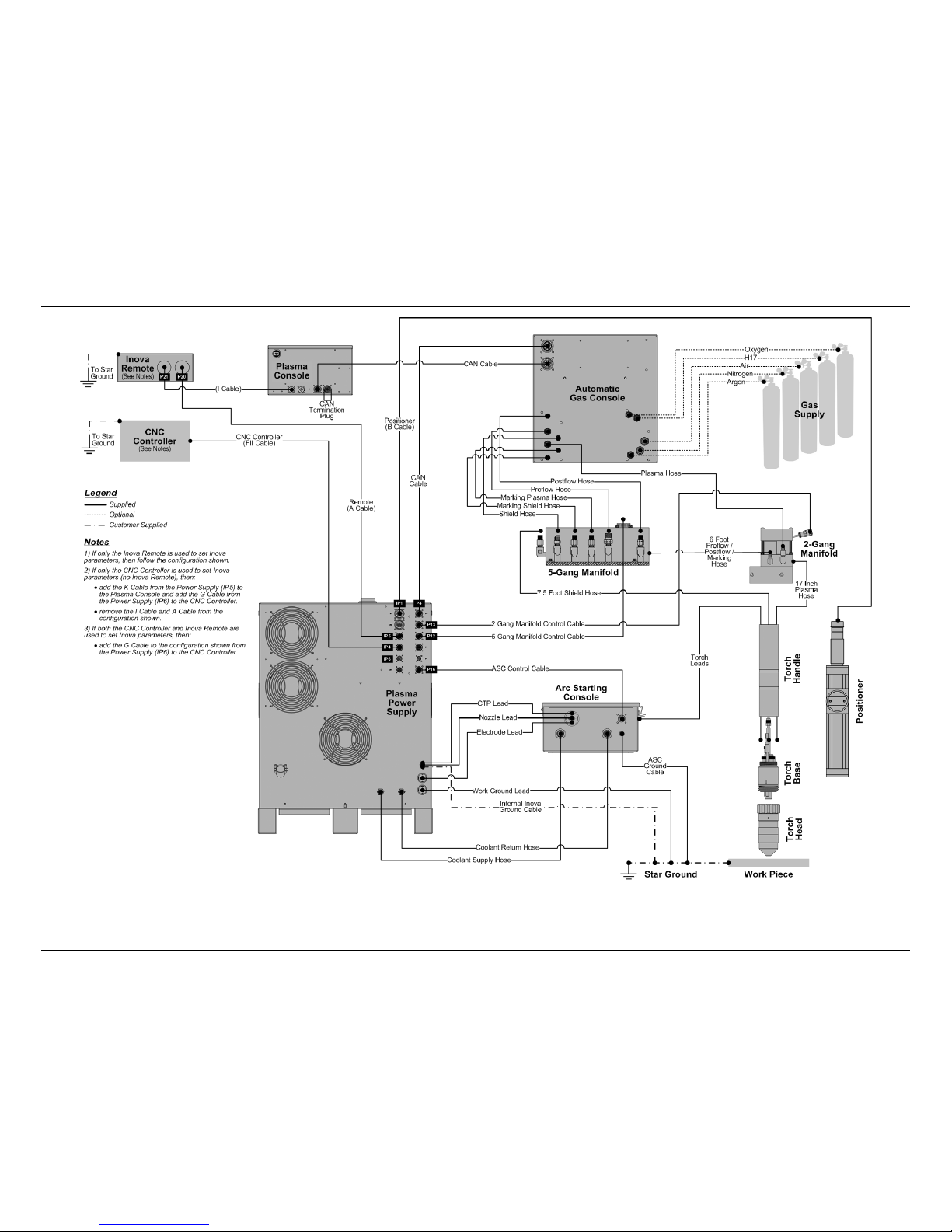
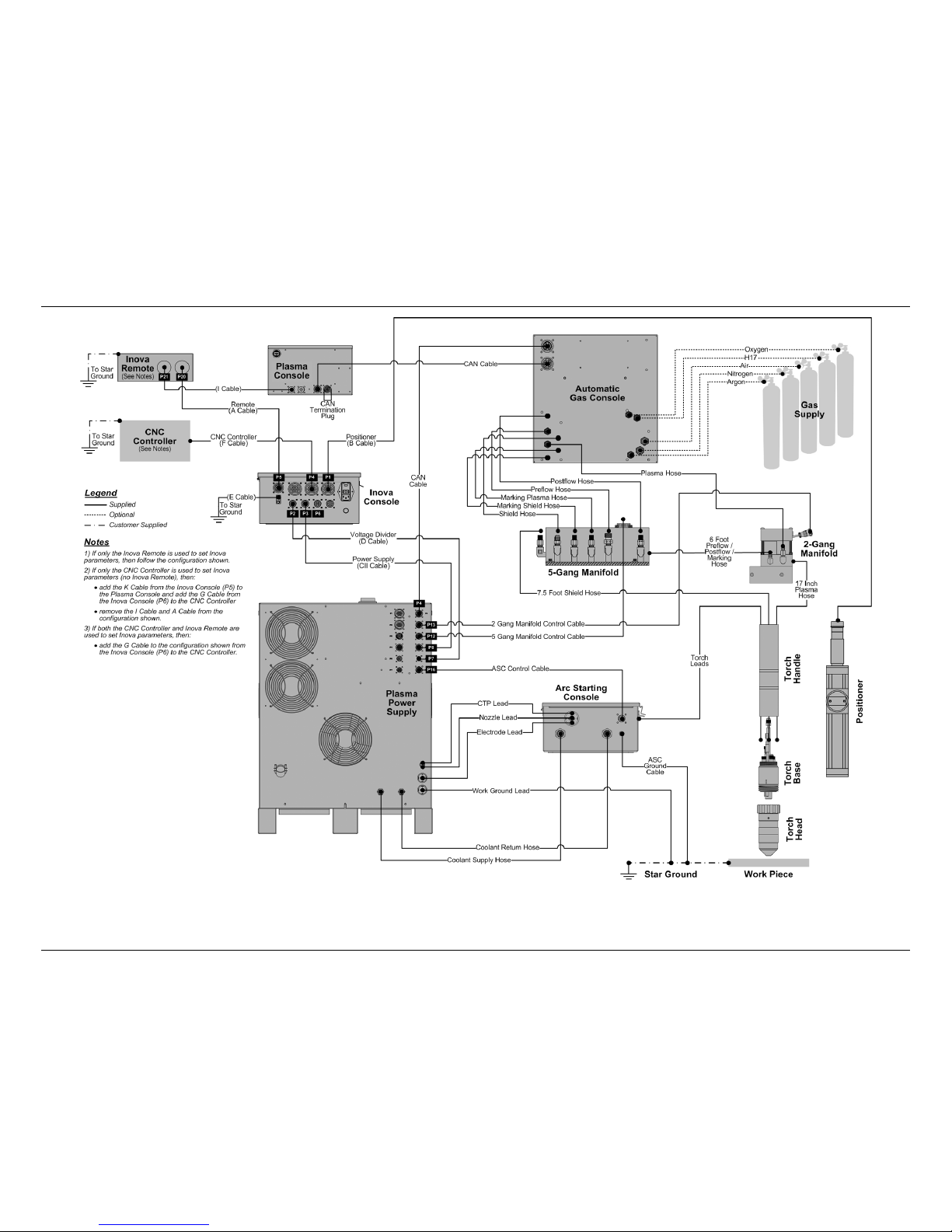
System Interconnection
The Spirit II system interconnection diagrams on the following pages will assist in the
planning and installation of the system as well as identifying cables and hoses upon
receipt.
The optional Inova torch height control is also shown to assist with its connections,
whether as an external console or internal to the plasma power supply.

Spirit II User’s Manual Section 3: Installation
This information is subject to the controls of the Export Administration Regulations [EAR]. This information shall not be provided to
non-U.S. persons or transferred by any means to any location outside the United States contrary to the requirements of the EAR.
3-3
Figure 1a: Spirit II System (AGC, Internal Inova, ASC with RHF)

Section 3: Installation Spirit II User’s Manual
This information is subject to the controls of the Export Administration Regulations [EAR]. This information shall not be provided to
non-U.S. persons or transferred by any means to any location outside the United States contrary to the requirements of the EAR.
3-4
Figure 1b: Spirit II System (AGC, External Inova, ASC with RHF)
Spirit II User’s Manual Section 3: Installation
This information is subject to the controls of the Export Administration Regulations [EAR]. This information shall not be provided to
non-U.S. persons or transferred by any means to any location outside the United States contrary to the requirements of the EAR.
3-5
Figure 1c: Spirit II System (AGC, Internal Inova, ASC with CleanStrike™ Technology)
Section 3: Installation Spirit II User’s Manual
This information is subject to the controls of the Export Administration Regulations [EAR]. This information shall not be provided to
non-U.S. persons or transferred by any means to any location outside the United States contrary to the requirements of the EAR.
3-6
Figure 1d: Spirit II System (AGC, External Inova, ASC with CleanStrike™ Technology)
 Loading...