

Lincoln Electric SPEEDTEC 400S, SPEEDTEC 500S Operator's Manual
IM3020
01/2010
Rev. 1
SPEEDTEC 400S & 500S
OPERATOR’S MANUAL
MANUALE OPERATIVO
BEDIENUNGSANLEITUNG
MANUAL DE INSTRUCCIONES
MANUEL D'UTILISATION
BRUKSANVISNING OG DELELISTE
GEBRUIKSAANWIJZING
BRUKSANVISNING
INSTRUKCJA OBSŁUGI
KÄYTTÖOHJE
MANUAL DE INSTRUÇÕES
ИНСТРУКЦИЯ ПО ЭКСПЛУАТАЦИИ
LINCOLN ELECTRIC BESTER S.A.
ul. Jana III Sobieskiego 19A, 58-260 Bielawa, Poland
www.lincolnelectric.eu

English EnglishI
Declaration of conformity
LINCOLN ELECTRIC BESTER S.A.
Declares that the welding machine:
SPEEDTEC 400S
SPEEDTEC 500S
conforms to the following directives:
2006/95/CEE, 2004/108/CEE
and has been designed in compliance with the
following standards:
EN 60974-1, EN 60974-10
(2009)
Paweł Lipiński
Operations Director
LINCOLN ELECTRIC BESTER S.A., ul. Jana III Sobieskiego 19A, 58-260 Bielawa, Poland
12/05

English EnglishII
12/05
THANKS! For having choosen the QUALITY of the Lincoln Electric products.
• Please Examine Package and Equipment for Damage. Claims for material damaged in shipment must be notified
immediately to the dealer.
• For future reference record in the table below your equipment identification information. Model Name, Code &
Serial Number can be found on the machine rating plate.
Model Name:
………………...…………………………….…………………………………………………………………………………………..
Code & Serial number:
………………….……………………………………………….. …………………………………………………….……………..
Date & Where Purchased:
…………………………………………………………………... ……………………….…………………………………………..
ENGLISH INDEX
Safety .............................................................................................................................................................................. 1
Installation and Operator Instructions .............................................................................................................................. 2
Electromagnetic Compatibility (EMC) .............................................................................................................................. 4
Technical Specifications .................................................................................................................................................. 5
WEEE..............................................................................................................................................................................6
Spare Parts...................................................................................................................................................................... 6
Electrical Schematic ........................................................................................................................................................6
Accessories ..................................................................................................................................................................... 6
English English1
Safety
11/04
WARNING
This equipment must be used by qualified personnel. Be sure that all installation, operation, maintenance and repair
procedures are performed only by qualified person. Read and understand this manual before operating this equipment.
Failure to follow the instructions in this manual could cause serious personal injury, loss of life, or damage to this
equipment. Read and understand the following explanations of the warning symbols. Lincoln Electric is not responsible
for damages caused by improper installation, improper care or abnormal operation.
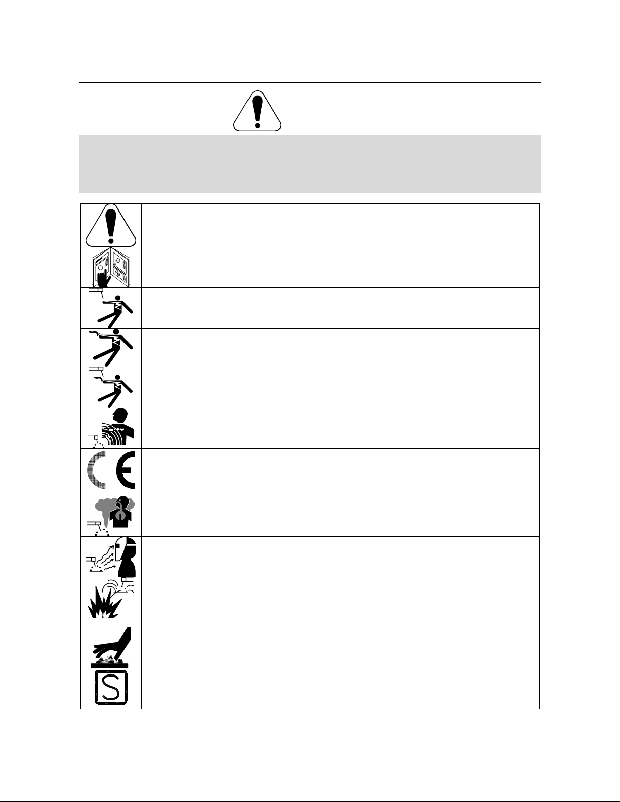
WARNING: This symbol indicates that instructions must be followed to avoid serious personal injury,
loss of life, or damage to this equipment. Protect yourself and others from possible serious injury or
death.
READ AND UNDERSTAND INSTRUCTIONS: Read and understand this manual before operating
this equipment. Arc welding can be hazardous. Failure to follow the instructions in this manual could
cause serious personal injury, loss of life, or damage to this equipment.
ELECTRIC SHOCK CAN KILL: Welding equipment generates high voltages. Do not touch the
electrode, work clamp, or connected work pieces when this equipment is on. Insulate yourself from
the electrode, work clamp, and connected work pieces.
ELECTRICALLY POWERED EQUIPMENT: Turn off input power using the disconnect switch at the
fuse box before working on this equipment. Ground this equipment in accordance with local electrical
regulations.
ELECTRICALLY POWERED EQUIPMENT: Regularly inspect the input, electrode, and work clamp
cables. If any insulation damage exists replace the cable immediately. Do not place the electrode
holder directly on the welding table or any other surface in contact with the work clamp to avoid the
risk of accidental arc ignition.
ELECTRIC AND MAGNETIC FIELDS MAY BE DANGEROUS: Electric current flowing through any
conductor creates electric and magnetic fields (EMF). EMF fields may interfere with some
pacemakers, and welders having a pacemaker shall consult their physician before operating this
equipment.
CE COMPLIANCE: This equipment complies with the European Community Directives.
FUMES AND GASES CAN BE DANGEROUS: Welding may produce fumes and gases hazardous to
health. Avoid breathing these fumes and gases. To avoid these dangers the operator must use
enough ventilation or exhaust to keep fumes and gases away from the breathing zone.
ARC RAYS CAN BURN: Use a shield with the proper filter and cover plates to protect your eyes from
sparks and the rays of the arc when welding or observing. Use suitable clothing made from durable
flame-resistant material to protect you skin and that of your helpers. Protect other nearby personnel
with suitable, non-flammable screening and warn them not to watch the arc nor expose themselves to
the arc.
WELDING SPARKS CAN CAUSE FIRE OR EXPLOSION: Remove fire hazards from the welding
area and have a fire extinguisher readily available. Welding sparks and hot materials from the welding
process can easily go through small cracks and openings to adjacent areas. Do not weld on any
tanks, drums, containers, or material until the proper steps have been taken to insure that no
flammable or toxic vapors will be present. Never operate this equipment when flammable gases,
vapors or liquid combustibles are present.
WELDED MATERIALS CAN BURN: Welding generates a large amount of heat. Hot surfaces and
materials in work area can cause serious burns. Use gloves and pliers when touching or moving
materials in the work area.
SAFETY MARK: This equipment is suitable for supplying power for welding operations carried out in
an environment with increased hazard of electric shock.
English English2
CYLINDER MAY EXPLODE IF DAMAGED: Use only compressed gas cylinders containing the
correct shielding gas for the process used and properly operating regulators designed for the gas and
pressure used. Always keep cylinders in an upright position securely chained to a fixed support. Do
not move or transport gas cylinders with the protection cap removed. Do not allow the electrode,
electrode holder, work clamp or any other electrically live part to touch a gas cylinder. Gas cylinders
must be located away from areas where they may be subjected to physical damage or the welding
process including sparks and heat sources.
Installation and Operator Instructions
Read this entire section before installation or operation
of the machine.
Location and Environment
This machine will operate in harsh environments.
However, it is important that simple preventative
measures are followed to assure long life and reliable
operation:
• Do not place or operate this machine on a surface
with an incline greater than 15° from horizontal.
• Do not use this machine for pipe thawing.
• This machine must be located where there is free
circulation of clean air without restrictions for air
movement to and from the air vents. Do not cover
the machine with paper, cloth or rags when
switched on.
• Dirt and dust that can be drawn into the machine
should be kept to a minimum.
• This machine has a protection rating of IP23. Keep
it dry when possible and do not place it on wet
ground or in puddles.
• Locate the machine away from radio controlled
machinery. Normal operation may adversely affect
the operation of nearby radio controlled machinery,
which may result in injury or equipment damage.
Read the section on electromagnetic compatibility in
this manual.
• Do not operate in areas with an ambient
temperature greater than 40°C.
Duty cycle and Overheating
The duty cycle of a welding machine is the percentage of
time in a 10 minute cycle at which the welder can
operate the machine at rated welding current.
Example: 60% duty cycle:
Welding for 6 minutes. Break for 4 minutes.
Excessive extension of the duty cycle will cause the
thermal protection circuit to activate.
Minutes or decrease
duty cycle
Input Supply Connection
Installation and mains outlet socket shall be made and
protected according to appropriate rules.
Check the input voltage, phase, and frequency supplied
to this machine before turning it on. Verify the
connection of grounding wires from the machine to the
input source. The allowable input voltages is 3x400V
50/60Hz. For more information about input supply refer
to the technical specification section of this manual and
to the rating plate of the machine.
Make sure that the amount of mains power available
from the input supply (connection) is adequate for
normal operation of the machine. The necessary fuse
(or circuit breaker) and cable sizes are indicated in the
technical specification section of this manual.
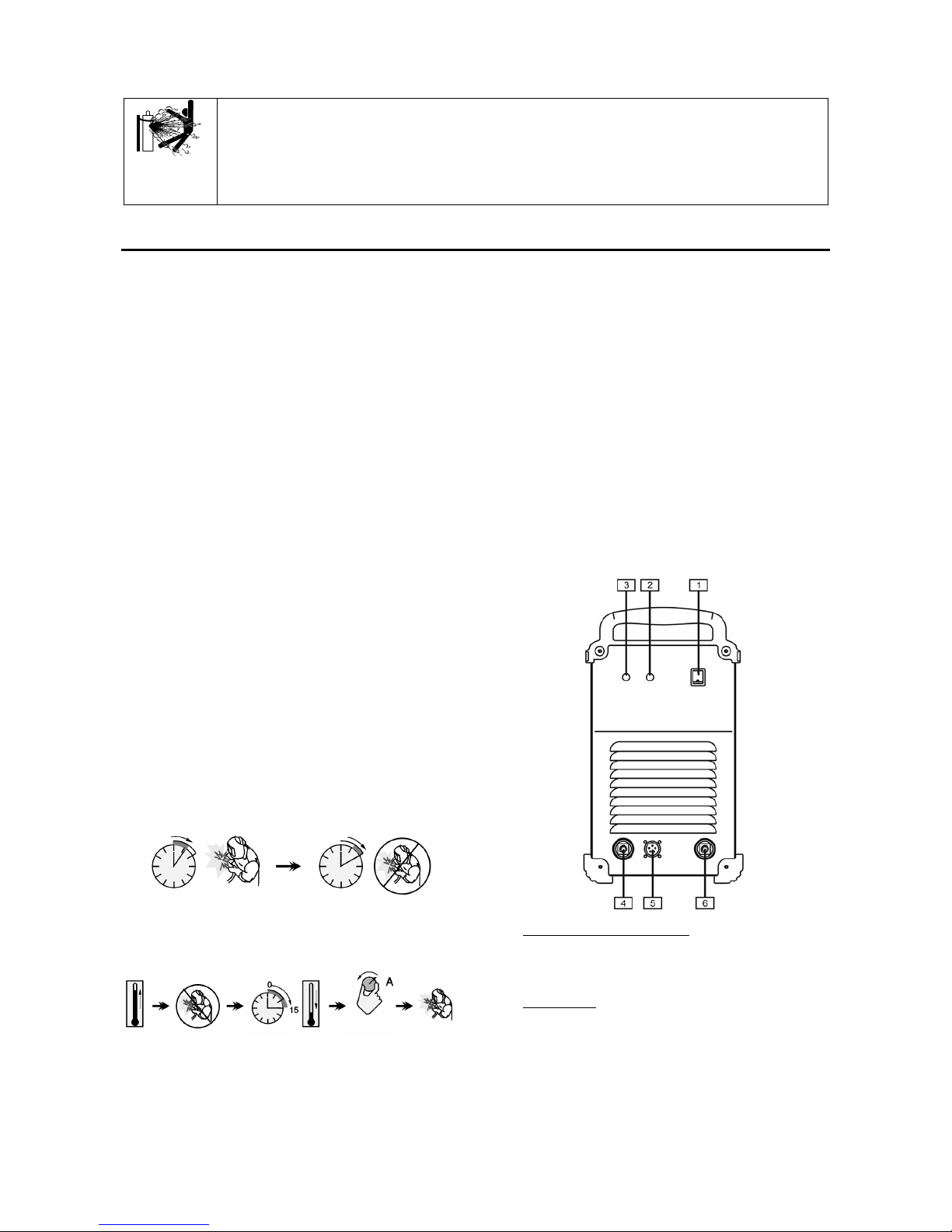
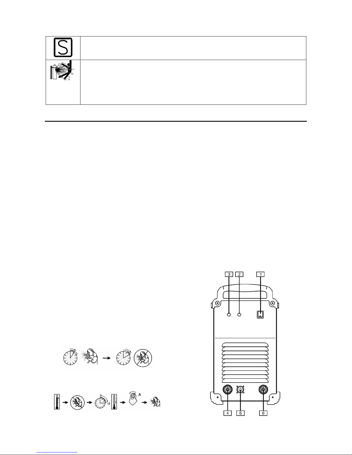
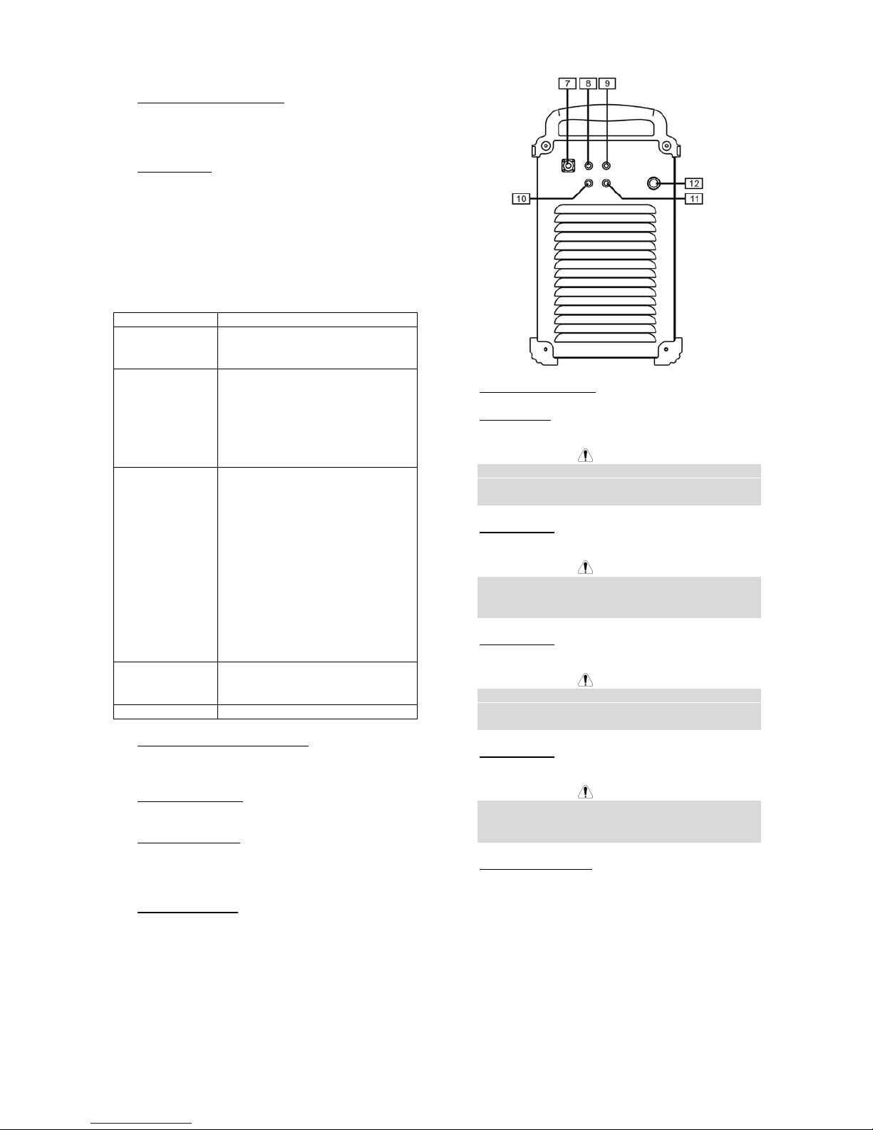
Refer to points [1] and [12] of the images below.
Output Connections
Refer to points [4], [5] and [6] of the images below.
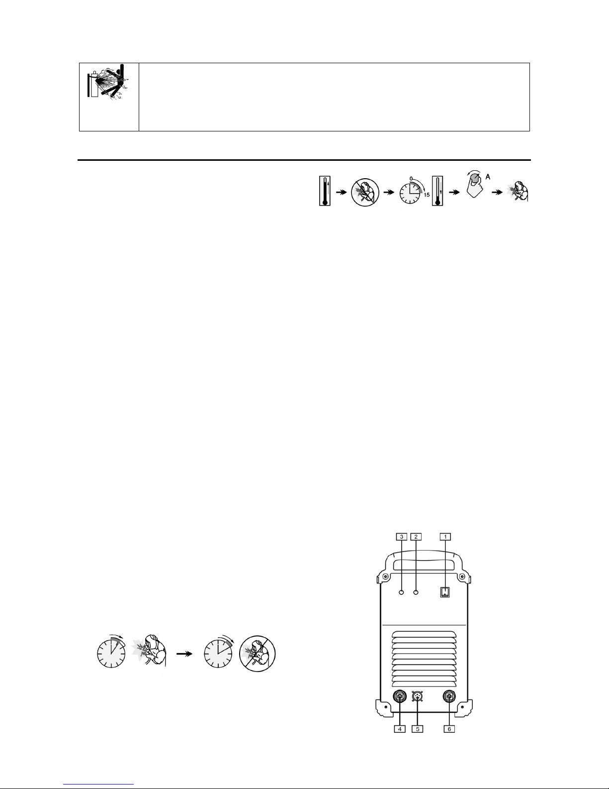
Controls and Operational Features
1. Power Switch ON/OFF (O/I): It controls the
machine power input. Be sure the power source is
connected to the mains supply before turning power
on ("I").
2. Status Light: A two color light that indicates system
errors. Normal operation is steady green light. Error
conditions are indicated, per TABLE 1.
NOTE: The status light will flash green, and
sometimes red and green, for up to one minute
when the machine is first turned on. This is a
normal situation as the machine goes through a self
test at power up.
English English3
TABLE 1
Light Condition Meaning
Steady Green System O.K. Power source
comunicating normaly with wire
feeder.
Blinking Green Occurs during a reset, and indicates
the power source is mapping
(identyfying) each component in the
systems. Normal for first 1-10
seconds after power is turned on, or
if the system configuration is
changed during operation.
Alternating
Green and Red
Non-recoverable system fault. If the
PS status light is flashing any
combination of red and green, errors
are present in power source.
Individual code digits are flashed in
red with a long pause between digits.
If more then one code is present, the
codes will be separated by green
light. Read the error code before the
machine is turned off.
If occurs, to clear the error try to turn
Off the machine, wait for a few
seconds, then turn ON again. If the
error remains, a maintenance is
required. Please contact the nearest
technical service center or Lincoln
Electric and report the error code
readed.
Steady Red Non recoverable hardware fault.
Generally indicates nothing is
connected to the power source wire
feeder receptacle.
Blinking Red Not applicable.
3. Thermal Indicator Light: It indicates that the
machine is overloaded or that the cooling is not
sufficient.
4. Negative Output Socket: For connecting the return
welding cable.
5. Control Socket: 5 pins receptacle for wire feeder or
remote controller connection. To communication
wire feeder with power source is used ArcLink
protocol.
6. Positive Output Socket: Allows the connection, with
the power cable, to the wire feeder.
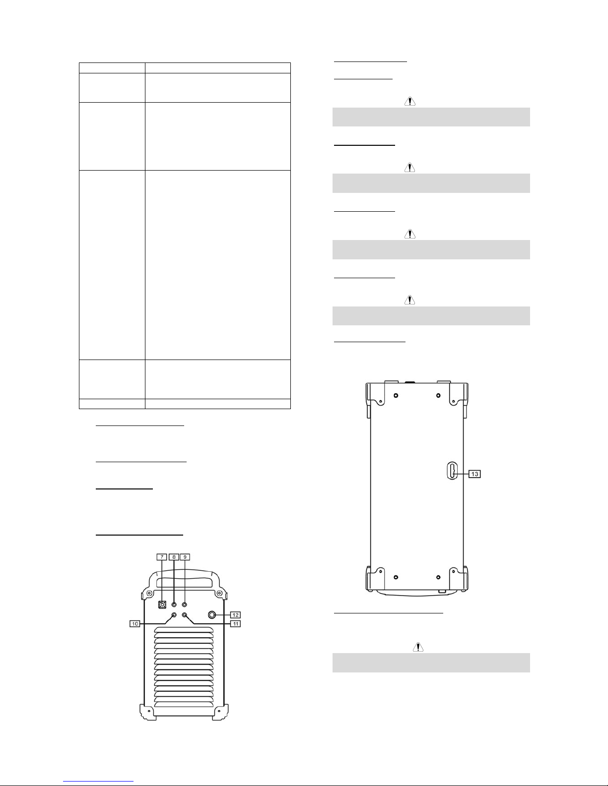
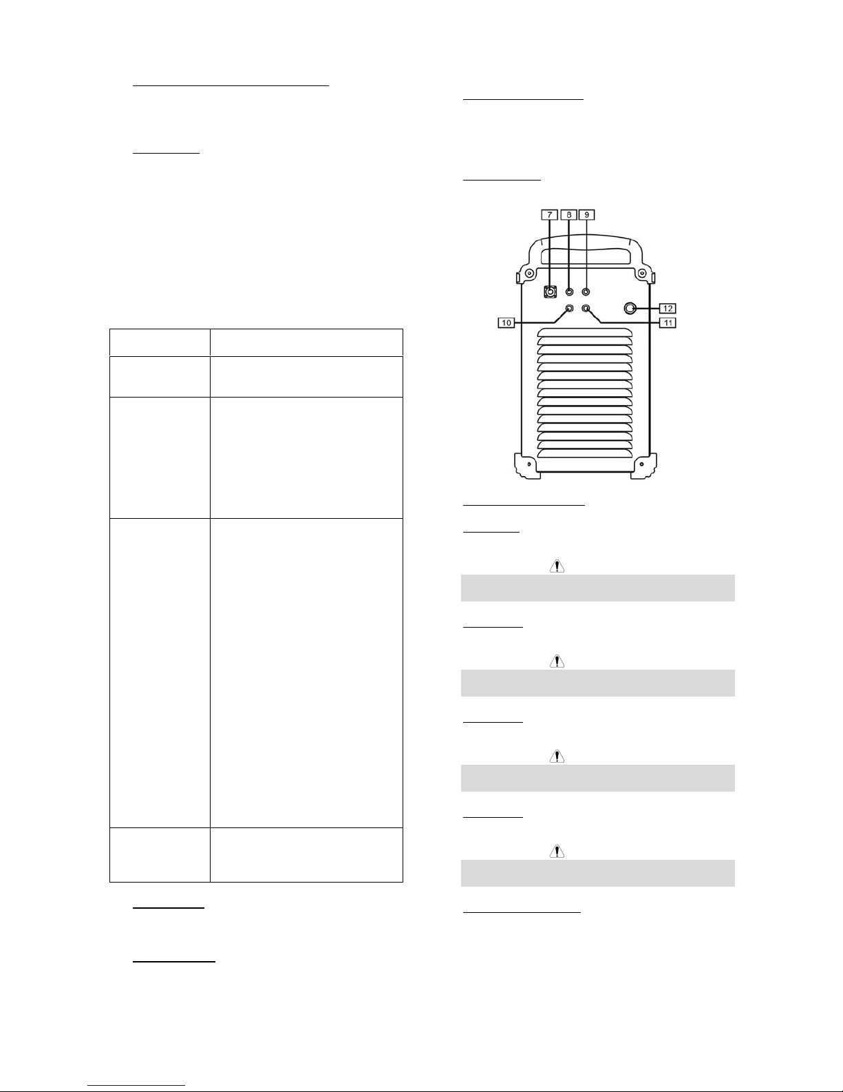
7. Gas Heater Socket: U
sup
= 24VAC, P
max
= 80W.
8. Fuse Socket F3: The recommended fuse
12,5A/400V (6,3x32mm).
WARNING
You have to use fuses with technical specifications
given by the producer.
9. Fuse Socket F4: The recommended fuse
6,3A/400V (6,3x32mm).
WARNING
You have to use fuses with technical specifications
given by the producer.
10. Fuse Socket F1: The recommended fuse 2A/400V
(6,3x32mm).
WARNING
You have to use fuses with technical specifications
given by the producer.
11. Fuse Socket F2: The recommended fuse 2A/400V
(6,3x32mm).
WARNING
You have to use fuses with technical specifications
given by the producer.
12. Power Input Cable: Connect the proper plug to the
input cable then into the rated output according to
appropriate rules. Only qualified personnel shall
connect this plug.
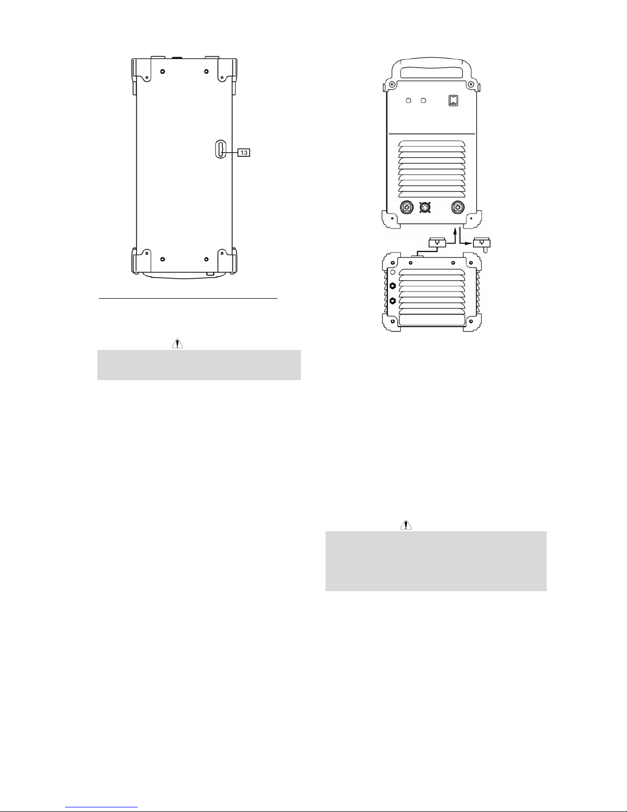
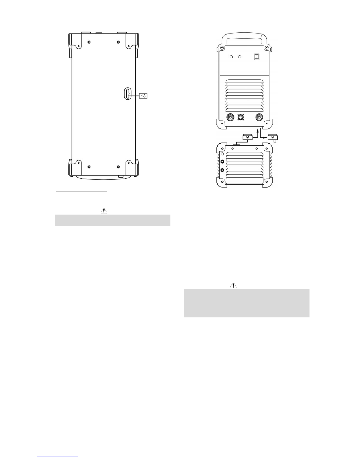
13. Cooler Power Supply Socket: The socket has an
output of 400VAC to supplying water cooler (it is
protected by the circuit breaker [10]).
WARNING
Read and understand the cooler manual before
connecting it to the machine.
Welding Cables Connections
Insert the plug of the work cable into the socket [4]. The
other end of this cable connects to the work piece with
the work clamp.
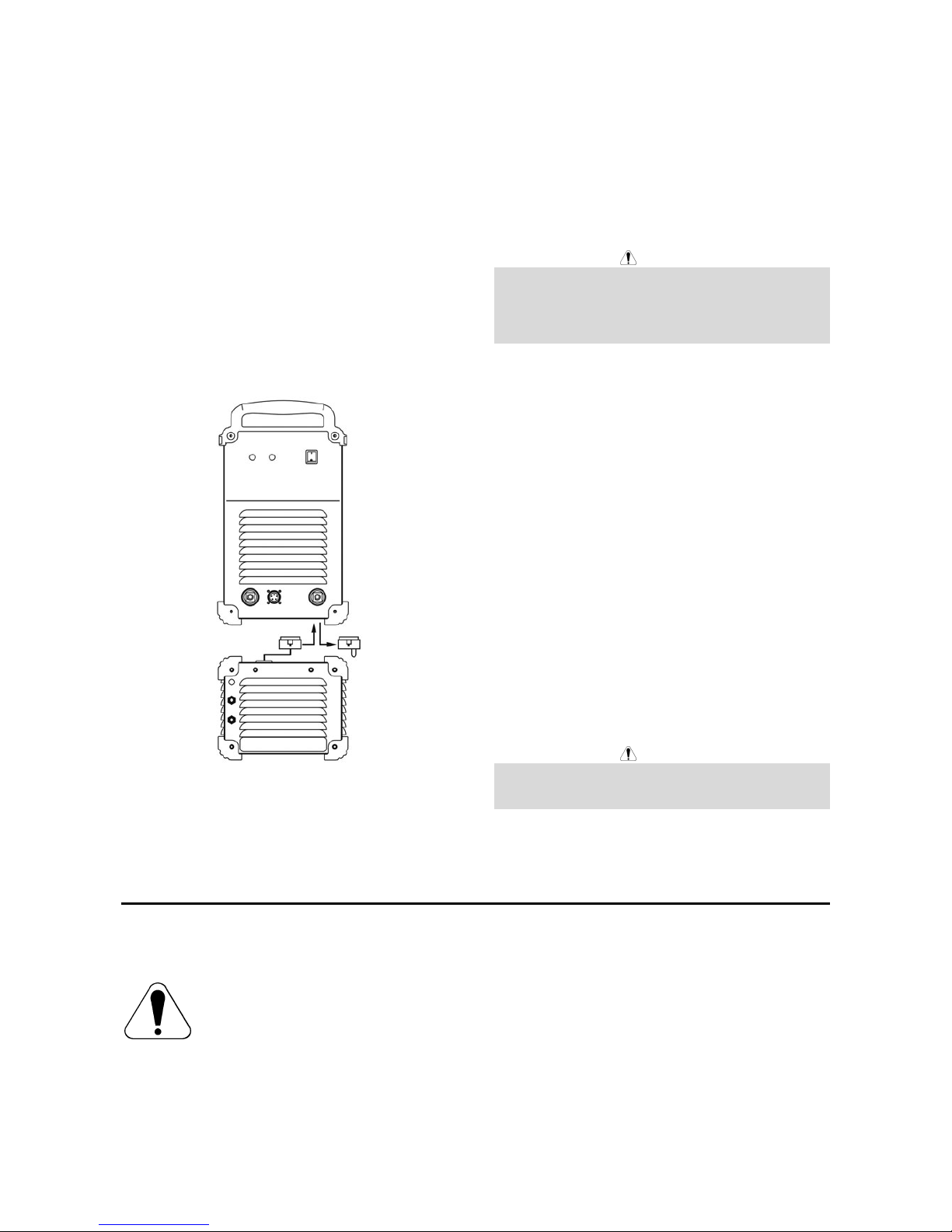
English English4
Connect the wire feeder LF 45 to the power source:
• Insert the positive welding cable into the output
socket [6].
• Insert the wire feeder control cable into the socket
[5] (see Accessories, Source/wire feeder cable
K10349-PG-xM or K10349-PGW-xM).
Use the shortest possible cable lengths.
Water Cooler Connections
Connect the water cooler Coolarc 45 to the power
source:
• Remove the rubber grommet from the bottom panel.
• Remove the jumper from the cooler power supply
socket [13].
• Thread the water cooler supply plug through the
rubber grommet.
• Insert the water cooler cable into the socket [13].
• Instert the rubber grommet into the bottom panel
hole.
Machine and Circuit Protection
Power Source is protected against overheating, overload
and accidental short-circuits.
If the machine is overheated, the thermal protection
circuit will decrease the output current to 0. The thermal
protection indicator [3] will turn on.
The Power Source is also electronically protected
against overload and accidental short-circuit. The
overload and short-circuit protection circuit automatically
reduces the output current to a safe value when it
detects an overload.
Maintenance
WARNING
For any maintenance or repair operations it is
recommended to contact the nearest technical service
center or Lincoln Electric. Maintenance or repairs
performed by unauthorized service centers or personnel
will null and void the manufacturers warranty.
The frequency of the maintenance operations may vary
in accordance with the working environment where the
machine is placed.
Any noticeable damage should be reported immediately.
Routine maintenance (everyday)
• Check cables and connections integrity. Replace, if
necessary.
• Remove the spatters from the welding gun nozzle.
Spatters could interfere with the shielding gas flow
to the arc.
• Check the welding gun condition: replace it, if
necessary.
• Check condition and operation of the cooling fan.
Keep clean its airflow slots.
Periodic maintenance (every 200 working hours
but not more rarely than once a year)
Perform the routine maintenance and, in addition:
• Keep clean the machine. Using a dry ( and low
pressure) airflow, remove the dust from the external
case and from inside of the cabinet.
• Check and tighten all screws.
WARNING
Mains supply network must be disconnected from the
machine before each maintenance and service. After
each repair, perform proper tests to ensure safety.
Electromagnetic Compatibility (EMC)
11/04
This machine has been designed in accordance with all relevant directives and standards. However, it may still generate
electromagnetic disturbances that can affect other systems like telecommunications (telephone, radio, and television) or
other safety systems. These disturbances can cause safety problems in the affected systems. Read and understand
this section to eliminate or reduce the amount of electromagnetic disturbance generated by this machine.
The operator must install and operate this equipment as described in this manual. If any electromagnetic
disturbances are detected the operator must put in place corrective actions to eliminate these disturbances
with, if necessary, assistance from Lincoln Electric.
Before installing the machine, the operator must check the work area for any devices that may malfunction because of
electromagnetic disturbances. Consider the following.
• Input and output cables, control cables, and telephone cables that are in or adjacent to the work area and the
machine.
• Radio and/or television transmitters and receivers. Computers or computer controlled equipment.
• Safety and control equipment for industrial processes. Equipment for calibration and measurement.
English English5
• Personal medical devices like pacemakers and hearing aids.
• Check the electromagnetic immunity for equipment operating in or near the work area. The operator must be sure
that all equipment in the area is compatible. This may require additional protection measures.
• The dimensions of the work area to consider will depend on the construction of the area and other activities that are
taking place.
Consider the following guidelines to reduce electromagnetic emissions from the machine.
• Connect the machine to the input supply according to this manual. If disturbances occur if may be necessary to take
additional precautions such as filtering the input supply.
• The output cables should be kept as short as possible and should be positioned together. If possible connect the
work piece to ground in order to reduce the electromagnetic emissions. The operator must check that connecting
the work piece to ground does not cause problems or unsafe operating conditions for personnel and equipment.
• Shielding of cables in the work area can reduce electromagnetic emissions. This may be necessary for special
applications.
WARNING
EMC classification of this product is class A in accordance with electromagnetic compatibility standard EN 60974-10 and
therefore the product is designed to be used in an industrial environment only.
WARNING
The Class A equipment is not intended for use in residential locations where the electrical power is provided by the public
low-voltage supply system. There may be potential difficulties in ensuring electromagnetic compatibility in those
locations, due to conducted as well as radiated disturbances.
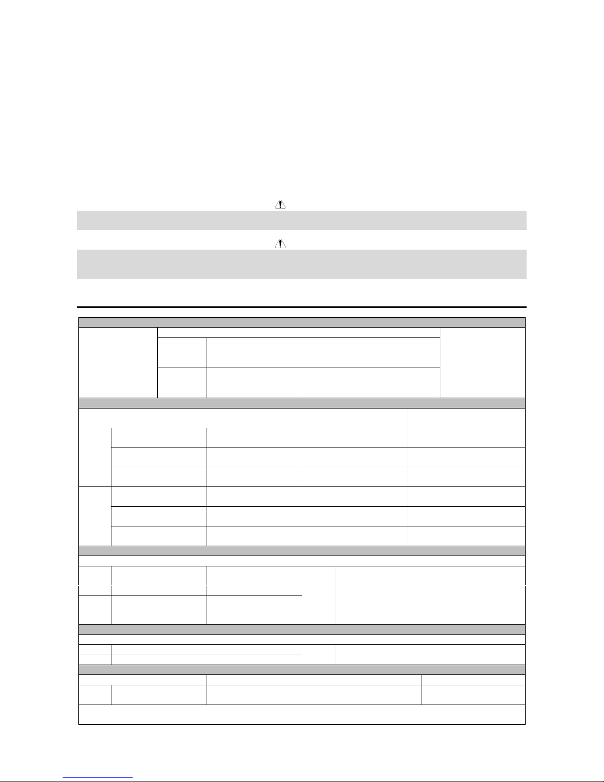
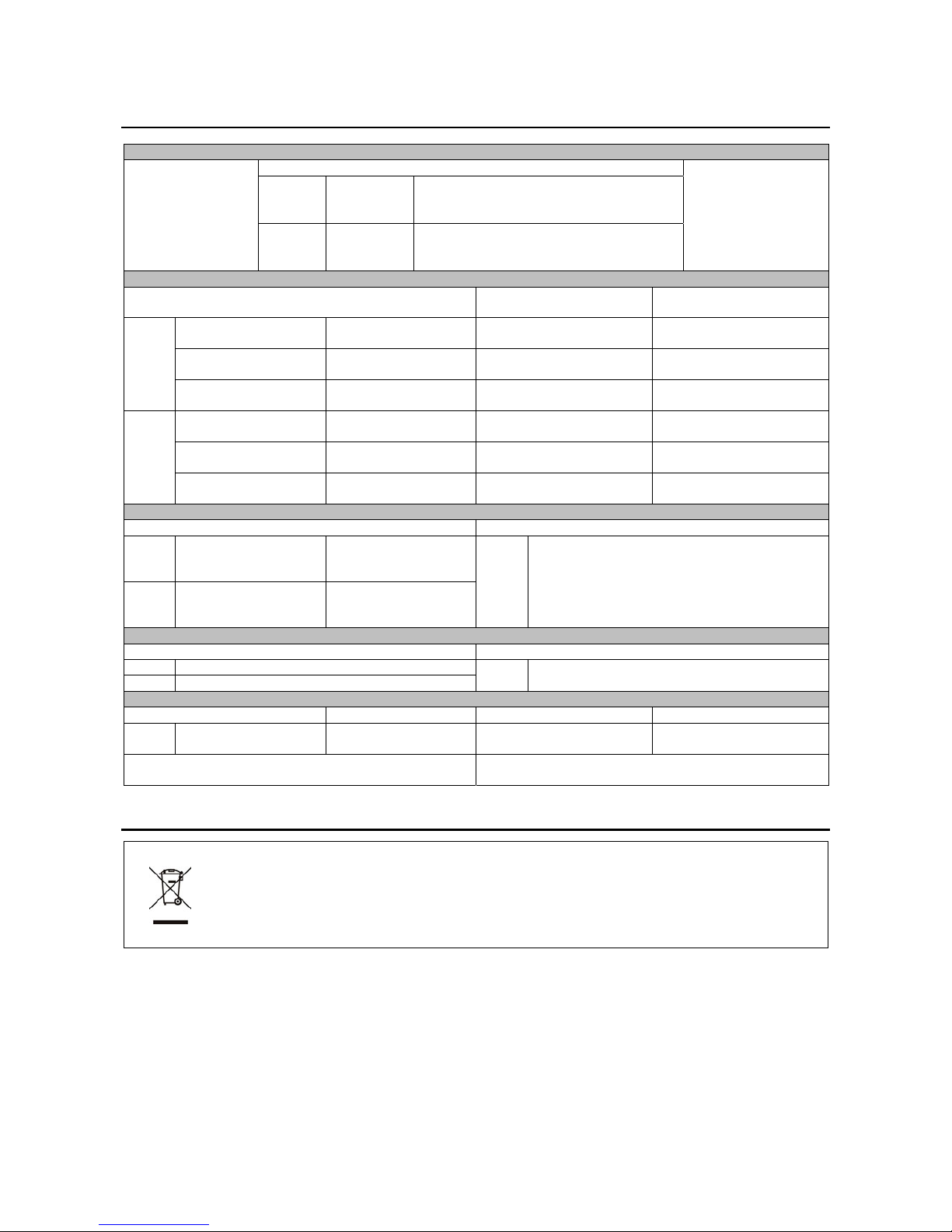
Technical Specifications
INPUT
Input Power at Rated Output
SMAW 17.1 kVA @ 80% duty cycle
GTAW-DC 12.8 kVA @ 80% duty cycle
400S:
GMAW 16.2 kVA @ 80% duty cycle
SMAW 24.0 kVA @ 40% duty cycle
GTAW-DC 18.4 kVA @ 40% duty cycle
Input Voltage
400 V ± 10%
Three Phase
500S:
GMAW 23.3 kVA @ 40% duty cycle
Frequency
50/60 Hz
RATED OUTPUT AT 40°C
Duty Cycle
(Based on a 10 min. period)
Output Current Output Voltage
80% 400 A 36.0 Vdc
SMAW
100% 390 A 35.5 Vdc
80% 400 A 26.0 Vdc
GTAW-DC
100% 390 A 25.5 Vdc
80% 400 A 34.0 Vdc
400S:
GMAW
100% 390 A 33.5 Vdc
40% 500 A 40.0 Vdc
SMAW
100% 390 A 35.5 Vdc
40% 500 A 30.0 Vdc
GTAW-DC
100% 390 A 25.5 Vdc
40% 500 A 39.0 Vdc
500S:
GMAW
100% 390 A 33.5 Vdc
OUTPUT RANGE
Welding Current Range Maximum Open Circuit Voltage
SMAW 5 A – 400 A
GTAW-DC 5 A – 400 A
400S:
GMAW 20 A – 400 A
SMAW 5 A – 500 A
GTAW-DC 5 A – 500 A
500S:
GMAW 20 A – 500 A
400S:
500S:
73 Vdc
RECOMMENDED INPUT CABLE AND FUSE SIZES
Fuse or Circuit Breaker Size Input Power Cable
400S:
25 A, Z curve recommended
500S:
40 A, Z curve recommended
400S:
500S:
4 x 4 mm
2
PHYSICAL DIMENSIONS
Height Width Length Weight
400S:
500S:
476 mm 305 mm 600 mm 50 kg
Operating Temperature
-10°C to +40°C
Storage Temperature
-25°C to +55°C
English English6
WEEE
07/06
English
Do not dispose of electrical equipment together with normal waste!
In observance of European Directive 2002/96/EC on Waste Electrical and Electronic Equipment (WEEE)
and its implementation in accordance with national law, electrical equipment that has reached the end of its
life must be collected separately and returned to an environmentally compatible recycling facility. As the
owner of the equipment, you should get information on approved collection systems from our local
representative.
By applying this European Directive you will protect the environment and human health!
Spare Parts
12/05
Part List reading instructions
• Do not use this part list for a machine if its code number is not listed. Contact the Lincoln Electric Service
Department for any code number not listed.
• Use the illustration of assembly page and the table below to determine where the part is located for your particular
code machine.
• Use only the parts marked "X" in the column under the heading number called for in the assembly page (# indicate
a change in this printing).
First, read the Part List reading instructions above, then refer to the "Spare Part" manual supplied with the machine, that
contains a picture-descriptive part number cross-reference.
Electrical Schematic
Refer to the "Spare Part" manual supplied with the machine.
Accessories
K10349-PG-XM Source wire/feeder cable (gas). Available in 5, 10,15, 20, 25 or 30m
K10349-PGW-XM Source wire/feeder cable (gas and water). Available in 5, 10,15, 20, 25 or 30m
K14067-1 Water cooler Coolarc 45
K14075-1 Assembly kit: Speedtec – Coolarc 45 (brackets)
K14074-1 Undercarriage with cylinder holder
K14033-1 Work cable

Italiano ItalianoI
Dichiarazione di conformità
LINCOLN ELECTRIC BESTER S.A.
Dichiara che il generatore per saldatura tipo:
SPEEDTEC 400S
SPEEDTEC 500S
è conforme alle seguenti direttive:
2006/95/CEE, 2004/108/CEE
ed è stato progettato in conformità alle seguenti
norme:
EN 60974-1, EN 60974-10
(2009)
Paweł Lipiński
Operations Director
LINCOLN ELECTRIC BESTER S.A., ul. Jana III Sobieskiego 19A, 58-260 Bielawa, Poland
12/05
Italiano ItalianoII
12/05
GRAZIE! Per aver scelto la QUALITÀ dei prodotti Lincoln Electric.
• Esamini Imballo ed Equipaggiamento per rilevare eventuali danneggiamenti. Le richieste per materiali danneggiati
dal trasporto devono essere immediatamente notificate al rivenditore.
• Per ogni futuro riferimento, compilare la tabella sottostante con le informazioni di identificazione equipaggiamento.
Modello, Codice (Code) e Matricola (Serial Number) sono reperibili sulla targa dati della macchina.
Modello:
………………...…………………………….…………………………………………………………………………………………..
Code (codice) e Matricola:
………………….……………………………………………….. …………………………………………………….……………..
Data e Luogo d’acquisto:
…………………………………………………………………... ……………………….…………………………………………..
INDICE ITALIANO
Sicurezza......................................................................................................................................................................... 1
Installazione e Istruzioni Operative..................................................................................................................................2
Compatibilità Elettromagnetica (EMC)............................................................................................................................. 5
Specifiche Tecniche......................................................................................................................................................... 6
RAEE (WEEE)................................................................................................................................................................. 6
Parti di Ricambio .............................................................................................................................................................7
Schema Elettrico .............................................................................................................................................................7
Accessori.........................................................................................................................................................................7
Italiano Italiano1
Sicurezza
11/04
AVVERTENZA
Questa macchina deve essere impiegata solo da personale qualificato. Assicuratevi che tutte le procedure di
installazione, impiego, manutenzione e riparazione vengano eseguite solamente da persone qualificate. Leggere e
comprendere questo manuale prima di mettere in funzione la macchina. La mancata osservanza delle istruzioni di
questo manuale può provocare seri infortuni, anche mortali, alle persone, o danni alla macchina. Leggere e
comprendere le spiegazioni seguenti sui simboli di avvertenza. La Lincoln Electric non si assume alcuna responsabilità
per danni conseguenti a installazione non corretta, incuria o impiego in modo anormale.
AVVERTENZA: Questo simbolo indica che occorre seguire le istruzioni per evitare seri infortuni,
anche mortali, alle persone o danni a questa macchina. Proteggete voi stessi e gli altri dalla
possibilità di seri infortuni anche mortali.
LEGGERE E COMPRENDERE LE ISTRUZIONI: Leggere e comprendere questo manuale prima di
far funzionare la macchina. La saldatura ad arco può presentare dei rischi. La mancata osservanza
delle istruzioni di questo manuale può provocare seri infortuni, anche mortali, alle persone o danni alla
macchina.
LA FOLGORAZIONE ELETTRICA E’ MORTALE: Le macchine per saldatura generano tensioni
elevate. Non toccate l’elettrodo, il morsetto di massa o pezzi da saldare collegati alla macchina
quando la macchina è accesa. Mantenetevi isolati elettricamente da elettrodo, morsetto e pezzi
collegati a questo.
MACCHINA CON ALIMENTAZIONE ELETTRICA: Togliere l’alimentazione con l’interruttore ai fusibili
prima di svolgere operazioni su questa macchina. Mettere la macchina a terra secondo le normative
vigenti.
MACCHINA CON ALIMENTAZIONE ELETTRICA: Ispezionare periodicamente i cavi di
alimentazione, all’elettrodo e al pezzo. Se si riscontrano danni all’isolamento sostituire
immediatamente il cavo. Non posare la pinza portaelettrodo direttamente sul banco di saldatura o
qualsiasi altra superficie in contatto con il morsetto di massa per evitare un innesco involontario
dell’arco.
I CAMPI ELETTRICI E MAGNETICI POSSONO ESSERE PERICOLOSI: Il passaggio di corrente
elettrica in un conduttore produce campi elettromagnetici. Questi campi possono interferire con alcuni
cardiostimolatori (“pacemaker”) e i saldatori con un cardiostimolatore devono consultare il loro medico
su possibili rischi prima di impiegare questa macchina.
CONFORMITÀ CE: Questa macchina è conforme alle Direttive Europee.
FUMI E GAS POSSONO ESSERE PERICOLOSI: La saldatura può produrre fumi e gas dannosi alla
salute. Evitate di respirare questi fumi e gas. Per evitare il pericolo l’operatore deve disporre di una
ventilazione o di un'estrazione di fumi e gas che li allontanino dalla zona in cui respira.
I RAGGI EMESSI DALL’ARCO BRUCIANO: Usate una maschera con schermatura adatta a
proteggervi gli occhi da spruzzi e raggi emessi dall’arco mentre saldate o osservate la saldatura.
Indossare indumenti adatti in materiale resistente alla fiamma per proteggere il corpo, sia vostro che
dei vostri aiutanti. Le persone che si trovano nelle vicinanze devono essere protette da schermature
adatte, non infiammabili, e devono essere avvertite di non guardare l’arco e di non esporvisi.
GLI SPRUZZI DI SALDATURA POSSONO PROVOCARE INCENDI O ESPLOSIONI: Allontanare
dall'area di saldatura quanto può prendere fuoco e tenere a portata di mano un estintore. Gli spruzzi
o altri materiali ad alta temperatura prodotti dalla saldatura attraversano con facilità eventuali piccole
aperture raggiungendo le zone vicine. Non saldare su serbatoi, bidoni, contenitori o altri materiali fino
a che non si sia fatto tutto il necessario per assicurarsi dell'assenza di vapori infiammabili o nocivi.
Non impiegare mai questa macchina se vi è presenza di gas e/o vapori infiammabili o combustibili
liquidi.
I MATERIALI SALDATI BRUCIANO: Il processo di saldatura produce moltissimo calore. Ci si può
bruciare in modo grave con le superfici e materiali caldi della zona di saldatura. Impiegare guanti e
pinze per toccare o muovere materiali nella zona di saldatura.
Italiano Italiano2
MARCHIO DI SICUREZZA: Questa macchina è adatta a fornire energia per operazioni di saldatura
svolte in ambienti con alto rischio di folgorazione elettrica.
LE BOMBOLE POSSONO ESPLODERE SE SONO DANNEGGIATE: Impiegate solo bombole
contenenti il gas compresso adatto al processo di saldatura utilizzato e regolatori di flusso, funzionanti
regolarmente, progettati per il tipo di gas e la pressione in uso. Le bombole vanno tenute sempre in
posizione verticale e assicurate con catena ad un sostegno fisso. Non spostate le bombole senza il
loro cappello di protezione. Evitate qualsiasi contatto dell’elettrodo, della sua pinza, del morsetto di
massa o di ogni altra parte in tensione con la bombola del gas. Le bombole gas vanno collocate
lontane dalle zone dove possano restare danneggiate dal processo di saldatura con relativi spruzzi e
da fonti di calore.
Installazione e Istruzioni Operative
Leggere tutta questa sezione prima di installare e
impiegare la macchina.
Collocazione e ambiente
Questa macchina è in grado di funzionare in ambienti
difficili. E’ comunque importante seguire delle semplici
misure di prevenzione per garantirne una lunga durata e
un funzionamento affidabile.
• Non collocare o impiegare la macchina su superfici
inclinate più di 15° rispetto all’orizzontale.
• Non usare questa macchina per sgelare tubi.
• La macchina va collocata ove vi sia una circolazione
di aria pulita senza impedimenti al suo movimento in
entrata e uscita dalle feritoie. Non coprire la
macchina con fogli di carta, panni o stracci quando
è accesa.
• Tenere al minimo polvere e sporco che possano
entrare nella macchina.
• Questa macchina ha una protezione di grado IP23.
Tenetela più asciutta possibile e non posatela su
suolo bagnato o dentro pozzanghere.
• Disponete la macchina lontana da macchinari
controllati via radio. Il suo funzionamento normale
può interferire negativamente sul funzionamento di
macchine controllate via radio poste nelle vicinanze,
con conseguenze di infortuni o danni materiali.
Leggete la sezione sulla compatibilità
elettromagnetica di questo manuale.
• Non impiegate la macchina in zone ove la
temperatura ambiente supera i 40°C.
Fattore di Intermittenza e
Surriscaldamento
Il fattore di intermittenza di una saldatrice è la
percentuale di tempo su un periodo di 10 minuti durante
la quale si può far funzionare la macchina alla corrente
nominale corrispondente.
Esempio: Fattore di intermittenza 60%:
Saldatura per 6 minuti. Interruzione per 4 minuti.
Il superamento del fattore di intermittenza provoca
l’attivazione del circuito di protezione termica.
Minuti o ridurre il fattore
di intermittenza
Collegamento all’alimentazione
L’installazione e la presa dalla rete di alimentazione
devono essere realizzate e protette secondo la
normativa vigente.
Prima di accendere la macchina verificare tensione, fasi
e frequenza dell’alimentazione. Controllare il
collegamento dei cavi di messa a terra fra la macchina e
la sua alimentazione. La tensione di alimentazione
ammissibile è 3x400V 50/60Hz. Per ulteriori
informazioni sull’alimentazione fare riferimento alla
Sezione Specifiche tecniche del manuale e alla targhetta
dati della macchina.
Assicuratevi che l’alimentazione fornisca una potenza
sufficiente per il funzionamento normale della macchina.
Nella sezione “Specifiche tecniche” di questo manuale
sono indicate le dimensioni necessarie per i fusibili
ritardati (o interruttori automatici) e cavi.
Riferirsi ai punti [1] e [12] delle immagini sotto.
Collegamenti in uscita
Riferirsi ai punti [4], [5] e [6] delle immagini sotto.
Comandi e possibilità operative
Italiano Italiano3
1. Interruttore accensione ON/OFF (O/I): Alimenta o
disalimenta la macchina. Assicuratevi che il
generatore sia collegato alla corretta tensione di
alimentazione prima di accenderlo ("I").
2. LED di stato: LED a due coliri che indica lo stato
della macchina ed eventuali anomalie/errori. In
condizioni normali è stabilmente acceso con
colorazione verde. In caso di anomalia/errore fare
riferimento alla tabella 1.
NOTA: Il LED di stato lampeggia con colorazione
verde ed in alcuni casi alterna la colorazione da
verde a rosso nel primo minuto di accensione della
macchina. Questa è una condizione normale in
quanto la macchina, all’accensione, esegue un auto
test.
TABELLA 1
Colorazione e
stato LED
Definizione
Verde Fisso Il sitema è OK. Il generatore
comunica regolrmente con il
trainafilo.
Verde
Lampeggiante
Si ha durante il reset ed indica che
il generatore è nella fase di
“mapping” (identificazione) di
ciascun componente del sistema.
Normalmente questo avviene nei
primi 1-10 secondi dopo
l’accensione o se la configurazione
del sistema cambiata durante le
operazioni di utilizzo.
Rosso
Lampeggiante
Eroore di sistema non ripristinabile.
Se il LED lampeggia
alternativamente verde e rosso con
qualsiasi configurazione un guasto
è presente all’interno del
generatore.
I codici di errore sono forniti dai
lampeggi rossi con lunghe pause
tra un lampeggio e l’altro. Se più di
un codice di errore è presente un
lampeggio verde separerà i due
codici. Decodificare il codice di
errore prima di spegnere la
macchina.
Se possibile cercare di resettare
l’errore spegnendo e riaccendendo
il generatore. Se l’errore persiste
contattare il centro assistenza
Lincoln Electric autorizzato ed
indicare il codice di errore fornito
dalla macchina.
Rosso fisso Guasto Hardware non ripristinabile.
Generalmente indica che non c’è
nessun trainafilo connesso al
generatore.
3. Spia Termico: Indica che la macchina è in
sovratemperatura o che la ventilazione è
insufficiente.
4. Uscita negativa: Su questa boccola va connesso il
cavo che proviene dalla pinza collegata al banco di
saldatura o direttamente dal pezzo da saldare.
5. Connettore di controllo: Presa a 5 pin dove deve
essere collegato il cavo di controllo del trainafilo o il
comando remoto. Per la comunicazione tra
generatore e trainafilo è utilizzato un controllo
digitale con protocollo ArcLink.
6. Uscita positiva: Permette la connessione del cavo
di potenza con il trainafilo.
7. Presa riscaldatore Gas: U
sup
= 24VAC, P
max
= 80W.
8. Fusibile F3: Utilizzare fusibile da 12,5A/400V
(6,3x32mm).
AVVERTENZA
Utilizzare fusibili con caratteristiche tecniche fornite
dal produttore.
9. Fusibile F4: Utilizzare fusibile da 6,3A/400V
(6,3x32mm).
AVVERTENZA
Utilizzare fusibili con caratteristiche tecniche fornite
dal produttore.
10. Fusibile F1: Utilizzare fusibile da 2A/400V
(6,3x32mm).
AVVERTENZA
Utilizzare fusibili con caratteristiche tecniche fornite
dal produttore.
11. Fusibile F2: Utilizzare fusibile da 2A/400V
(6,3x32mm).
AVVERTENZA
Utilizzare fusibili con caratteristiche tecniche fornite
dal produttore.
12. Cavo di alimentazione: Collegare la spina corretta
sul cavo di alimentazione in base alle normative
vigenti del paese di utilizzo. Solo personale
qualificato può collegare la spina.
Italiano Italiano4
13. Presa collegamento gruppo di raffreddamento: La
presa ha un’uscita di 400VAC per l’alimentazione
del gruppo di raffreddamento (il circuito è protetto
da un interruttore ripristinabile [10]).
AVVERTENZA
Leggere attentamente il manule di istruzioni del
gruppo di raffreddamento prima di collegarlo alla
macchina.
Collegamento dei cavi di saldatura
Collegare il cavo “work” nella presa [4]. Collegare l’altra
estremità di questo cavo al banco di lavoro o al pezzo da
saldaremediante la pinza.
Collegare il trainafilo LF45 al generatore:
• Inserire il cavo positivo nella presa [6].
• Collegare il cavo di controllo del trainafilo nella
presa [5] (leggere sezione accessory, Cavi
generatore/trainafilo K10349-PG-xM o K10349PGW-xM).
Utilizzate la minima lunghezza di cavi possibile.
Collegamento Gruppo Raffreddamento
Collegare il gruppo di raffreddamento Coolarc 45 al
generatore:
• Rimuovere la copertura di gomma presente sul
fondo del generatore.
• Rimuovere il ponticello dalla presa del gruppo di
raffreddamento [13].
• Passare la presa attraverso il tappo di gomma.
• Inserire il cavo del gruppo di di raffreddamento nella
presa [13].
• Riposizionare il tappo di gomma sul pannello
inferiore della macchina.
Generatore e Circuiti di Protezione
Il generatore è protetto dalla sovratemperatura,
sovracorrente e corti circuiti accidentali.
Se la macchina è surriscaldata il circuito di protezione
contro la sovratemperatura ridurrà a 0 la corrente di
uscita. L’indicatore di sovratemperatura si accenderà
[3].
Il generatore è protetto anche elettronicamente contro
sovracorrenti e corti circuiti accidentali. Il circuito di
protezione automaticamente ridurrà la corrente di uscita
ad un valore di sicurezza quando un sovraccarico viene
individuato.
Manutenzione
AVVERTENZA
Per ogni operazione di manutenzione o riparazione si
raccomanda di rivolgersi al più vicino centro di
assistenza tecnica della Lincoln Electric. Manutenzioni o
riparazioni effettuate da personale o centri di servizio
non autorizzati fanno decadere la garanzia del
fabbricante.
La frequenza delle operazioni di manutenzione può
essere variata in funzione dell’ambiente in cui la
macchina si trova a lavorare.
Qualsiasi danno venga notato va immediatamente
riferito a chi di dovere.
Italiano Italiano5
Manutenzione corrente (quotidiana)
• Controllare che cavi e collegamenti siano integri.
Sostituirli, se necessario.
• Rimuovere gli spruzzi dal cono della torcia. Gli
spruzzi possono interferire con il flusso del gas di
protezione verso l’arco.
• Controllare lo stato della torcia: sostituirla, se
necessario.
• Controllare stato e funzionamento del ventilatore di
raffreddamento. Mantenerne pulite le feritoie.
Manutenzione periodica (ogni 200 ore di lavoro,
ma non meno di una volta all’anno)
Eseguire la manutenzione corrente e, in aggiunta:
• Pulire la macchina. Usare un getto d’aria asciutto e
a bassa pressione per rimuovere la polvere
dall’involucro esterno e dall’interno.
• Controllare e ristringere tutte le viti.
AVVERTENZA
Prima di svolgere qualsiasi operazione di manutenzione
e servizio staccare la macchina dalla rete di
alimentazione. Dopo ogni riparazione, eseguire le prove
necessarie ad assicurare la sicurezza.
Compatibilità Elettromagnetica (EMC)
11/04
Questa macchina è stata progettata nel rispetto di tutte le direttive e normative in materia. Tuttavia può generare dei
disturbi elettromagnetici che possono interferire con altri sistemi come le telecomunicazioni (telefono, radio o televisione)
o altri sistemi di sicurezza. I disturbi possono provocare problemi nella sicurezza dei sistemi interessati. Leggete e
comprendete questa sezione per eliminare o ridurre il livello dei disturbi elettromagnetici generati da questa macchina.
L’operatore deve installare e impiegare la macchina come precisato in questo manuale. Se si riscontrano
disturbi elettromagnetici l’operatore deve porre in atto azioni correttive per eliminarli, avvalendosi, se
necessario, dell’assistenza della Lincoln Electric.
Prima di installare la macchina, controllate se nell’area di lavoro vi sono dispositivi il cui funzionamento potrebbe risultare
difettoso a causa di disturbi elettromagnetici. Prendete in considerazione i seguenti:
• Cavi di entrata o di uscita, cavi di controllo e cavi telefonici collocati nell’area di lavoro, presso la macchina o nelle
adiacenze di questa.
• Trasmettitori e/o ricevitori radio o televisivi. Computers o attrezzature controllate da computer.
• Impianti di sicurezza e controllo per processi industriali. Attrezzature di taratura e misurazione.
• Dispositivi medici individuali come cardiostimolatori (pacemakers) o apparecchi acustici.
• Verificare che macchine e attrezzature funzionanti nell’area di lavoro o nelle vicinanze siano immuni da possibili
disturbi elettromagnetici. L’operatore deve accertare che tutte le attrezzature e dispositivi nell’area siano compatibili.
A questo scopo può essere necessario disporre misure di protezione aggiuntive.
• L’ampiezza dell’area di lavoro da prendere in considerazione dipende dalla struttura dell’area e dalle altre attività
che vi si svolgono.
Per ridurre le emissioni elettromagnetiche della macchina tenete presenti le seguenti linee guida.
• Collegare la macchina alla fonte di alimentazione come indicato da questo manuale. Se vi sono disturbi, può essere
necessario prendere altre precauzioni, come un filtro sull’alimentazione.
• I cavi in uscita vanno tenuti più corti possibile e l’uno accanto all’altro. Se possibile mettere a terra il pezzo per
ridurre le emissioni elettromagnetiche. L’operatore deve controllare che questa messa a terra non provochi
problemi o pericoli alla sicurezza del personale e della macchina e attrezzature.
• Si possono ridurre le emissioni elettromagnetiche schermando i cavi nell’area di lavoro. Per impieghi particolari
questo può diventare necessario.
AVVERTENZA
In accordo con la Normativa di compatibilità elettromagnetica EN60974-10 questo prodotto è classificato in classe A e
pertanto è progettato per essere utilizzato solamente in ambienti industriali.
AVVERTENZA
Gli equipaggiamenti in classe A non sono prodotti per essere usati in ambienti residenziali dove l’energia elettrica in
bassa tensione è fornita da un sistema pubblico. A causa di disturbi condotti ed irradiati ci possono essere delle difficoltà
a garantire la compatibilità elettromagnetica in questi ambienti.
Italiano Italiano6
Specifiche Tecniche
ALIMENTAZIONE
Potenza assorbita per uscita nominale
SMAW 17.1 kVA @ per fattore di intermittenza 80%
GTAW-DC 12.8 kVA @ per fattore di intermittenza 80%
400S:
GMAW 16.2 kVA @ per fattore di intermittenza 80%
SMAW 24.0 kVA @ per fattore di intermittenza 40%
GTAW-DC 18.4 kVA @ per fattore di intermittenza 40%
Tensione di
alimentazione
400 V ± 10%
Trifase
500S:
GMAW 23.3 kVA @ per fattore di intermittenza 40%
Frequenza
50/60 Hz
USCITA NOMINALE a 40°C
Fattore di intermittenza
(su periodo di 10 minuti)
Corrente in uscita Tensione nominale in uscita
80% 400 A 36.0 Vdc
SMAW
100% 390 A 35.5 Vdc
80% 400 A 26.0 Vdc
GTAW-DC
100% 390 A 25.5 Vdc
80% 400 A 34.0 Vdc
400S:
GMAW
100% 390 A 33.5 Vdc
40% 500 A 40.0 Vdc
SMAW
100% 390 A 35.5 Vdc
40% 500 A 30.0 Vdc
GTAW-DC
100% 390 A 25.5 Vdc
40% 500 A 39.0 Vdc
500S:
GMAW
100% 390 A 33.5 Vdc
USCITA
Gamma corrente di saldatura Massima tensione a vuoto
SMAW 5 A – 400 A
GTAW-DC 5 A – 400 A
400S:
GMAW 20 A – 400 A
SMAW 5 A – 500 A
GTAW-DC 5 A – 500 A
500S:
GMAW 20 A – 500 A
400S:
500S:
73 Vdc
DATI FISICI – DIMENSIONI
Fusibile o Interruttore Cavo di alimentazione
400S:
25 A, Curva Z raccomandata
500S:
40 A, Curva Z raccomandata
400S:
500S:
4 x 4 mm
2
DATI FISICI – DIMENSIONI
Altezza Larghezza Lunghezza Peso
400S:
500S:
476 mm 305 mm 600 mm 50 kg
Temperatura di impiego
–10°C a +40°C
Temperatura di immagazzinamento
-25°C a +55°C
RAEE (WEEE)
07/06
Italiano
Non gettare le apparecchiature elettriche tra i rifiuti domestici!
In ottemperanza alla Direttiva Europea 2002/96/CE sui Rifiuti di Apparechiature Elettriche ed Elettroniche
(RAEE) e la sua attuazione in conformità alle norme nazionali, le apparecchiature elettriche esauste
devono essere raccolte separatamente e restituite ad una organizzazione di riciclaggio ecocompatibile.
Come proprietario dell’apparecchiatura, Lei potrà ricevere informazioni circa il sistema approvato di
raccolta, dal nostro rappresentante locale.
Applicando questa Direttiva Europea Lei contribuirà a migliorare l’ambiente e la salute!

Italiano Italiano7
Parti di Ricambio
12/05
Parti di Ricambio: istruzioni per la lettura
• Non utilizzare questa lista se il code della macchina non è indicato. Contattare l’Assistenza Lincoln Electric per
ogni code non compreso.
• Utilizzare la figura della pagina assembly e la tabella sotto riportata per determinare dove la parte è situata per il
code della vostra macchina.
• Usare solo le parti indicate con "X" nella colonna sotto il numero richiamato nella pagina assembly (# indica un
cambio in questa revisione).
Leggere prima le istruzioni sopra riportate, poi fare riferimento alla sezione “Parti di Ricambio” che contiene lo spaccato
della macchina con i riferimenti ai codici dei ricambi.
Schema Elettrico
Far riferimento alla sezione “Parti di Ricambio”.
Accessori
K10349-PG-XM Pacco cavi aria Generatore/trainafilo. Lunghezze disponibili 5, 10,15, 20, 25 o 30m
K10349-PGW-XM Pacco cavi acqua Generatore/trainafilo. Lunghezze disponibili 5, 10,15, 20, 25 o 30m
K14067-1 Gruppo raffreddamento - Coolarc 45
K14075-1 Kit collegamento: Speedtec – Coolarc 45 (staffe)
K14074-1 Carrello con portabombola
K14033-1 Cavo massa

Deutsch DeutschI
Konformitätserklärung
LINCOLN ELECTRIC BESTER S.A.
Erklärt, daß die Bauart der Maschine:
SPEEDTEC 400S
SPEEDTEC 500S
den folgenden Bestimmungen entspricht:
2006/95/CEE, 2004/108/CEE
und in Übereinstimmung mit den nachstehenden
normen hergestellt wurde:
EN 60974-1, EN 60974-10
(2009)
Paweł Lipiński
Operations Director
LINCOLN ELECTRIC BESTER S.A., ul. Jana III Sobieskiego 19A, 58-260 Bielawa, Poland
12/05

Deutsch DeutschII
12/05
VIELEN DANK! Dass Sie sich für ein QUALITÄTSPRODUKT von Lincoln Electric entschieden haben.
• Bitte überprüfen Sie die Verpackung und den Inhalt auf Beschädigungen. Transportschäden müssen sofort dem
Händler gemeldet werden.
• Damit Sie Ihre Gerätedaten im Bedarfsfall schnell zur Hand haben, tragen Sie diese in die untenstehende Tabelle
ein. Typenbezeichnung, Code- und Seriennummer finden Sie auf dem Typenschild Ihres Gerätes.
Typenbezeichnung:
………………...…………………………….…………………………………………………………………………………………..
Code- und Seriennummer:
………………….……………………………………………….. …………………………………………………….……………..
Kaufdatum und Händler:
…………………………………………………………………... ……………………….…………………………………………..
INHALTSVERZEICHNIS DEUTSCH
Sicherheitsmaßnahmen / Unfallschutz ............................................................................................................................1
Installation und Bedienungshinweise............................................................................................................................... 2
Elektromagnetische Verträglichkeit (EMC) ...................................................................................................................... 5
Technische Daten............................................................................................................................................................ 6
WEEE..............................................................................................................................................................................6
Ersatzteile........................................................................................................................................................................ 7
Elektrische Schaltpläne ...................................................................................................................................................7
Zubehör ........................................................................................................................................................................... 7
Deutsch Deutsch1
Sicherheitsmaßnahmen / Unfallschutz
02/05
ACHTUNG
Diese Anlage darf nur von ausgebildetem Fachpersonal genutzt, gewartet und repariert werden. Schließen Sie dieses
Gerät nicht an, arbeiten Sie nicht damit oder reparieren Sie es nicht, bevor Sie diese Betriebsanleitung gelesen und
verstanden haben. Bei Nichtbeachtung der Hinweise kann es zu gefährlichen Verletzungen bis hin zum Tod oder zu
Beschädigungen am Gerät kommen. Beachten Sie auch die folgenden Beschreibungen der Warnhinweise. Lincoln
Electric ist nicht verantwortlich für Fehler, die durch inkorrekte Installation, mangelnde Sorgfalt oder Fehlbenutzung des
Gerätes entstehen.
ACHTUNG: Dieses Symbol gibt an, dass die folgenden Hinweise beachtet werden müssen, um
gefährliche Verletzungen bis hin zum Tode oder Beschädigungen am Gerät zu verhindern. Schützen
Sie sich und andere vor gefährlichen Verletzungen oder dem Tode.
BEACHTEN SIE DIE ANLEITUNG: Lesen Sie diese Anleitung sorgfältig, bevor Sie das Gerät in
Betrieb nehmen. Bei Nichtbeachtung der Hinweise kann es zu gefährlichen Verletzungen bis hin zum
Tod oder zu Beschädigungen am Gerät kommen.
STROMSCHLÄGE KÖNNEN TÖDLICH SEIN: Schweißgeräte erzeugen hohe Stromstärken.
Berühren Sie keine stromführenden Teile oder die Elektrode mit der Haut oder nasser Kleidung.
Schützen Sie beim Schweißen Ihren Körper durch geeignete isolierende Kleidung und Handschuhe.
ELEKTRISCHE GERÄTE: Schalten Sie die Netzspannung am Sicherungskasten aus oder ziehen Sie
den Netzstecker, bevor Arbeiten an der Maschine ausgeführt werden. Erden Sie die Maschine
gemäß den geltenden elektrischen Bestimmungen.
ELEKTRISCHE GERÄTE: Achten Sie regelmäßig darauf, dass Netz-, Werkstück- und
Elektrodenkabel in einwandfreiem Zustand sind und tauschen Sie diese bei Beschädigung aus.
Legen Sie den Elektrodenhalter niemals auf den Schweißarbeitsplatz, damit es zu keinem
ungewollten Lichtbogen kommt.
ELEKTRISCHE UND MAGNETISCHE FELDER BERGEN GEFAHREN: Elektrischer Strom, der
durch ein Kabel fließt, erzeugt ein elektrisches und magnetisches Feld (EMF). EMF Felder können
Herzschrittmacher beeinflussen. Bitte fragen Sie Ihren Arzt, wenn Sie einen Herzschrittmacher
haben, bevor Sie dieses Gerät benutzen.
CE Konformität: Dieses Gerät erfüllt die CE-Normen.
RAUCH UND GASE KÖNNEN GEFÄHRLICH SEIN: Schweißen erzeugt Rauch und Gase, die
gesundheitsschädlich sein können. Vermeiden Sie das Einatmen dieser Metalldämpfe. Benutzen Sie
eine Schweißrauchabsaugung, um die Dämpfe abzusaugen.
LICHTBÖGEN KÖNNEN VERBRENNUNGEN HERVORRUFEN: Tragen Sie geeignete
Schutzkleidung und Schutzmasken für Augen, Ohren und Körper, um sich vor Spritzern und
Strahlungen zu schützen. Warnen Sie auch in der Umgebung befindliche Personen vor den Gefahren
des Lichtbogens. Lassen Sie niemanden ungeschützt den Lichtbogen beobachten.
SCHWEISSPRITZER KÖNNEN FEUER ODER EXPLOSIONEN VERURSACHEN: Entfernen Sie
feuergefährliche Gegenstände vom Schweißplatz und halten Sie einen Feuerlöscher bereit.
Schweißen Sie keine Behälter, die brennbare oder giftige Stoffe enthalten, bis diese vollständig
geleert und gesäubert sind. Schweißen Sie niemals an Orten, an denen brennbare Gase, Stoffe oder
Flüssigkeiten vorhanden sind.
GESCHWEISSTE MATERIALIEN KÖNNEN VERBRENNUNGEN VERURSACHEN: Schweißen
verursacht hohe Temperaturen. Heiße Materialien können somit ernsthafte Verbrennungen
verursachen. Benutzen Sie Handschuhe und Zangen, wenn Sie geschweißte Materialien berühren
oder bewegen.
S-ZEICHEN: Dieses Gerät darf Schweißstrom in Umgebungen mit erhöhter elektrischer Gefährdung
liefern.
Deutsch Deutsch2
DEFEKTE GASFLASCHEN KÖNNEN EXPLODIEREN: Benutzen Sie nur Gasflaschen mit dem für
den Schweißprozess geeigneten Gas und ordnungsgemäßen Druckreglern, die für dieses Gas
ausgelegt sind. Lagern Sie Gasflaschen aufrecht und gegen Umfallen gesichert. Bewegen Sie keine
Gasflasche ohne Ihre Sicherheitskappe. Berühren Sie niemals eine Gasflasche mit der Elektrode,
Elektrodenhalter, Massekabel oder einem anderen stromführenden Teil. Gasflaschen dürfen nicht an
Plätzen aufgestellt werden, an denen sie beschädigt werden können, inklusive Schweißspritzern und
Wärmequellen.
Installation und Bedienungshinweise
Bitte diesen Abschnitt vor Montage und Inbetriebnahme
der Maschine vollständig durchlesen.
Aufstellungsort und -umgebung
Diese Maschine kann auch bei ungünstigen
Umgebungsbedingungen betrieben werden. Jedoch sind
dabei die folgenden Vorsichtsmaßnahmen zu beachten,
um einen sicheren Betrieb und eine lange Lebensdauer
der Maschine zu gewährleisten.
• Die Maschine darf nicht auf einer schrägen Fläche
aufgestellt oder betrieben werden, die eine Neigung
von mehr 15° aufweist.
• Die Maschine darf nicht zum Auftauen von Rohren
verwendet werden.
• Am Aufstellungsort der Maschine ist auf
ausreichende Frischluftzirkulation zu achten. Der
Luftstrom zu den Be- und Entlüftungsöffnungen darf
nicht behindert werden. Die Maschine bei Betrieb
nicht mit Papier, Stoff oder Putzlappen abdecken.
• Schmutz und Staub sind soweit wie möglich von der
Maschine fernzuhalten.
• Die Maschine verfügt über Schutzart IP23 und ist
daher so weit wie möglich trocken zu halten. Sie
darf nicht auf feuchtem oder nassem Untergrund
aufgestellt werden.
• Die Maschine nicht in der Nähe funk- oder
ferngesteuerter Geräte aufstellen. Der
Maschinenbetrieb könnte die Funktion von sich in
der Nähe befindlichen funk- und ferngesteuerten
Geräten so weit beeinflussen, dass Verletzungen
des Bedienpersonals und Schäden an den Geräten
die Folge sein können. Bitte beachten Sie hierzu
auch den Abschnitt bezüglich der
elektromagnetischen Verträglichkeit in dieser
Betriebsanleitung.
• Die Maschine nicht bei Umgebungstemperaturen
von mehr als 40°C in Betrieb nehmen.
Einschaltdauer und Überhitzungsschutz
Die Einschaltdauer ist die Zeit in Prozent von 10 Min.,
bei der mit der eingestellten Stromstärke ununterbrochen geschweißt werden kann.
Beispiel: 60% Einschaltdauer:
6 Minuten Schweißen. 4 Minuten Unterbrechung.
Eine Überschreitung der Einschaltdauer aktiviert den
thermischen Schutz.
Minuten oder
Einschalt-
dauer
verringern
Anschluss an die Stromversorgung
Installation und Stromanschluss müssen vorschriftsmäßig ausgeführt werden.
Überprüfen Sie Netzeingangsspannung, Phase und
Frequenz der Netzversorgung, bevor Sie die Maschine
in Betrieb nehmen. Prüfen Sie die Erdverbindung der
Maschine zum Netzeingang. Die zugelassenen
Netzeingangsspannungen sind 3x400V 50/60Hz. Für
weitere Informationen lesen Sie bitte die technischen
Daten in dieser Bedienungsanleitung und das
Typenschild der Maschine.
Eine ausreichende Spannungs- und Stromversorgung
für den Normalbetrieb der Maschine ist zu
gewährleisten. Die vorzusehende Sicherung (oder
Schutzschalter) sowie die Kabelabmessungen sind in
den technischen Spezifikationen dieser
Betriebsanleitung angegeben.
Sh. auch Punkte [1] und [12] der u.a. Abbildungen.
Ausgangsverbindungen
Sh. Punkte [4], [5] und [6] der u.a. Abbildungen.
Steuerung und Funktion
Deutsch Deutsch3
1. Netzschalter ON/OFF (O/I): Schaltet die
Eingangsspannung zur Maschine. Versichern Sie
sich, dass die Maschine sorgfältig an das Stromnetz
angeschlossen ist, bevor Sie sie einschalten.
2. Betriebs LED: Eine LED die in zwei Farben
aufleuchten kann. Im normalen Betrieb leuchtet die
LED grün. Eine Fehlerbeschreibung ist in Tabelle 1
aufgeführt.
NOTIZ: Die Betriebs LED blinkt bei einer ersten
Inbetriebnahme grün und manchmal bis zu einer
Minute rot und grün. Dies ist ein normaler Vorgang
und dient als Test.
TABELLE 1
LED Zustand Erklärung
Ständig grün System O.K. Verbindung
Stromquelle und Drahtvorschub ist
vorhanden und normal.
Blinkend grün Blinkt während Reset. Dabei
werden alle Komponenten der
Stromquelle geprüft. Beim
Anschalten oder einer
Systemveränderung in den ersten
1-10 Sekunden ist dieser Zustand
normal.
Abwechselnd
grün und rot
Systemstörung. Wenn das
Statuslicht rot und grün blinkt, sind
Störungen in der Stromquelle
vorhanden.
Wenn eine Störung auftritt,
schalten Sie die Maschine ab und
nach einigen Minuten wieder an.
Sollte der Fehler nicht
verschwunden sein, kontaktieren
Sie bitte die nächste
Servicewerkstatt oder Lincoln
Electric.
Ständig rot Hardware-Störung. Zeigt generell
an das der Drahtvorschub nicht
angschlossen ist.
Blinkend rot nicht vorhanden.
3. Temperaturüberlastschutz-LED: Diese LED
leuchtet bei Überhitzen der Maschine und bei einer
unzureichenden Kühlung auf.
4. Negativer Ausgang: Anschluss
Schweisssteuerkabel (Rücklauf).
5. Kontroll Anschluss: 5 poliger Anschluss für
Drahtvorschubeinheit oder Fernregler. Die
Kommunikation zwischen Drahtvorschub und
Stromquelle läuft über das ArcLink Protokoll.
6. Positiver Ausgang: Anschluss Schweisssteuerkabel
Stromquelle und Drahtvorschub.
7. Anschluss Gasheizer: U
sup
= 24VAC, P
max
= 80W.
8. Sicherung F3: Empfohlene Sicherung 12,5A/400V
(6,3x32mm).
WARNUNG
Sie müssen Sicherungen mit den technischen
Spezifikationen benutzen, die vom Hersteller
angegeben werden.
9. Sicherung F4: Empfohlene Sicherung 6,3A/400V
(6,3x32mm).
WARNUNG
Sie müssen Sicherungen mit den technischen
Spezifikationen benutzen, die vom Hersteller
angegeben werden.
10. Sicerhung F1: Empfohlene Sicherung 2A/400V
(6,3x32mm).
WARNUNG
Sie müssen Sicherungen mit den technischen
Spezifikationen benutzen, die vom Hersteller
angegeben werden.
11. Sicherung F2: Empfohlene Sicherung 2A/400V
(6,3x32mm).
WARNUNG
Sie müssen Sicherungen mit den technischen
Spezifikationen benutzen, die vom Hersteller
angegeben werden.
12. Eingangsstromkabel: Schließen Sie den korrekten
Stecker an das Eingangsstromkabel entsprechend
den passenden Richtlinien an. Nur qualifiziertes
Personal darf diesen Stecker anschliessen.
Deutsch Deutsch4
13. Anschluss des Kühlers: Der Anschluss des Kühlers
hat 400VAC (er wird durch die Sicherung [10]
geschützt)
WARNUNG
Lesen Sie bitte die Bedienungsanleitung des
Kühlers, bevor Sie diese anschliessen.
Anschlüsse Schweißkabel
Schliessen Sie das Massekabel an den Anschluss [4]
an. Das andere Ende wir mit der Masseklemme an das
Werkstück befestigt.
Verbinden Sie den Drahtvorschub LF 45 mit der
Stromquelle:
• Schliessen Sie das positive Schweisskabel an den
Anschluss [6] an.
• Schliessen Sie die Steuerleitung des
Drahtvorschubes an den Anschluss [5] an (siehe
dazu Zubehör, Stromquelle/Drahtvorschub
Steuerleitung K10349-PG-xM oder K10349-PGWxM).
Benutzen Sie die nach Möglichkeit die kürzeste
Steuerleitung.
Anschluss Wasserkühler
Schliessen Sie den Wasserkühler Coolarc 45 an die
Stromquelle:
• Entfernen Sie die Gummimuffe von der unteren
Verkleidung.
• Entfernen Sie das Verbindungsstück am Anschluss
des Wasserkühlers [13].
• Verlegen Sie den Versorgungsstecker des Kühlers
durch die Gummimuffe.
• Stecken Sie den Versorgungsstecker an Anschluss
[13].
• Stecken Sie die Gummimuffe an die untere
Verkleidung.
Maschinen- und Stromkreisschutz
Die Stromquelle wird gegen Überhitzung, Überlastung
und Kurzschluss geschützt.
Wenn die Maschine überhitzt wird, reguliert der
Überlastungsschutz den Ausgangsstrom auf 0.
Temperaturüberlastschutz-LED [3] leuchtet auf.
Die Stromquelle ist ebenfalls gegen Überlastung und
Kurzschluss geschützt. Wenn eine Überlastung
übermittelt wird, wird der Ausgangsstrom auf einen
sicheren Wert reduziert.
Wartung
WARNUNG
Für Wartung und Reparatur des Gerätes konsultieren
Sie bitte Ihren Fachhändler oder die Lincoln Electric.
Eine unsachgemäß durchgeführte Wartung oder
Reparatur durch eine nicht qualifizierte Person führt zum
Erlöschen der Garantie.
Die Wartungsintervalle können abhängig von den
Arbeitsbedingungen der Maschine schwanken.
Ein schwerwiegender Schaden ist unverzüglich zu
melden.
Laufende Wartung (täglich)
• Überprüfen der Kabel und aller Anschlüsse.
Ersetzen Sie diese, wenn erforderlich.
• Entfernen Sie Schweißspritzer von der Schweiß-
düse. Schweißspritzer können den Fluß des
Schutzgases von der Schweißdüse zum Lichtbogen
beeinflussen.
• Überprüfen Sie den Zustand der Düse und ersetzen
Sie diese, wenn erforderlich.
• Überprüfen Sie Zustand und Betrieb des Lüfters –
halten Sie dessen Lüftungsschlitze frei und sauber.
Deutsch Deutsch5
Periodische Wartung (alle 20 Betriebsstunden,
mindestens einmal im Jahr)
Zusätzlich zur laufenden Wartung sind folg. Arbeiten
durchzuführen:
• Halten Sie die Maschine sauber. Verwenden Sie
einen trockenen Luftstrom mit geringem Luftdruck.
Entfernen Sie den Staub von der äußeren Abdeckung und aus dem Innern des Gehäuses.
• Überprüfen Sie alle Schrauben auf festen Sitz und
ziehen Sie diese nach, wenn erforderlich.
WARNUNG
Die Maschine muß während der Durchführung der
Wartungsarbeiten vom Netz getrennt sein. Nach jeder
Reparatur sind geeignete Tests durchzuführen, um die
Betriebssicherheit zu überprüfen.
Elektromagnetische Verträglichkeit (EMC)
11/04
Diese Maschine wurde unter Beachtung aller zugehörigen Normen und Vorschriften gebaut. Dennoch kann es unter
besonderen Umständen zu elektromagnetischen Störungen anderer elektronischer Syteme (z.B. Telefon, Radio, TV,
Computer usw.) kommen. Diese Störungen können im Extremfall zu Sicherheitsproblemen der beeinflussten Systeme
führen. Lesen Sie deshalb diesen Abschnitt aufmerksam durch, um das Auftreten elektromagnetischer Störungen zu
reduzieren oder ganz zu vermeiden.
Halten Sie sich stets genau an die in dieser Bedienungsanleitung genannten Einsatzvorschriften. Falls
dennoch elektromagnetische Störungen auftreten, müssen geeignete Gegenmaßnahmen getroffen
werden. Kontaktieren Sie gegebenenfalls den Kundendienst der Lincoln Electric. Technische Änderungen
der Anlage sind nur nach schriftlicher Genehmigung des Herstellers zulässig.
Vergewissern Sie sich vor der Inbetriebnahme des Schweißgerätes, dass sich keine für elektromagnetische Störungen
empfänglichen Geräte und Anlagen im möglichen Einflussbereich befinden. Dies gilt besonders für:
• Steuerleitungen, Datenkabel und Telefonleitungen.
• Radio und Televisions-Sender oder -Empfänger sowie deren Kabelverbindungen. Computer oder
computergesteuerte Anlagen.
• Elektronische Sicherheitseinrichtungen und Steuereinheiten für industrielle Anlagen. Elektronische Mess- und
Kalibriereinrichtungen.
• Medizinische Apparate und Geräte, Hörgeräte oder persönliche Implantate wie Herzschrittmacher usw. Achtung!
Informieren Sie sich vor Inbetriebnahme der Anlage in der Nähe von Kliniken und Krankenhäusern über die hierzu
gültigen Vorschriften, und sorgen Sie für die exakte Einhaltung aller erforderlichen Sicherheitsmaßnahmen!
• Prüfen Sie grundsätzlich die elektromagnetische Verträglichkeit von Geräten, die sich im Einflussbereich der
Schweißanlage befinden.
• Dieser Einflussbereich kann in Abhängigkeit der physikalischen Umstände in seiner räumlichen Ausdehnung stark
variieren.
Befolgen Sie zusätzlich die folgenden Richtlinien um elektromagnetische Abstrahlungen zu reduzieren:
• Schließen Sie die Maschine stets nur wie beschrieben an. Falls dennoch Störungen auftreten, muss eventuell ein
zusätzlicher Netzfilter eingebaut werden.
• Halten Sie die Länge der Schweißkabel möglichst auf ein erforderliches Mindestmaß begrenzt. Wenn möglich,
sollte das Werkstück separat geerdet werden. Beachten Sie stets bei allen Maßnahmen, dass hierdurch keinerlei
Gefährdung von direkt oder indirekt beteiligten Menschen verursacht wird.
• Abgeschirmte Kabel im Arbeitsbereich können die elektromagnetische Abstrahlung reduzieren. Dies kann je nach
Anwendung notwendig sein.
WARNUNG
Die EMC-Klassifizierung dieses Produktes ist gemäß Klasse A EMV-Norm EN 60974-10 und damit darf das Produkt für
den Einsatz in einer industriellen Umgebung verwendet werden.
WARNUNG
Die Ausrüstung der Kategorie A ist nicht für Gebrauch in bestimmten Umgebungen ausgelegt, in denen die elektrische
Leistung von der allgemeinen Schwachstromversorgung zur Verfügung gestellt wird. Es kann mögliche Schwierigkeiten
geben, wenn man elektromagnetische Kompatibilität in jenen Positionen sicherstellen kann.

Deutsch Deutsch6
Technische Daten
NETZEINGANG
Leistungsaufnahme
SMAW 17.1 kVA @ 80% ED
GTAW-DC 12.8 kVA @ 80% ED
400S:
GMAW 16.2 kVA @ 80% ED
SMAW 24.0 kVA @ 40% ED
GTAW-DC 18.4 kVA @ 40% ED
Netzeingangsspannung
400 V ± 10%
Dreiphasig
500S:
GMAW 23.3 kVA @ 40% ED
Frequenz
50/60 Hz
LEISTUNGSDATEN BEI 40°C UMGEBUNGSTEMPERATUR
Einschaltdauer
(basierend auf 10min-Zyklus)
Ausgangsstromstärke Ausgangsspannung
80% 400 A 36.0 Vdc
SMAW
100% 390 A 35.5 Vdc
80% 400 A 26.0 Vdc
GTAW-DC
100% 390 A 25.5 Vdc
80% 400 A 34.0 Vdc
400S:
GMAW
100% 390 A 33.5 Vdc
40% 500 A 40.0 Vdc
SMAW
100% 390 A 35.5 Vdc
40% 500 A 30.0 Vdc
GTAW-DC
100% 390 A 25.5 Vdc
40% 500 A 39.0 Vdc
500S:
GMAW
100% 390 A 33.5 Vdc
AUSGANGLEISTUNG
Schweißstrombereich Maximale Leerlaufspannung
SMAW 5 A – 400 A
GTAW-DC 5 A – 400 A
400S:
GMAW 20 A – 400 A
SMAW 5 A – 500 A
GTAW-DC 5 A – 500 A
500S:
GMAW 20 A – 500 A
400S:
500S:
73 Vdc
PRIMÄRKABELQUERSCHNITTE UND ABSICHERUNG
Sicherung oder Sicherungsautomat Primärkabel
400S:
25 A, Z Kurve empfohlen
500S:
40 A, Z Kurve empfohlen
400S:
500S:
4 x 4 mm
2
PHYSICAL DIMENSIONS
Höhe Breite Länge Gewicht
400S:
500S:
476 mm 305 mm 600 mm 50 kg
Zulässige Umgebungstemperaturen
-10°C bis +40°C
Zulässige Lagerungstemperaturen
-25°C bis +55°C
WEEE
07/06
Deutsch
Werfen Sie Elektrowerkzeuge nicht in den Hausmüll!
Gemäss Europäischer Richtlinie 2002/96/EG über Elektro- und Elektronik- Altgeräte (Waste Electrical and
Electronic Equipment, WEEE) und Umsetzung in nationales Recht müssen verbrauchte Elektrowerkzeuge
getrennt gesammelt und einer umweltgerechten Wiederverwertung zugeführt werden. Als Eigentümer
diese Werkzeuges sollten sie sich Informationen über ein lokales autorisiertes Sammel- bzw.
Entsorgungssystem einholen.
Mit der Anwendung dieser EU Direktive tragen sie wesentlich zur Schonung der Umwelt und ihrer
Gesundheit bei!

Deutsch Deutsch7
Ersatzteile
12/05
Hinweise zur Verwendung der Ersatzteillisten
• Verwenden Sie diese Ersatzteilliste nur für die Geräte, deren Code Nummer in dieser Liste aufgeführt sind. Fehlt
die Code-Nummer, wenden Sie sich bitte in diesem Fall an die Firma Lincoln.
• Bestimmen Sie mit Hilfe der Zusammenstellungszeichnung (assembly page), der Stückliste und der Code
Nummer Ihres Geräts, an welcher Stelle sich das jeweilige Ersatzteil befindet.
• Ermitteln Sie zunächst mit Hilfe der assembly page die für die Code Nummer Ihres Geräts gültige Index-
Spaltennummer, und wählen Sie anschließend nur die Ersatzteile aus, die in dieser Spalte mit einem "X" markiert
sind (das Zeichen # weist auf eine Änderung hin).
Lesen Sie unter Berücksichtigung der oben aufgeführten Punkte, als erstes die beigelegte Ersatzteilliste und
Explosionszeichnung.
Elektrische Schaltpläne
Beziehen Sie sich bitte auf die mitgelieferte Ersatzteilliste.
Zubehör
K10349-PG-XM Stromquelle/Drahtvorschub Steuerleitung (Gas). Erhältlich in 5, 10,15, 20, 25 oder 30m
K10349-PGW-XM Stromquelle/Drahtvorschub Steuerleitung (Gas und Wasser). Erhältlich in 5, 10,15, 20, 25
oder 30m
K14067-1 Wasserkühler Coolarc 45
K14075-1 Montage kit: Speedtec – Coolarc 45 (Haltewinkel)
K14074-1 Fahrwagen mit Gasflaschenaufnahme
K14033-1 Massekabel

Español EspañolI
Declaración de conformidad
LINCOLN ELECTRIC BESTER S.A.
Declara que el equipo de soldadura:
SPEEDTEC 400S
SPEEDTEC 500S
es conforme con las siguientes directivas:
2006/95/CEE, 2004/108/CEE
y ha sido diseñado de acuerdo con las siguientes
normas:
EN 60974-1, EN 60974-10
(2009)
Paweł Lipiński
Operations Director
LINCOLN ELECTRIC BESTER S.A., ul. Jana III Sobieskiego 19A, 58-260 Bielawa, Poland
12/05

Español EspañolII
12/05
GRACIAS! Por haber escogido los productos de CALIDAD Lincoln Electric.
• Por favor, examine que el embalaje y el equipo no tengan daños. La reclamación del material dañado en el
transporte debe ser notificada inmediatamente al proveedor.
• Para un futuro, a continuación encontrará la información que identifica a su equipo. Modelo, Code y Número de
Serie los cuales pueden ser localizados en la placa de características de su equipo.
Modelo:
………………...…………………………….…………………………………………………………………………………………..
Code y Número de Serie:
………………….……………………………………………….. …………………………………………………….……………..
Fecha y Nombre del Proveedor:
…………………………………………………………………... ……………………….…………………………………………..
INDICE ESPAÑOL
Seguridad ........................................................................................................................................................................ 1
Instalación e Instrucciones de Funcionamiento ...............................................................................................................2
Compatibilidad Electromagnética (EMC).........................................................................................................................5
Especificaciones Técnicas............................................................................................................................................... 6
RAEE (WEEE)................................................................................................................................................................. 6
Lista de Piezas de Recambio .......................................................................................................................................... 6
Esquema Eléctrico........................................................................................................................................................... 7
Accesorios.......................................................................................................................................................................7

Español Español1
Seguridad
11/04
ATENCION
Este equipo debe ser utilizado por personal cualificado. Asegúrese de que todos los procedimientos de instalación,
funcionamiento, mantenimiento y reparación son realizados únicamente por personal cualificado. Lea y comprenda este
manual antes de trabajar con el equipo. No seguir las instrucciones que se indican en este manual podría provocar
lesiones personales de distinta gravedad, incluída la muerte o daños a este equipo. Lea y comprenda las explicaciones
de los símbolos de advertencia, que se muestran a continuación. Lincoln Electric no se hace responsable de los daños
producidos por una instalación incorrecta, una falta de cuidado o un funcionamiento inadecuado.
¡PELIGRO!: Este símbolo indica qué medidas de seguridad se deben tomar para evitar lesiones
personales de diferente gravedad, incluída la muerte, o daños a este equipo. Protéjase usted y a los
demás contra posibles lesiones personales de distinta gravedad, incluída la muerte.
LEA Y COMPRENDA LAS INSTRUCCIONES: Asimile el contenido de este manual de instrucciones
antes de trabajar con el equipo. La soldadura al arco puede ser peligrosa. NO seguir las
instrucciones que se indican en este manual podría provocar lesiones personales de distinta
gravedad, incluída la muerte, o daños a este equipo.
LA DESCARGA ELECTRICA PUEDE MATAR: Los equipos de soldadura generan voltajes elevados.
No toque el electrodo, la pinza de masa, o las piezas a soldar cuando el equipo esté en marcha.
Aíslese del electrodo, la pinza de masa, o las piezas en contacto cuando el equipo esté en marcha.
EQUIPOS ELÉCTRICOS: Desconecte la alimentación del equipo desde el interruptor de red o desde
la caja de fusibles antes de reparar o manipular el interior de este equipo. Conecte el tierra de este
equipo de acuerdo con el reglamento eléctrico local.
EQUIPOS ELÉCTRICOS: Inspeccione con regularidad los cables de red, electrodo y masa. Si hay
algún daño en el aislamiento sustituya dicho cable inmediatamente. No coloque directamente la
pinza portaelectrodos sobre la mesa de soldadura o sobre cualquier otra superficie que esté en
contacto con la pinza de masa para evitar el riesgo de un cebado accidental del arco.
LOS CAMPOS ELÉCTRICOS Y MAGNÉTICOS PUEDEN SER PELIGROSOS: La corriente eléctrica
que circula a través de un conductor origina campos eléctricos y magnéticos (EMF) localizados. Los
campos EMF pueden interferir con los marcapasos, las personas que utilicen estos dispositivos
deben consultar a su médico antes de acercarse a una máquina de soldar.
CUMPLIMIENTO CE: Este equipo cumple las directivas de la CEE.
LOS HUMOS Y LOS GASES PUEDEN SER PELIGROSOS: La soldadura puede producir humos y
gases peligrosos para la salud. Evite respirarlos. Utilice la suficiente ventilación y/o extracción de
humos para mantener los humos y gases alejados de la zona de respiración.
LA LUZ DEL ARCO PUEDE QUEMAR: Utilice una pantalla de protección con el filtro adecuado para
proteger sus ojos de la luz y de las chispas del arco cuando se suelde o se observe una soldadura
por arco abierto. Use ropa adecuada de material ignífugo para proteger la piel de las radiaciones del
arco. Proteja a otras personas que se encuentren cerca del arco y/o adviértales que no miren
directamente al arco ni se expongan a su luz o sus proyecciones.
LAS PROYECCIONES DE SOLDADURA PUEDEN PROVOCAR UN INCENDIO O UNA
EXPLOSIÓN: Retire del lugar de soldadura todos los objetos que presenten riesgo de incendio.
Tenga un extintor de incendios siempre a mano. Recuerde que las chispas y las proyecciones
calientes de la soldadura pueden pasar fácilmente por aberturas pequeñas. No caliente, corte o
suelde tanques, tambores o contenedores hasta haber tomado las medidas necesarias para asegurar
que tales procedimientos no van a producir vapores inflamables o tóxicos. No utilice nunca este
equipo cuando haya presente gases inflamables, vapores o líquidos combustibles.
LA SOLDADURA PUEDE QUEMAR: La soldadura genera una gran cantidad de calor. Las
superficies calientes y los materiales en el área de trabajo pueden provocar quemaduras graves.
Utilice guantes y pinzas para tocar o mover los materiales que haya en el área de trabajo.
MARCAJE SEGURIDAD: Este equipo es adecuado como fuente de potencia para operaciones de
soldadura efectuadas en un ambiente con alto riesgo de descarga eléctrica.
 Loading...