

Lincoln Electric SPEEDTEC 320CP, K14168-1 Operator's Manual
IM3075
10/2018
REV00
SPEEDTEC 320CP
OPERATOR’S MANUAL
ENGLISH
Lincoln Electric Bester Sp. z o.o.
ul. Jana III Sobieskiego 19A, 58-263 Bielawa, Poland
www.lincolnelectric.eu

English I English
12/05
THANKS! For having chosen the QUALITY of the Lincoln Electric products.
Please Examine Package and Equipment for Damage. Claims for material damaged in shipment must be notified
immediately to the dealer.
For future reference record in the table below your equipment identification information. Model Name, Code &
Serial Number can be found on the machine rating plate.
Model Name:
………………...…………………………….…………………………………………………………………………………………..
Code & Serial number:
………………….……………………………………………….. …………………………………………………….……………..
Date & Where Purchased:
…………………………………………………………………... ……………………….…………………………………………..
INDEX
Technical Specifications (K14168-1) ............................................................................................................................... 1
Electromagnetic Compatibility (EMC) .............................................................................................................................. 2
Safety .............................................................................................................................................................................. 3
Installation and Operator Instructions .............................................................................................................................. 5
Instructions for use .......................................................................................................................................................... 7
Maintenance .................................................................................................................................................................. 11
Output Connections ....................................................................................................................................................... 11
Presentation of welding processes ................................................................................................................................ 13
Advanced welding cycle ................................................................................................................................................ 15
Troubleshooting procedure ............................................................................................................................................ 19
WEEE ............................................................................................................................................................................ 21
Spare Parts .................................................................................................................................................................... 21
Electrical Schematic ...................................................................................................................................................... 21

English 1 English
Technical Specifications (K14168-1)
Primary side
Primary power supply 400V +/- 20%
Primary power supply frequency 50/60Hz
Effective primary consumption 12 A
Maximum primary consumption 18,7 A
Fuse primary 16 A Gg
Maximum apparent power 13,1 KVA
Maximum active power 12,1 KW
Active power in standby (IDLE) 26 W
Efficiency at maximum current 0,86
Power factor at maximum current 0,91
Cos Phi 0,99
Secondary side
No load voltage (according standard) 74 V
Welding range MIG 10V / 50V
Welding range MMA 15A / 320A
Duty cycle at 100% (10 min cycle at 40°C) 220A
Duty cycle at 60% (6 min cycle at 40°C) 280A MIG / 270A MMA
Duty cycle at maximum current at 40°C 320A (40%)
Wire feeder
Rollers plate 4 rollers
Wire feeding speed 0,5 – 25,0 m / mn
Wire diameter usable 0.6 to 1,2 mm
Weight, type, size of wire spool 300 mm / 20Kg maximum
Maximum pressure of gas 5 bar
Miscelleanous
Dimensions (Lxwxh) 743 x 335,4 x 533,75 mm
Weight 37 Kg
Weight with spool 20kg 58,4 Kg
Operating temperature - 10°C/+40°C
Storage temperature - 20°C/+55°C
Torch connection “European type”
Protection index IP 23
Insulation class H
Standard 60974-1 & 60974-5 & 60974-10

English 2 English
Electromagnetic Compatibility (EMC)
01/11
This machine has been designed in accordance with all relevant directives and standards. However, it may still generate
electromagnetic disturbances that can affect other systems like telecommunications (telephone, radio, and television) or
other safety systems. These disturbances can cause safety problems in the affected systems. Read and understand
this section to eliminate or reduce the amount of electromagnetic disturbance generated by this machine.
This machine has been designed to operate in an industrial area. To operate in a domestic area it is
necessary to observe particular precautions to eliminate possible electromagnetic disturbances. The
operator must install and operate this equipment as described in this manual. If any electromagnetic
disturbances are detected the operator must put in place corrective actions to eliminate these disturbances
with, if necessary, assistance from Lincoln Electric.
Provided that the public low voltage system impedance at the point of common coupling is lower than 97mΩ, this equipment
is compliant with IEC 61000-3-11 and 61000-3-12 and can be connected to public low voltage systems. It is the
responsibility of the installer or user of the equipment to ensure by consultation with the distribution network operator if
necessary, that the system impedance complies with the impedance restrictions.
Before installing the machine, the operator must check the work area for any devices that may malfunction because of
electromagnetic disturbances. Consider the following.
Input and output cables, control cables, and telephone cables that are in or adjacent to the work area and the
machine.
Radio and/or television transmitters and receivers. Computers or computer controlled equipment.
Safety and control equipment for industrial processes. Equipment for calibration and measurement.
Personal medical devices like pacemakers and hearing aids.
Check the electromagnetic immunity for equipment operating in or near the work area. The operator must be sure
that all equipment in the area is compatible. This may require additional protection measures.
The dimensions of the work area to consider will depend on the construction of the area and other activities that are
taking place.
Consider the following guidelines to reduce electromagnetic emissions from the machine.
Connect the machine to the input supply according to this manual. If disturbances occur if may be necessary to take
additional precautions such as filtering the input supply.
The output cables should be kept as short as possible and should be positioned together. If possible connect the
work piece to ground in order to reduce the electromagnetic emissions. The operator must check that connecting
the work piece to ground does not cause problems or unsafe operating conditions for personnel and equipment.
Shielding of cables in the work area can reduce electromagnetic emissions. This may be necessary for special
applications.
WARNING
EMC classification of this product is class A in accordance with electromagnetic compatibility standard EN 60974-10 and
therefore the product is designed to be used in an industrial environment only.
WARNING
The Class A equipment is not intended for use in residential locations where the electrical power is provided by the public
low-voltage supply system. There can be potential difficulties in ensuring electromagnetic compatibility in those locations,
due to conducted as well as radio-frequency disturbances.
English 3 English
Safety
01/11
WARNING
This equipment must be used by qualified personnel. Be sure that all installation, operation, maintenance and repair
procedures are performed only by qualified person. Read and understand this manual before operating this equipment.
Failure to follow the instructions in this manual could cause serious personal injury, loss of life, or damage to this equipment.
Read and understand the following explanations of the warning symbols. Lincoln Electric is not responsible for damages
caused by improper installation, improper care or abnormal operation.
WARNING: This symbol indicates that instructions must be followed to avoid serious personal injury,
loss of life, or damage to this equipment. Protect yourself and others from possible serious injury or
death.
READ AND UNDERSTAND INSTRUCTIONS: Read and understand this manual before operating
this equipment. Arc welding can be hazardous. Failure to follow the instructions in this manual could
cause serious personal injury, loss of life, or damage to this equipment.
ELECTRIC SHOCK CAN KILL: Welding equipment generates high voltages. Do not touch the
electrode, work clamp, or connected work pieces when this equipment is on. Insulate yourself from
the electrode, work clamp, and connected work pieces.
ELECTRICALLY POWERED EQUIPMENT: Turn off input power using the disconnect switch at the
fuse box before working on this equipment. Ground this equipment in accordance with local electrical
regulations.
ELECTRICALLY POWERED EQUIPMENT: Regularly inspect the input, electrode, and work clamp
cables. If any insulation damage exists replace the cable immediately. Do not place the electrode
holder directly on the welding table or any other surface in contact with the work clamp to avoid the
risk of accidental arc ignition.
ELECTRIC AND MAGNETIC FIELDS MAY BE DANGEROUS: Electric current flowing through any
conductor creates electric and magnetic fields (EMF). EMF fields may interfere with some
pacemakers, and welders having a pacemaker shall consult their physician before operating this
equipment.
CE COMPLIANCE: This equipment complies with the European Community Directives.
ARTIFICIAL OPTICAL RADIATION: According with the requirements in 2006/25/EC Directive and
EN 12198 Standard, the equipment is a category 2. It makes mandatory the adoption of Personal
Protective Equipments (PPE) having filter with a protection degree up to a maximum of 15, as
required by EN169 Standard.
FUMES AND GASES CAN BE DANGEROUS: Welding may produce fumes and gases hazardous to
health. Avoid breathing these fumes and gases. To avoid these dangers the operator must use
enough ventilation or exhaust to keep fumes and gases away from the breathing zone.
ARC RAYS CAN BURN: Use a shield with the proper filter and cover plates to protect your eyes from
sparks and the rays of the arc when welding or observing. Use suitable clothing made from durable
flame-resistant material to protect you skin and that of your helpers. Protect other nearby personnel
with suitable, non-flammable screening and warn them not to watch the arc nor expose themselves to
the arc.
WELDING SPARKS CAN CAUSE FIRE OR EXPLOSION: Remove fire hazards from the welding
area and have a fire extinguisher readily available. Welding sparks and hot materials from the welding
process can easily go through small cracks and openings to adjacent areas. Do not weld on any
tanks, drums, containers, or material until the proper steps have been taken to insure that no
flammable or toxic vapors will be present. Never operate this equipment when flammable gases,
vapors or liquid combustibles are present.
WELDED MATERIALS CAN BURN: Welding generates a large amount of heat. Hot surfaces and
materials in work area can cause serious burns. Use gloves and pliers when touching or moving
materials in the work area.

English 4 English
SAFETY MARK: This equipment is suitable for supplying power for welding operations carried out in
an environment with increased hazard of electric shock.
CYLINDER MAY EXPLODE IF DAMAGED: Use only compressed gas cylinders containing the
correct shielding gas for the process used and properly operating regulators designed for the gas and
pressure used. Always keep cylinders in an upright position securely chained to a fixed support. Do
not move or transport gas cylinders with the protection cap removed. Do not allow the electrode,
electrode holder, work clamp or any other electrically live part to touch a gas cylinder. Gas cylinders
must be located away from areas where they may be subjected to physical damage or the welding
process including sparks and heat sources.
HF
CAUTION: The high frequency used for contact-free ignition with TIG (GTAW) welding, can interfere
with the operation of insufficiently shielded computer equipment, EDP centers and industrial robots,
even causing complete system breakdown. TIG (GTAW) welding may interfere with electronic
telephone networks and with radio and TV reception.
EQUIPMENT WEIGHT OVER 30kg: Move this equipment with care and with the help of another
person. Lifting may be dangerous for your physical health.
NOISE APPEARES DURING WELDING CAN BE HARMFUL: Welding arc can cause noise with high
level of 85dB for 8-hour week day. Welders operating welding machines are obligated to wear the
proper ear protectors. Employers are obligated to carry examinations and measurements of health
harmful factors.
The manufacturer reserves the right to make changes and/or improvements in design without upgrade at the same time
the operator’s manual.
English 5 English
Installation and Operator Instructions
General description
SPEEDTEC 320CP is a manual welding set that
enables the following:
MIG-MAG welding with short arc, speed short arc,
spray-arc, normal pulsed mode using currents from
15A to 320A.
SPEEDTEC 320CP work with the water cooler
COOLARC 46.
Feeding different types of wire
- steel, stainless steel, aluminum and special wires
- solid and cored wires
- diameters from 0.6-0.8-1.0-1.2 mm
WELDING SET COMPONENTS
The welding set consists of 4 main components:
1. power source including its primary cable (5m)
without plug
2. gas hose kit assembly (2m)
3. work lead (3m)
4. rolls for solid wire V1.0/V1.2
5. USB key containing Instruction Manual
Recommended equipment, which can be bought by
user, was mentioned in the chapter "Accessories".
Read this entire section before installation or operation of
the machine.
WARNING
The plastic handles are not intended for slinging the set.
Stability of the equipment is guaranteed only for an incline
of maximum 15°.
Location and Environment
This machine will operate in harsh environments.
However, it is important that simple preventative
measures are followed to assure long life and reliable
operation.
Do not use this machine for pipe thawing.
This machine must be located where there is free
circulation of clean air without restrictions for air
movement to and from the air vents. Do not cover the
machine with paper, cloth or rags when switched on.
Dirt and dust that can be drawn into the machine should
be kept to a minimum.
This machine has a protection rating of IP23. Keep it
dry when possible and do not place it on wet ground or
in puddles.
Locate the machine away from radio controlled
machinery. Normal operation may adversely affect the
operation of nearby radio controlled machinery, which
may result in injury or equipment damage. Read the
section on electromagnetic compatibility in this manual.
Do not operate in areas with an ambient temperature
greater than 40°C.
DUTY CYCLE AND OVERHEATING
Duty cycle is the percentage of 10 minutes at 40°C
ambient temperature that the unit can weld at its rated
output without overheating.
If the unit overheats, the output stops and the over
temperature light comes On. To correct the situation,
wait fifteen minutes for unit to cool.
Reduce amperage, voltage or duty cycle before starting
to weld again
.
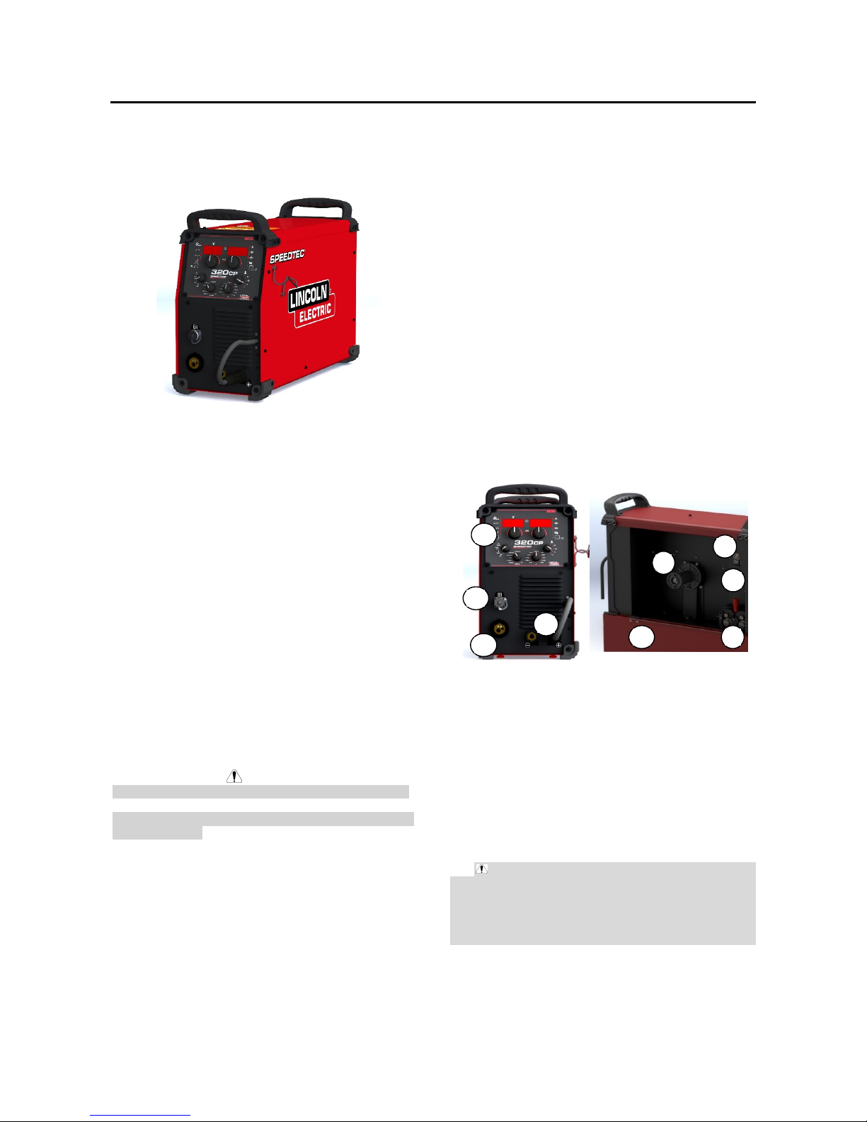
STARTING UP
The power source is composed with :
1 - Front panel display
2 - European plug for torch
3 - Additional plug for 2 potentiometers torch
4 - Plug for ground cable and polarity inversion
5 - Protection door for wire feeder section
6 - Spool axle, shaft, axle nut
7 - Gas purge button
8 - Cold wire feeding button
9 - Wire driver
Input Supply Connection
WARNING
Only a qualified electrician can connect the welding
machine to the supply network. Installation the outlet plug
to power lead and connecting the welding machine had to
be made in accordance with the appropriate National
Electrical Code and local regulations.
Check the input voltage, phase, and frequency supplied
to this machine before turning it on. Verify the connection
of grounding wires from the machine to the input source.
SPEEDTEC 320 CP can only be connected to a mating
grounded receptacle.
6
5
7
8
9
1
4
2
3
English 6 English
Input voltages is 3x400V 50/60Hz. For more information
about input supply refer to the technical specification
section of this manual and to the rating plate of the
machine.
Make sure that the amount of mains power
available from the input supply is adequate for
normal operation of the machine. The type of
protection and cable sizes are indicated in the
technical specification section of this manual.
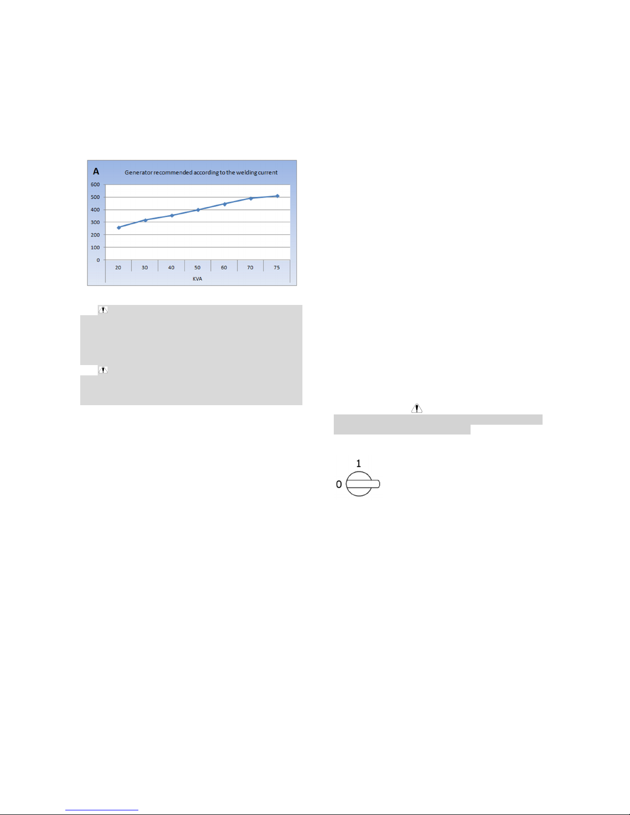
WARNING
The welding machine can be supplied from a power
generator of output power at least 30% larger than input
power of the welding machine.
See "Technical Specifications" chapter.
WARNING
When powering welder from a generator be sure to turn
off welding machine first, before generator is shut down,
in order to prevent damage to welding machine!
To set up the wire:
Turn the power source off.
Open the door of the wire-feeder unit [5] and ensure that it
can not fall.
Unscrew the spool axle nut. [6].
Insert the spool of wire on the axis. Make sure that the
locating pin of the shaft [6] is properly located into the reel
locator.
Screw the spool nut [6] back on the shaft, turning it in the
direction shown by the arrow.
Lower the lever of wire driver [9] in order to release the
rollers.
Take the end of the wire of the spool and cut the distorted
end piece.
Straighten the first 15 centimeters of wire.
Insert the wire via the inlet wire-guide of the plate.
Lower the rollers [9] and raise the lever in order to
immobilise it.
Adjust the pressure of the rollers on the wire to the correct
tension.
Wire feed
The wire feeding button (8) feeds the wire into the torch.
The wire feeds over 1s at minimum speed and the speed
increases gradually until the set wire speed is reached, but
is limited to 12 m/min. The settings may be change at any
time; the power source displays the speed.
To feed the wire through the torch. Maintain the wire
feeding button (8).
Wire speed can be adjusted with the button on front panel.
To full the gas line or adjust the gas flow. Push the gas
bleed button (7).
WIRE DRIVER WEAR PART
The wearing parts of the wire driver, whose role is to
guide and advance the welding wire, must be adapted
to the type and diameter of the welding wire used. On
the other hand, their wear may affect the welding
results. Is necessary to replace them.
Connection of the torch
THE MIG WELDING TORCH IS CONNECTED TO
THE FRONT OF THE POWER SOURCE, AFTER
ENSURING IT HAS BEEN PROPERLY OUTFITTED
WITH THE WEAR PARTS CORRESPONDING TO
THE WIRE USED FOR WELDING.
For this purpose, please refer to the torch instructions.
Gas inlet connection
The gas inlet is positioned at the rear of the power
source. Simply connect it to the pressure-regulator
outlet of the gas cylinder.
Place the gas cylinder on the trolley at the rear of the
power source and fasten the bottle using the strap.
Open the cylinder valve slightly to allow existing
impurities to escape and then reclose it.
Mount the pressure regulator/flowmeter.
Open the gas cylinder.
During welding, the gas flow rate should be between
10 and 20l/min.
WARNING
Be sure that the gas cylinder is properly secured on the
trolley by attaching the safety strap.
SWITCH ON
The main switch is located at the rear
of the power source. Flip this switch
to turn the machine on.
Note:This switch must never be flipped
during welding.
At each start-up, the power source
displays the software version and
recognized power.
 Loading...