

Page 1
IM533
RETURN TO MAIN MENU
Safety Depends on You
Lincoln arc welding and cutting
equipment is designed and built
with safety in mind. However, your
overall safety can be increased by
proper installation ... and thoughtful operation on your part.
NOT INSTALL, OPERATE OR
REPAIR THIS EQUIPMENT
WITHOUT READING THIS
MANUAL AND THE SAFETY
PRECAUTIONS CONTAINED
THROUGHOUT.
importantly, think before you act
and be careful.
And, most
DO
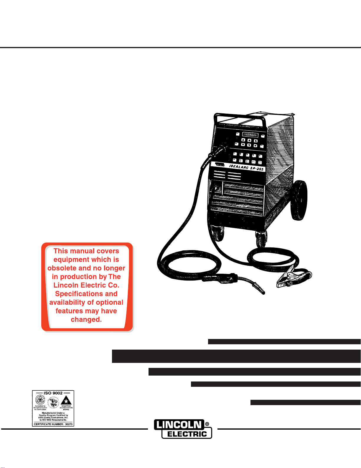
IDEALARC SP-255
For use with machine Code Numbers
10164, 10165
June, 1998
World's Leader in Welding and Cutting Products Premier Manufacturer of Industrial Motors
OPERATOR’S MANUAL
• Sales and Service through Subsidiaries and Distributors Worldwide •
Cleveland, Ohio 44117-1199 U.S.A. TEL: 216.481.8100 FAX: 216.486.1751 WEB SITE: www.lincolnelectric.com
Page 2
i
SAFETY
i
WARNING
CALIFORNIA PROPOSITION 65 WARNINGS
Diesel engine exhaust and some of its constituents
are known to the State of California to cause cancer, birth defects, and other reproductive harm.
The Above For Diesel Engines
ARC WELDING CAN BE HAZARDOUS. PROTECT YOURSELF AND OTHERS FROM POSSIBLE SERIOUS INJURY OR DEATH.
KEEP CHILDREN AWAY. PACEMAKER WEARERS SHOULD CONSULT WITH THEIR DOCTOR BEFORE OPERATING.
Read and understand the following safety highlights. For additional safety information, it is strongly recommended that you
purchase a copy of “Safety in Welding & Cutting - ANSI Standard Z49.1” from the American Welding Society, P.O. Box
351040, Miami, Florida 33135 or CSA Standard W117.2-1974. A Free copy of “Arc Welding Safety” booklet E205 is available
from the Lincoln Electric Company, 22801 St. Clair Avenue, Cleveland, Ohio 44117-1199.
BE SURE THAT ALL INSTALLATION, OPERATION, MAINTENANCE AND REPAIR PROCEDURES ARE
PERFORMED ONLY BY QUALIFIED INDIVIDUALS.
The engine exhaust from this product contains
chemicals known to the State of California to cause
cancer, birth defects, or other reproductive harm.
The Above For Gasoline Engines
FOR ENGINE
powered equipment.
1.a. Turn the engine off before troubleshooting and maintenance
work unless the maintenance work requires it to be running.
____________________________________________________
1.b. Operate engines in open, well-ventilated
areas or vent the engine exhaust fumes
outdoors.
____________________________________________________
1.c. Do not add the fuel near an open flame
welding arc or when the engine is running.
Stop the engine and allow it to cool before
refueling to prevent spilled fuel from vaporizing on contact with hot engine parts and
igniting. Do not spill fuel when filling tank. If
fuel is spilled, wipe it up and do not start
engine until fumes have been eliminated.
____________________________________________________
1.d. Keep all equipment safety guards, covers and devices in
position and in good repair.Keep hands, hair, clothing and
tools away from V-belts, gears, fans and all other moving
parts when starting, operating or repairing equipment.
____________________________________________________
1.e. In some cases it may be necessary to remove safety
guards to perform required maintenance. Remove
guards only when necessary and replace them when the
maintenance requiring their removal is complete.
Always use the greatest care when working near moving
parts.
___________________________________________________
1.f. Do not put your hands near the engine fan.
Do not attempt to override the governor or
idler by pushing on the throttle control rods
while the engine is running.
1.h. To avoid scalding, do not remove the
radiator pressure cap when the engine is
hot.
ELECTRIC AND
MAGNETIC FIELDS
may be dangerous
2.a. Electric current flowing through any conductor causes
localized Electric and Magnetic Fields (EMF). Welding
current creates EMF fields around welding cables and
welding machines
2.b. EMF fields may interfere with some pacemakers, and
welders having a pacemaker should consult their physician
before welding.
2.c. Exposure to EMF fields in welding may have other health
effects which are now not known.
2.d. All welders should use the following procedures in order to
minimize exposure to EMF fields from the welding circuit:
2.d.1.
Route the electrode and work cables together - Secure
them with tape when possible.
2.d.2. Never coil the electrode lead around your body.
2.d.3. Do not place your body between the electrode and
work cables. If the electrode cable is on your right
side, the work cable should also be on your right side.
___________________________________________________
1.g. To prevent accidentally starting gasoline engines while
turning the engine or welding generator during maintenance
work, disconnect the spark plug wires, distributor cap or
magneto wire as appropriate.
2.d.4. Connect the work cable to the workpiece as close as
possible to the area being welded.
2.d.5. Do not work next to welding power source.
Mar ‘95
Page 3

ii
SAFETY
ii
ELECTRIC SHOCK can
kill.
3.a. The electrode and work (or ground) circuits
are electrically “hot” when the welder is on.
Do not touch these “hot” parts with your bare
skin or wet clothing. Wear dry, hole-free
gloves to insulate hands.
3.b. Insulate yourself from work and ground using dry insulation.
Make certain the insulation is large enough to cover your full
area of physical contact with work and ground.
In addition to the normal safety precautions, if welding
must be performed under electrically hazardous
conditions (in damp locations or while wearing wet
clothing; on metal structures such as floors, gratings or
scaffolds; when in cramped positions such as sitting,
kneeling or lying, if there is a high risk of unavoidable or
accidental contact with the workpiece or ground) use
the following equipment:
• Semiautomatic DC Constant Voltage (Wire) Welder.
• DC Manual (Stick) Welder.
• AC Welder with Reduced Voltage Control.
3.c. In semiautomatic or automatic wire welding, the electrode,
electrode reel, welding head, nozzle or semiautomatic
welding gun are also electrically “hot”.
3.d. Always be sure the work cable makes a good electrical
connection with the metal being welded. The connection
should be as close as possible to the area being welded.
3.e. Ground the work or metal to be welded to a good electrical
(earth) ground.
ARC RAYS can burn.
4.a. Use a shield with the proper filter and cover
plates to protect your eyes from sparks and
the rays of the arc when welding or observing
open arc welding. Headshield and filter lens
should conform to ANSI Z87. I standards.
4.b. Use suitable clothing made from durable flame-resistant
material to protect your skin and that of your helpers from
the arc rays.
4.c. Protect other nearby personnel with suitable, non-flammable
screening and/or warn them not to watch the arc nor expose
themselves to the arc rays or to hot spatter or metal.
FUMES AND GASES
can be dangerous.
5.a. Welding may produce fumes and gases
hazardous to health. Avoid breathing these
fumes and gases.When welding, keep
your head out of the fume. Use enough
ventilation and/or exhaust at the arc to keep
fumes and gases away from the breathing zone. When
welding with electrodes which require special
ventilation such as stainless or hard facing (see
instructions on container or MSDS) or on lead or
cadmium plated steel and other metals or coatings
which produce highly toxic fumes, keep exposure as
low as possible and below Threshold Limit Values (TLV)
using local exhaust or mechanical ventilation. In
confined spaces or in some circumstances, outdoors, a
respirator may be required. Additional precautions are
also required when welding on galvanized steel.
3.f.
Maintain the electrode holder, work clamp, welding cable and
welding machine in good, safe operating condition. Replace
damaged insulation.
3.g. Never dip the electrode in water for cooling.
3.h. Never simultaneously touch electrically “hot” parts of
electrode holders connected to two welders because voltage
between the two can be the total of the open circuit voltage
of both welders.
3.i. When working above floor level, use a safety belt to protect
yourself from a fall should you get a shock.
3.j. Also see Items 6.c. and 8.
5.b.
Do not weld in locations near chlorinated hydrocarbon
coming from degreasing, cleaning or spraying operations.
The heat and rays of the arc can react with solvent vapors
form phosgene, a highly toxic gas, and other irritating
products.
5.c. Shielding gases used for arc welding can displace air and
cause injury or death. Always use enough ventilation,
especially in confined areas, to insure breathing air is safe.
5.d. Read and understand the manufacturer’s instructions for this
equipment and the consumables to be used, including the
material safety data sheet (MSDS) and follow your
employer’s safety practices. MSDS forms are available from
your welding distributor or from the manufacturer.
5.e. Also see item 1.b.
Mar ‘95
vapors
to
Page 4
iii
SAFETY
iii
WELDING SPARKS can
cause fire or explosion.
6.a.
Remove fire hazards from the welding area.
If this is not possible, cover them to prevent
the welding sparks from starting a fire.
materials from welding can easily go through small cracks
and openings to adjacent areas. Avoid welding near
hydraulic lines. Have a fire extinguisher readily available.
6.b. Where compressed gases are to be used at the job site,
special precautions should be used to prevent hazardous
situations. Refer to “Safety in Welding and Cutting” (ANSI
Standard Z49.1) and the operating information for the
equipment being used.
6.c. When not welding, make certain no part of the electrode
circuit is touching the work or ground. Accidental contact
can cause overheating and create a fire hazard.
6.d. Do not heat, cut or weld tanks, drums or containers until the
proper steps have been taken to insure that such procedures
will not cause flammable or toxic vapors from substances
inside. They can cause an explosion even
been “cleaned”. For information, purchase “Recommended
Safe Practices for the
Containers and Piping That Have Held Hazardous
Substances”, AWS F4.1 from the American Welding Society
(see address above).
6.e. Vent hollow castings or containers before heating, cutting or
welding. They may explode.
Sparks and spatter are thrown from the welding arc. Wear oil
6.f.
free protective garments such as leather gloves, heavy shirt,
cuffless trousers, high shoes and a cap over your hair. Wear
ear plugs when welding out of position or in confined places.
Always wear safety glasses with side shields when in a
welding area.
6.g. Connect the work cable to the work as close to the welding
area as practical. Work cables connected to the building
framework or other locations away from the welding area
increase the possibility of the welding current passing
through lifting chains, crane cables or other alternate circuits. This can create fire hazards or overheat lifting chains
or cables until they fail.
6.h. Also see item 1.c.
Remember that welding sparks and hot
though
they have
Preparation
for Welding and Cutting of
CYLINDER may explode
if damaged.
7.a. Use only compressed gas cylinders
containing the correct shielding gas for the
process used and properly operating
regulators designed for the gas and
pressure used. All hoses, fittings, etc. should be suitable for
the application and maintained in good condition.
7.b. Always keep cylinders in an upright position securely
chained to an undercarriage or fixed support.
7.c. Cylinders should be located:
• Away from areas where they may be struck or subjected to
physical damage.
• A safe distance from arc welding or cutting operations and
any other source of heat, sparks, or flame.
7.d. Never allow the electrode, electrode holder or any other
electrically “hot” parts to touch a cylinder.
7.e. Keep your head and face away from the cylinder valve outlet
when opening the cylinder valve.
7.f. Valve protection caps should always be in place and hand
tight except when the cylinder is in use or connected for
use.
7.g. Read and follow the instructions on compressed gas
cylinders, associated equipment, and CGA publication P-l,
“Precautions for Safe Handling of Compressed Gases in
Cylinders,” available from the Compressed Gas Association
1235 Jefferson Davis Highway, Arlington, VA 22202.
FOR ELECTRICALLY
powered equipment.
8.a. Turn off input power using the disconnect
switch at the fuse box before working on
the equipment.
8.b. Install equipment in accordance with the U.S. National
Electrical Code, all local codes and the manufacturer’s
recommendations.
8.c. Ground the equipment in accordance with the U.S. National
Electrical Code and the manufacturer’s recommendations.
Mar ‘95
Page 5

iv
SAFETY
iv
PRÉCAUTIONS DE SÛRETÉ
Pour
votre propre protection lire et observer toutes les instructions
et les précautions de sûreté specifiques qui parraissent dans ce
manuel aussi bien que les précautions de sûreté générales suivantes:
Sûreté Pour Soudage A L’Arc
1. Protegez-vous contre la secousse électrique:
a. Les circuits à l’électrode et à la piéce sont sous tension
quand la machine à souder est en marche. Eviter toujours
tout contact entre les parties sous tension et la peau nue
ou les vétements mouillés. Porter des gants secs et sans
trous pour isoler les mains.
b. Faire trés attention de bien s’isoler de la masse quand on
soude dans des endroits humides, ou sur un plancher
metallique ou des grilles metalliques, principalement dans
les positions assis ou couché pour lesquelles une grande
partie du corps peut être en contact avec la masse.
c. Maintenir le porte-électrode, la pince de masse, le câble
de soudage et la machine à souder en bon et sûr état
defonctionnement.
d.Ne jamais plonger le porte-électrode dans l’eau pour le
refroidir.
e. Ne jamais toucher simultanément les parties sous tension
des porte-électrodes connectés à deux machines à souder
parce que la tension entre les deux pinces peut être le
total de la tension à vide des deux machines.
f. Si on utilise la machine à souder comme une source de
courant pour soudage semi-automatique, ces precautions
pour le porte-électrode s’applicuent aussi au pistolet de
soudage.
zones où l’on pique le laitier.
6. Eloigner les matériaux inflammables ou les recouvrir afin de
prévenir tout risque d’incendie dû aux étincelles.
7. Quand on ne soud
la masse. Un court-circuit accidental peut provoquer un
échauffement et un risque d’incendie.
8. S’assurer que la masse est connectée le plus prés possible
de la zone de travail qu’il est pratique de le faire. Si on place
la masse sur la charpente de la construction ou d’autres
endroits éloignés de la zone de travail, on augmente le risque
de voir passer le courant de soudage par les chaines de levage, câbles de grue, ou autres circuits. Cela peut provoquer
des risques d’incendie ou d’echauffement des chaines et des
câbles jusqu’à ce qu’ils se rompent.
9. Assurer une ventilation suffisante dans la zone de soudage.
Ceci est particuliérement important pour le soudage de tôles
galvanisées plombées, ou cadmiées ou tout autre métal qui
produit des fumeés toxiques.
10. Ne pas souder en présence de vapeurs de chlore provenant
d’opérations de dégraissage, nettoyage ou pistolage. La
chaleur ou les rayons de l’arc peuvent réagir avec les vapeurs
du solvant pour produire du phosgéne (gas fortement toxique)
ou autres produits irritants.
11. Pour obtenir de plus amples renseignements sur la sûreté,
voir le code “Code for safety in welding and cutting” CSA
Standard W 117.2-1974.
e pas, poser la pince à une endroit isolé de
2. Dans le cas de travail au dessus du niveau du sol, se protéger
contre les chutes dans le cas ou on recoit un choc. Ne jamais
enrouler le câble-électrode autour de n’importe quelle partie
du corps.
3. Un coup d’arc peut être plus sévère qu’un coup de soliel,
donc:
a. Utiliser un bon masque avec un verre filtrant approprié
ainsi qu’un verre blanc afin de se protéger les yeux du rayonnement de l’arc et des projections quand on soude ou
quand on regarde l’arc.
b. Porter des vêtements convenables afin de protéger la
peau de soudeur et des aides contre le rayonnement de
l‘arc.
c. Protéger l’autre personnel travaillant à proximité au
soudage à l’aide d’écrans appropriés et non-inflammables.
4. Des gouttes de laitier en fusion sont émises de l’arc de
soudage. Se protéger avec des vêtements de protection libres
de l’huile, tels que les gants en cuir, chemise épaisse, pantalons sans revers, et chaussures montantes.
5. Toujours porter des lunettes de sécurité dans la zone de
soudage. Utiliser des lunettes avec écrans lateraux dans les
PRÉCAUTIONS DE SÛRETÉ POUR
LES MACHINES À SOUDER À
TRANSFORMATEUR ET À
REDRESSEUR
1. Relier à la terre le chassis du poste conformement au code de
l’électricité et aux recommendations du fabricant. Le dispositif
de montage ou la piece à souder doit être branché à une
bonne mise à la terre.
2. Autant que possible, I’installation et l’entretien du poste seront
effectués par un électricien qualifié.
3. Avant de faires des travaux à l’interieur de poste, la debrancher à l’interrupteur à la boite de fusibles.
4. Garder tous les couvercles et dispositifs de sûreté à leur
place.
Mar. ‘93
Page 6

for selecting a QUALITY product by Lincoln Electric. We want you
Thank You
to take pride in operating this Lincoln Electric Company product
••• as much pride as we have in bringing this product to you!
Please Examine Carton and Equipment For Damage Immediately
When this equipment is shipped, title passes to the purchaser upon receipt by the carrier. Consequently, Claims
for material damaged in shipment must be made by the purchaser against the transportation company at the
time the shipment is received.
Please record your equipment identification information below for future reference. This information can be
found on your machine nameplate.
Model Name & Number _____________________________________
Code & Serial Number _____________________________________
Date of Purchase _____________________________________
Whenever you request replacement parts for or information on this equipment always supply the information
you have recorded above.
vv
Read this Operators Manual completely before attempting to use this equipment. Save this manual and keep it
handy for quick reference. Pay particular attention to the safety instructions we have provided for your protection.
The level of seriousness to be applied to each is explained below:
WARNING
This statement appears where the information must be followed exactly to avoid serious personal injury or
loss of life.
CAUTION
This statement appears where the information must be followed to avoid minor personal injury or damage to
this equipment.
Page 7

MASTER TABLE OF CONTENTS FOR ALL SECTIONS
Page
Installation .......................................................................................................Section A
Technical Specifications ........................................................................................A-1
Safety Precautions.................................................................................................A-2
Uncrating the SP-255 ............................................................................................A-2
Location .................................................................................................................A-2
Input Power, Grounding and Connection Diagrams ..............................................A-2
Output Polarity Connections..................................................................................A-3
Gun and Cable Installation ....................................................................................A-3
Shielding Gas .......................................................................................................A-4
Operation .........................................................................................................Section B
Safety Precautions ................................................................................................B-1
Product Description ...............................................................................................B-2
Recommended Processes and Equipment ...........................................................B-2
Welding Capability.................................................................................................B-2
Limitations..............................................................................................................B-2
Description of Controls and Keys ..........................................................................B-2
Gun Switches.......................................................................................................B-10
Wire Drive Roll.....................................................................................................B-10
Procedure for Changing Drive Roll......................................................................B-10
Wire Reel Loading ...............................................................................................B-10
Mounting of 10 to 44 lbs. Spools .........................................................................B-11
To Start the Welder..............................................................................................B-11
Feeding Electrode................................................................................................B-11
Idle Roll Pressure Setting ....................................................................................B-11
Making a Auto Mode Weld...................................................................................B-12
Spot Weld Mode ..................................................................................................B-13
Stitch Weld Mode.................................................................................................B-13
Avoiding Wire Feeding Problems ........................................................................B-13
Fan Control..........................................................................................................B-13
Input Line Voltage Protection...............................................................................B-13
Wire Feed Overload Protection ...........................................................................B-13
Welding Thermal Overload Protection.................................................................B-14
Overcurrent Protection.........................................................................................B-14
Explanation of Prompting and Error Messages ...................................................B-14
vi
Accessories.....................................................................................................Section C
Drive Roll Kits........................................................................................................C-1
Aluminum Feeding Kit (optional K673-1)...............................................................C-1
8" Spool Adapter (K468)........................................................................................C-1
Dual Cylinder Mounting Kit (K671-1).....................................................................C-1
Spool Gun Description...........................................................................................C-1
Spool Gun Adapter Kit (optional K672-1) ..............................................................C-1
Making a Weld with the Spool Gun Adapter Kit and Spool Gun Installed .............C-1
(continued)
APR96 IDEALARC SP-255
Page 8

vii
MASTER TABLE OF CONTENTS FOR ALL SECTIONS
Page
Maintenance ....................................................................................................Section D
Safety Precautions ................................................................................................D-1
General Maintenance ............................................................................................D-1
Drive Rolls and Guide Tubes.................................................................................D-1
Gun Tubes and Nozzles........................................................................................D-1
Cable Cleaning......................................................................................................D-1
Contact Tip and Gas Nozzle Installation ...............................................................D-1
Liner Removal and Replacement ..........................................................................D-2
Gun Handle Disassembly......................................................................................D-3
Magnum 250SP Gun Parts and Accessories ........................................................D-3
Troubleshooting..............................................................................................Section E
How To Use Troubleshooting Guide......................................................................E-1
Troubleshooting Guide ..........................................................................................E-2
Wiring Diagrams..............................................................................................Section F
Wiring Diagram L9688 (208/230V) ........................................................................F-1
Wiring Diagram L9689 (230/460/575V) .................................................................F-2
Dimension Print M16352........................................................................................F-3
Parts Lists........................................................................................................Appendix
IDEALARC SP-255
Page 9

INSTALLATION
TECHNICAL SPECIFICATIONS – IDEALARC®SP-255
INPUT – SINGLE PHASE ONLY
Standard Voltage/Frequency Input Current (@ Max Rated Output)
208/230/60 Hz 53/49 Amps
230/460/575 Hz 50/25/20 Amps
RATED OUTPUT
Duty
Cycle Amps Volts at Rated Amperes
35% 250 Amps 26 Volts
60% 200 Amps 28 Volts
100% 145 Amps 26 Volts
OUTPUT
A-1
Welding
Current Range Maximum Open Circuit Voltage Wire Speed Range
30-250 Amps 40 Volts 50-600 IMP (1.27-15.2 m/min)
RECOMMENDED INPUT CABLE AND FUSE SIZES
75C Copper Wire 75C Copper Wire
in Conduit in Conduit
Input Fuse or Input Ampere AWG (IEC) AWG (IEC)
Voltage/ Breaker Size Rating on Sizes Sizes
Frequency (Super Lag) Nameplate For lengths For lengths Ground Wire
up to 100 ft. exceeding 100 ft.
208 60 53 8 (10 mm2) 6 (16 mm2) #10 (6 mm2)
230 60 50 10 (6 mm2) 8 (10 mm2) #10 (6 mm2)
460 30 25 14 (2.5 mm2) 12 (4 mm2) #10 (6 mm2)
575 25 20 14 (2.5 mm
2
) 12 (4 mm2) #10 (6 mm2)
PHYSICAL DIMENSIONS
Height Width Depth Weight
28.2 in 18.8 in 40.1 in 222 Ibs
719 mm 480 mm 1019 mm 101 kg
OPERATING TEMPERATURE STORAGE TEMPERATURE
-20° C TO 40°C ±40°C
AUG 95 IDEALARC SP-255
Page 10
A-2
INSTALLATION
Read entire Installation section before starting
installation.
SAFETY PRECAUTIONS
WARNING
ELECTRIC SHOCK can kill.
• Only qualified personnel should perform
this installation.
• Only personnel that have read and understood the SP-255 Operating Manual should
install and operate this equipment.
• Machine must be plugged into a receptacle
which is grounded per any national, local
or other applicable electrical codes.
• Turn the power switch on the SP-255 “off”
before connecting or disconnecting gun
and cable, output cables or other equipment.
UNCRATING THE SP-255
1. Before starting the installation, check with the local
power company if there is any question about
whether your power supply is adequate for the voltage, amperes, phase, and frequency specified on
the welder nameplate. Also, be sure the planned
installation will meet the U.S. National Electrical
Code and local code requirements. This welder
may be operated from a single phase line or from
one phase of a two or three phase line.
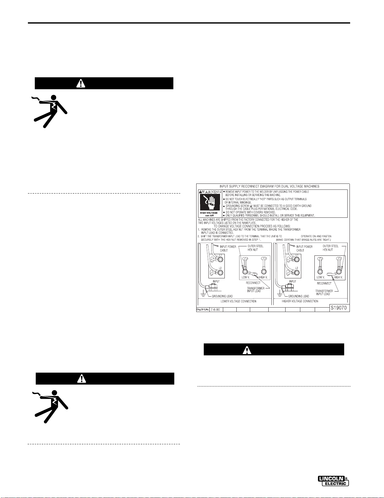
2. Models that have multiple input voltages specified
on the nameplate (e.g., 208/230) are shipped connected for the higher voltage. If the welder is to be
operated on lower voltage, it must be reconnected
according to the instructions on the inside of the
removable panel near the top left side of the rear
panel. These instructions are repeated below:
Remove the staples from the bottom edge of the carton and lift off. Cut the tape securing the two rear
wheels to the wooden shipping pallet. Using a 1/2 inch
(or 13 mm) wrench or socket, remove the two screws
which attach the pallet to the bottom of the SP-255.
LOCATION
Locate the welder in a dry location where there is free
circulation of clean air into the louvers in the back and
out the front. A location that minimizes the amount of
smoke and dirt drawn into the rear louvers reduces
the chance of dirt accumulation that can block air passages and cause overheating.
INPUT POWER AND GROUNDING
CONNECTIONS
WARNING
ELECTRIC SHOCK can kill.
• Do not touch electrically live parts such as
output terminals or internal wiring
•
All input power must be electrically disconnected before
proceeding.
WARNING
Make certain that the input power is electrically
disconnected before removing the screw that
holds the removable rear panel in place.
3. The 208/230 volt 60 Hz model SP-255 is shipped
with a 10 ft. (3.0 m) input cable and plug connected
to the welder. A matching receptacle is supplied
with the machine. Mount the receptacle in a suitable location using the screws provided. Be sure it
can be reached by the plug on the input cable
attached to the welder. Mount with the grounding
terminal at the top to allow the power cable to hang
down without bending.
IDEALARC SP-255 OCT94
Page 11
INSTALLATION
A-3
The 230/460/575 volt 60 Hz model is not equipped
with a plug, input cable or receptacle.
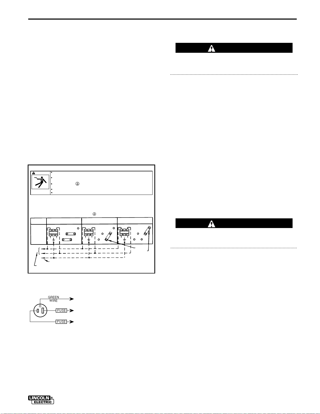
4. Using the following instructions have a qualified
electrician connect the receptacle or cable to the
input power lines and the system ground per the
U.S. National Electrical Code and any applicable
local codes. See the “Technical Specifications”
page at the beginning of this chapter for proper
wire sizes. For long runs over 100 feet (30 m), larger copper wires should be used. Fuse the two hot
lines with super lag type fuses as shown in the following diagram. The center contact in the receptacle is for the grounding connection. A green wire in
the input cable connects this contact to the frame
of the welder.
This ensures proper grounding of the welder frame
when the welder plug is inserted into the
receptacle.
SINGLE PHASE INPUT SUPPLY RECONNECT DIAGRAM FOR 230/460/575 60 HZ MACHINES
WARNING
HIGH VOLTAGE
can kill
1. ALL MACHINES ARE SHIPPED FROM THE FACTORY CONNECTED FOR THE HIGHEST NAMEPLATED SINGLE PHASE
INPUT VOLTAGE. TO CHANGE CONNECTIONS FOR A DIFFERENT INPUT VOLTAGE. RECONNECT BOTH COPPER
JUMPERS PER DIAGRAM BELOW. ALWAYS CONNECT JUMPERS BETWEEN OUTER STEEL NUT AND
INNER BRASS NUT ON TERMINAL STUDS.
2. CONNECT THE INPUT POWER TO THE INPUT TERMINAL BLOCK, L1 AND L2 AT THE UPPER LEFT CORNER OF
THE PANEL. TORQUE TO 16 IN-LBS.
3. CONNECT A GROUNDING LEAD TO THE GROUND STUD ON THE MACHINE NEAR THE INPUT TERMINAL BLOCK.
SINGLE PHASE
VOLTAGE
JUMPER
CONNECTION
DIAGRAMS
TURN THE INPUT POWER OFF AT THE DISCONNECT SWITCH BEFORE INSTALLING
OR SERVICING THIS MACHINE.
DO NOT TOUCH ELECTRICALLY "HOT" PARTS SUCH AS OUTPUT TERMINALS
OR INTERNAL WINDINGS.
GROUNDING SCREW
NATIONAL ELECTRICAL CODE.
DO NOT OPERATE WITH COVERS REMOVED.
ONLY QUALIFIED PERSONNEL SHOULD INSTALL OR SERVICE THIS EQUIPMENT.
230V / 60HZ. 460V. / 60HZ.
L1
L2
1
TO GROUND PER NATIONAL ELECTRICAL CODE
SINGLE PHASE INPUT POWER SUPPLY LINES
MUST BE CONNECTED TO A GOOD EARTH GROUND PER
L1
L2
5
2
4
3
4
1
3
CONNECT TO A SYSTEM GROUNDING WIRE. SEE THE UNITED STATES
NATIONAL. ELECTRICAL CODE
AND/OR LOCAL CODES FOR OTHER
DETAILS AND MEANS FOR PROPER
GROUNDING.
CONNECT TO HOT WIRES OF A
THREE-WIRE, SINGLE PHASE SYSTEM OR TO ONE PHASE OF A TWO
OR THREE PHASE SYSTEM.
575V. / 60HZ.
L1
5
2
L2
4
1
BOTH
JUMPERS
5
2
3
S21531-1
OUTPUT POLARITY CONNECTION
WARNING
Turn the welder power switch off before changing
output connection.
The welder, as shipped from the factory, is connected
for electrode positive (+) polarity. This is the normal
polarity for GMA welding.
If negative (–) polarity is required, interchange the
connections of the two cables located in the wire drive
compartment near the front panel. The electrode
cable, which is attached to the wire drive, is to be connected to the negative (–) labeled terminal and the
work lead, which is attached to the work clamp, is to
be connected to the positive (+) labeled terminal.
GUN AND CABLE INSTALLATION
The Magnum™ 250SP gun and cable provided with
the SP-255 is factory installed with a liner for .035.045" (0.9-1.2 mm) electrode and an .035" (0.9 mm)
contact tip. Install the .045 tip (also provided) if this
wire size is being used. For other wire sizes, see Gun
and Cable Maintenance.
WARNING
Turn the welder power switch off before installing
gun and cable.
1. Lay the cable out straight.
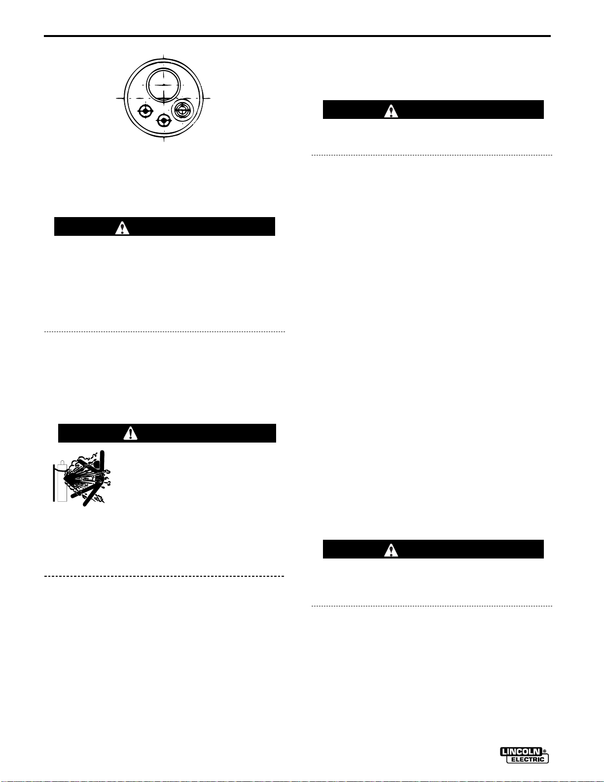
2. Make sure all pins on the gun cable connector are
aligned with the proper mating sockets on the front
panel gun connector and then join the connectors
and tighten the hand nut on the gun cable connector.
NOTE: If a gun and cable other than the Magnum
250SP is to be used, it must conform to standard
European-style connector (Magnum Fast-Mate™)
specifications. See diagram below.
IDEALARC SP-255
Page 12
A-4
INSTALLATION
Gun - END VIEW
However, the thumbswitch functions available on
the Magnum 250SP gun will only be operable from
the front panel keypad. The gun trigger switch must
be capable of switching 5 milliamps at 15 volts
DC– resistive.
3. Stand to one side away from the outlet and open
the cylinder valve for an instant. This blows away
any dust or dirt which may have accumulated in the
valve outlet.
WARNING
Be sure to keep your face away from the valve
outlet when “cracking” the valve.
4. Inspect the regulator for damaged threads, dirt,
dust, oil or grease. Remove dust and dirt with a
clean cloth.
CAUTION
The gun trigger switch connected to the gun trigger control cable must be a normally open,
momentary switch. The terminals of the switch
must be insulated from the welding circuit.
Improper operation of or damage to the SP-255
might result if this switch is common to an electrical circuit other than the SP-255 trigger circuit.
SHIELDING GAS
(For Gas Metal Arc Welding Processes)
Customer must provide cylinder of appropriate type
shielding gas for the process being used.
WARNING
CYLINDER may explode if
damaged.
Gas under pressure is explosive.
Always keep gas cylinders in an
upright position and always keep
chained to undercarriage or stationary support.
See American national Standard Z49.1, “Safety in
Welding and Cutting” published by the American
Welding Society.
1. Set gas cylinder in rear platform of SP-255. Hook
chain in place to secure cylinder to rear of welder.
DO NOT USE THE REGULATOR IF OIL,
GREASE OR DAMAGE IS PRESENT! Have an
authorized repair station clean the regulator or
repair any damage.
5. Attach the flow regulator to the cylinder valve and
tighten the union nut(s) securely with a wrench.
NOTE: If connecting to 100% CO
regulator adapter provided between regulator and
cylinder valve. If adapter is equipped with a plastic
washer, be sure it is seated for connection to the
CO
cylinder.
2
6. Attach one end of the inlet gas hose to the outlet
fitting of the flow regulator, the other end to the SP255 rear fitting, and tighten the union nuts securely
with a wrench.
7. Before opening the cylinder valve, turn the regulator adjusting knob counter-clockwise until the
adjusting spring pressure is released.
8. Open the cylinder valve slowly a fraction of a turn.
When the cylinder pressure gauge pointer stops
moving, open the valve fully.
cylinder, insert
2
WARNING
Never stand directly in front of or behind the flow
regulator when opening the cylinder valve. Always
stand to one side.
2. Remove the cylinder cap. Inspect the cylinder
valves for damaged threads, dirt, dust, oil or
grease. Remove dust and dirt with a clean cloth.
DO NOT ATTACH THE REGULATOR IF OIL,
GREASE OR DAMAGE IS PRESENT! Inform your
gas supplier of this condition. Oil or grease in the
presence of high pressure oxygen is explosive.
IDEALARC SP-255 OCT94
9. The flow regulator is adjustable. Set it for the flow
rate recommended for the procedure and process
being used before making the weld.
Page 13
OPERATION
Read entire Operation section before
operating the SP-255.
WARNING
ELECTRIC SHOCK can kill.
• Do not touch electrically live
parts or electrode with skin or
wet clothing. Insulate yourself
from work and ground.
• Always wear dry insulating
gloves.
FUMES AND GASES can be
dangerous.
• Keep your head out of fumes.
• Use ventilation or exhaust to
remove fumes from breathing
zone.
B-1
WELDING SPARKS can
cause fire or explosion.
• Keep flammable material away.
• Do not weld on closed containers.
ARC RAYS can burn eyes
and skin.
• Wear eye, ear and body protection.
Observe all safety information throughout
this manual.
IDEALARC SP-255
Page 14
B-2
OPERATION
PRODUCT DESCRIPTION
The SP-255 is a complete semiautomatic constant
voltage DC arc welding machine built to meet NEMA
specifications. It combines a constant voltage power
source and a constant speed wire feeder with a microcomputer-based controller. This forms an intelligent
welding system that really puts the automatic in semiautomatic. A touch key entry system with audible
feedback, along with a two-line, 32 character alphanumeric display provide user friendly control of the system.
Multilingual display capability allows the SP-255 to
communicate with the user in any of the following languages: English, German, French, Spanish, or
Japanese (Katakana).
RECOMMENDED PROCESSES AND
EQUIPMENT
The SP-255 is recommended for GMA welding
processes using 10 to 44 lb. (4.5 to 20 kg) 2" (51 mm)
I.D. spools or Readi-Reel
(0.6-1.2 mm) solid steel using CO2, ArCO2, or ArO
shielding gas, .035" (0.9 mm) stainless steel using
ArO2or HeArCO2shielding gas, 3/64" (1.2 mm) aluminum using Ar shielding gas, and .045" (1.2 mm)
Outershield
gas, as well as .035" (0.9 mm) and .045" (1.2 mm)
Innershield®self-shielded electrodes.
®
electrodes using CO2or ArCO2shielding
®
coils of .025 through .045
DESCRIPTION OF CONTROLS AND
KEYS
POWER SWITCH
Place the lever in the “ON” position to turn the SP-255
on. When the power is on, the red LED backlighting of
the LCD display will be lit, and the screen will contain
a readable display. The welding setup present when
the power was shut off or disconnected will be
restored when the power is restored.
SETUP KEYS
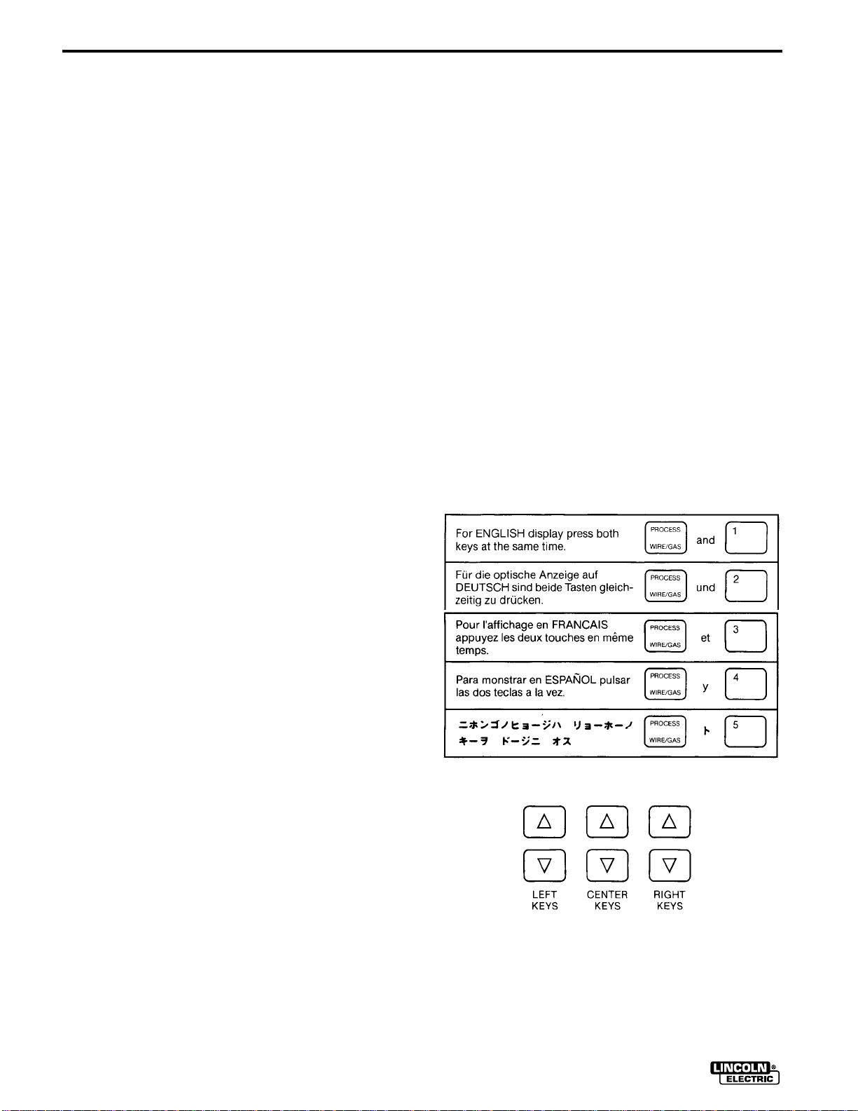
DISPLAY LANGUAGE SELECTION
The SP-255 has multilingual display capability permitting the SP-255 prompts, messages, and other display
information to be in any of five languages: English,
German, French, Spanish, and Japanese (Katakana).
The user may select the chosen language by simultaneously pressing the PROCESS Key and the appropriate Number Key per the instructions given in the
appropriate language on the Keypad Instruction Decal
inside the SP-255 door, also shown below:
2
The SP-255 is factory equipped to feed .035" (0.9
mm) and .045" (1.2 mm) electrodes and includes a
200A, 60% duty cycle rated, 12.5 ft. (3.8 m) GMA gun
and cable assembly equipped for these wire sizes.
The SP-255 is factory equipped with an adjustable
CO
and Argon blend flow regulator. A supply of
2
shielding gas is required for GMAW processes.
WELDING CAPABILITY
The SP-255 is rated at 250 amps @ 26 volts at a 35%
duty cycle on a ten minute basis. It is capable of higher duty cycles at lower output currents.
LIMITATIONS
The SP-255 may not operate as designed if powered
with a portable or in-plant generator.
ARROW KEYS
There are three pairs of arrow keys: left, center, and
right. The up arrow keys increase the selection displayed directly above them. The down arrow keys
decrease the selection displayed directly above them.
All of the arrow keys have a repeat function when they
IDEALARC SP-255
Page 15
OPERATION
are held closed. The left pair will automatically continue to increment or decrement the selection above it at
a slow, steady rate as long as the key is pressed. The
center and right pairs will continue to increment and
decrement the selections above them at a slow rate,
but then the rate will gradually increase until it
becomes very rapid. This allows rapid setting from a
small quantity to a large quantity or vice versa while
maintaining an excellent resolution (i.e., 50 IPM to 600
IPM). However, when the trigger is closed, the
changes will be at a steady, moderate rate to allow for
proper “on the fly” control.
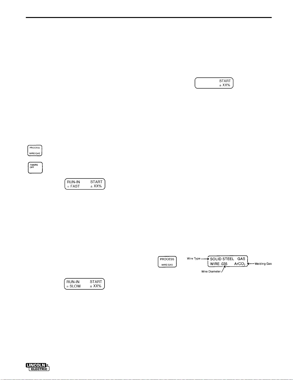
START MODE SELECTIONS
The SP-255 permits selection of Fast/Slow Run-In
wire feed speed as well as adjustment of the start
striking voltage, to optimize arc starting, using the
starting screen display.
The starting screen (see Figures below) is
displayed by pressing and holding both the
PROCESS key and the TIMERS OFF key at
the same time.
B-3
3. Spool Gun Start Mode
If using optional spool gun mode (see “Making
a Weld with the Spool Gun” in Accessories section), the RUN-IN portion of the starting screen
is not functional and will not be displayed. The
START voltage is adjusted as described above
(Figure 3).
FIGURE 3
The starting screen is exited by pressing any
key on the keypad except TIMERS OFF, IPMVOLTS or any Arrow key. Closing Gun Trigger
will also not clear the starting screen.
NOTE: It is not necessary to repeat the above
procedure each time the unit is powered up.
That is, the unit will remember the start mode
settings from the previous power down and
return you to that same state upon your next
power up. thus, you need only perform the
above procedure when you want to change the
start mode settings.
FIGURE 1
1. Run-In Speed
The SP-255 is factory set for FAST run-in
(Figure 1) where the wire feed will accelerate
directly to the preset speed. SLOW run-in will
initially feed at 50 IPM until welding current is
sensed, or for 2 seconds if feeding without
welding (loading wire).
SLOW run-in may be selected using the left
arrow keys which will toggle the starting screen
display to SLOW (Figure 2) or back to FAST
(Figure 1).
FIGURE 2
2. Start Voltage
The START voltage setting (Figure 1 or 2) may
be offset from the factory programmed level
(00%) by up to ±30% above or below programmed level using the right arrow keys, or
from the gun thumbswitch by positioning the
screen cursor beneath the START display using
the IPM-VOLTS key. (see “Gun Switch Keys” in
this section).
When saving to Memory locations 1-5, the start
mode at the time of saving will be saved into
the memory location as well. Thus, the operator
should be aware that when recalling a memorized procedure, he is also recalling particular
start mode which will override any present start
mode setting and remain in effect until either
the mode is changed using the above procedure or until a memorized procedure containing
another start mode is recalled.
PROCESS (WIRE/GAS) KEY
This key is used to display the Wire Type, Wire
Diameter, and Welding Gas. Each combination of wire
and gas dictates a unique relationship between the
wire feed speed and the arc voltage. The SP-255
uses this unique relationship, along with the metal
thickness, to set the proper values of wire feed speed
and arc voltage. Therefore, it is very important that
the wire type, wire diameter, and welding gas on
the display match the actual wire type, wire diameter, and welding gas being used for the weld.
Left arrow keys—set Wire Type
JAN96 IDEALARC SP-255
Page 16
B-4
OPERATION
Center arrow keys—set Wire Diameter
Right arrow keys—set Welding Gas
The following 16 processes are programmed into the
SP-255:
Wire Type Wire Diameter Welding Gas
Solid Steel
Solid Steel
Solid Steel
Solid Steel
Solid Steel
Solid Steel
Solid Steel
Solid Steel
Solid Steel
Stainless
Stainless
Aluminum (5356)
Outershield
Outershield
Innershield
Innershield
®
®
.025 (0.6mm)
.025 (0.6mm)
.030 (0.8mm)
.030 (0.8mm)
.035 (0.9mm)
.035 (0.9mm)
.035 (0.9mm)
.045 (1.2mm)
.045 (1.2mm)
.035 (0.9mm)
.035 (0.9mm)
3/64” (1.2mm)
.045 (1.2mm)
.045 (1.2mm)
.035 (0.9mm)
.045 (1.2mm)
CO
2
ArCO
2
CO
2
ArCO
2
CO
2
ArCO
2
ArO
2
CO
2
ArCO
2
ArO
2
HeArCO
Argon
CO
2
Ar/CO
2
None
None
2
PROCEDURE KEYS
Because design, fabrication, assembly and
welding variables affect the results obtained in
applying recommended procedure information,
the serviceability of a product or assembly is
the responsibility of the builder/user.
available sizes. (NOTE: If the spot or stitch timers are
on, metal thickness is not displayed and, therefore,
the left arrow keys will not function. Also, the left arrow
keys do not function when the trigger is closed. (See
Figures I and 2 following.)
Center arrow keys — Increases (up arrow) or
decreases (down arrow) wire feed speed setting.
Increasing or decreasing wire feed speed will
simultaneously cause an increase or decrease in
the arc voltage and can change the metal thickness setting.
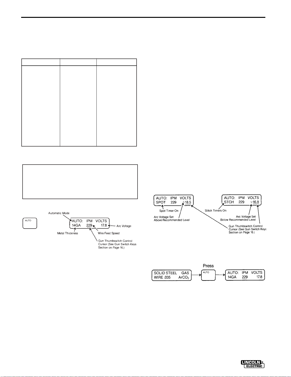
Right arrow keys — Increases (up arrow) or
decreases (down arrow) arc voltage setting. An up
arrow indicator appears below the V in VOLTS if
the arc voltage has been set higher than the recommended value, and a down arrow indicator
appears below the V in VOLTS if the arc voltage is
below the recommended value. No arrow indicates
that you are set to the recommended value. (See
Figures 4 and 5 following.)
Repressing the Auto key resets the wire feed speed
and arc voltage settings to the recommended values
for the metal thickness displayed. (NOTE: If the spot
or stitch timers are on, metal thickness is not displayed and, therefore, the repress function does not
work.)
AUTO KEY
Pressing the Auto Key once places the SP-255 into
the automatic mode of operation. Auto mode provides
automatic setup of the recommended wire feed speed
and arc voltage based on the metal thickness selected
and the process being used. The Auto mode screen
displays metal thickness, set wire feed speed, the set
arc voltage, and a cursor that indicates which parameter, wire feed speed, or arc voltage is being controlled
by the thumbswitch on the SP-255 gun (see Gun
Switches section).
Left arrow keys — Increases (up arrow) or
decreases (down arrow) metal thickness setting.
Increasing or decreasing metal thickness automatically increases or decreases both wire feed speed
and arc voltage simultaneously. See gauge chart
on instruction label on inside of SP-255 door for
Figure 4 Figure 5
TYPICAL AUTO KEY PRESS SEQUENCES
Process screen is being displayed prior to pressing
Auto key. The Auto key is pressed, the Auto screen is
now displayed.
If the unit was in a Manual configuration (see Manual
Key) when the Auto key was pressed, the audio alarm
will beep three times and a message (see below) will
be displayed for 2.5 seconds reminding you that the
process entered into the SP-255 (see Process Key)
must match the wire and gas being used. After the 2.5
second period is over, the Auto screen will be displayed with the same procedure that was in Manual.
IDEALARC SP-255
Page 17

OPERATION
Repressing the Auto Key sets the recommended procedure for the metal thickness displayed.
MANUAL KEY
Permits individual setting of wire feed speed and arc
voltage for manual procedure setup. The manual
screen displays wire feed speed, arc voltage, and a
cursor that indicates which parameter, wire feed
speed, or arc voltage is being controlled by the thumbswitch on the SP-255 gun (see “Gun Switches” in
operation section).
Left arrow keys — Do not function in Manual mode.
B-5
MEMORY KEYS
SAVE KEY
Saves present setup (including process, procedure,
and timer functions, if used) to one of five memories
chosen by pressing the desired memory number key.
When the Save key is pressed, a prompting message
instructing the operator to “PRESS MEMORY 1-5 TO
SAVE SETUP” is displayed. This message will stay on
the display until a memory number key is selected or
one of the other keys, such as Auto, Manual, or
Process, is pressed. If a memory number key is
selected, a message will be displayed for 2.5 seconds
that confirms that the setup was saved to that memory
number (see Key Press Sequence following).
The six arrow keys perform no function when saving a
setup.
NOTE: When a setup is saved to a memory, the previous content of that memory is lost because it is
replaced by the present setup. Removing input power
does not affect setups In memory.
Center arrow keys — Increase (up arrow) or
decrease (down arrow) wire feed speed.
Right arrow keys — Increase (up arrow) or
decrease (down arrow) arc voltage.
If the spot or stitch timers are on it will be indicated in
the bottom left corner of the display. (See Figures 6
and 7 below.)
TYPICAL MANUAL KEY PRESS SEQUENCE
Figure 6 Figure 7
Auto screen is being displayed prior to pressing
Manual key. The Manual key is pressed, the Manual
screen is now displayed. The procedure is the same
that was in Auto.
TYPICAL SAVE KEY PRESS SEQUENCE
Auto screen displayed prior to pressing Save key.
Save key is pressed, and display changes to prompting message. Memory 1 key is pressed, and the display changes to a message that confirms the setup
was saved to memory 1. The message is displayed
for 2.5 seconds, and then the original Auto screen is
displayed.
MEMORY NUMBER KEY
Pressing the desired Memory Number key recalls the
setup saved in that memory (including process, procedure, and timer functions if used).
IDEALARC SP-255
Page 18

B-6
The six arrow keys perform no function during a recall.
NOTE: The presently displayed setup is lost because
it is replaced by the setup recalled from memory. If
you wish to save the present setup, save it to an
unused memory first (see Save key), and then recall
the memory required.
TYPICAL MEMORY NUMBER KEY PRESS
SEQUENCE
Manual screen displayed prior to pressing Memory
Number key. Memory Number key is pressed, the display changes to the Auto setup that was in memory 1.
If the memory is empty (contains no setup yet), then a
message indicating that (see below) will be displayed
when the Memory Number key is pressed. The message will be displayed for 2.5 seconds, and then the
display will change to the original display before the
Memory Number key was pressed.
OPERATION
TIMER KEYS
SPOT KEY
Turns on the Spot weld timer and displays selection of
the spot ON time. Pressing the Spot key a second
time returns the screen to the previous display without
turning off the spot timer Any time the Spot weld timer
is on and the display is in the Auto or Manual mode,
the word SPOT will appear in the bottom left corner of
the display.
If the setup in memory is an Auto mode type and it
requires a different wire type, wire size, or welding
gas, the display will alternate messages (see below),
once the Memory Number is pressed. The first message will tell you what process is required, and the
second message will tell you to press the Process key
once you have installed the process required into the
SP-255. Once the required process has been
installed, press the Process key and the setup will be
recalled from memory 1 and the display will show the
required process. Press Auto key or close the gun trigger to display the procedure stored in memory 1.
Left arrow keys — Do not function.
Center arrow keys — Increase (up arrow) or
decrease (down arrow) Spot ON time in seconds
(0.20 to 2.50s).
Right arrow keys — Do not function.
TYPICAL SPOT KEY PRESS SEQUENCE
Auto screen is displayed prior to pressing Spot key.
Spot key is pressed, Spot On timer is activated and
the display changes to Spot screen. Spot ON timer
can now be adjusted using the center arrow keys.
Once the timer has been set, pressing the Spot key
again returns the display to the original Auto screen
with the Spot timer status indicated in the bottom left
corner.
IDEALARC SP-255 OCT94
Page 19

OPERATION
B-7
STITCH KEY
Turns on the Stitch weld timers and displays selections of the stitch ON and OFF times. Pressing the
Stitch key a second time returns the screen to the
previous display without turning off the stitch timers.
Any time the Stitch weld timers are on and the display
is in the Auto or Manual mode, the abbreviation STCH
will appear in the bottom left corner of the display.
Left arrow keys — Do not function.
Center arrow keys — Increase (up arrow) or
decrease (down arrow) Stitch ON time in seconds
(0.20 to 2.50s).
Right arrow keys — Increase (up arrow) or
decrease (down arrow) Stitch OFF time in seconds
(0.20 to 2.50s).
TYPICAL STITCH KEY PRESS SEQUENCE
Auto screen is displayed prior to pressing Stitch key.
Stitch key is pressed, Stitch timers are activated and
the display changes to Stitch screen. Stitch ON and
OFF timers can now be adjusted using the center and
right arrow keys. Once the timers have been set,
pressing the Stitch key again returns the display to
the original Auto screen with the Stitch timer status
indicated in the bottom left corner.
off, and the display no longer indicates in the bottom
left-hand corner that any timers are on. (Timer status
is replaced by gauge in the Auto mode.)
GUN SWITCH KEYS
IPM VOLTS KEY
Sets the gun thumbswitch to control IPM or VOLTS.
Pushing the gun thumbswitch forward (toward the tip)
increases and pulling it back decreases IPM or
VOLTS. The underlining cursor always indicates the
selection being controlled by the gun thumbswitch. If
the cursor is not present, the gun thumbswitch will not
be functional which prevents any inadvertent actuations. Each time this key is pressed, it causes the cursor to go to the next step in the following sequence
IPM to VOLTS to no cursor to IPM to VOLTS, etc.
NOTE: In Auto mode, changing IPM will change arc
voltage also and can cause a change in metal thickness as well.
TYPICAL IPM VOLTS KEY PRESS SEQUENCE
Auto screen is displayed prior to pressing IPM VOLTS
key. IPM VOLTS key is pressed, cursor moves from
under IPM to under VOLTS. Pressing the IPM VOLTS
key again causes the cursor to disappear. Pressing
the IPM VOLTS key again causes the cursor to
appear under IPM. This sequence continues each
time the IPM VOLTS key is pressed.
TIMERS OFF KEY
Turns off both Spot and Stitch timers and removes
their indicating letters from the bottom left corner of
the Auto and Manual mode displays.
The six arrow keys do not function with this key.
TYPICAL TIMERS OFF KEY PRESS SEQUENCE
Auto screen is displayed prior to pressing Timers Off
key. Timers Off key is pressed, all timers are turned
TOGGLE KEY
IDEALARC SP-255
Page 20

B-8
OPERATION
The first time this key is pressed it turns on toggle
mode and recalls the setup in memory 4. This mode
allows you to toggle between the setups in memory 4
and memory 5. Each time the key is pressed, it alternates between the two memories. The toggle screen
displays the memory number the current setup was
recalled from, indicates automatic (AUTO:) or manual
(MAN:) mode, displays gauge if in Auto mode, set
wire feed speed, and set arc voltage. The cursor
underlines the memory number currently selected.
If in AUTO mode, an up or down arrow which shows
whether the arc voltage has been adjusted above or
below the recommended level can also be on the display (see “Procedure Keys” in operation section). Also
Spot or Stitch timer status will be displayed in the
lower left-hand corner if either timer is active.
The gun thumbswitch functions as a Toggle key in
Toggle mode. Pushing the gun thumbswitch forward
(toward the tip) selects the setup in memory 5, and
pulling it back selects the setup in memory 4 (see
Gun Thumbswitch Section). The gun thumbswitch
also functions with the trigger closed for “on the fly”
changes during a weld.
To turn toggle mode off, press Auto, Manual, or any
Memory Number key.
metal thickness setting.
Right arrow keys — Increases (up arrow) or
decreases (down arrow) arc voltage setting. If in
Auto mode, an up arrow indicator appears below
the V in VOLTS if the arc voltage has been set
higher than the recommended value, and a down
arrow indicator appears below the V in VOLTS if
the arc voltage is below the recommended value.
No arrow indicates that you are set to the recommended value.
TYPICAL TOGGLE KEY PRESS SEQUENCE
Auto screen is displayed prior to pressing Toggle key.
Toggle key is pressed, memory 4 is recalled and
appears on the display. The unit is now in toggle
mode. Pressing the Toggle key again or pushing the
gun thumbswitch forward (toward the gun tip) “toggles” the unit, and memory 5 is recalled and appears
on the display. Pressing the Toggle key again or
pulling the gun thumbswitch back (toward the gun
cable) “toggles” the unit, and memory 4 is recalled
and appears on the display. This whole cycle is
repeatable as long as the unit remains in Toggle
mode.
CAUTION
Any changes made to settings in toggle mode are
not automatically saved when power is removed,
or if toggle mode is turned off. To save these
changes, press the Save key and then the memory number key that was currently displayed on the
toggle screen (4 or 5), “toggle” then press the
Save key and then the other Memory Number key
that was displayed after the toggle (5 or 4). When
power is returned, the machine will not be in toggle mode, but will contain the settings present
when power was removed so you may continue to
weld right where you left off or press Toggle key
to return to toggle mode.
Left arrow keys — If metal thickness is displayed,
these keys will increase (up arrow) or decrease
(down arrow) it; otherwise, they perform no function.
Center arrow keys — Increases (up arrow) or
decreases (down arrow) wire feed speed setting. If
in Auto mode, increasing or decreasing wire feed
speed will simultaneously cause an increase or
decrease in the arc voltage and can change the
When the Toggle key is pressed and the setup in
memory 4 or 5 is an Auto mode type and it requires a
different wire type, wire diameter, or welding gas, a
message (see below) will be displayed for 2.5 seconds telling you which memory does not match the
process set in the machine, and then the screen will
return to the previous display. In order to see what
process is required, press the Memory Number key of
IDEALARC SP-255
Page 21

OPERATION
B-9
the one that did not match (see Memory Number Key
Section).
4-STEP TRIGGER INTERLOCK KEYS
Pressing and
Controls whether 4-step trigger interlock is activated
or deactivated. (See “Using 4-Step Trigger Interlock
Function” section.)
NOTE: 4-Step Trigger is automatically deactivated if
either the spot or stitch timer mode is being used.
TYPICAL ACTIVATE KEY PRESS SEQUENCE
USING 4-STEP TRIGGER INTERLOCK
FUNCTION
When the function is deactivated, the trigger will function in the normal mode which welds only when the
trigger is closed.
When activated, the trigger will function as follows:
Once the arc has been struck, the gun trigger may
be released and the welding will continue until
welding is stopped by either of two methods:
1. The arc is extinguished by manually jerking the
gun away from the work.
2. The gun trigger is depressed before
the weld returning the trigger function to normal
mode so the weld will be stopped when the trigger is released. Releasing the trigger reinstates
the trigger interlock function for the next weld.
The second trigger interlock stopping method permits the user better control at the finish of the weld
and allows automatic burnback to prevent excessive wire feed speed overrun.
The 4-step trigger feature does not function when
using SPOT or STITCH timed welding modes.
(See “Spot and Stitch Weld Modes” in this section.)
the end of
Auto screen is displayed prior to pressing keys.
Process key is pressed and held, then Toggle key is
pressed. The auto screen now displays the 4T symbol
in the upper left corner indicating that the 4-step trigger interlock is now active.
TYPICAL DEACTIVE KEY PRESS SEQUENCE
Auto screen is displayed prior to pressing keys.
Process key is pressed and held, then Toggle key is
pressed. The 4T symbol is no longer displayed in the
upper left corner indicating that the 4-step trigger
interlock no longer functions.
IDEALARC SP-255
Page 22

B-10
OPERATION
GUN SWITCHES
Gun Trigger Switch — Turns on arc voltage, wire
feeder, and gas solenoid (except with Innershield)
when closed. Also causes the screen to display the
Auto or Manual screens (depending on which mode it
is in), when the trigger is pulled. Turns off arc voltage,
wire feeder, and gas solenoid when opened.
NOTE: If using Slow Run-In, when the trigger is
pulled, the wire feeder feeds wire a low speed regardless of the set wire feed speed until the welding arc
starts or 2 seconds has elapsed. This feature
enhances starting and makes it easier to set the stickout. The 2 second limit permits high speed loading of
the gun and cable. To change Run-In mode, see
“Start Mode Selections” in this section.
Gun Thumbswitch (Magnum™ 250SP Only) —
Used to control wire feed speed, arc voltage, or selection of toggle memories 4 and 5. See IPM VOLTS key
and Toggle key for control details. The increase or
decrease function of the thumbswitch is the same as
the center and right arrow key pairs for IPM or VOLTS
setting. (See Arrow keys in “Setup Keys” section
for details.)
WIRE DRIVE ROLL
The drive roll provided with the SP-255 has two
grooves, one for .030-.035" (0.8-0.9 mm) solid steel
electrode, and the other for .045" (1.2 mm) solid steel
electrode. The welder is shipped with the drive roll
installed in the .030-.035" (0.8-0.9 mm) position as
indicated by the stencilling on the exposed side of the
drive roll. If .045" (1.2 mm) electrode is to be used or
one of the optional drive rolls is required (see
Accessories section). The drive roll must be reversed
or changed.
4. Remove the thumbscrew from the drive roll. Turn
the drive roll over or change to another roll as
required. Reinstall the thumbscrew.
5. Be sure the gun liner and contact tip are properly
sized for wire being used. (See Gun and Cable
Maintenance section.)
WIRE REEL LOADING
MOUNTING OF 22 TO 30 LB. READIREELS
To mount a 22-30 Ib. (10-14 kg) Readi-Reel®package using the optional Readi-Reel Adapter
(K363P).
1. Remove the locking collar from the 2" O.D. spindle
and mount the K363P Adapter so the spindle pin
engages the hole provided in the Adapter. Replace
and tighten the locking collar.
2. Rotate the spindle and adapter so the retaining
spring is at the 12 o’clock position.
3. Position the Readi-Reel so that it will rotate in a
counterclockwise direction (as viewed from
retaining spring side of Adapter) when wire is
dereeled from the top of the coil as shown below:
MOLDED ADAPTER
RETAINING SPRING
WIRE DEREELING
DIRECTION
2" O.D. SPINDLE LOCKING COLLAR
BRAKE TENSION
ADJUSTING SCREW
PROCEDURE FOR CHANGING
DRIVE ROLL
Different wire sizes may require changing the drive
roll. The applicable wire sizes are stamped on the
drive roll. Dual groove rolls must be installed so the
side with the proper wire size stamp faces out.
1 Turn off the power source.
2. Release the pressure on the idle roll by swinging
the pressure arm off the idle roll arm.
3. Remove the wire from the drive system.
IDEALARC SP-255
READI-REEL
INSIDE CAGE WIRES
4. Set one of the Readi-Reel inside cage wires on the
slot in the retaining spring tab.
5. Lower the Readi-Reel to depress the retaining
spring and align the other inside cage wires with
the grooves in the molded adapter.
6. Slide cage all the way onto the adapter until the
retain spring “pops up” fully.
Page 23

OPERATION
B-11
WARNING
Check to be sure the retaining spring has fully
returned to the locking position and has
locked the Readi-Reel cage in place. Retaining
spring must rest on the cage not the welding electrode.
To remove Readi-Reel from Adapter, depress retaining spring tab with thumb while pulling the Readi-Reel
cage from the molded adapter with both hands. It is
not necessary to remove adapter from spindle.
MOUNTING OF 10 TO 44 LBS. SPOOLS
To mount 10 to 44 lb. spools (8" and 12" diameter): (For 8" spools a K468 adapter must be used.)
1. Remove the locking collar and the Readi-Reel
adapter (if installed) from the 2" dia. spindle.
2. If using an 8" spool, place the K468 adapter on the
spindle first. The hole in the adapter arm is to
engage the pin on the spindle.
3. Place the spool on the spindle making certain the
brake driving pin enters one of the holes in the
back side of the spool. Be certain the wire comes
off the reel in a clockwise direction when dereeled
from the top of the coil.
4. Replace and tighten the locking collar for several
seconds.
securely
for the wire size and type being used. (Refer to
Accessories section.)
1. Turn the Readi-Reel or spool until the free end of
the electrode is accessible.
2. While securely holding the electrode, cut off the
bent end and straighten the first six inches (152
mm). Cut off the first inch (25 mm). (If the electrode
is not properly straightened, it may not feed or may
not go into the outgoing guide tube causing a
“birdnest”)
3. Push the wire through the guide tubes and close
the idle roll assembly. For idle roll pressure settings, see Idle Roll Pressure Setting Section below.
4. Turn “OFF” weld timers by pressing TIMERS OFF
key. Press the gun trigger and push the electrode
into the drive roll. If the electrode fails to thread
itself into the outgoing guide tube of the wire drive,
open the quick release idle roll arm, thread the
electrode manually, and reclose the arm.
5. Inch the electrode through the gun.
NOTE: If using the low speed starting feature of
the SP-255, the wire will feed at low speed for 2
seconds while inching, then come up to the set
speed.
6. Check that the welding process is set for the wire
type, diameter, and gas per instructions on nameplate.
IDLE ROLL PRESSURE SETTING
TO START THE WELDER
Turn the “Power” switch to “ON” This lights the red
LED back lighting of the LCD display and a readable
screen should be visible on the display. With the
desired weld mode selected, operate the gun trigger
for welder output and to energize the wire feed motor.
FEEDING ELECTRODE
WARNING
When inching, the electrode and drive mechanism
are always “hot” to work and ground and remain
“hot” several seconds after the gun trigger is
released.
NOTE: Check that drive rolls and gun parts are proper
The idle roll pressure thumbscrew is set at the factory
backed out 2-1/2 turns from full pressure. This is an
approximate setting. The optimum idle roll pressure
varies with type of wire, wire diameter, surface condition, lubrication, and hardness. As a general rule, hard
wires may require greater pressure, and soft, or aluminum wire, may require less pressure than the factory setting. The optimum idle roll setting can be determined as follows:
1. Press end of gun against a solid object that is electrically isolated from the welder output and press
the gun trigger for several seconds.
2. If the wire “birdnests,” jams or breaks at the drive
roll, the idle roll pressure is too great. Back the
thumbscrew out 1/2 turn, run new wire through
gun, and repeat above steps.
IDEALARC SP-255
Page 24

B-12
OPERATION
3. If the only result was drive roll slippage, loosen the
gun cable Fast-Mate™ connection nut from the
front of the SP-255 and pull the gun cable forward
about 6” (152 mm). There should be a slight waviness in the exposed wire. If there is no waviness,
the pressure is too low. Tighten the thumbscrew
1/4 turn, lock the gun cable in place and repeat the
above steps.
MAKING AN AUTO MODE WELD
1. Check that the polarity is correct for the process
being used, then turn power switch ON.
2. Press then select:
Press again to return to previous
display.
4.b.Press then select:
Press again to return to previous
display.
5. Inch the electrode through the gun and cable and
then cut the electrode within approximately 3/8
inch (9.5 mm) of the end of the contact tip [3/4
inch (19 mm) for Outershield
®
electrodes].
3. Press then select:
4. If Spot or Stitch timing modes are required, perform either step 4.a. for Spot or step 4.b. for
Stitch; otherwise, go to step 5.
4.a.Press then select:
6. If welding gas is to be used, turn on the gas supply and set the required flow rate [typically 25-35
CFH (12-16.5 I/min)].
7. When using Innershield
zle may be removed from the insulation on the
end of the gun and replaced with the gasless nozzle. This will give improved visibility and eliminate
the possibility of the gas nozzle overheating.
8. Connect work clamp to metal to be welded. Work
clamp must make good electrical contact to the
work. The work must also be grounded as stated
in “Arc Welding Safety Precautions”.
®
electrode, the gas noz-
WARNING
When using an open arc process, it is necessary
to use correct eye, head, and body protection.
9. Position electrode over joint. End of electrode
may be lightly touching the work.
10. Lower welding helmet, close gun trigger, and
begin welding. Hold the gun so the contact tip to
work distance is about 3/8 inch (9.5 mm), [3/4
inch (19 mm) for Outershield electrodes].
IDEALARC SP-255 OCT94
11. To stop welding, release the gun trigger and then
pull the gun away from the work after the arc goes
out.
Page 25

OPERATION
B-13
12. When no more welding is to be done, close valve
on gas cylinder (if used), momentarily operate
gun trigger to release gas pressure, and turn off
SP-255.
SPOT WELD MODE
Arc spot plug welds are used when continuous welds
are not needed or to hold thin sheet metal together
prior to stitch welding or continuous welding. Plug
welds are made by using a punch to make a 3/16 inch
(4.8 mm) diameter hole in the top sheet and arc welding through the hole into the back sheet.
Spot On Time sets welding time. Start with a dial setting of about 1.2 seconds.
To make an arc spot plug weld, punch 3/16 inch (4.8
mm) holes in top sheet. Set the procedure for the
metal thickness to be welded. Install spot weld nozzle
(if available) on gun and press it against the top sheet
so the top and bottom sheets are tight together. Close
trigger and hold it closed until the arc goes out. If a
spot weld nozzle is not used, smoother welds will
result by moving the welding wire in a small circle during the weld.
AVOIDING WIRE FEEDING
PROBLEMS
Wire feeding problems can be avoided by observing
the following gun handling procedures:
a. Do not kink or pull cable around sharp corners.
b. Keep the electrode cable as straight as possible
when welding or loading electrode through cable.
c. Do not allow dolly wheels or trunks to run over
cables.
d. Keep cable clean by following maintenance
instructions.
e. Use only clean, rust-free electrode. The Lincoln
electrodes have proper surface lubrication.
f. Replace contact tip when the arc starts to become
unstable or the contact tip end is fused or
deformed.
g. Keep wire reel spindle brake tension to minimum
required to prevent excess reel over-travel which
may cause wire “loop-offs” from coil.
STITCH WELD MODE
Used to weld thin material where warpage and burnthrough are a problem. Proper adjustment of ON and
OFF times and arc travel speed permits welding thin
sheet metal with small welds, minimum distortion, and
no burnthrough.
Stitch On Time sets welding time. Start with a dial setting of 0.5 seconds. Raise setting to increase penetration and weld size; lower setting to reduce burnthrough and distortion.
Stitch Off Time sets off time. Start with a dial setting
of 0.5 seconds. Raise setting to reduce burnthrough;
lower setting to make weld flatter and smoother.
To weld, set the procedure for the metal thickness to
be welded. Close trigger and hold it closed for length
of seam. Hold gun in one place during ON time and
move gun just beyond edge of molten metal during
OFF time.
NOTE: For smoothest welds on thinner metal, point
gun slightly toward direction of travel.
h. Use proper drive rolls and wire drive idle roll pres-
sure for wire size and type being used. (See Drive
Roll Kits in Accessories section.)
FAN CONTROL
The fan motor is thermostatically controlled to provide
cooling for the transformer and other components
only when required. Even though the power switch is
on, the fan motor will not run when the machine does
not require fan cooling, such as when first turned on,
or when welding at low current or duty cycle procedures.
INPUT LINE VOLTAGE
PROTECTION
HIGH LINE VOLTAGE—If the line voltage exceeds
121% of rated input voltage, the output will be
reduced to the lower level to protect voltage rating of
the capacitor bank. A HIGH LINE message will be displayed if the output has been reduced (see Section on
Explanation of Prompting and Error Messages).
LOW LINE VOLTAGE—You may not be able to get
maximum output from the machine if the line voltage
is less than rated input. If the output you want is not
obtainable because of insufficient line voltage, a LOW
IDEALARC SP-255
Page 26

B-14
OPERATION
LINE message will be displayed (see Section on
Explanation of Prompting and Error Messages). The
unit will continue to weld, but the output will be less
than what is set.
WIRE FEED OVERLOAD
PROTECTION
The SP-255 has solid state overload protection of the
wire drive motor. If the motor becomes overloaded,
the protection circuitry turns off the arc voltage, wire
feed speed and gas solenoid and then causes the
alarm to beep 3 times. The screen displays a message for 2.5 seconds stating that the motor is being
overloaded and the gun and wire drive should be
checked. Check for proper size tip, liner, and drive
rolls, for any obstructions or bends in the gun cable,
and any other factors that would impede the wire
feeding. To resume welding, simply pull the trigger.
WELDING THERMAL OVERLOAD
PROTECTION
The SP-255 has built-in protective thermostats that
respond to excessive temperature. they open the wire
feed and welder output circuits if the machine
exceeds the maximum safe operating temperature
because of a frequent overload, or high ambient temperature plus overload. The thermostats automatically
reset when the temperature reaches a safe operating
level.
OVERCURRENT PROTECTION
The machine will automatically reduce the output if
the load on the machine exceeds 260 to 280
amperes. This protects the welding power SCR’s from
excessive short circuit currents and from exceeding
their temperature rating before the thermostats can
react. A CURRENT OVERLOAD message is displayed when the overcurrent protection is active (see
Section on Explanation of Prompting and Error
Messages).
EXPLANATION OF PROMPTING AND ERROR MESSAGES
On Screen Error Message Message Explanation
PROCESS MUST
MATCH WIRE & GAS
ONLY SET UP FOR
.035 STAINLESS
ONLY ARGON USED
WITH ALUMINUM
ONLY SET UP FOR
.045 OUTERSHIELD
NO GAS REQUIRED
WITH INNERSHIELD
MEMORY 1 NOW
CONTAINS SETUP
MEMORY 2
IS EMPTY
Reminder that in Auto mode the process entered with the Process key must match
the process installed in the machine.
Unit is only programmed for .035 (0.9 mm) diameter in stainless steel wire. Other
wire diameters can be accommodated by using the Manual mode.
Unit is programmed to use only argon gas with aluminum electrodes. Other gases
can be accommodated by using the Manual mode.
Unit is only programmed for .045 (1.1 mm) diameter in Outershield
Other wire diameters within the SP-255 rating can be accommodated by using the
Manual mode.
Innershield
SP-255 automatically leaves the solenoid de-energized even when the trigger is
closed.
Verifies that the setup was saved to memory number 1. The actual memory number is determined by the memory number key that was pressed following Save.
An attempt was made to recall a setup from a memory that does not contain one.
The actual memory number is determined by the memory number key that was
just pressed.
®
electrode wire does not require a shielding gas. In the Auto mode the
®
electrode wire.
MEMORY 4 DOESN’T
MATCH WIRE & GAS
IDEALARC SP-255
An attempt was made to enter Toggle mode and the process of the Auto setup in
memory 4 doesn’t match the process in the machine. Press memory 4 to find out
what process is required. The memory number indicates which memory, 4 or 5,
doesn’t match.
Page 27

OPERATION
On Screen Error Message Message Explanation
B-15
REQ’S: STAINLESS
WIRE .035 Ar0
PRESS PROCESS
WHEN INSTALLED
DATA ***ERROR***
CHECK SETTINGS
PRESS PROCESS TO
CHECK SETTINGS
MOTOR OVERLOADED
CHECK GUN, DRIVE
XXXX ***ERROR***
CHECK SETTINGS
PRESS PROCESS TO
CHECK SETTINGS
2
An attempt was made to recall from memory an Auto setup whose process doesn’t
match the process in the machine. This message indicates the process required
and alternates with the second message until the Process key is pressed.
An attempt was made to recall a setup from memory that has improper settings
due to excessive electrical interference. The SP-255 will recall the setup and reset
the improper data to within machine limits. However, all settings should be
checked, properly set if needed, and then resaved to that memory. This message
alternates with the second message until the Process key is pressed.
Unit shut down even though trigger was closed. There is an excessive current
draw on the motor. Check for proper size tip, liner, and drive rolls, for any obstructions or bends in the gun cable, and any other factors that would impede the wire
feeding. To resume welding, simply pull the trigger.
Indicates that an error has occurred due to excessive electrical interference. All of
these error types turn off the arc voltage, wire feed speed, and solenoid. Press the
Process key, per second message, and check all settings before continuing to
weld.
XXXX
IC31
RTI
SWI
IOT
XIRQ
PWOF
DATA
This table shows all of the actual lettering which appears in place of
XXXX. There is no reason to note which of these occurred unless it
occurs frequently.
GUN SWITCH BEING
USED FOR TOGGLE
CONNECT FOR
NEG. POLARITY
LOW LINE: CHECK
RECONNECT PANEL
PRESS ANY KEY
TO STOP MESSAGE
Reminds the operator that the gun switch is being used to toggle between memory
4 and memory 5 and, therefore, is not able to control IPM or arc VOLTS.
Reminds the operator to change the electrode polarity to negative when
Innershield wire type is selected.
Indicates to operator that the input line voltage is too low to obtain the output set
on the machine. The operator can continue to weld, but the voltage will be less
than what is set on the machine. This message occurs when the line voltage is
less than 75% of nominal line or if the voltage level set on the machine is not
obtainable at that line voltage and load current. The operator should check if the
reconnect panel is wired properly. Lowering the set VOLTS and/or IPM can eliminate the message. Pressing any key or gun switch when the operator is not welding will stop the message from being displayed. Pressing any increment or decrement arrow keys or gun switch while welding will temporarily stop the message
from being displayed (approximately 1.3 sec.) allowing the operator to view the
increase or decrease in that setting.
IDEALARC SP-255
Page 28

B-16
On Screen Error Message Message Explanation
OPERATION
HIGH LINE: CHECK
RECONNECT PANEL
PRESS ANY KEY
TO STOP MESSAGE
CURRENT OVERLOAD
REDUCE OUTPUT
PRESS ANY KEY
TO STOP MESSAGE
SXXXXX-X
ROM ASSEMBLY
C SXXXXX-X
ROM ASSEMBLY
Indicates to operator that the line voltage is too high, and the output voltage has
been reduced to protect the capacitor bank voltage rating limits. The operator can
continue to weld, but the voltage will be less than what is set on the machine. This
message occurs when the line voltage is greater than 121% of nominal line. The
operator should check if the reconnect panel is wired properly. Pressing any key or
gun switch when the operator is not welding will stop the message from being displayed. Pressing any increment or decrement arrow keys or gun switch while welding will temporarily stop the message from being displayed (approximately 1.3
sec.) allowing the operator to view the increase or decrease in that setting.
Indicates to operator that too much current is being drawn from the machine, and
the output has been reduced to prevent the current from exceeding safe levels.
This will typically occur in Manual mode using .045 (1.2mm) wire and WFS greater
than 275 IPM (7.0m/min.). Lowering the WFS will reduce the output requirement
and allow operation within the machine ratings. Pressing any key or gun switch
when the operator is not welding will stop the message from being displayed.
Pressing any increment or decrement arrow keys or gun switch while welding will
temporarily stop the message from being displayed (approximately 1.3 sec.) allowing the operator to view the increase or decrease in that setting.
Only displayed at power-up. Displays the part number of the ROM ASSEMBLY
currently on the PC board.
Indicates a checksum error in the software. Turn power off and back on again. If
this message persists, then replace the ROM assembly on the PC board.
R
SPOOL GUN HAS
BEEN CONNECTED
PRESS MANUAL
TO ENTER SETTINGS
SPOOL GUN HAS
BEEN REMOVED
PRESS PROCESS TO
ENTER SETTINGS
Indicates a fault in system RAM. Turn power off and back on again. If this message persists, then replace the control PC board assembly.
Reminder that the Spool gun has been connected and the Manual key must be
pressed to enter any Spool gun welding procedures.
Reminder that the Spool gun has been removed and the Process key must be
pressed to enter SP-255 weld settings. This message may also be displayed if
there is an open lead in the spool gun 6 pin plug assembly.
IDEALARC SP-255 OCT94
Page 29

ACCESSORIES
C-1
DRIVE ROLL KITS
Drive Rolls available to feed different sizes
and types of electrode:
Drive Roll
Drive Rolls Part No.
Steel Wire Sizes:
.025-.035" (0.6-0.9 mm) KP674-035S
.030-.045" (0.8-1.2 mm) KP674-045S
.045" Cored (1.2 mm) KP674-045C
Aluminum Wire Sizes:
3/64" (1.2 mm) KP674-3/64A
3/64" (1.2 mm) ALUMINUM
FEEDING KIT (K673-1)
The kit provides gun and wire drive conversion parts to weld with 3/64" (1.2 mm) aluminum wire. 5356 alloy aluminum wire is
recommended for best push feeding performance.
Kit includes drive roll and incoming guide
tube for the wire drive, and a 45° gun tube,
liner and two contact tips for the gun. Install
per the S21529 Installation Instructions provided with the kit.
8" SPOOL ADAPTER (K468)
for use of the K487 Spool Gun (with remote
speed control), or the K469 Spool Gun
(requires K518 Connection Adapter).
It also provides single switch transfer of
Trigger and Wire Speed Controls between
the 250SP gun or the spool gun for same
polarity welding with different wire and gas
processes.
The kit includes a spool gun adapter module assembly with plug for front installation
and connects to the machine. Also includes
a rear gas inlet fitting with hose, a gun and
cable holder, mounting hardware, and
installation and operation instructions.
(L-9696).
For spool gun installation refer to L9696
instructions included with spool gun adapter
kit (K672-1).
CAUTION
The spool gun module is intended for
use with Lincoln Electric
Spool Guns only. Use with other units
may cause damage to the equipment.
For Spool Gun operation, refer to the
instruction manual provided with the
Magnum™ Spool Gun.
®
Magnum™
Permits use of 8" (200 mm) spools on the
SP-255 spindle.
DUAL CYLINDER MOUNTING
KIT (K671-1)
Permits stable side-by-side mounting of two
full size (9" dia. x 5' high) gas cylinders, with
“no-lift” loading. Simple installation with
installation kick stand and easy instructions.
Includes upper and lower cylinder supports,
wheel axles and mounting hardware.
SPOOL GUN DESCRIPTION
The optional Magnum SG Spool gun is a
lightweight, well-balanced, hand held semiautomatic wire feeder. It is available in two
models, the K469-25 and the K487-25 with
remote wire speed control.
SPOOL GUN ADAPTER KIT
(OPTIONAL K672-1)
MAKING A WELD WITH THE
SPOOL GUN ADAPTER AND
SPOOL GUN INSTALLED
The toggle switch on the front of the spool
gun adapter box permits quick transfer
between the use of the SP-255 with its
feeder gun and the connected spool gun for
same polarity electrodes.
CAUTION
In either
the gun trigger will cause the electrode
of both guns to be electrically “HOT”. Be
sure unused gun is positioned so that
electrode or tip will not contact metal
case or other metal common to work.
1. Transfer switch in FEEDER position:
transfer switch position, closing
a. Disables spool gun trigger, wire feed
and gas output.
The K672-1 Spool Gun Adapter Kit provides
recessed panel “up front” direct connection
OCT94 IDEALARC SP-255
Page 30

C-2
ACCESSORIES
b. Closing feeder gun trigger starts feed-
er gun welding and makes both electrodes electrically “HOT”.
2. Transfer switch in SPOOL position:
a. Disables feeder gun wire feed and
gas output. However, closing feeder
gun trigger will make both
electrodes
electrically “HOT” and activate spool
gun gas output.
b. Closing spool gun trigger starts spool
gun welding and makes both
trodes electrically “HOT”.
3. Operation with SP-255:
a. Turn the input power ON. With the
transfer switch in SPOOL gun position, the display will flash the messages:
elec-
d. Procedure settings may be stored in
memory for later recall. (See
“Memory Keys” in Operation section.)
4. The following procedure settings can be
used as initial settings for making test
welds to determine final settings:
Wire Diamter Arc Voltage
In. (mm) WFS Setting Setting
.030 (0.8) 42% 15V
.035 (0.9 39% 16V
3/64 (1.2) 32% 21V
SPOT KEY
Anytime the Spot weld timer is on and the
display is in Spool mode, the word SPOT
will appear in the bottom left corner of the
display.
b. Pressing the Manual key will change
the display to the spool screen.
c. Pressing the up or down arrow keys
under volts on the display will
increase or decrease your welding
voltage.
The 1-99% on the display represents
a percentage of wire feed speed. This
is the set speed for the K469 spool
gun and the maximum set speed for
the K487 spool gun (with the remote
control in gun handle at maximum).
The remote control turned to minimum will give you approximately 50%
of the maximum set WFS.
Left arrow keys — Do not function.
TYPICAL SPOT KEY PRESS SEQUENCE
Spool screen is displayed prior to pressing
Spot key. Spot key is pressed, Spot On
timer is activated and the display changes
to Spot screen. Spot On timer can now be
adjusted using the center arrow keys. Once
the timer has been set, pressing the Spot
key again returns the display to the original
Spool screen with the Spot timer status indicated in the bottom left corner.
STITCH KEY
IDEALARC SP-255 OCT94
Center arrow keys — Increase (up
arrow) or decrease (down arrow) percent of wire feed speed.
Right arrow keys — Increase (up
arrow) or decrease (down arrow) arc
voltage.
Anytime the Stitch weld timers are on and
the display is in Spool mode, the abbreviation STCH will appear in the bottom left corner of the display.
Page 31

ACCESSORIES
C-3
TYPICAL STITCH KEY PRESS
SEQUENCE
Spool screen is displayed prior to pressing
Stitch key. Stitch key is pressed, Stitch
timers are activated and the display
changes to Stitch screen. Stitch ON and
OFF timers can now be adjusted using the
center and right arrow keys. Once the
timers have been set, pressing the Stitch
key again returns the display to the original
Spool screen with the Stitch timer status
indicated in the bottom left corner.
TOGGLE KEY
memory 4 is recalled and appears on the
display. This whole cycle is repeatable as
long as the unit remains in Toggle mode.
DISABLING SPOOL GUN
When the Spool Gun Adapter box transfer
switch is set to FEEDER Gun position, the
display will flash between these two messages:
The first time this key is pressed it turns on
toggle mode and recalls the setup in memory 4. This mode allows you to toggle
between the setups in memory 4 and memory 5. Each time the key is pressed, it alternates between the two memories. The toggle screen displays the memory number the
current setup was recalled from, indicates
spool (SPOL:) mode, displays percentage
of wire feed speed, and set arc voltage. The
cursor underlines the memory number currently selected.
TYPICAL TOGGLE KEY PRESS
SEQUENCE
Spool screen is displayed prior to pressing
Toggle key. Toggle key is pressed, memory
4 is recalled and appears on the display.
The unit is now in toggle mode. Pressing
the Toggle key again “toggles” the unit, and
Pressing the Process key will return you to
the last process entered before the Spool
gun was attached.
IDEALARC SP-255
Page 32

C-4
NOTES
IDEALARC SP-255
Page 33

MAINTENANCE
D-1
SAFETY PRECAUTIONS
WARNING
ELECTRIC SHOCK can
kill.
• Have qualified personnel do the maintenance
and trouble shooting
work.
• Turn the input power off
at the fuse box before
working on equipment.
• Do not touch electrically
hot parts..
ROUTINE MAINTENANCE
GENERAL MAINTENANCE
In extremely dusty locations, dirt may clog
the air passages causing the welder to run
hot. Blow dirt out of the welder with lowpressure air at regular intervals to eliminate
excessive dirt and dust build-up on internal
parts.
GUN TUBES AND NOZZLES
1. Replace worn contact tips as required.
2. Remove spatter from inside of gas nozzle and from tip after each 10 minutes of
arc time or as required.
CABLE CLEANING
Clean cable liner after using approximately
300 pounds (136 kg) of electrode. Remove
the cable from the wire feeder and lay it out
straight on the floor. Remove the contact tip
from the gun. Using an air hose and only
partial pressure, gently blow out the cable
liner from the gas diffuser end.
CAUTION
Excessive pressure at the start may
cause dirt to form a plug.
Flex the cable over its entire length and
gain blow out the cable. Repeat this procedure until no further dirt comes out.
The fan motors have sealed ball bearings
which require no service.
DRIVE ROLLS AND GUIDE
TUBES
After every coil of wire, inspect the wire
drive mechanism. clean it as necessary by
blowing with low pressure compressed air.
Do not use solvents for cleaning the idle roll
because it may wash the lubricant out of the
bearing. All drive rolls are stamped with the
wire sizes they will feed. If a wire size other
than that stamped on the roll is used, the
drive roll must be changed.
For instructions on replacing or changing
drive roll, see “Wire Drive Roll” in Operation
section or instruction decal inside the SP255 door.
CONTACT TIP AND GAS
NOZZLE INSTALLATION
1. Choose the correct size contact tip for
the electrode being used (wire size is
stencilled on the side of the contact tip)
and screw it snugly into the gas diffuser.
2. Screw the appropriate fixed gas nozzle
fully onto the diffuser. Either the standard
.50" (12.7 mm) flush nozzle or other
optional flush or recessed (spray arc)
nozzle sizes may be used. (See
Accessories section.)
3. Be sure the nozzle insulator is fully
screwed onto the gun tube and does not
block the gas holes in the diffuser.
4. If using an optional adjustable slip on
nozzle, slip the appropriate gas nozzle
onto the nozzle insulator. Either a standard .40" (12.7 mm) or optional .62"
(15.9 mm) I.D. slip-on gas nozzle may be
used and should be selected based on
the welding application.
IDEALARC SP-255
Page 34

D-2
MAINTENANCE
5. Adjust the gas nozzle as appropriate for
the GMAW process to be used.
Typically, the contact tip end should be
flush to .12" (3.2 mm) extended for the
short-circuiting transfer process and .12"
(3.2 mm) recessed for spray transfer.
LINER REMOVAL AND
REPLACEMENT
NOTE: Changing the liner for a different
wire size requires replacement of the gas
diffuser per the table below to properly
secure the different liner.
Fixed Adjustable
Nozzle Gas Nozzle Gas
Replacement Size Stencilled Diffuser Diffuser
Diameter of Liner Part on End of Part No. Part No.
Electrodes Used Number Liner Bushing (and Stencil) (and Stencil)
.025-.030" Steel M16087-2 .030" (0.8 mm) S19418-3 S19418-2
(0.6-0.8 mm)
.035-.045" Steel M16087-1 .045" (1.2 mm) S19418-3 S19418-1
(0.9-1.2 mm)
3/64" Aluminum M16107-1 (Plastic Liner) S19418-3 S19418-1
(1.2 mm)
out straight on a flat surface. Remove the
liner nut from the Fast-Mate™ connector
end of the cable and pull the liner out of the
cable.
4. Insert a new untrimmed liner into the
connector end of the cable. Be sure the
liner busing is stencilled appropriately for
the wire size being used.
5. Fully seat the liner bushing into the connector. finger tighten the liner nut onto
the cable connector. The gas diffuser, at
this time, should
the end of the gun tube.
6. With the gas diffuser still removed from
the gun tube, be sure the cable is
straight, and then trim the liner to the
length shown in Figure D.1. Remove any
burrs from the end of the liner.
7. Screw the diffuser onto the end of the
gun tube and securely tighten. Be sure
the gas diffuser is correct for the liner
being used. (see table left and diffuser
stencil.)
not be installed onto
LINER REMOVAL, INSTALLATION,
AND TRIMMING INSTRUCTIONS
FOR MAGNUM 250SP
NOTICE: The variation in cable lengths pre-
vents the interchangeability of liners
between guns. Once a liner has been cut
for a particular gun, it should not be
installed in another gun unless it can meet
the liner cutoff length requirement. Liners
are shipped with the jacket of the liner
extended the proper
amount.
1. Remove the gas nozzle
(and nozzle insulator, if
used) to locate the set
screw in the gas diffuser
which is used to hold the
old liner in place.
Loosen the set screw
with a 5/64" (2.0 mm)
Allen wrench.
Liner trim length for the 250SP gun
8. Tighten the set screw in the side of the
gas diffuser against the cable liner using
a 5/64" (2.0 mm) Allen wrench.
CAUTION
This screw should only be gently
tightened. Overtightening will split or
collapse the liner and cause poor wire
feeding.
FIGURE D.1
IDEALARC SP-255
2. Remove the gas diffuser
from the gun tube.
3. Lay the gun and cable
Page 35

MAINTENANCE
GUN HANDLE
DISASSEMBLY
The internal parts of the gun handle may be
inspected or serviced if necessary.
D-3
The gun handle consists of two halves that
are held together with a collar on each end.
To open up the handle, turn the collars
approximately 60 degrees counterclockwise
(the same direction as removing a right
hand thread) until the collar reaches a stop.
Then pull the collar off the gun handle. If the
collars are difficult to turn, position the gun
handle against a corner, place a screwdriver against the tab on the collar and give the
screwdriver a sharp blow to turn the collar
past an internal locking rib.
MAGNUM 250SP GUN PARTS AND
ACCESSORIES
Description Part Number English Size Metric Size
CABLE LINER
For 15' (4.5 m) or shorter M16087-1 .025-.030" 0.6-0.8 mm
Cable M16087-1 * .035-.045" 0.9-1.2 mm
CONTACT TIPS
Standard Duty S19391-6 .025" 0.6 mm
Heavy Duty S19392-1 .035" 0.9 mm
Tapered S19393-5 .025" 0.6 mm
Tab (For Aluminum) S18697-46
M17714-1
S19391-7 .030" 0.8 mm
S19391-1 * .035" 0.9 mm
S19391-2 * .045" 1.2 mm
S19292-2 .045" 1.2 mm
S19393-6 .030" 0.8 mm
S19393-1 .035" 0.9 mm
S19393-2 .045" 1.2 mm
❏ 3/64" 1.2 mm
(Alum. wire) (Alum. wire)
❏ 3/64 (Alum Wire) 1.2 mm
➣
Counter-clockwise
GAS NOZZLES
Fixed (Flush) M16081-1 3/8" 9.5 mm
Fixed (Recessed) M16080-1 3/8" 9.5 mm
Requires:
Gas Diffuser As’bly S19418-3 .025-.045 0.6-1.2 mm
Adjustable Slip-On M16093-2 1/2" 12.7 mm
Requires:
Nozzle Insulator As’bly S19417-1
Requires:
Gas Diffuser As’bly S19418-2 .025-.030" 0.6-0.8 mm
Gasless Nozzle (For M16938
Innershield)
GUN TUBE ASSEMBLIES
Standard (60°) S18920 *
45° S19890 ❏
* Included with Idealarc SP-255.
❏ Included with K673-1 3/64" (1.2 mm) Aluminum Feeding kit.
5356 alloy aluminum wire is recommended to alleviate potential soft wire feeding problems with push-type wire feeding.
Δ Requires S19418-1 Gas Diffuser Assembly.
M16081-2 * 1/2" 12.7 mm
M16081-3 5/8" 15.9 mm
M16080-2 1/2" 12.7 mm
M16080-3 5/8" 15.9 mm
S19418-1 .035-.045" 0.9-1.2 mm
Δ
IDEALARC SP-255
Page 36

D-4
NOTES
IDEALARC SP-255
Page 37

TROUBLESHOOTING
HOW TO USE TROUBLESHOOTING GUIDE
This Troubleshooting Guide is designed to be used by the machine Owner/Operator.
Unauthorized repairs performed on this equipment may result in danger to the technician and
machine operator and will invalidate your factory warranty. For your safety, please observe
all safety notes and precautions detailed in the Safety Section of this manual to avoid electrical shock or danger while troubleshooting this equipment.
__________________________________________________________________________
E-1
WARNING
This Troubleshooting Guide is provided to
help you locate and correct possible
machine maladjustments. Simply follow the
three-step procedure listed below.
Step 1. LOCATE PROBLEM (SYMPTOM).
Look under the column labeled “PROBLEM
(SYMPTOMS)”. This column describes possible symptoms that the machine may
exhibit. Find the listing that best describes
the symptom that your machine is exhibiting.
Step 2. PERFORM EXTERNAL RECOM-
MENDED TESTS.
The second column labeled “POSSIBLE
AREAS OF MISADJUSTMENT(S)” lists the
obvious external possibilities that may contribute to the machine symptom. Perform
these tests/checks in the order listed. In
general, these tests can be conducted without removing the case wrap-around cover.
Step 3. CONSULT LOCAL AUTHORIZED
FIELD SERVICE FACILITY.
If you have exhausted all of the recommended tests in Step 2, consult your local
Authorized Field Service facility.
CAUTION
If for any reason you do not understand the test procedures or are unable to perform
the tests/repairs safely, contact your LOCAL AUTHORIZED LINCOLN ELECTRIC
FIELD SERVICE FACILITY for assistance before you proceed.
___________________________________________________________________
IDEALARC SP-255
Page 38

E-2
TROUBLESHOOTING
TROUBLESHOOTING GUIDE
PROBLEMS
(SYMPTOMS)
Major physical or electrical damage
is evident.
There is no wire feed or open
circuit voltage when the gun trigger
is pulled. The LCD display is “ON”
indicating input power to the
SP-255..
POSSIBLE AREAS OF
MISADJUSTMENT(S)
Contact your LOCAL LINCOLN
AUTHORIZED FIELD SERVICE
FACILITY.
1. The gun trigger or cable may be
2. The thermal protection circuit
3. Make sure input voltage is
OUTPUT PROBLEMS
faulty. check or replace gun
assembly..
may be activated. Allow the
machine to cool and then reduce
the duty cycle and or wire feed
speed.
correct and matches nameplate
rating and reconnect panel
configuration.
Observe Safety Guidelines
detailed in the beginning of this manual.
RECOMMENDED
COURSE OF ACTION
If all recommended possible areas
of misadjustment have been
checked and the problem persists,
contact your local Lincoln
Authorized Field Service Facility.
Output voltage and wire feed is
present when gun trigger is not
pulled (not activated).
1. Remove gun assembly from
machine. If problem is solved
gun assembly is faulty. Repair or
replace.
2. If problem persists when gun
assembly is removed from the
machine, then the problem is
within the SP-255.
CAUTION
If for any reason you do not understand the test procedures or are unable to Perform the tests/repairs safely, contact your
LOCAL AUTHORIZED LINCOLN ELECTRIC FIELD SERVICE FACILITY for assistance before you proceed.
IDEALARC SP-255
Page 39

TROUBLESHOOTING
E-3
Observe Safety Guidelines
detailed in the beginning of this manual.
PROBLEMS
(SYMPTOMS)
Machine does not put out full
power. Welds are “cold”.
Poor arc striking with electrode
sticking or blasting off.
TROUBLESHOOTING GUIDE
POSSIBLE AREAS OF
MISADJUSTMENT(S)
OUTPUT PROBLEMS
1. If “HIGH LINE” or “LOW LINE”
messages are displayed then
check the input voltage. Make
sure input voltage matches
nameplate rating and reconnect
panel configuration.
2. Make sure settings for wire feed
speed and voltage are correct
for process being used.
3. Make sure output polarity is correct for process being used.
4. Check welding cables and gun
assembly for loose or faulty connections.
1. Make sure settings for wire
speed and voltage are correct
for process being used.
RECOMMENDED
COURSE OF ACTION
If all recommended possible areas
of misadjustment have been
checked and the problem persists,
contact your local Lincoln
Authorized Field Service Facility.
2. The Run-In (Fast or Slow) speed
may be wrong for process and
technique being used. See
Operation section.
3. The Start Voltage may be set
wrong for process and technique
being used. See Operation section.
4. The gas shielding may be
improper for process.
CAUTION
If for any reason you do not understand the test procedures or are unable to Perform the tests/repairs safely, contact your
LOCAL AUTHORIZED LINCOLN ELECTRIC FIELD SERVICE FACILITY for assistance before you proceed.
IDEALARC SP-255
Page 40

E-4
TROUBLESHOOTING
TROUBLESHOOTING GUIDE
PROBLEMS
(SYMPTOMS)
The welding arc is unstable or
“hunting”.
POSSIBLE AREAS OF
MISADJUSTMENT(S)
1. Check the work cable for loose
2. Check the contact tip and
3. Make sure the welding polarity is
4. Make sure the shielding gas is
5. The gun and cable assembly
OUTPUT PROBLEMS
or faulty connections.
replace if worn or damaged.
correct for the process being
used.
correct for the process being
used.
may be faulty. Replace.
Observe Safety Guidelines
detailed in the beginning of this manual.
RECOMMENDED
COURSE OF ACTION
If all recommended possible areas
of misadjustment have been
checked and the problem persists,
contact your local Lincoln
Authorized Field Service Facility.
IDEALARC SP-255
Page 41

TROUBLESHOOTING
E-5
Observe Safety Guidelines
detailed in the beginning of this manual.
PROBLEMS
(SYMPTOMS)
The SP-255 stops feeding wire
while welding and the MOTOR
OVERLOADED message appears
on the LCD display.
The voltage and/or wire feed speed
are being changed even though the
gun thumbswitch or front panel
arrow keys are not activated.
The LCD display is not readable
even though the backlighting is
functioning.
POSSIBLE AREAS OF
MISADJUSTMENT(S)
FUNCTION PROBLEMS
1. Check for any restriction in the
wire feeding path.
2. Make sure the correct size contact tip, gun liner and drive rolls
are being used.
1. The thumbswitch circuit in the
gun and cable assembly may be
faulty. Repair or replace.
1. There may have been an internal system “fault”. Turn input
power off for a few seconds.
Turn power back on and check
for proper machine operation.
TROUBLESHOOTING GUIDE
RECOMMENDED
COURSE OF ACTION
If all recommended possible areas
of misadjustment have been
checked and the problem persists,
contact your local Lincoln
Authorized Field Service Facility.
Error messages or alarm continuously beeps in bursts of three.
2. Check the input voltage. Make
sure the input voltage matches
the nameplate rating and the
reconnect panel configuration.
1. There may be an error in the
system or the keypad entry. See
Explanation of Prompting and
Error Messages in the Operation
section.
IDEALARC SP-255
Page 42

E-6
TROUBLESHOOTING
Observe Safety Guidelines
detailed in the beginning of this manual.
PROBLEMS
(SYMPTOMS)
Rough wire feeding or wire will not
feed but drive rolls are turning.
There is no wire feed but arc
voltage is present.
TROUBLESHOOTING GUIDE
POSSIBLE AREAS OF
MISADJUSTMENT(S)
FEEDING PROBLEMS
1. The gun cable may be kinked or
twisted.
2. The wire may be jammed in the
gun cable, or gun cable may
be dirty.
3. Check drive roll tension and
position of grooves.
4. Check for worn or loose
drive roll.
5. The electrode may be rusty or
dirty.
6. Check for damaged or incorrect
contact tip.
1. If the drive rolls are turning
check the drive roll tension.
Check for restrictions in the wire
feeding path.
2. If the drive rolls are not turning
when the gun trigger is pulled
there is a problem within the
SP-255.
3. If using a Spool Gun adapter kit,
make sure transfer switch is in
the correct position.
RECOMMENDED
COURSE OF ACTION
If all recommended possible areas
of misadjustment have been
checked and the problem persists,
contact your local Lincoln
Authorized Field Service Facility.
PROBLEMS
(SYMPTOMS)
POSSIBLE AREAS OF
MISADJUSTMENT(S)
RECOMMENDED
COURSE OF ACTION
GAS FLOW PROBLEMS
Gas does not flow when gun trigger
is pulled.
1. The Process gas type may be
set to NONE for Innershield.
Press Process key and enter
correct process including gas.
2. Make sure gas supply is connected properly and turned “on”.
3. If the gas solenoid does actuate
when the gun trigger is pulled
there may be a restriction in the
gas supply line.
4. The gun cable assembly may be
faulty. Check or replace.
5. If using a Spool Gun adapter kit,
make sure transfer switch is in
the correct position.
If all recommended possible areas
of misadjustment have been
checked and the problem persists,
contact your local Lincoln
Authorized Field Service Facility.
CAUTION
If for any reason you do not understand the test procedures or are unable to Perform the tests/repairs safely, contact your
LOCAL AUTHORIZED LINCOLN ELECTRIC FIELD SERVICE FACILITY for assistance before you proceed.
IDEALARC SP-255
Page 43

WIRING DIAGRAMS
SP-255 WIRING DIAGRAM: L9688 (DUAL VOLTAGE)
F-1
NOTE: This diagram is for reference only. It may not be accurate for all machines covered by this manual. The
specific diagram for a particular code is pasted inside the machine on one of the enclosure panels.
IDEALARC SP-255
Page 44

F-2
WIRING DIAGRAMS
SP-255 WIRING DIAGRAM: L9689 (230/460/575V)
NOTE: This diagram is for reference only. It may not be accurate for all machines covered by this manual. The
specific diagram for a particular code is pasted inside the machine on one of the enclosure panels.
IDEALARC SP-255
Page 45

DIMENSION PRINT
SP-255 DIMENSION PRINT – M16352 (1-31-92B)
F-3
Inches (Millimeters)
IDEALARC SP-255
Page 46

NOTES
Page 47

NOTES
Page 48

NOTES
Page 49

NOTES
Page 50

Now Available...12th Edition
VISA
®
Mas ter Car dMasterCard
®
The Procedure Handbook of Arc Welding
With over 500,000 copies of previous editions published
since 1933, the Procedure Handbook is considered by many to
be the “Bible” of the arc welding industry.
This printing will go fast so don’t delay. Place your
order now using the coupon below.
The hardbound book contains over 750 pages of welding
information, techniques and procedures. Much of this material
has never been included in any other book.
A must for all welders, supervisors, engineers and
designers. Many welding instructors will want to use the book
as a reference for all students by taking advantage of the low
quantity discount prices which include shipping by
4th class parcel post.
$15.00 postage paid U.S.A. Mainland
How To Read Shop Drawings
The book contains the latest information and application
data on the American Welding Society Standard Welding
Symbols. Detailed discussion tells how engineers and
draftsmen use the “short-cut” language of symbols to pass
on assembly and welding information to shop personnel.
New Lessons in Arc Welding
Lessons, simply written, cover manipulatory techniques;
machine and electrode characteristics; related subjects,
such as distortion; and supplemental information on arc
welding applications, speeds and costs. Practice materials,
exercises, questions and answers are suggested for each
lesson.
528 pages, well illustrated, 6” x 9” size, bound in simulated,
gold embossed leather.
$5.00 postage paid U.S.A.
Mainland
Need Welding Training?
The Lincoln Electric Company operates the oldest and
most respected Arc Welding School in the United States at its
corporate
dents have graduated. Tuition is low and the training is
“hands on”
For details write: Lincoln Welding School
headquarters in Cleveland, Ohio. Over 100,000 stu-
22801 St. Clair Ave.
Cleveland, Ohio 44117-1199.
Practical exercises and examples develop the reader’s
to visualize mechanically drawn objects as they will appear
in their assembled form.
187 pages with more than 100 illustrations. Size 8-1/2” x
Durable, cloth-covered board binding.
$4.50 postage paid U.S.A.
ability
11”
Mainland
and ask for bulletin ED-80 or call 216-383-2259 and ask
for the
Welding School Registrar.
Lincoln Welding School
BASIC COURSE $700.00
5 weeks of fundamentals
There is a 10% discount on all orders of $50.00 or more for shipment at one time to one location.
Orders of $50 or less before discount or orders outside of North America must be prepaid with charge, check or money order in U.S. Funds Only.
Prices include shipment by 4 th Class Book Rate for U.S.A. Mainland Only. Please allow up to 4 weeks for delivery.
UPS Shipping for North America Only.
All prepaid orders that request UPS shipment please add:
$5.00 For order value up to $49.99
$10.00 For order value between $50.00 & $99.99
$15.00 For order value between $100.00 & $149.00
For North America invoiced orders over $50.00 & credit card orders, if UPS is requested, it will be invoiced or charged to you at cost.
Outside U.S.A. Mainland order must be prepaid in U.S. Funds. Please add $2.00 per book for surface mail or $15.00 per book for air parcel post shipment.
METHOD OF PAYMENT: (Sorry, No C.O.D. Orders)
CHECK ONE:
Please Invoice (only if order is over $50.00)
Check or Money Order Enclosed, U.S. Funds only
Credit Card - Telephone: _______________________________________________
Account No.
USE THIS FORM TO ORDER:
BOOKS OR FREE INFORMATIVE CATALOGS Telephone: 216-383-2211 or, for fastest service, FAX this completed form to: 216-361-5901.
|_|_|_|_|_|_|_|_|_|_|_|_|_|_|_|_|_|_|_|_|_| Exp Date |_|_| |_|_|
Order from: BOOK DIVISION, The Lincoln Electric Company, 22801 St. Clair Avenue, Cleveland, Ohio 44117-1199
Name: _______________________________________________
Address: _______________________________________________
_______________________________________________
Signature as it appears on Charge Card:
Month Year
______________________
Lincoln Welding School Titles: Price Code Quantity Cost
(ED-80)
Seminar Information Procedure Handbook “Twelfth Edition” $15.00 PH
(ED-45)
Educational Video Information Incentive Management $5.00 IM
(ED-93)
James F. Lincoln Arc Welding The American Century of John C. Lincoln $5.00 AC
Foundation Book Information Welding Preheat Calculator $3.00 WC-8
(JFLF-515)
New Lessons in Arc Welding $5.00 L
How to Read Shop Drawings $4.50 H
A New Approach to Industrial Economics $5.00 NA
Pipe Welding Charts $4.50 ED-89
SUB TOTAL
Additional Shipping Costs if any
TOTAL COST
Page 51

WARNING
Spanish
AVISO DE
PRECAUCION
● Do not touch electrically live parts or
electrode with skin or wet clothing.
● Insulate yourself from work and
ground.
● No toque las partes o los electrodos
bajo carga con la piel o ropa mojada.
● Aislese del trabajo y de la tierra.
● Keep flammable materials away.
● Mantenga el material combustible
fuera del área de trabajo.
● Wear eye, ear and body protection.
● Protéjase los ojos, los oídos y el
cuerpo.
French
ATTENTION
German
WARNUNG
Portuguese
ATENÇÃO
Japanese
Chinese
Korean
Arabic
● Ne laissez ni la peau ni des vête-
ments mouillés entrer en contact
avec des pièces sous tension.
● Isolez-vous du travail et de la terre.
● Berühren Sie keine stromführenden
Teile oder Elektroden mit Ihrem
Körper oder feuchter Kleidung!
● Isolieren Sie sich von den
Elektroden und dem Erdboden!
● Não toque partes elétricas e elec-
trodos com a pele ou roupa molhada.
● Isole-se da peça e terra.
● Gardez à l’écart de tout matériel
inflammable.
● Entfernen Sie brennbarres Material!
● Mantenha inflamáveis bem guarda-
dos.
● Protégez vos yeux, vos oreilles et
votre corps.
● Tragen Sie Augen-, Ohren- und Kör-
perschutz!
● Use proteção para a vista, ouvido e
corpo.
READ AND UNDERSTAND THE MANUFACTURER’S INSTRUCTION FOR THIS EQUIPMENT AND THE CONSUMABLES TO BE
USED AND FOLLOW YOUR EMPLOYER’S SAFETY PRACTICES.
SE RECOMIENDA LEER Y ENTENDER LAS INSTRUCCIONES DEL FABRICANTE PARA EL USO DE ESTE EQUIPO Y LOS
CONSUMIBLES QUE VA A UTILIZAR, SIGA LAS MEDIDAS DE SEGURIDAD DE SU SUPERVISOR.
LISEZ ET COMPRENEZ LES INSTRUCTIONS DU FABRICANT EN CE QUI REGARDE CET EQUIPMENT ET LES PRODUITS A
ETRE EMPLOYES ET SUIVEZ LES PROCEDURES DE SECURITE DE VOTRE EMPLOYEUR.
LESEN SIE UND BEFOLGEN SIE DIE BETRIEBSANLEITUNG DER ANLAGE UND DEN ELEKTRODENEINSATZ DES HERSTELLERS. DIE UNFALLVERHÜTUNGSVORSCHRIFTEN DES ARBEITGEBERS SIND EBENFALLS ZU BEACHTEN.
Page 52

● Keep your head out of fumes.
● Use ventilation or exhaust to
remove fumes from breathing zone.
● Turn power off before servicing.
● Do not operate with panel open or
guards off.
WARNING
● Los humos fuera de la zona de res-
piración.
● Mantenga la cabeza fuera de los
humos. Utilice ventilación o
aspiración para gases.
● Gardez la tête à l’écart des fumées.
● Utilisez un ventilateur ou un aspira-
teur pour ôter les fumées des zones
de travail.
● Vermeiden Sie das Einatmen von
Schweibrauch!
● Sorgen Sie für gute Be- und
Entlüftung des Arbeitsplatzes!
● Mantenha seu rosto da fumaça.
● Use ventilação e exhaustão para
remover fumo da zona respiratória.
● Desconectar el cable de ali-
mentación de poder de la máquina
antes de iniciar cualquier servicio.
● Débranchez le courant avant l’entre-
tien.
● Strom vor Wartungsarbeiten
abschalten! (Netzstrom völlig öffnen; Maschine anhalten!)
● Não opere com as tampas removidas.
● Desligue a corrente antes de fazer
serviço.
● Não toque as partes elétricas nuas.
● No operar con panel abierto o
guardas quitadas.
● N’opérez pas avec les panneaux
ouverts ou avec les dispositifs de
protection enlevés.
● Anlage nie ohne Schutzgehäuse
oder Innenschutzverkleidung in
Betrieb setzen!
● Mantenha-se afastado das partes
moventes.
● Não opere com os paineis abertos
ou guardas removidas.
Spanish
AVISO DE
PRECAUCION
French
ATTENTION
German
WARNUNG
Portuguese
ATENÇÃO
Japanese
Chinese
Korean
Arabic
LEIA E COMPREENDA AS INSTRUÇÕES DO FABRICANTE PARA ESTE EQUIPAMENTO E AS PARTES DE USO, E SIGA AS
PRÁTICAS DE SEGURANÇA DO EMPREGADOR.
Page 53

LIMITED WARRANTY
STATEMENT OF LIMITED WARRANTY
The Lincoln Electric Company (Lincoln) warrants to the
end user (purchaser) of all new welding and cutting equipment, electrode and flux (collectively called the “Goods”)
that it will be free of defects in workmanship and material.
This warranty is void if Lincoln or its Authorized Service
Facility finds that the equipment has been subjected to
improper installation, improper care or abnormal operations.
WARRANTY PERIOD
Lincoln will assume both the parts and labor expense of
correcting defects during the full warranty period. All warranty periods date from the date of purchase to the original
end user and are as follows:
7 Years
• Main power rectifiers on all non-inverter low frequency
(50 and 60 Hz) type welders.
3 Years
• All Lincoln welding machines, wirefeeders and plasma
cutting machines unless listed below.
2 Years
• Power Arc 5000
Ranger 10, Ranger 10-LX
Weldanpower 125, Weldanpower 150
1 Year
• AC-100
Invertec V100-S, Invertec V130-S, Invertec V200-T
Power Arc 4000
Pro-Cut 20
• All water coolers (internal or external models)
(1) (2) (3)
CONDITIONS OF WARRANTY
TO OBTAIN WARRANTY COVERAGE:
The purchaser must contact Lincoln or Lincoln’s Authorized
Service Facility about any defect claimed under Lincoln’s
warranty.
Determination of warranty on welding and cutting equipment will be made by Lincoln or Lincoln’s Authorized
Service Facility.
WARRANTY REPAIR:
If Lincoln or Lincoln’s Authorized Service Facility confirms
the existence of a defect covered by this warranty, the
defect will be corrected by repair or replacement at
Lincoln’s option.
At Lincoln’s request, the purchaser must return, to Lincoln
or its Authorized Service Facility, any “Goods” claimed
defective under Lincoln’s warranty.
FREIGHT COSTS:
The purchaser is responsible for shipment to and from the
Lincoln Authorized Service Facility.
WARRANTY LIMITATIONS
Lincoln will not accept responsibility or liability for repairs
made outside of a Lincoln Authorized Service Facility.
Lincoln’s liability under this warranty shall not exceed the
cost of correcting the defect of the Lincoln product.
• All stick electrode, welding wire and flux.
• Arc welding and cutting robots and robotic controllers
• All Environmental Systems equipment, including portable
units, central units, gun and cable assemblies and accessories. (Does not include consumable items listed under
30 day warranty.)
• All welding and cutting accessories including gun and
cable assemblies, TIG and plasma torches, spool guns,
wire feed modules, undercarriages, field installed options
that are sold separately, unattached options, welding
supplies, standard accessory sets, replacement parts,
and Magnum products. (Does not include expendable
parts listed under 30 day warranty)
30 Days
• All consumable items that may be used with the environmental systems described above. This includes hoses,
filters, belts and hose adapters.
• Expendable Parts - Lincoln is not responsible for the
replacement of any expendable part that is required due
to normal wear.
Lincoln will not be liable for incidental or consequential
damages (such as loss of business, etc.) caused by the
defect or the time involved to correct the defect.
This written warranty is the only express warranty provided
by Lincoln with respect to its products. Warranties implied
by law such as the warranty of merchantability are limited
to the duration of this limited warranty for the equipment
involved.
This warranty gives the purchaser specific legal rights. The
purchaser may also have other rights which vary from state
to state.
(1)
Equipment manufactured for the Lincoln Electric Company is subject to
the warranty period of the original manufacturer.
(2)
All engines and engine accessories are warranted by the engine or
engine accessory manufacturer and are not covered by this warranty.
(3)
SAE400 WELD N’ AIR compressor is warranted by the compressor man-
ufacturer and not covered by this warranty.
Dec, ‘97
World's Leader in Welding and Cutting Products Premier Manufacturer of Industrial Motors
• Sales and Service through Subsidiaries and Distributors Worldwide •
Cleveland, Ohio 44117-1199 U.S.A. TEL: 216.481.8100 FAX: 216.486.1751 WEB SITE: www.lincolnelectric.com
 Loading...