

Lincoln Electric Shield-Arc SAM400 Operating Manual
IMA 523D
OPERATING MANUAL
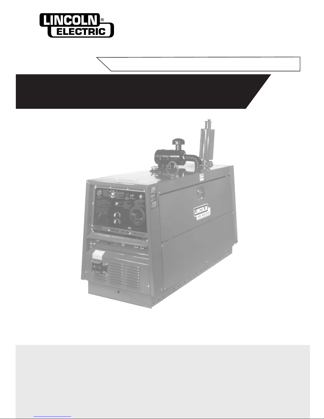
SHIELD-ARC®SAM-400
KA 1355
SAFETY DEPENDS ON YOU
Lincoln welders are designed and built with safety in mind. However, your overall safety can be increased
by proper installation . . . and thoughtful operation on your part. Read and observe the general safety
precautions on page 2 and follow specific installation and operating instructions included in this manual.
Most importantly, think before you act and be careful.
THE LINCOLN ELECTRIC COMPANY
(A
US
TRALIA) PT
Y
.LTD.
A.C.N. 000 040 308
SYDNEY
.
A
USTRALIA
A Subsidiary of
THE LINCOLN ELECTRIC CO. U.S.A.
Associated Subsidiaries in Australia, Europe, Asia, North and South America.
THE
W
ORLD'S LEADER IN
WELDING AND CUTTING PRODUCTS
Page 2 Shield-Arc SAM-400 IMA 523D
PROTECT YOURSELF AND OTHERS FROM POSSIBLE SERIOUS INJUR
Y OR DEATH. READ AND UNDERSTAND
BOTH THE SPECIFIC INFORMATION GIVEN IN THE OPERATING MANUAL FOR THE WELDER AND/OR OTHER
EQUIPMENT TO BE USED AS WELL AS THE FOLLOWING GENERAL INFORMATION.
ARC WELDING SAFETY PRECAUTIONS
1.a. The electrode and work (or ground) circuits are
electrically “hot” when the welder is on. Do not touch
these “hot” parts with your bare skin or wet clothing.
Wear dry, hole-free gloves to insulate hands.
b. In semi-automatic and automatic wire welding, the
electrode, electrode reel, welding head and nozzle or
semi-automatic welding gun are also electrically
“hot”.
c. Insulate yourself from work and ground using dry
insulation. When welding in damp locations, on metal
framework such as floors, gratings or scaffolds, and
when in positions such as sitting or Iying, make
certain the insulation is large enough to cover your
full area of physical contact with work and ground.
d. Always be sure the work cable makes a good
electrical connection with the metal being welded.
The connection should be as close as possible to the
area being welded.
e. Ground the work or metal to be welded to a good
electrical (earth) ground.
f. Maintain the electrode holder, work clamp, welding
cable and welding machine in good, safe operating
condition. Replace damaged insulation.
g. Never dip the electrode holder in water for cooling.
h. Never simultaneously touch electrically “hot” parts of
electrode holders connected to two welders because
voltage between the two can be the total of the open
circuit voltage of both welders.
i. When working above floor level, protect yourself from
a fall should you get a shock.
j. Also see items 4c and 6.
2.a. Welding may produce fumes and gases hazardous to
health. Avoid breathing these fumes and gases.
When welding, keep your head out of the fume. Use
enough ventilation and/or exhaust at the arc to keep
fumes and gases away from the breathing zone.
When welding on galvanized, lead or cadmium
plated steel and other metals which produce toxic
fumes, even greater care must be taken.
b. Do not weld in locations near chlorinated
hydrocarbon vapours coming from degreasing,
cleaning or spraying operations.The heat and rays of
the arc can react with solvent vapours to form
phosgene, a highly toxic gas, and other irritating
products.
c. Shielding gases used for arc welding can displace air
and cause injury or death. Always use enough
v
entilation, especially in confined areas
, to ensure
breathing air is safe.
d.
Read and understand the man
ufacturer’s instructions
f
or this equipment and the consumab
les to be used,
including the material safety data sheet (MSDS) and
follow your employer’s safety practices.
e. Also see Item 7b.
3.a. Use a shield with the proper filter and cover plates to
protect your eyes from sparks and the rays of the arc
when welding or observing open arc welding.
Headshield and filter lens should conform to AS
1674.2-1990 standards.
b
. Use suitable clothing made from durable flame
resistant mater
ial to protect your skin and that of your
helpers from the arc rays.
c. Protect other nearby personnel with suitable non
flammable screening and/or warn them not to watch
the arc or expose themselves to the arc rays or to hot
spatter or metal.
4.a. Remove fire hazards from the welding area. If this is
not possible, cover them to prevent the welding
sparks from starting a fire. Remember that welding
sparks and hot materials from welding can easily go
through small cracks and openings to adjacent
areas. Have a fire extinguisher readily available.
b. Where compressed gases are to be used at the job
site, special precautions should be used to prevent
hazardous situations. Refer to AS1674 Parts 1 & 2
“Safety in Welding and Allied Processes”, WTIA
Technical Note 7 “Health and Safety in Welding” and
the operating information for the equipment being
used.
c. When not welding, make certain no part of the
electrode circuit is touching the work or ground.
Accidental contact can cause overheating and create
a fire hazard.
d. Do not heat, cut or weld tanks, drums or containers
until the proper steps have been taken to insure that
such procedures will not cause flammable or toxic
vapours from substances inside.These can cause an
explosion even though the vessel has been
“cleaned”. For information purchase AS 1674-1990.
e. Vent hollow castings or containers before heating,
cutting or welding. They may explode.
f. Sparks and spatter are thrown from the welding arc.
Wear oil free protective garments such as leather
gloves, heavy shirt, cuffless trousers, high shoes and
a cap over your hair. Wear ear plugs when welding
out of position or in confined places. Always wear
safety glasses with side shields when in a welding
area.
g. Connect the work cable to the work as close to the
welding area as possible. Work cables connected to
the building framework or other locations away from
the welding area increase the possibility of the
welding current passing through lifting chains, crane
cables or other alternate circuits. This can create fire
hazards or overheat lifting chains or cables until they
fail.
h. Also see Item 7c.
ELECTRIC SHOCK can kill
FUMES AND GASES
can be dangerous
ARC RAYS can burn
WELDING SPARKS can
cause fire or explosion
IMA 523D Shield-Arc SAM-400 Page 3
7.a. Turn the engine off before troubleshooting
and maintenance work unless the
maintenance work requires it to be running.
b. Operate engines in open, well-ventilated areas
or vent the engine exhaust fumes outdoors.The
use of this equipment in confined spaces can
result in death
c.
Do not add fuel near an open flame, welding
arc or when the engine is running. Stop the
engine and allow it to cool before refuelling to
prevent spilled fuel from vaporizing on contact
with hot engine parts and igniting. Do not spill
fuel when filling tank. If fuel is spilled, wipe it up
and do not start engine until fumes have been
eliminated.
d. Keep all equipment, safety guards, covers and
devices in position and in good repair. Keep
hands, hair, clothing and tools away from Vbelts, gears, fans and all other moving parts
when starting, operating or repairing
equipment.
e. In some cases it may be necessary to remove
safety guards to perform required maintenance.
Remove guards only when necessary and
replace them when the maintenance requiring
their removal is complete. Always use the
greatest care when working near moving parts.
f. Do not put your hands near the engine fan. Do
not attempt to override the governor or idler by
pushing on the throttle control rods while the
engine is running.
g. To prevent accidentally starting petrol engines
while turning the engine or welding generator
during maintenance work, disconnect the spark
plug wires, distributor cap or magneto wire as
appropriate.
h. To avoid scalding, do not remove the radiator
pressure cap when the engine is hot.
5.a. Use only compressed gas cylinders containing the
correct shielding gas for the process used and properly
operating regulators, designed for the gas and
pressure used. All hoses, fittings, etc. should be
suitable for the application and maintained in good
condition .
b. Always keep cylinders in an upright position and
securely chained to an undercarriage or fixed support.
c. Cylinders should be located:
• Away from areas where they may be struck or
subjected to physical damage.
•
A safe distance from arc welding or cutting
oper
ations and any other source of heat, sparks, or
flame.
d. Never allow the electrode, electrode holder, or any
other electrically “hot” parts to touch a cylinder.
e
. Keep your head and face away from the cylinder valve
outlet when opening the cylinder valve.
f. Valve protection caps should always be in place and
hand-tight except when the cylinder is in use or
connected for use.
g. Read and follow the instructions on compressed gas
cylinders and associated equipment, and AS 2030
Parts 1 & 2.
6.a. Turn off input power using the disconnect switch at the
fuse box before working on the equipment.
b. Install equipment in accordance with the SAA Wiring
Rules, all local codes and the manufacturer’s
recommendations.
c. Ground the equipment in accordance with the SAA
Wiring Rules and the manufacturer’s
recommendations.
CYLINDER may explode if
damaged
FOR ENGINE
powered equipment
FOR ELECTRICALLY
powered equipment
HAVE ALL INSTALLATIONS, OPERATION, MAINTENANCE AND REPAIR WORK PERFORMED BY QUALIFIED PEOPLE
For more detailed information it is strongly recommended that you purchase a copy of “Safety in Welding and Cutting - ANSI
Standard Z 49.1 “ and WTIA Technical Note 7. All WTIA publications and ANSI/AWS Standards are available from the Welding
Technology Institute of Australia, P.O. Box 6165, Silverwater NSW 2128. For copies of various Australian Standards contact your
local S.A.A. office.
HOW TO ORDER REPLACEMENT PARTS
To ensure that you receive the correct replacement part the following procedure should be followed:
1. Quote Serial Number and Code Number as listed on the welder.
2. Quote the Description, Item Number and Parts List Number of the desired part. When ordering parts for items carrying brand
names of other companies, such as fan motors, drive shafts, etc., be sure to include the other company’s name and part
number and other relevant information.
3. Parts should be ordered from The Lincoln Electric Company, its offices or the nearest Authorised Field Service Shop. (The
“Lincoln Ser
vice Director
y”
listing these shops geographically is available on request.)
* “Hardware” in the Lincoln Parts Lists are not Lincoln stock items but can be obtained via the Field Service Shop network.
Component parts of assemblies such as stator coils or armature coils, etc., which require electrical testing or locating fixtures are
not considered replaceable items.This is to ensure that the customer receives parts which will keep the welder in the best operating
condition.
BUY ONLY GENUINE REPAIR PARTS

Page 4 Shield-Arc SAM-400 IMA 523D
All welders should follow safe practices that minimise their
exposure to electric and magnetic fields (EMF).
For welders wearing implanted pacemakers, safe welding
practices are particularly important and additional procedures
should be followed by those who have decided to continue to
weld. (Hopefully in keeping with a Doctor’s advice).
The following procedures will not eliminate exposure to EMF or
the possibility of arc welding having an affect on a pacemaker,
however, if followed, they will significantly reduce exposure to
electric and magnetic fields. Electric and magnetic fields are
created any time electric current flows through a conductor,
however it is not clear whether such exposure affects ones
health.
Some researchers have reported that exposure to EMF may
cause leuk
emia or other illnesses. These claims originally
arose in relation to high voltage electric power lines and are
v
ery much in dispute in the medical and scientific arena,
however the best advice is to minimise your exposure to EMF
to protect your health should doctors eventually decide there is
a risk.
There are four fundamental facts about EMF:
• With direct current (DC), the field strength is relatively
constant and does not change.
• With alternating current (AC), the field strength constantly
changes.
• The greater the current flow, i.e. the higher the amps,
the stronger the field created by the current.
• The closer the conductor or electrical device is to the
body, the greater the exposure to the field.
Minimising Exposure
All welders should use the following procedures to minimise
EMF exposure.
• Route electrode (or gun) and work cables together.
Secure them with tape if possible.
• Never coil the electrode lead around your body
• Do not place your body between the electrode and
work cables. If your electrode cable is on the right side,
the work cable should also be on your right side.
• Connect the work cable to the work piece as close as
possible to the area being welded. (This is also a good
practice to eliminate a common problem in welding - a
poor work connection).
Welders with Pacemakers
There is no question that the fields in arc welding can interfere
with a pacemakers function. Generally the interference does
not permanently damage the pacemaker. Once the wearer
leaves the arc welding environment or stops welding, the
pacemaker returns to normal functioning. The welding arc has
little or no effect on the operation of some pacemakers,
especially designs that are by-polar or designed to filter out
such interference.
For a welder or anyone working around electrical equipment,
the selection of a pacemak
er is very important. Get a Doctor’s
advice about which pacemak
er is the least sensitive to
interference from welding while still being medically suitable.
In addition to the normal saf
ety precautions, the following
additional procedures should be adopted b
y welders with
pacemak
ers.
• Use gas welding when the application is suitable.
• Use the lowest current setting appropriate for the
application. Do not exceed 400 amps. Low current (75200 amps) direct current (DC) welding should be used
is arc welding is necessary. Do not Tig weld with high
frequency.
• Do not use repeated, short welds. Wait about ten
seconds between stopping one weld and starting the
next. When having difficulty starting an electrode, do
not re-strike the rod repeatedly.
• If you feel light headed, dizzy or faint, immediately stop
welding. Lay the electrode holder down so that it does
not contact the work and move away from any welding
being performed. Arrange your work in advance so
that, if you become dizzy and drop the electrode holder,
the electrode will not fall on your body or strike the work.
• Do not work on a ladder or other elevated position or in
a cramped confined place.
• Do not work alone. Work only in the presence of an
individual who understands these precautions and the
possible effect welding may have on your pacemaker.
• Do not work near spot welding equipment.
• If you have a pacemaker and wish to continue arc
welding, discuss this and any other questions you may
have with your physician and follow his or her advice.
The doctor may wish to contact the pacemaker
manufacturer for a recommendation. As mentioned
before the design of the pacemaker significantly affects
the degree to which it is subject to interference from a
welding circuit. Do not rely on the fact that you
know another welder with a pacemaker who haswelded for
years without experiencing a problem.That welder and his
or her pacemaker may be quite different from you and your
pacemaker.
WELDING EMF AND PACEMAKERS

IMA 523D Shield-Arc SAM-400 Page 5
The purchaser is responsib
le for installing and using the
welding equipment according to the manufacturer’s
instructions. If electromagnetic disturbances are detected
then it shall be the responsibility of the user of the welding
equipment to resolve the situation with the technical
assistance of the manufacturer. In some cases this
remedial action may be as simple as earthing the welding
circuit. In other cases it could involve constructing an
electromagnetic screen enclosing the power source and
the work complete with associated input filters. In all cases
electromagnetic disturbances must be reduced to the point
where they are no longer troublesome.
NOTE: The welding circuit may or may not be earthed for
safety reasons. Changing the earthing arrangements
should only be authorised by a person who is competent to
assess whether the changes increase the risk of injury, e.g.
by allowing parallel welding current return paths which may
damage the earth circuits of other equipment.
Assessment of Area
Before installing welding equipment the user shall make an
assessment of potential electromagnetic problems in the
surrounding area.
The following shall be taken into account:
a. Other supply cables, control cables, signalling and
telephone cables; above, below and adjacent to the
welding equipment;
b. Radio and television transmitters and receivers;
c. Computer and other control equipment;
d. Critical safety equipment, e.g. automatic machine
guards;
e. Personal electronic equipment, e.g. pacemakers and
hearing aids;
f. Equipment used for calibration or measurement;
g. The immunity of other equipment in the environment.
The user shall ensure that other equipment being used
in the environment is compatible. This may require
additional protection measures;
h. The time of the day that welding or other activities are to
be carried out.
The size of the surrounding area to be considered will
depend on the structure of the building and other activities
that are taking place
.
The surrounding area may extend
beyond the boundaries of the premises.
Methods of Reducing Emissions
Maintenance of the Welding Equipment
The welding equipment should be routinely maintained
according to the manufacturer’s recommendations. All
access and service doors and covers should be closed and
properly fastened when the welding equipment is in
oper
ation. The welding equipment should not be modified in
an
y way except for those changes and adjustments covered
in the manufacturers instructions. In particular, the spark
gaps of arc initiation and stabilising devices should be
adjusted and maintained according to the manufacturers
recommendations.
Welding Cables
The welding cables should be kept as short as possible and
should be positioned close together, running at or close to
the floor level.
Earth Bonding of Installation
Bonding of all metallic components in the welding
installation and adjacent to it should be considered.
However, metallic components bonded to the work piece
will increase the risk that the operator could receive a shock
by touching these metallic components and the electrode at
the same time. The operator should be insulated from all
such bonded metallic components.
Earthing of the Workpiece
Where the workpiece is not bonded to earth for electrical
safety, nor connected to earth because of its size and
position, e.g. ships hull or building steelwork, a connection
bonding the workpiece to earth should be made by a direct
connection to the workpiece. In some countries where direct
connection is not permitted, the bonding should be
achieved by suitable capacitance, selected according to
national regulations.
Screening and Shielding
Selective screening and shielding of other cables and
equipment in the surrounding area may alleviate problems
of interference. Screening of the entire welding installation
may be considered for special applications.
INSTRUCTIONS FOR ELECTROMAGNETIC COMPATIBILITY
This welding machine must be used by trained operators only.
Read this manual carefully before attempting to use the
welding machine.
WARNING
Page 6 Shield-Arc SAM-400 IMA 523D
BEFORE STARTING THE ENGINE
On receipt of machine, remove “Gold Seal” or “Carecard”
label from engine, add ownership details, and mail to
nearest Perkins Distributor. The Distributor will return a
plastic Carecard which must be retained and presented
should warranty service be required. Note that the
Carecard is accepted world-wide.
Before attempting to start the engine, the following
should be carried out:
1.
Ensure the crankcase oil level is at the “Full” mark
on the dipstick. Use only the grade oil recommended
by the engine manufacturer in accompanying Engine
Manual.
N.B.: Many oil companies market a product which
meets the recommended MIL-L-46152 (SE CC) and
the heavy duty and turbocharged engine
specification MIL-L-2104C (SE CD). These oils are
not recommended for use in this w
elder, particularly
in the initial 50 hours of operation.
2. Fill the r
adiator
.
Be sure to add Alfloc 2000 to
radiator as per container instructions. This is
required for corrosion resistance.
3. Fill the fuel tank (alw
a
ys use clean fuel).
4. In the case of a new engine or an engine which has
been standing idle f
or an
y length of time
, it is
important to bleed the fuel system. Always use the
manual primer on the lift pump to circulate fuel in the
system. Extensive use of the electric starter for this
purpose may lead to electrical component damage.
Refer to the engine instruction manual for the correct
procedure.
5. Fill the dry charged battery. See page 8.
TO START THE WELDER
Turn the start switch to the “H” position for 15-20
seconds, then turn further in the clockwise direction to
the “Hs” position. If the engine does not start after 20
seconds, return the switch to the “H” position for 10
seconds and then return to the “Hs” position again for a
maximum period of 30 seconds. If the engine still does
not start, allow at least 10 minutes for the starter motor
and other electrical components to cool before repeating
the starting procedure. As soon as the engine starts, the
start switch should be released and allowed to return to
the
“R” position. If the engine is warm and has only been
stopped for a short period, restart by turning the start
s
witch directly on to the
“Hs”
position and releasing when
the engine starts.
ENGINE
Model Perkins 4/236 Diesel
Capacity 3.9 litres (236 cu. ins.)
Lubrication High pressure forced feed
from rotary type oil pump
Cooling Water cooling with circulation
by centrifugal pump
Governor Mechanical, on fuel injection
pump
Fuel Tank Capacity 63.7 litres (14 gallons),
sufficient for well over one
day’s operation under severe
conditions
Starting 12 volt starter, alternator and 11
plate battery
WELDER
Specification No. KA-1355
Model Shield-Arc®SAM400
Rated Output 400 amps @ 40 arc volts and
60% duty cycle (exceeds
AS1966 requirements)
Welding Current Constant Voltage: 60-600 amps
Range Constant Current : 80-600 amps
Speeds: No Load 1800 r.p.m.
Full Load 1700 r.p.m.
Weight 900kg. (approx.)
(dry - without trailer)
Auxiliary Power 240/115 volt A.C., 60Hz
OPERATING INSTRUCTIONS
IMPORTANT NOTE ABOUT “RUNNING IN” YOUR DIESEL ENGINE
All diesel engines require some additional care for about the first 50 hours operation. While maximum load can be
applied to a new engine as soon as it is put into service and the coolant temperature has reached
at least 60°C, care
should be taken that the engine is not run at very light loads (say less than 2.4 kVA, or a 10 amp radiator) for extended
periods, as this can lead to glazing of the cylinder bores. Do not operate at high speeds without a load, and do not
overload the engine. Cylinder glazing can lead to excessive oil consumption and smoky exhaust, while overloading
FOR ENGINE
powered equipment
SPECIFICATIONS
ENGINE OPERATION AND MAINTENANCE
See the engine manufacturer’s operating manual supplied with the welder for detailed engine operating and
maintenance instructions, parts lists and safety precautions.
Operate internal combustion engine in open, well
ventilated areas or vent the exhaust fumes
outdoors.
Whenever starting the engine, be sure any welding
loads are removed and any A.C. auxiliary loads
either turned off or the plugs pulled. If the load is
left connected it may prevent the generator from
building up to full voltage.
CAUTION

IMA 523D Shield-Arc SAM-400 Page 7
OUTPUT CHARACTERISTICS
This machine generates both constant voltage and
variable voltage output. Variable voltage is always used
for stick electrode welding and sometimes for
submerged arc welding. Constant voltage is always used
for Innershield
®
and other open arc welding processes,
and is usually preferred for submerged arc welding with
small wires.
PORTABLE FIELD CONTROL CONNECTION
A ‘Portable Field Control’ complete with 7.6m leads is
shipped with each SAM welder.
A ‘Portable Field Control’ is
not required for proper
operation of the SAM welder when connected to an LN23P, LN-8 or LN-9 semi-automatic or NA-3, LT-7 or NA-5
fully automatic wire feeder. With other wire feeders and
when stick electrode welding, the ‘Portable Field Control’
must be installed or the SAM cannot produce its full
open circuit voltage.
When installed the ‘Portable Field Control’ is a fine
voltage adjustment when using the SAM as a constant
voltage power source. It is a fine current adjustment when
using the SAM as a variable voltage power source.
The ‘Portable Field Control’ can be mounted on the SAM
or wherever convenient for the welding operation. When
using an LN-7, LN-25, LN-21 or LN-22 wire feeder, the
control should normally be mounted on the wire feeder.
Connect the ‘Portable Field Control’ leads to #75 and
#76 on the SAM terminal strip. Connect the green lead of
the ‘Portable Field Control’ to the grounding stud marked
with the symbol located next to the terminal strip.
OUTPUT CONNECTIONS
If the oil pressure gauge does not show normal oil
pressure (207/414kPa) 10 seconds after starting,
stop the engine and consult the engine instruction
manual.
CONTROL SETTINGS
(Also see visual presentation of control setting instructions on pages 12 and 13)
WELDER CONNECTION AND OPERATION
(a) for Stick Electrode Welding
1. Connect the electrode cable to the ‘Stick’ stud and
the work cable to the ‘To Work’ stud.
2. Install the ‘Portable Field Control’.
(b) LN-7, LN-8, LN-9, LN-21, LN-22, LN-25, LN-23P, NA-
3, NA-5 and LT-7 Wire Feeders
1. Make the connections exactly as specified on the
connection wiring diagram on pages 8 & 9, or as
included in the Wire Feeder Instruction Manual.
2. Install the ‘Portable Field Control’ (LN-7, -21, -22
and -25 only).
3. Be sure the wire feeder is properly set for constant
or variable voltage as appropriate.
(c) Other Wire Feeders
This power source can be used with other Lincoln
wire feeders and wire feeders manufactured by other
companies. The connection must be determined by
the customer for the specific equipment being used.
115V AC & 42VAC auxiliary power are available for
wire feeder operation from 31 and 32 and 32 & 41
respectively on the SAM terminal strip. To operate the
SAM contactor, connect the appropriate wire feeder
control circuit to close the circuit from #2 to #4 on the
terminal strip.
AUXILIARY POWER
Both 240V. and 115V., 60Hz. AC are available from
outlets below the nameplate. Be careful not to overload
these circuits. Maximum total current draw is 15 amps
from both outlets - i.e. if drawing 10 amps of 240V. power,
only 5 amps of 115V. power may be used.
The alternator is protected by thermostats and fuses.
See “Trouble Shooting” for information on the effects of
these protective devices.
Important: The Shield-Arc SAM-400 auxiliary power
circuits are not connected to the welder frame, and
earth leakage protection is not required (refer
AS2790-1989, Clause 6.1.9(a) and Comment 1),
ho
we
ver connected equipment should be doub
le
insulated, or fitted with an effective earth wire. Do
not use equipment connected to the auxiliary power
outlets while the machine is also supplying welding
current.
TO STOP THE ENGINE
Turn the key switch to “O” position. The engine speed
has been pre-set in the factory for optimum welder
performance and the fuel pump and governor then
sealed. This setting should not be altered, to do so will
void the warranty. For normal running, lubricating and
maintenance instructions, consult the engine instruction
manual. For correct cooling air flow, the welder should be
operated with the doors closed.
Notwithstanding the above, should a residual
current device (RCD) be fitted to the machine, it is
imperative that the frame of the machine be
earthed in accordance with AS3000, Clause 5.6. An
effective earth is essential for the safe operation of
mac
hines fitted with RCD de
vices.
WARNING
Failure to return the key switch to “R” position, or
turning to “Hs” position while engine is running will
cause electrical component dama
ge.
WARNING

Page 8 Shield-Arc SAM-400 IMA 523D
USE OF WELDERS AS STAND-BY POWER UNITS
W
elders with 240 volt 60Hz auxiliary AC outlets can be
used as stand-by power units. To avoid the possibility of
electric shock and/or damage to the welding machine,
connections and alterations must be made by a licensed
electr
ician, who can determine how the machine can be
adapted to the particular installation and comply with the
local Supply Authority regulations.
It is also impor
tant that an adequately rated isolation
switch is used to ensure that the stand-by power unit and
the A
uthorities’ Supply are not connected in parallel.
OUTPUT STUDS
Connect the w
ork cable to the “Work” stud. For stick
electrode welding, connect the electrode cable to the
“Stick” stud. For all mechanised welding processes,
connect the welding power cable from the wire feeder to
the “Connect to Auto. Equipment” stud.
TOGGLE SWITCH
This switch is located on the front of the control panel on
the nameplate. Set the switch to ‘Variable Voltage’ or
‘Constant Voltage’ as appropriate for the welding process
to be used (see sketches on pages 12 and 13).
CONTACTOR
The output contactor is automatically in the welding
circuit when the machine is properly connected to a
Lincoln
®
wire feeder through the ‘Connect to Auto.
Equipment’ stud. It closes when the gun trigger is
pressed and opens when the trigger is released. The
contactor is not in the welding circuit when using the
‘Stick’ stud.
ELECTRODE POLARITY SWITCH
Select straight [DC(-)] or reverse [DC(+)] electrode
polarity as needed. This switch must also be set for
either constant or variable voltage welding as
appropriate (see sketches on pages 12 and 13).
DO NOT SWITCH WHILE WELDING
CONSTANT VOLTAGE RANGE SELECTOR
This switch is on the lower front panel. Set to “11 to 18
arc volts” position when using CV procedures requiring
arc voltages in this range.
DO NOT SWITCH WHILE WELDING.
CURRENT AND VOLTAGE CONTROLS
Constant Voltage Welding
The ‘Current Control’ is NOT in the circuit when the
‘Electrode Polarity’ switch is set for constant voltage
welding.
Set the open-circuit voltage (OCV) needed for the
particular application with the ‘Constant Voltage Control’
located on the nameplate and set the ‘Constant Voltage
Range Selector’. Adjust the final welding voltage with
either the wire feeder voltage control (see connection
instructions) or the ‘Portable Field Control’. Set the
welding current with 'Amps’ or ‘Wire Feed Speed’ control
on the wire feeder.
A Hot Start circuit operates automatically whenever the
toggle switch is set on ‘Constant Voltage’. It increases
the open circuit voltage by several volts until the arc is
established - then the voltage automatically drops to
normal welding voltage. When the gun trigger is pressed
before the arc is started, the voltmeter indicates a
voltage several volts higher than welding voltage.To read
actual welding voltage, the arc must be established.
Constant
Voltage Welding with Variable Inductance
Control
Variable inductance or slope control is usually required
for dip transfer GMA applications and is sometimes
useful in other constant v
oltage jobs.
To introduce this control into the circuit, set the
‘Electrode Polarity’ switch to ‘Variable Voltage’ and the
toggle s
witch to ‘Constant Voltage’. Then the ‘Current
Control’ acts as the variable inductance control. Normally
this control m
ust be kept within the 8 to 1 o’clock range.
Set the welding current and voltage as described under
‘Constant Voltage Welding’ above.
Variable Voltage Welding
Ensure ‘Constant Voltage Range Selector’ switch is in
‘16-max’ position. The ‘Current Control’ provides the
major adjustment of current. It has two calibrated scales;
one gives maximum and the other minimum current
available at any given setting. DO NOT ADJUST THE
‘CURRENT CONTROL’ WHEN WELDING.
The ‘Variable Voltage Control’ on the nameplate is both
the open circuit voltage control and a fine current
adjustment
The wire feeder current control and the ‘Portable Field
Control’ provide the same function as the ‘Variable
Voltage Control’ (see connection instructions).
To Set Controls - Stick Welding
a. Make the coarse setting of welding heat with the
‘Current Control’.
b. Adjust for the desired arc characteristics with the
‘Variable Voltage Control’. For a soft arc, as desired
for most welding, keep this control between 7 and
High. For a more digging arc, set it lower.
c. If remote control is NOT desired leave the ‘Portable
Field Control’ on ‘High’. For remote control, leave the
‘Variable Voltage Control’ near ‘High’ and make the
adjustments described in paragraph ‘b’ above with
the ‘Portable Field Control’. Remember, increasing
either the ‘Variable Voltage Control’ or ‘Portable Field
Control’ setting also increases the current.
To Set the Controls - Submerged Arc
a. The open circuit voltage (OCV) is generally not
critical in submerged arc welding. Therefore, the
‘Variable Voltage Control’ can usually be left between
7 and ‘High’ - no further adjustments are needed.
b. Set ‘Current Control’ so the calibration on the higher
scale is a little above the current desired.
c. Make the final current adjustments with either the
wire feeder current control or the ‘Portable Field
Control’. Set the arc voltage with the wire feeder
control.

IMA 523D Shield-Arc SAM-400 Page 9
TO GAIN ACCESS TO BATTERIES:
Remove the lower rear panel (radiator end).
NOTE: Batteries must not be filled or “Topped Up” whilst
they are in normal operating position. (Remove them
from the machine first).
COMMISSIONING AND RECHARGING
INSTRUCTIONS
1 - Remove the battery from the machine before filling or
recharging.
2 - Remove and retain vent plugs.
3 - Fill each cell of the battery to the top of the separators with
the correct grade electrolyte* (ie. 1.260 specific gravity).
Using higher or lower specific gravity electrolyte than
recommended can impair the battery performance.
4 - Boost charge the battery at 15amps until the specific
gravity of the electrolyte is 1.250 or higher and the
electrolyte temperature is at least 15˚C
BOTH
CONDITIONS MUST BE MET.
If electrolyte bubbles violently while charging, reduce the
charging rate until the excessive bubbling action subsides,
then continue until both of the above conditions are
achieved.
If the ambient temperature is 10˚C or less, it is imperative
that the above instructions be followed.
5 - After boost charge check level of electrolyte in all cells. Add
additional electrolyte to bring level to that shown on
labelling.
DO NOT OVERFILL. After the battery has been in
service, add only approved water.
DO NOT ADD ACID.
NB.
Depending on the age of the dry charged battery
correct activation may take up to 48 hours.
6 - Disconnect the battery from the charging source and refit
the vent plugs ensuring they are screwed or pushed all the
way home.
7 - Wash away any spilt electrolyte with water and dry the
battery completely before installing it into the machine.
INSTALLATION
1 - Inspect the battery tray and remove any foreign objects that
may be present.
2 - Place the battery in the tray.
3 - Connect the positive battery lead (marked with a red band),
then connect the negative lead.
NB. Always connect the negative lead last when installing a
battery.
4 - Refit the battery hold-down assembly. Do not overtighten
this assembly as battery case damage is possible.
BATTERY MAINTENANCE
1 - Keep the electrolyte levels about 6mm above the plates and
separators.
2 - Keep terminal posts free of corrosion.
3 - Keep battery clean and dry.
4 - Do not leave machine switched on without the engine
running as this will discharge the battery.
5 - Do not fast charge any battery over 18 months old.
6 - Never add acid to a battery unless it has been lost through
spillage.
*NO
TE:To prevent acid surge from bottle when filling,
pierce a small hole in the top of the acid bottle to allo
w
bottle to “breathe”.
IMPORTANT SAFETY INSTRUCTIONS
• Battery electrolyte contains SULPHURIC ACID which
is corrosive to skin and clothing.
• Batteries also contain EXPLOSIVE GASES.
• Do not do anything to cause sparks near the battery.
Keep naked flames and cigarettes away from batteries.
•
If acid contacts eyes or skin FLUSH IMMEDIATELY with
large quantities of CLEAN DRINKING WATER.
• IN CASE OF ACID CONTACTING THE EYES,
IMMEDIATELY FLUSH WITH WATER FOR 20 MINUTES
AND CONSULT A DOCTOR.
•
After use wash out empty electrolyte bottles with water
and dispose of carefully - do not use empty electrolyte
bottles for any other purpose.
• ALWAYS KEEP BATTERIES AND ELECTROLYTE OUT
OF REACH OF CHILDREN.
• DISPOSE OF OLD BATTERIES CAREFULLY.
• WHEN CHARGING, PROVIDE ADEQUATE
VENTILATION TO ALLOW THE SAFE ESCAPE OF
EXPLOSIVE GASES
.
Whenever possible have a qualified electrician do the
needed electrical maintenance and trouble shooting
work. Turn the engine off when working inside the
machine.
ROUTINE MAINTENANCE
1. AFTER 25 HOURS OF USE OF YOUR NEW
WELDER, CHECK ALL NUTS AND BOLTS FOR
TIGHTNESS. Thereafter check all nuts and bolts
every 1000 hours of operation.
2. Blow out the welder and controls with an air hose at
least once every two months. In particularly dirty
locations this cleaning may be necessary once
every week. Use low pressure air to avoid driving dirt
into the insulation.
3. Current Control reactor brushes are silver graphite
and should not be greased. Keep the contacts clean.
4. Keep electrode and work connections tight.
BEARINGS
Your welder is equipped with a double-shielded ball
bearing having sufficient grease to last indefinitely under
normal conditions. Where the welder is used constantly
or in excessively dirty locations, it may be necessary to
add 15 grams of grease per year.
When greasing the bearing, keep all dirt out of the area.
Wipe the fitting completely clean and use clean grease
and equipment. More failures are caused by dirt
introduced while greasing than from insufficient grease.
COMMUTATOR AND BRUSHES
The gener
ator and alter
nator br
ushes are properly
adjusted when the w
elder is shipped. They require no
particular attention. DO NOT SHIFT THE BRUSHES or
adjust the roc
k
er setting.
Periodically inspect the commutator and brushes.
WELDER MAINTENANCE
BATTERY FILLING AND SERVICE INSTRUCTIONS

Page 10 Shield-Arc SAM-400 IMA 523D
WARNING: This procedure is only suitable for
applications using DC Mega Testers up to 500V.
Note: This procedure is for ‘machines as built’ many
modifications could have taken place over the life of a
particular machine, so details of this procedure may
need to be ‘adjusted’to suit these mfield service shop.The
insulation resistance values listed below are from
Australian Standard AS1966.2.
1. Ensure engine is stopped.
2. Remove welding leads and disconnect any auxiliary
equipment cables.
3. Disconnect the leads from the battery charge
alternator (mounted on the engine).
4. Disconnect the negative and positive battery leads.
5. Jumper together the positive, negative and three AC
terminals of the bridge rectifiers (mounted on the
stator).
6. Place the key switch in the ‘run’ position and the
auxiliary switch to the ‘on’ position.
7. Remove thermostart lead from terminal No.5 on the
key switch.
8. Remove the earth leads from:
- the water temperature guage and sender.
- the stop solenoid (mounted in the engine fuel
injector pump),
- the hour meter & engine watcher warning light (if
fitted)
9. Remove all harness plugs and other connections to
the PCB and isolate them from the case.
contact is made across the full face of the brushes.
After stoning blow out the dust with low pressure air.
CA
UTION: Uncovered rotating equipment can be
dangerous. Use care so your hands, clothing or tools do
not catch in the rotating parts. Protect yourself from
particles that may be thrown out by the rotating armature
when stoning the comm
utator.
CONTACTOR MAINTENANCE
Where the output contactor is operated frequently when
tacking or making short welds, turn the engine off and
inspect the contactor every three months.
1.
Be sure the mating surfaces of silver contacts are
not worn and all make contact at approximately the
same time.
2. Make sure the springs and holders are not broken or
out of adjustment. Approximate spring compression
after making contact is 3mm. Less than 1
1
⁄2mm
compression indicates worn contacts that should be
replaced.
3. Make sure the moving contact and other moving
parts are not binding.
4. Be sure mounting screws are tight.
Commutators and slip rings require little attention.
However, if they are black or appear uneven, have an
experienced maintenance man clean them with fine
sandpaper or a comm
utator stone. Never use emery
cloth or paper for this purpose.
Ha
ve an experienced maintenance man replace brushes
when they wear within 6mm of the pig tail. A complete
set of replacement brushes should be kept on hand.
Before fitting replacement brushes, twist the brush pig
tail at its entrance to the brush until the strands are
tightly packed and no part of the pig tail protrudes
be
yond the brush surface in the pig tail slot. When the
brush is placed in the holder, clear the pig tail from the
side of the holder to allow free radial movement of the
brush.
Sand new slip ring brushes by placing a piece of
sandpaper between the brushes and the slip ring with
the abrasive side against the brushes. With light finger
pressure on the brushes, pull the sandpaper around the
circumference of the rings only until the brushes are
properly seated. Stone the slip rings with a 320 grit
sanding stone. Slip rings must be clean and free from oil
and grease.
Lincoln commutator brushes have a curved face to fit the
commutator. Seat these brushes by lightly stoning the
commutator as the armature rotates at full speed until
10.Auxiliary circuit test: Connect one lead of the mega
tester to the frame of the machine and the other lead
to lead #31. Apply the test. (Min. resistance 1MΩ)
11.Welding circuit test (a): Connect one lead of the mega
tester to the frame of the machine and the other lead
to the generator brushes. Apply the test. (Min.
resistance 1MΩ)
12.Welding circuit test (b): Connect one lead of the mega
tester to the frame of the machine and the other lead
to the automatic output stud. Apply the test. (Min.
resistance 1MΩ)
13.Field circuit test: Connect one lead of the mega tester
to the frame of the machine and the other lead to one
of the slip ring brush pig tails. Apply the test. (Min.
resistance 1MΩ)
14.Auxiliary to weld circuit test: Connect one lead of the
mega tester to lead #31 and the other to the
generator brushes. Apply the test. (Min. resistance
10MΩ)
15.Auxiliary to field circuit test: Connect one lead of the
mega tester to lead #31 and the other to one of the
slip ring brush pig tails. Apply the test. (Min.
resistance 1MΩ)
16.Weld to field circuit test: Connect one lead of the
mega tester to the generator brushes and the other
lead to one of the slip ring brush pig tails. Apply the
test.
(Min.
resistance 1M
Ω
)
17.
Remo
v
e all jumper leads
. Reconnect all leads
disconnected during this procedure.
If an
y prob
lems are encountered ref
er to y
our nearest
author
ised Lincoln Field Ser
vice Shop
.
GROUND TEST PROCEDURE
 Loading...