

Lincoln Electric SHIELD-ARC 400AS-50 Operating Manual
IMA 554C
September 1998
OPERATING MANUAL
THE LINCOLN ELECTRIC COMPANY
(AUSTRALIA) PTY. LTD.
A.B.N.
36 000 040 308
SYDNEY. AUSTRALIA
A Subsidiary of
THE LINCOLN ELECTRIC CO. U.S.A.
Associated Subsidiaries in A
ustralasia,
Asia, Canada, Europe, North and South America.
THE WORLD’S LEADER IN WELDING AND CUTTING PRODUCTS
SAFETY DEPENDS ON YOU
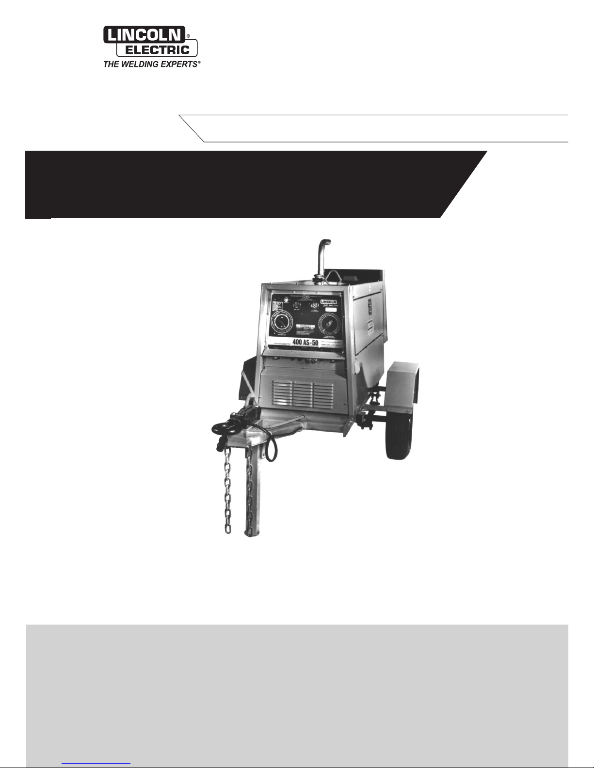
Lincoln Electric welders are designed and built with safety in mind. However, your overall safety can be
increased by proper installation and thoughtful operation on your part. Read and observe the general safety
precautions on page 2 and follow specific installation and operating instructions included in this manual.
Most importantly, think before you act and be careful.
SHIELD-ARC
®
400AS-50
WITH 12 VOLT ELECTRICS - KA1352
PROTECT YOURSELF AND OTHERS FROM POSSIBLE SERIOUS INJURY OR DEATH. READ AND UNDERSTAND
B
OTH THE SPECIFIC INFORMATION GIVEN IN THE OPERATING MANUAL FOR THE WELDER AND/OR OTHER
EQUIPMENT T
O BE USED AS WELL AS THE FOLLOWING GENERAL INFORMATION.
ARC WELDING SAFETY PRECAUTIONS
1. a. The electrode and work (or ground) circuits are
electrically “hot” when the welder is on. Do not touch
these “hot” parts with your bare skin or wet clothing.
Wear dry, hole-free gloves to insulate hands.
b. In semi-automatic and automatic wire welding, the
electrode, electrode reel, welding head and nozzle or
semi-automatic welding gun are also electrically “hot”.
c. Insulate yourself from work and ground using dry
insulation. When welding in damp locations, on metal
framework such as floors, gratings or scaffolds, and
when in positions such as sitting or lying, make certain
the insulation is large enough to cover your full area of
physical contact with work and ground.
d. Always be sure the work cable makes a good electrical
connection with the metal being welded. The
connection should be as close as possible to the area
being welded.
e. Ground the work or metal to be welded to a good
electr
ical (earth) ground.
f. Maintain the electrode holder, work clamp, welding
cable and welding machine in good, safe operating
condition. Replace damaged insulation.
g. Never dip the electrode holder in water for cooling.
h. Never simultaneously touch electrically “hot” parts of
electrode holders connected to two welders because
voltage between the two can be the total of the open
circuit voltage of both welders.
i. When working above floor level, protect yourself from
a fall should you get a shock.
j. Also see items 4c and 6.
2. a. Welding may produce fumes and gases hazardous to
health.
A
v
oid breathing these fumes and gases
.
When
welding, keep your head out of the fume. Use enough
ventilation and/or exhaust at the arc to keep fumes and
gases away from the breathing zone. When welding on
galv
anised, lead or cadmium plated steel and other
metals which produce toxic fumes, even greater care
must be taken.
b. Do not weld in locations near chlorinated hydrocarbon
vapours coming from degreasing, cleaning or spraying
operations. The heat and rays of the arc can react with
solv
ent v
apours to form phosgene, a highly toxic gas,
and other irritating products.
c.
Shielding gases used for arc welding can displace air
and cause injury or death. Always use enough
ventilation, especially in confined areas, to ensure
breathing air is safe.
d. Read and understand the manufacturer’ s instructions
f
or this equipment and the consumab
les to be used,
including the material safety data sheet (MSDS) and
follow your employer’s safety practices.
e. Also see Item 7b.
3. a. Use a shield with the proper filter and cover plates to
protect your eyes from sparks and the rays of the arc
when welding or observing open arc welding.
Headshield and filter lens should conform to AS
1674.2-2003 AS1337-1992 and AS1338-1992
standards.
b. Use suitable clothing made from durable flame
resistant material to protect your skin and that of your
helpers from the arc rays.
c. Protect other nearby personnel with suitable non
flammable screening and/or warn them not to watch
the arc or expose themselves to the arc rays or to hot
spatter or metal.
4. a. Remove fire hazards from the welding area. If this is
not possible, cover them to prevent the welding sparks
from starting a fire. Remember that welding sparks and
hot materials from welding can easily go through small
cracks and openings to adjacent areas. Have a fire
extinguisher readily available.
b. Where compressed gases are to be used at the job
site, special precautions should be used to prevent
hazardous situations. Refer to AS1674 Parts 1 & 2
“Safety in Welding and Allied Processes”, WTIA
Technical Note 7 “Health and Safety in Welding” and
the operating information for the equipment being
used.
c. When not welding, make certain no part of the
electrode circuit is touching the work or ground.
Accidental contact can cause overheating and create a
fire hazard.
d.
Do not heat, cut or w
eld tanks
, dr
ums or containers
until the proper steps have been taken to insure that
such procedures will not cause flammable or toxic
v
apours from substances inside
. These can cause an
e
xplosion e
v
en though the v
essel has been “cleaned”.
For information purchase AS 1674-1990.
e. Vent hollow castings or containers before heating,
cutting or welding. They may explode.
f
. Sparks and spatter are thrown from the welding arc.
W
ear oil free protectiv
e garments such as leather
glo
v
es
, hea
vy shir
t, cuffless trousers
, high shoes and
a cap over your hair. Wear ear plugs when welding out
of position or in confined places. Always wear safety
glasses with side shields when in a w
elding area.
g.
Connect the w
or
k cable to the work as close to the
welding area as possible. Work cables connected to
the building framework or other locations away from
the w
elding area increase the possibility of the welding
current passing through lifting chains
, cr
ane cab
les or
other alternate circuits. This can create fire hazards or
overheat lifting chains or cables until they fail.
h. Also see Item 7c.
ELECTRIC SHOCK can kill
FUMES AND GASES
can be dangerous
ARC RAYS can burn
WELDING SPARKS can
cause fire or explosion
5. a. Use only compressed gas cylinders containing the
correct shielding gas for the process used and
properly operating regulators, designed for the gas
and pressure used. All hoses, fittings, etc. should be
suitable for the application and maintained in good
condition.
b. Always keep cylinders in an upright position and
securely chained to an undercarriage or fixed support.
c. Cylinders should be located :
• Away from areas where they may be struck or
subjected to physical damage.
• A safe distance from arc welding or cutting
operations and any other source of heat, sparks or
flame.
d. Never allow the electrode, electrode holder, or any
other electrically “hot” parts to touch a cylinder.
e. Keep your head and face away from the cylinder valve
outlet when opening the cylinder valve.
f. Valve protection caps should always be in place and
hand-tight except when the cylinder is in use or
connected for use.
g. Read and follow the instructions on compressed gas
cylinders and associated equipment, and AS 2030
Parts 1 & 2.
6. a. Turn off input power using the disconnect switch at the
fuse box before working on the equipment.
b. Install equipment in accordance with the SAA Wiring
Rules, all local codes and the manufacturer’s
recommendations.
c. Ground the equipment in accordance with the SAA
Wiring Rules and the manufacturer’s
recommendations.
7. a. Turn the engine off before troubleshooting
and maintenance work unless the
maintenance work requires it to be
running.
b. Operate engines in open, well ventilated
areas or vent the engine exhaust fumes
outdoors.
c. Do not add fuel near an open flame,
welding arc or when the engine is running.
Stop the engine and allow it to cool before
refuelling to prevent spilled fuel from
vaporizing on contact with hot engine
parts and igniting. Do not spill fuel when
filling tank. If fuel is spilled, wipe it up and
do not star
t engine until fumes have been
eliminated.
d. Keep all equipment, safety guards, covers
and devices in position and in good repair.
Keep hands, hair, clothing and tools away
from V-belts, gears, fans and all other
moving parts when starting, operating or
repairing equipment.
e
. In some cases it may be necessary to
remo
ve safety guards to perform required
maintenance. Remove guards only when
necessary and replace them when the
maintenance requiring their removal is
complete. Always use the greatest care
when working near moving parts.
f. Do not put your hands near the engine fan.
Do not attempt to override the governor or
idler by pushing on the throttle control rods
while the engine is running.
g. To prevent accidentally starting petrol
engines while turning the engine or
welding generator during maintenance
work, disconnect the spark plug wires,
distr
ibutor cap or magneto wire as
appropriate.
h. To avoid scalding do not remove the
radiator pressure cap when the engine is
hot.
CYLINDER may explode if
damaged
FOR ELECTRICALLY
powered equipment
FOR ENGINE
powered equipment
HAVE ALL INS
T
ALL
ATIONS, OPERATION, MAINTENANCE AND REPAIR WORK PERFORMED BY QUALIFIED PEOPLE
HOW TO ORDER REPLACEMENT PARTS
T
o ensure that you receive the correct replacement part the following procedure should be followed:
1. Quote Serial Number and Code Number.
2.
Quote the Description, Item Number and Parts List Number of the desired part. When ordering parts for items carrying brand
names of other companies
, such as f
an motors
, dr
ive shafts, etc., be sure to include the other company’s name and part number
and other relevant information.
3.
Should the primary cord be damaged, a special cord is required, and is available from Lincoln Electric.
4. Parts should be ordered from Lincoln, its offices or the nearest Authorised Field Service Shop. (The “Lincoln Service Directory”
listing these shops geographically is available on request.)
Note: “Hardw
are”
in the Lincoln P
ar
ts Lists are not Lincoln stock items but can be obtained via the Field Service Shop network.
Component parts of assemblies such as stator coils or armature coils, etc., which require electrical testing or locating fixtures are not
considered replaceab
le items. This is to ensure that the customer receives parts which will keep the welder in the best operating condition.
BUY ONLY GENUINE REPAIR PARTS
For more detailed information it is strongly recommended that you purchase a copy of “Safety in Welding and Allied Processes AS1674
Parts 1 & 2” and WTIA Technical Note 7. All WTIA publications are available from the Welding Technology Institute of Australia, P.O. Box
6165, Silverwater NSW 2128. For copies of various Australian Standards contact your local S.A.A. office.

Page 4 Shield-Arc 400AS-50 IMA 554C
WELDING, EMF & PACEMAKERS
All welders should follow safe practices that minimise their
exposure to electric and magnetic fields (EMF).
For welders wearing implanted pacemakers, safe welding
practices are particularly important and additional procedures
should be followed by those who have decided to continue to
weld. (Hopefully in keeping with a doctor’s advice).
The following procedures will not eliminate exposure to EMF or
the possibility of arc welding having an effect on a pacemaker,
however if followed, they will significantly reduce exposure to
electric and magnetic fields. Electric and magnetic fields are
created any time electric current flows through a conductor,
however it is not clear whether such exposure affects ones health.
Some researchers have reported that exposure to EMF may
cause leukemia or other illnesses. These claims originally arose
in relation to high voltage electric power lines and are very much
in dispute in the medical and scientific arena, however the best
advice is to minimise your exposure to EMF to protect your health
should doctors eventually decide there is a risk.
There are four fundamental facts about EMF:
• With direct current (DC), the field strength is relatively
constant and does not change.
• With alternating current (AC), the field strength constantly
changes.
• The greater the current flow, i.e. the higher the amps, the
stronger the field created by the current
• The closer the conductor or electrical device is to the body,
the greater the exposure to the field.
Minimising exposure
All welders should use the following procedures to minimise EMF
exposure.
•
Route electrode or gun and w
or
k cables together. Secure
them with tape if possible.
• Never coil the electrode lead around your body.
• Do not place your body between the electrode and work
cables. If your electrode cable is on your right side the work
cab
le should also be on your right side.
• Connect the work cable to the work piece as close as
possib
le to the area being w
elded.
(This is also a good
practice to eliminate a common problem on welding - a
poor work connection.
• Do not work next to the welding power source.
Welders with pacemakers
There is no question that the fields in arc welding can interfere
with a pacemakers function. Generally the interference does not
permanently damage the pacemaker. Once the wearer leaves the
arc welding environment or stops welding, the pacemaker returns
to normal functioning. The welding arc has little or no effect on the
operation of some pacemakers, especially designs that are bipolar or designed to filter out such interference.
For a welder or anyone working around electrical equipment the
selection of a pacemaker is very important. Get a doctor’s advice
about which pacemaker is the least sensitive to interference from
welding while still being medically suitable.
In addition to the normal safety precautions, the following
additional procedures should be adopted by welders with
pacemakers.
• Use gas welding when the application is suitable.
•
Use the lowest current setting appropriate for the
application. Do not exceed 400 amps. Low current
(75-200 amps) direct current (DC) w
elding should be used
if arc welding is necessary. Do not TIG weld with high
frequency.
• Do not use repeated, short welds. Wait about ten seconds
between stopping one weld and starting the next. When
having difficulty starting an electrode, do not re-strike the
rod repeatedly.
• If you feel light headed, dizzy or faint, immediately stop
welding. Lay the electrode holder down so that it does not
contact the work and move away from any welding being
performed. Arrange your work in advance so that, if you
become dizzy and drop the electrode holder, the electrode
holder will not fall on your body or strike the work.
• Do not work on a ladder or other elevated position or in a
cramped, confined place.
• Do not work alone. Work only in the presence of an
individual who understands these precautions and the
possib
le eff
ect welding may have on your pacemaker.
•
Do not work near spot welding equipment.
• If you have a pacemaker and wish to continue arc welding,
discuss this and an
y other questions y
ou ma
y ha
v
e with
your physician and follow his or her advice. The doctor may
wish to contact the pacemaker manufacturer for a
recommendation.
As mentioned bef
ore
, the design of the
pacemaker significantly affects the degree to which it is
subject to interference from a welding circuit. Do not rely on
the fact that you know another welder with a pacemaker
who has welded for years without experiencing a problem.
That w
elder and his or her pacemak
er ma
y be quite
different from you and your pacemaker.

IMA 554C Shield-Arc 400AS-50 Page 5
Conformance
Products displaying the C-Tick mark are in conformity with
Australian/New Zealand requirements for Electromagnetic
Compatibility (EMC). They are:
• manufactured in conformity with Australian/New Zealand
Standard (Emission):- AS/NZS 3652 ‘Electromagnetic
Compatibility - Arc Welding Equipment’ (Identical to and
reproduced from British Standard EN 50199)
• for using with other Lincoln Electric/LiquidArc equipment.
• designed for industrial and professional use.
Introduction
All electrical equipment generates small amounts of electromagnetic emission. Electrical emission may be transmitted through
power lines or radiated through space, similar to a radio
transmitter. When emissions are received by other equipment,
electrical interference may result. Electrical emissions may effect
many kinds of electrical equipment: other nearby welding
equipment, radio and TV transmitters and receivers, numerical
controlled machines, telephone systems, computers, etc. Be
aware that interference may result and extra precautions may be
required when a welding power source is used in a domestic
establishment.
Installation and Use
The purchaser/user is responsible for installing and using the
welding equipment according to the manufacturer’s instructions. If
electromagnetic disturbances are detected then it shall be the
responsibility of the purchaser/user of the welding equipment to
resolve the situation with the technical assistance of the
manufacturer. In some cases this remedial action may be as
simple as earthing (grounding) the welding circuit (see note
below). In other cases it could involve constructing an electromagnetic screen enclosing the power source and the work
complete with associated input filters. In all cases electromagnetic disturbances must be reduced to the point where they are no
longer troublesome.
Note: The welding circuit may or may not be earthed for safety
reasons according to national codes
. Changing the earthing
arrangements should only be authorised by a person who is
competent to assess whether the changes increase the risk of
injur
y
, eg.
b
y allo
wing par
allel welding current return paths which
may damage the earth circuits of other equipment.
Assessment of Area
Bef
ore installing w
elding equipment the purchaser/user shall
make an assessment of potential problems in the surrounding
area.
The following shall be taken into account:
a. Other supply cables, control cables, signalling and
telephone cab
les above, below and adjacent to the welding
equipment;
b. Radio and television transmitters and receivers;
c. Computer and other control equipment;
d. Safety critical safety equipment, eg. guarding of industrial
equipment;
e. The health of people around, eg. the use of pacemakers
and hearing aids;;
f
.
Equipment used f
or calibr
ation or measurement;
g. The immunity of other equipment in the environment. The
purchaser/user shall ensure that other equipment being
used in the environment is compatible. This may require
additional protection measures;
h. The time of the day that welding or other activities are to be
carried out.
The size of the surrounding area to be considered will depend on
the structure of the building and other activities that are taking
place. The surrounding area may extend beyond the boundaries
of the premises.
Methods of Reducing Emissions
Mains Supply
Welding equipment should be connected to the mains supply
according to the manufacturer’s recommendations.If interference
occurs, it may be necessary to take additional precautions such
as filtering the mains supply. Consideration should be given to
shielding the supply cable of permanently installed welding
equipment in metallic conduit or equivalent. Shielding should be
electrically continuous throughout its length. The shielding should
be connected to the welding power source so that good electrical
contact is maintained between the conduit and the welding power
source enclosure.
Maintenance of the Welding Equipment
The welding equipment should be routinely maintained according
to the manufacturer’s recommendations. All access and service
doors and covers should be closed and properly fastened when
the welding equipment is in operation. The welding equipment
should not be modified in any way except for those changes and
adjustment covered in the manufacturer’s instructions. In
particular, the spark gaps of arc initiation and stabilising devices
should be adjusted and maintained according to the
manufacturer’s recommendations.
Welding Cables
The welding cables should be kept as short as possible and
should be positioned close together, running at or close to the
floor level.
Equipotential Bonding
Bonding of all metallic components in the welding installation and
adjacent to it should be considered. However, metallic
components bonded to the work piece will increase the risk that
the oper
ator could receiv
e a shoc
k by touching these metallic
components and the electrode at the same time. The operator
should be insulated from all such bonded metallic components
.
Earthing of the workpiece
Where the w
or
kpiece is not bonded to ear
th f
or electr
ical saf
ety
,
nor connected to earth because of its size and position, eg. ship’s
hull or building steelwork, a connection bonding the workpiece to
ear
th ma
y reduce emissions in some
, b
ut not all instances
. Care
should be taken to prevent the earthing of work pieces increasing
the risk of injury to users, or damage to other electrical
equipment.
Where necessar
y, the connection of the workpiece to
earth should be made by direct connection to the workpiece, but
in some countries where direct connection is not permitted, the
bonding should be achieved by suitable capacitance, selected
according to national regulations.
Screening and Shielding
Selectiv
e screening and shielding of other cab
les and equipment
in the surrounding area may alleviate problems of interference.
Screening of the entire w
elding installation ma
y be considered f
or
special applications.*
* Portions of the preceding text are contained in AS/NZS3652:
‘Electromagnetic Compatibility - Arc Welding Equipment’.
INSTRUCTIONS FOR ELECTROMAGNETIC COMPATIBILITY
This welding machine must be used by trained operators
only. Read this manual carefully before attempting to use
the welding machine.
WARNING
P
a
g
e 6 Shield-Arc 400AS-50 IMA 554C
BATTERY INSTALLATION AND SERVICE INSTRUCTIONS
TO REMOVE BATTERIES
1. Remove the lower rear panel (radiator end.)
2. Disconnect the battery leads. Always disconnect the
negative lead first.
3. Undo clamps and lift clear of machine.
COMMISSIONING AND RECHARGING
1. Always remove the battery from the machine before filling
or recharging.
2. Remove and retain vent plugs.
3. Fill each cell of the battery to the top of the separators with
the correct grade electrolyte* (ie. 1.260 specific gravity).
Using higher or lower specific gravity electrolyte than
recommended can impair the battery performance.
4. Boost charge the battery at 15 amps until the specific
g
ravity of the electrolyte is 1.250 or higher and the
electrolyte temperature is at least 15ºC
BOTH
CONDITIONS MUST BE MET.
If electrolyte bubbles
violently while charging, reduce the charging rate until the
excessive bubbling action subsides, then continue until
both of the abo
ve conditions are achieved.
If the ambient temperature is 10ºC or less, it is imperative
that the above instructions be followed.
5. After boost charge check level of electrolyte in all cells. Add
additional electrolyte to bring level to that shown on
labelling.
DO NOT OVERFILL. After the battery has been
in service, add only approved water. DO NOT ADD ACID.
Note: Depending on the age of the dry charged battery
correct activation may take up to 48 hours.
6. Disconnect the battery from the charging source and refit
the vent plugs ensuring they are screwed or pushed all the
way home.
7. Wash away any split electrolyte with water and dry the
battery completely before installing it into the machine.
INSTALLATION
1. Inspect the battery tray and remove any foreign objects that
may be present.
2. Place the battery in the tray.
3. Connect the positive battery lead (marked with a red band),
then connect the negative lead.
Note: Always connect the negative lead last when installing
a battery.
4. Refit the battery hold-down assembly. Do not over tighten
this assembly as battery case damage is possible.
Note: To prevent acid surge from bottle when filling,
carefully pierce a small hole in the top of the acid bottle to
allow bottle to breath.
• Battery electrolyte contains sulphuric acid which is
corrosive to skin and clothing.
• Batteries also contain explosive gasses.
• When charging provide adequate ventilation to allow the
safe escape of explosive gases.
• Do not do anything to cause sparks near a battery. Keep
naked flames and cigarettes away from batteries.
• If acid contacts eyes or skin flush immediately with large
quantities of clean drinking water.
• After use wash out empty electrolyte bottles with water and
dispose of carefully - do not use empty electrolyte bottles
for any other purpose.
• Always keep batteries and electrolyte out of reach of
children.
• Dispose of old batteries carefully.
BATTERY MAINTENANCE
1. Keep the electrolyte levels about 6mm above the plates
and separators.
2. Keep terminal posts free of corrosion.
3. Keep battery clean and dry.
4. Do not leave machine switched on without the engine
running as this will discharge the battery.
5. Do not fast charge any battery over 18 months old.
6. Never add acid to a battery unless it has been lost through
spillage.
WARNING
Batteries must not be filled or "topped up" whilst in normal
operating position - always remove from machine.
CAUTION
WELDER SPECIFICATIONS
Model
Shield-Arc®400AS-50 24V starting KA1351
12V star
ting KA1352
Rated Output
400 amps at 36 arc v
olts and 80% duty cycle
300 amps at 32 arc volts and 100% duty cycle
W
elding Current Range
45-450 amps D
.C
.
Speeds
No Load 1500 r
.p
.m.
Full Load 1450 r
.p.m.
Weight (dry, approx.)
Without Trailer 800 kg.
With Unspr
ung
T
r
ailer 895 kg.
Auxiliary Power *
5000 watts, 240 volts, 50 Hz., 100% duty cycle
2500 w
atts
, 115 v
olts
, 50 Hz., 100% duty cycle
*
A
vailable while welding. (Refer table next page for welder/auxiliary power ratio.)
N.B
.
If 240 volt and 115 volt supply are being used simultaneously the totalcurrent
drawn should not exceed 20 amps.
ENGINE SPECIFICATIONS
Model
Perkins D3.1524 Diesel
P
o
wer
28kW @ 1500 r.p.m.
Capacity
2.5 litres (152 cu.in.)
Lubrication
High pressure f
orced f
eed from rotary type oil pump
Cooling
W
ater Cooling with circulation b
y centr
ifugal pump
Governor
Mechanical, on injection pump
Fuel
T
ank Capacity
64 litres (14 gallons). Sufficient for well over one day’s operation
under severe conditions.
Starting
KA1351 -
24V starting and battery charging through
special welder windings
KA1352 -
12V star
ter motor
, batter
y and alter
nator

IMA 554C
Shield-Ar
c 400AS-50
P
a
g
e 7
Engine Operation
On receipt of 400 AS-50, remove “Gold Seal” or “Carecard” label
from engine, add ownership details, and mail to nearest Perkins
Distributor. The Distributor will return a plastic Carecard which
must be retained and presented should warranty service be
required. Note that the Carecard is accepted world-wide.
Before attempting to start the engine, the following should
be carried out:
1. Ensure the crankcase oil level is at the “Full” mark on the
dipstick. Use only the grade oil recommended by the
engine manufacturer in accompanying Engine Manual.
N.B.: Many oil companies market a product which meets
the recommended MIL-L-46152 (SE CC) and the heavy
duty and turbocharged engine specification MIL-L-2104C
(SE CD).
These oils are not recommended for use in this
welder, particularly in the initial 50 hours of operation.
2. Fill the fuel tank (always use clean fuel).
3. Fill the radiator. Be sure to add Alfoc 2000 or equivalent to
radiator as per container instructions. This is required for
corrosion resistance. A water/glycol mixture is
recommended for use in cold temperature conditions.
4. In the case of a new engine or an engine which has been
standing idle for any length of time, it is important to bleed
the fuel system. Always use the manual primer on the lift
pump to circulate fuel in the system. Extensive use of the
electric starter for this purpose may lead to electrical
component damage. Refer to the engine instruction
manual for the correct procedure.
5. Fill the dry charged battery. See page 6.
Before Starting the Engine
To Start the Welder
Turn the start switch to the “H” position for 15-20 seconds, then
turn further in the clockwise direction to the “start” position. If the
engine does not start after 30 seconds, return the switch to the
“H” position for 10 seconds and then return to the “start” position.
Then engage the starter motor again for a maximum period of 30
seconds. If the engine still does not start, allow at least 10
min
utes for the starter motor and other electrical components to
cool before repeating the starting procedure. As soon as the
engine starts, the start switch should be released and allowed to
return to the “on” position. If the engine is warm and has only
been stopped f
or a short period, restart by turning switch directly
on to the “start” position and releasing when the engine starts.
Note: The “H” position is midway between the “on” position
and the “start”position. A definite spring loaded location can
be felt at the “H” position.
If the oil pressure gauge does not show normal oil pressure
(200/420kPa) 10 seconds after starting, stop the engine and
consult the engine instruction manual.
The engine speed has been pre-set in the factory for optimum
welder performance and the fuel pump and governor then sealed.
This setting should not be altered, to do so will void the warranty.
For normal running, lubricating and maintenance instructions,
consult the engine instruction manual. For correct cooling air flow,
the welder should be operated with the doors closed.
TO STOP THE ENGINE
T
ur
n the k
e
y switch to “off” position.
FOR OPTIONAL ENGINE WATCHER OPERATION:
When an engine w
atcher option is fitted to a 400AS-12V
, tw
o (2)
warning lights are mounted on the control panel. These are
located in the area of the key switch.
The light beside the key switch is the battery charge alternator
light. If this light glows after the engine has reached operating
speed there is a fault in the battery charge alternator and the
battery is not being charged.
The second light, mounted above the battery charge alternator
light, is the engine w
atcher operation light. This light glows to
indicate that the engine w
atcher is functioning correctly.
OPERATING INSTRUCTIONS
IMPORTANT NOTE ABOUT “RUNNING IN” YOUR DIESEL ENGINE
All diesel engines require some additional care for about the first 50 hours operation. While maximum load can be applied to a
new engine as soon as it is put into service and the coolant temperature has reached at least 60°C, care should be taken that
the engine is not r
un at very light loads (say less than 2.4 kVA, or a 10 amp radiator) for extended periods, as this can lead to
glazing of the cylinder bores. Do not operate at high speeds without a load, and do not overload the engine. Cylinder glazing
can lead to excessive oil consumption and smoky exhaust, while overloading during the first few hours can lead to excessive
wear and shorten the life of the engine.
FOR ENGINE
powered equipment
Operate internal combustion engine in open, well ventilated
areas or vent the exhaust fumes outdoors. Whenever
star
ting the engine
,
be sure any welding loads are removed
and any A.C. auxiliary loads are either turned off or the
plugs pulled. If the load is left connected it may prevent the
generator from building up to full voltage.
CAUTION
Failure to return the key switch to “on” position, or turning
to “start” position while engine is running will cause
electrical component damage.
WARNING
P
a
g
e 8 Shield-Arc 400AS-50 IMA 554C
WELDER OPERATION
General
Connect the electrode and ground cables to the studs marked on
the welder output panel. The studs are marked “Positive” and
“Negative”. Some types of electrode require electrode positive
and others negative. Therefore consult the instructions for the
particular electrode being used to determine which lead is to be
attached to the “Positive” and which to the “Negative” stud.
When welding at a considerable distance from the machine, care
should be taken that ample size welding cables are used. Small
size cables for long distances reduce output at the point of
welding.
Setting the Controls
The welder is equipped with Dual Continuous Control of the
welding output. To meet the varied requirements of present day
welding it is highly desirable to be able to vary the voltage and
current separately. Dual Continuous Control means that it is
possible to get the proper welding current throughout the range to
the machine in two or more ways.
There are two controls which determine the output of the
generator:
1. Continuous Current Control – to vary the welding
amperage
2. Job Selector – to vary the open circuit voltage of the
generator.
Job Selector
The Job Selector is both the fine current adjustment and the
voltage control of the welder. With this control it is possible to
obtain the exact current necessary. Also by means of this control
the open circuit voltage can be varied to suit different welding
applications.
The Job Selector dial is divided into four sections. The section
mar
k
ed “Large Electrodes” provides a high open circuit voltage.
The section marked “Normal Welding Range” gives medium high
open circuit v
oltage
.
The section mar
k
ed
“Ov
erhead and
V
ertical”
giv
es a medium low open circuit voltage. The section marked
“Special Applications” provides a low open circuit voltage and is
used with a minim
um setting on the Contin
uous Current Control.
Continuous Current Control
The Current Control provides the major adjustment of welding
current to suit an
y particular application. The dial reads
continuously in a clockwise direction from maximum to minimum
and has three g
r
aduated concentr
ic dials corresponding to the
respective sections of the Job Selector dial. When the Job
Selector is set on the “Overhead and Vertical” section of its dial,
the approximate welding current is indicated by the “Overhead
and Vertical” scale on the Current Control dial.
Do not change the Current Control setting while welding.
How to Set the Controls
Assume you want to make a vertical up weld using a 4.0mm
electrode at about 135 amps. A snappy digging arc (medium low
open circuit voltage) is required to give the best control of the arc
in the whipping technique that must be used.
1. Set the Job Selector to the section of the dial marked
“Overhead and Vertical”.
2. Set the Current Control to read 135 amps on the scale marked
“Overhead and Vertical”.
3. Strike the arc.
4. If the arc is too weak, move the Job Selector counter-clockwise
to increase the current. If a still higher current is desired, turn
up the Current Control 10 or 20 amps. In the final adjustment,
be certain the Job Selector is still set in the same range to get
the snappy arc recommended for vertical welding.
Auxiliary Power
These machines are fitted with two standard 3 pin 240 volt 15
amp auxiliary power outlets and two 3 pin 115 volt auxiliary power
outlets. Auxiliary power is available while welding - refer Table
below for relative loadings. Both 240 volt and 115 volt supplies
can be used simultaneously, provided the total current drawn
does not exceed the current in the Table. The outlets are located
on the control panel of the 400AS-50. Total power available is
5,000 watts, 240 volt, 50 Hz. A.C. at 100% duty cycle or 2,500
watts, 115 volt, 50 Hz. A.C. at 100% duty cycle.
Important: The 400AS-50 auxiliary power circuits are not
connected to the welder frame, and earth leakage protection is
not required (refer AS2790-1989, Clause 6.1.9.(a) and Comment
1), ho
w
ever connected equipment should be double insulated, or
fitted with an effective earth wire.
ELECTRIC SHOCK can kill
FOR ELECTRICALLY
powered equipment
Welder Output (Amps)
Maximum permissible
Auxiliary Power Load (Amps)
300 or less 20
300-350 15
350-400 10
400-450 5
Welders with 240 volt, 50 Hz. auxiliary A.C. outlets can be used
as stand-b
y po
w
er units
.
T
o avoid the possibility of electric shock and/or damage to the
w
elding machine
, connections and alterations must be made by a
licensed electrician, who can determine how the machine can be
adapted to the particular installation and comply with the local
Supply Authority regulations.
It is also impor
tant that an adequately r
ated isolation s
witch is
used to ensure that the stand-by power unit and the Authorities’
Supply are not connected on parallel.
USE OF WELDERS AS STAND-BY POWER UNITS
FOR ELECTRICALLY
powered equipment
Notwithstanding the above, should a Residual Current
Device (RCD) be fitted to this machine, it is imperative that
the frame of the mac
hine be ear
thed in accor
dance with
AS3000, Clause 5.6. An effective earth is essential for the
safe operation of machines fitted with RCD devices.
WARNING
 Loading...