

Page 1
IMA 603 REDI-MIG 455 Remote Page
ACN 000 040 308
THE LINCOLN ELECTRIC COMPANY
(AUSTRALIA) PTY. LTD.
A.B.N. 36 000 040 308
SYDNEY. AUSTRALIA
A Subsidiary of
THE LINCOLN ELECTRIC CO. U.S.A.
Associated Subsidiaries in Australasia, Asia, Europe, North and South America.
THE WORLD’S LEADER IN WELDING AND CUTTING PRODUCTS
SAFETY DEPENDS ON YOU
Lincoln Electric welders are designed and built with safety in mind. However, your overall safety can be increased by
proper installation . . . and thoughtful operation on your part. Read and observe the general safety precautions on
page 2 and follow specific installation and operating instructions included in this manual.
Most importantly, think before you act and be careful.
IMA 603
OPERATING MANUAL
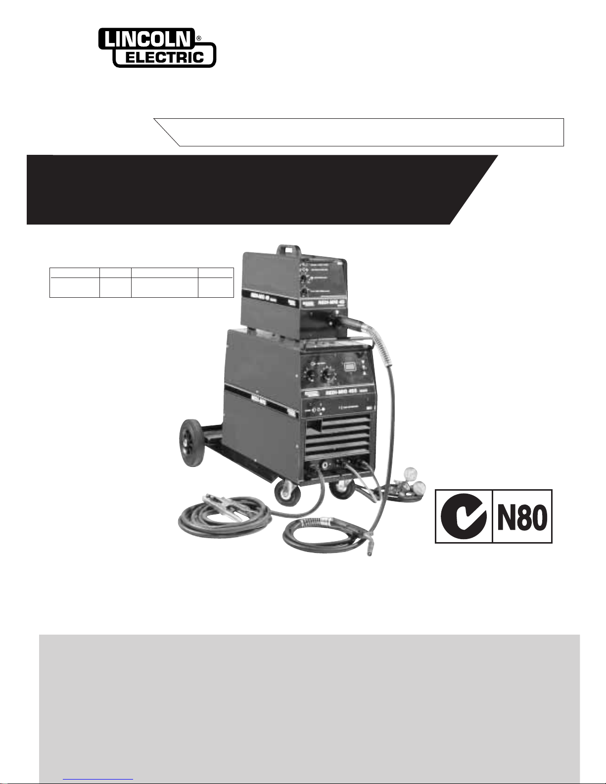
Part No. Code Description Volts
KA1443-2 F948 REDI-MIG 455 415
Remote
This manual applies to
REDI-MIG 455 Remote
Semi Automatic Arc Welding Machine
EMC Compliant
Page 2
Page 2 REDI-MIG 455 Remote IMA 603
PROTECT YOURSELF AND OTHERS FROM POSSIBLE SERIOUS INJURY OR DEATH. READ AND UNDERSTAND BOTH
THE SPECIFIC INFORMATION GIVEN IN THE OPERATING MANUAL FOR THE WELDER AND/OR OTHER EQUIPMENT
TO BE USED AS WELL AS THE FOLLOWING GENERAL INFORMATION.
ARC WELDING SAFETY PRECAUTIONS
1. a. The electrode and work (or ground) circuits are
electrically “hot” when the welder is on. Do not touch
these “hot” parts with your bare skin or wet clothing.
Wear dry, hole-free gloves to insulate hands.
b. In semi-automatic and automatic wire welding, the
electrode, electrode reel, welding head and nozzle or
semi-automatic welding gun are also electrically “hot”.
c. Insulate yourself from work and ground using dry
insulation. When welding in damp locations, on metal
framework such as floors, gratings or scaffolds, and
when in positions such as sitting or Lying, make certain
the insulation is large enough to cover your full area of
physical contact with work and ground.
d. Always be sure the work cable makes a good electrical
connection with the metal being welded. The
connection should be as close as possible to the area
being welded.
e. Ground the work or metal to be welded to a good
electrical (earth) ground.
f. Maintain the electrode holder, work clamp, welding
cable and welding machine in good, safe operating
condition. Replace damaged insulation.
g. Never dip the electrode holder in water for cooling.
h. Never simultaneously touch electrically “hot” parts of
electrode holders connected to two welders because
voltage between the two can be the total of the open
circuit voltage of both welders.
i. When working above floor level, protect yourself from
a fall should you get a shock.
j. Also see items 4c and 6.
2. a. Welding may produce fumes and gases hazardous to
health. Avoid breathing these fumes and gases. When
welding, keep your head out of the fume. Use enough
ventilation and/or exhaust at the arc to keep fumes and
gases away from the breathing zone. When welding
on galvanised, lead or cadmium plated steel and other
metals which produce toxic fumes, even greater care
must be taken.
b. Do not weld in locations near chlorinated hydrocarbon
vapours coming from degreasing, cleaning or spraying
operations. The heat and rays of the arc can react with
solvent vapours to form phosgene, a highly toxic gas,
and other irritating products.
c. Shielding gases used for arc welding can displace air
and cause injury or death. Always use enough
ventilation, especially in confined areas, to ensure
breathing air is safe.
d. Read and understand the manufacturer’ s instructions
for this equipment and the consumables to be used,
including the material safety data sheet (MSDS) and
follow your employer’s safety practices.
e. Also see Item 7b.
3. a. Use a shield with the proper filter and cover plates to
protect your eyes from sparks and the rays of the arc
when welding or observing open arc welding.
Headshield and filter lens should conform to AS
1674.2-1990 standards.
b. Use suitable clothing made from durable flame
resistant material to protect your skin and that of your
helpers from the arc rays.
c. Protect other nearby personnel with suitable non
flammable screening and/or warn them not to watch
the arc or expose themselves to the arc rays or to hot
spatter or metal.
4. a. Remove fire hazards from the welding area. If this is
not possible, cover them to prevent the welding sparks
from starting a fire. Remember that welding sparks
and hot materials from welding can easily go through
small cracks and openings to adjacent areas. Have a
fire extinguisher readily available.
b. Where compressed gases are to be used at the job
site, special precautions should be used to prevent
hazardous situations. Refer to AS1674 Parts 1 & 2
“Safety in Welding and Allied Processes”, WTIA
Technical Note 7 “Health and Safety in Welding” and
the operating information for the equipment being
used.
c. When not welding, make certain no part of the
electrode circuit is touching the work or ground.
Accidental contact can cause overheating and create
a fire hazard.
d. Do not heat, cut or weld tanks, drums or containers
until the proper steps have been taken to insure that
such procedures will not cause flammable or toxic
vapours from substances inside. These can cause an
explosion even though the vessel has been “cleaned”.
For information purchase AS 1674-1990.
e. Vent hollow castings or containers before heating,
cutting or welding. They may explode.
f. Sparks and spatter are thrown from the welding arc.
Wear oil free protective garments such as leather
gloves, heavy shirt, cuffless trousers, high shoes and
a cap over your hair. Wear ear plugs when welding out
of position or in confined places. Always wear safety
glasses with side shields when in a welding area.
g. Connect the work cable to the work as close to the
welding area as possible. Work cables connected to
the building framework or other locations away from
the welding area increase the possibility of the welding
current passing through lifting chains, crane cables or
other alternate circuits. This can create fire hazards or
overheat lifting chains or cables until they fail.
h. Also see Item 7c.
ELECTRIC SHOCK can kill
FUMES AND GASES
can be dangerous
ARC RAYS can burn
WELDING SPARKS can
cause fire or explosion
Page 3
IMA 603 REDI-MIG 455 Remote Page 3
5. a. Use only compressed gas cylinders containing the
correct shielding gas for the process used and
properly operating regulators, designed for the gas
and pressure used. All hoses, fittings, etc. should be
suitable for the application and maintained in good
condition.
b. Always keep cylinders in an upright position and
securely chained to an undercarriage or fixed support.
c. Cylinders should be located :
• Away from areas where they may be struck or
subjected to physical damage.
• A safe distance from arc welding or cutting
operations and any other source of heat, sparks
or flame.
d. Never allow the electrode, electrode holder, or any
other electrically “hot” parts to touch a cylinder.
e. Keep your head and face away from the cylinder valve
outlet when opening the cylinder valve.
f. Valve protection caps should always be in place and
hand-tight except when the cylinder is in use or
connected for use.
g. Read and follow the instructions on compressed gas
cylinders and associated equipment, and AS 2030
Parts 1 & 2.
6. a. Turn off input power using the disconnect switch at the
fuse box before working on the equipment.
b. Install equipment in accordance with the SAA Wiring
Rules, all local codes and the manufacturer’s
recommendations.
c. Ground the equipment in accordance with the SAA
Wiring Rules and the manufacturer’s
recommendations.
7. a. Turn the engine off before troubleshooting and
maintenance work unless the maintenance
work requires it to be running.
b. Operate engines in open, well ventilated
areas or vent the engine exhaust fumes
outdoors.
c. Do not add fuel near an open flame,
welding arc or when the engine is running.
Stop the engine and allow it to cool before
refuelling to prevent spilled fuel from
vaporizing on contact with hot engine parts
and igniting. Do not spill fuel when filling
tank. If fuel is spilled, wipe it up and do not
start engine until fumes have been
eliminated.
d. Keep all equipment, safety guards, covers
and devices in position and in good repair.
Keep hands, hair, clothing and tools away
from V-belts, gears, fans and all other
moving parts when starting, operating or
repairing equipment.
e. In some cases it may be necessary to
remove safety guards to perform required
maintenance. Remove guards only when
necessary and replace them when the
maintenance requiring their removal is
complete. Always use the greatest care
when working near moving parts.
f. Do not put your hands near the engine fan.
Do not attempt to override the governor or
idler by pushing on the throttle control rods
while the engine is running.
g. To prevent accidentally starting petrol
engines while turning the engine or welding
generator during maintenance work,
disconnect the spark plug wires, distributor
cap or magneto wire as appropriate.
h. To avoid scalding do not remove the
radiator pressure cap when the engine is
hot.
CYLINDER may explode if
damaged
FOR ELECTRICALLY
powered equipment
FOR ENGINE
powered equipment
HAVE ALL INSTALLATIONS, OPERATION, MAINTENANCE AND REPAIR WORK PERFORMED BY QUALIFIED PEOPLE
HOW TO ORDER REPLACEMENT PARTS
To ensure that you receive the correct replacement part the following procedure should be followed:
1. Quote Serial Number and Code Number.
2. Quote the Description, Item Number and Parts List Number of the desired part. When ordering parts for items carrying brand
names of other companies, such as fan motors, drive shafts, etc., be sure to include the other company’s name and part number
and other relevant information.
3. Should the primary cord be damaged, a special cord is required, and is available from Lincoln Electric.
4. Parts should be ordered from Lincoln, its offices or the nearest Authorised Field Service Shop. (The “Lincoln Service Directory”
listing these shops geographically is available on request.)
Note: “Hardware” in the Lincoln Parts Lists are not Lincoln stock items but can be obtained via the Field Service Shop network.
Component parts of assemblies such as stator coils or armature coils, etc., which require electrical testing or locating fixtures are not
considered replaceable items. This is to ensure that the customer receives parts which will keep the welder in the best operating condition.
BUY ONLY GENUINE REPAIR PARTS
For more detailed information it is strongly recommended that you purchase a copy of “Safety in Welding and Cutting - ANSI Standard Z
49.1” and WTIA Technical Note 7. All WTIApublications and ANSI/AWS Standards are available from the Welding Technology Institute of
Australia, P.O. Box 6165, Silverwater NSW 2128. For copies of various Australian Standards contact your local S.A.A. office.
Page 4

Page 4 REDI-MIG 455 Remote IMA 603
WELDING, EMF & PACEMAKERS
All welders should follow safe practices that minimise their
exposure to electric and magnetic fields (EMF).
For welders wearing implanted pacemakers, safe welding
practices are particularly important and additional procedures
should be followed by those who have decided to continue to
weld. (Hopefully in keeping with a doctor’s advice).
The following procedures will not eliminate exposure to EMF or
the possibility of arc welding having an effect on a pacemaker,
however if followed, they will significantly reduce exposure to
electric and magnetic fields. Electric and magnetic fields are
created any time electric current flows through a conductor,
however it is not clear whether such exposure affects ones
health.
Some researchers have reported that exposure to EMF may
cause leukemia or other illnesses. These claims originally arose
in relation to high voltage electric power lines and are very much
in dispute in the medical and scientific arena, however the best
advice is to minimise your exposure to EMF to protect your health
should doctors eventually decide there is a risk.
There are four fundamental facts about EMF:
• With direct current (DC), the field strength is relatively
constant and does not change.
• With alternating current (AC), the field strength constantly
changes.
• The greater the current flow, i.e. the higher the amps, the
stronger the field created by the current
• The closer the conductor or electrical device is to the body,
the greater the exposure to the field.
Minimising exposure
All welders should use the following procedures to minimise EMF
exposure.
• Route electrode or gun and work cables together. Secure
them with tape if possible.
• Never coil the electrode lead around your body.
• Do not place your body between the electrode and work
cables. If your electrode cable is on your right side the work
cable should also be on your right side.
• Connect the work cable to the work piece as close as
possible to the area being welded. (This is also a good
practice to eliminate a common problem on welding - a
poor work connection.
• Do not work next to the welding power source.
Welders with pacemakers
There is no question that the fields in arc welding can interfere
with a pacemakers function. Generally the interference does not
permanently damage the pacemaker. Once the wearer leaves the
arc welding environment or stops welding, the pacemaker returns
to normal functioning. The welding arc has little or no effect on the
operation of some pacemakers, especially designs that are bipolar or designed to filter out such interference.
For a welder or anyone working around electrical equipment the
selection of a pacemaker is very important. Get a doctor’s advice
about which pacemaker is the least sensitive to interference from
welding while still being medically suitable.
In addition to the normal safety precautions, the following
additional procedures should be adopted by welders with
pacemakers.
• Use gas welding when the application is suitable.
• Use the lowest current setting appropriate for the
application. Do not exceed 400 amps. Low current
(75-200 amps) direct current (DC) welding should be used
if arc welding is necessary. Do not TIG weld with high
frequency.
• Do not use repeated, short welds. Wait about ten seconds
between stopping one weld and starting the next. When
having difficulty starting an electrode, do not re-strike the
rod repeatedly.
• If you feel light headed, dizzy or faint, immediately stop
welding. Lay the electrode holder down so that it does not
contact the work and move away from any welding being
performed. Arrange your work in advance so that, if you
become dizzy and drop the electrode holder, the electrode
holder will not fall on your body or strike the work.
• Do not work on a ladder or other elevated position or in a
cramped, confined place.
• Do not work alone. Work only in the presence of an
individual who understands these precautions and the
possible effect welding may have on your pacemaker.
• Do not work near spot welding equipment.
• If you have a pacemaker and wish to continue arc welding,
discuss this and any other questions you may have with
your physician and follow his or her advice. The doctor may
wish to contact the pacemaker manufacturer for a
recommendation. As mentioned before, the design of the
pacemaker significantly affects the degree to which it is
subject to interference from a welding circuit. Do not rely on
the fact that you know another welder with a pacemaker
who has welded for years without experiencing a problem.
That welder and his or her pacemaker may be quite
different from you and your pacemaker.
Page 5

IMA 603 REDI-MIG 455 Remote Page 5
Conformance
Products displaying the C-Tick mark are in conformity with
Australian/New Zealand requirements for Electromagnetic
Compatibility (EMC). They are:
• manufactured in conformity with Australian/New Zealand
Standard (Emission):- AS/NZS 3652 ‘Electromagnetic
Compatibility - Arc Welding Equipment’ (Identical to and
reproduced from British Standard EN 50199)
• for using with other Lincoln Electric/LiquidArc equipment.
• designed for industrial and professional use.
Introduction
All electrical equipment generates small amounts of
electromanetic emission. Electrical emission may be transmitted
through power lines or radiated through space, similar to a radio
transmitter. When emissions are received by other equipment,
electrical interference may result. Electrical emissions may effect
many kinds of electrical equipment: other nearby welding
equipment, radio and TV transmitters and receivers, numerical
controlled machines, telephone systems, computers, etc. Be
aware that interference may result and extra precautions may be
required when a welding power source is used in a domestic
establishment.
Installation and Use
The purchaser/user is responsible for installing and using the
welding equipment according to the manufacturer’s instructions.
If electromagnetic disturbances are detected then it shall be the
responsibility of the purchaser/user of the welding equipment to
resolve the situation with the technical assistance of the
manufacturer. In some cases this remedial action may be as
simple as earthing (grounding) the welding circuit (see note
below). In other cases it could involve constructing an electromagnetic screen enclosing the power source and the work
complete with associated input filters. In all cases electromagnetic disturbances must be reduced to the point where they are no
longer troublesome.
Note: The welding circuit may or may not be earthed for safety
reasons according to national codes. Changing the earthing
arrangements should only be authorised by a person who is
competent to assess whether the changes increase the risk of
injury, eg. by allowing parallel welding current return paths which
may damage the earth circuits of other equipment.
Assessment of Area
Before installing welding equipment the purchaser/user shall
make an assessment of potential problems in the surrounding
area.
The following shall be taken into account:
a. Other supply cables, control cables, signalling and
telephone cables above, below and adjacent to the welding
equipment;
b. Radio and television transmitters and receivers;
c. Computer and other control equipment;
d. Safety critical safety equipment, eg. guarding of industrial
equipment;
e. The health of people around, eg. the use of pacemakers
and hearing aids;;
f. Equipment used for calibration or measurement;
g. The immunity of other equipment in the environment. The
purchaser/user shall ensure that other equipment being
used in the environment is compatible. This may require
additional protection measures;
h. The time of the day that welding or other activities are to be
carried out.
The size of the surrounding area to be considered will depend on
the structure of the building and other activities that are taking
place. The surrounding area may extend beyond the boundaries
of the premises.
Methods of Reducing Emissions
Mains Supply
Welding equipment should be connected to the mains supply
according to the manufacturer’s recommendations.If interference
occurs, it may be necessary to take additional precautions such
as filtering the mains supply. Consideration should be given to
shielding the supply cable of permanently installed welding
equipment in metallic conduit or equivalent. Shielding should be
electrically continuous throughout its length. The shielding should
be connected to the welding power source so that good electrical
contact is maintained between the conduit and the welding power
source enclosure.
Maintenance of the Welding Equipment
The welding equipment should be routinely maintained according
to the manufacturer’s recommendations. All access and service
doors and covers should be closed and properly fastened when
the welding equipment is in operation. The welding equipment
should not be modified in any way except for those changes and
adjustment covered in the manufacturer’s instructions. In
particular, the spark gaps of arc initiation and stabilising devices
should be adjusted and maintained according to the
manufacturer’s recommendations.
Welding Cables
The welding cables should be kept as short as possible and
should be positioned close together, running at or close to the
floor level.
Equipotential Bonding
Bonding of all metallic components in the welding installation and
adjacent to it should be considered. However, metallic
components bonded to the work piece will increase the risk that
the operator could receive a shock by touching these metallic
components and the electrode at the same time. The operator
should be insulated from all such bonded metallic components.
Earthing of the workpiece
Where the workpiece is not bonded to earth for electrical safety,
nor connected to earth because of its size and position, eg. ship’s
hull or building steelwork, a connection bonding the workpiece to
earth may reduce emissions in some, but not all instances. Care
should be taken to prevent the earthing of work pieces increasing
the risk of injury to users, or damage to other electrical
equipment. Where necessary, the connection of the workpiece to
earth should be made by direct connection to the workpiece, but
in some countries where direct connection is not permitted, the
bonding should be achieved by suitable capacitance, selected
according to national regulations.
Screening and Shielding
Selective screening and shielding of other cables and equipment
in the surrounding area may alleviate problems of interference.
Screening of the entire welding installation may be considered for
special applications.*
* Portions of the preceding text are contained in AS/NZS3652:
‘Electromagnetic Compatibility - Arc Welding Equipment’.
INSTRUCTIONS FOR ELECTROMAGNETIC COMPATIBILITY
This welding machine must be used by trained operators
only. Read this manual carefully before attempting to use
the welding machine.
WARNING
Page 6
Page 6 REDI-MIG 455 Remote IMA 603
Thank You
for selecting a QUALITY product by Lincoln Electric. We want you to
take pride in operating this Lincoln Electric Company product - as much
pride as we have in bringing this product to you!
Please Examine Carton and Equipment for Damage Immediately
When this equipment is shipped, title passes to the purchaser upon receipt by the carrier. Consequently, claims for
material damaged in shipment must be made by the purchaser against the transportation company at the time the
shipment is received.
Please record your equipment identification information below for future reference. This information can be found
on your machine nameplate.
Model Name & Number _______________________________________________
Code & Serial Number ________________________________________________
Date of Purchase ____________________________________________________
Read this Operator’s Manual completely before attempting to use this equipment. Save this manual and keep it
handy for quick reference. Pay particular attention to the Safety Instructions we have provided for your protection. The
level of seriousness to be applied to each is explained below:
This statement appears where the information must be
followed exactly to avoid serious personal injury or loss of life.
WARNING
This statement appears where the information must be
followed to avoid minor personal injury or damage to this
equipment.
CAUTION
Page 7

IMA 603 REDI-MIG 455 Remote Page 7
Page
Section 1 INSTALLATION 8
1.1 Location 8
1.2 Connection to Mains Supply 8
1.3 Shielding Gas Supply (for the Gas Metal Arc Welding Process) 9
1.4 Gun and Cable Installation 9
1.5 Output Polarity Connection 9
Section 2 OPERATING INSTRUCTIONS 10
2.1 Duty Cycle 10
2.2 Control Panel 10
Section 3 SETTING UP FOR WELDING 11
Section 4 WELDING 13
4.1 Changing Electrode Size and Type 13
4.2 Adjusting Spool Tension 13
Section 5 LEARNING TO WELD 13
5.1 The Arc-Welding Circuit 13
5.2 The Self-Shielded (Gasless) FCAW Welding Arc 14
5.3 The GMAW (MIG) Welding Arc 14
5.4 Process Selection 14
5.5 Common Metals 14
5.6 Machine Set Up for the Self-Shielded (Gasless) FCAW Process 14
5.7 Welding Techniques for the Self-Shielded (Gasless) FCAW Process 15
5.8 Machine Set Up for the GMAW (MIG) and Gas-Shielded FCAW Processes 16
5.9 Welding Techniques for the GMAW (MIG) Process 16
5.10 Joint Types and Positions 17
5.11 Butt Welds 17
5.12 Penetration 17
5.13 Fillet Welds 18
5.14 Welding in the Vertical Position 18
5.15 Vertical-Up and Overhead Welding 18
5.16 Vertical-Down Welding 18
5.17 Troubleshooting Welds 18
Section 6 - MAINTENANCE 19
6.1 Routine Maintenance 19
6.2 Gun and Cable Maintenance 19
6.3 Gun Tips and Nozzles 19
6.4 Input Lead 19
6.5 Liner Removal, Installation and Trimming Instructions
for REDI-MIG 4 Torch 20
Section 7 ACCESSORIES 20
Section 8 GROUND TEST PROCEDURE 20
Section 9 TROUBLESHOOTING 21
PARTS LIST REDI-MIG 455 Remote 23
WIRING DIAGRAM REDI-MIG 455 Remote 28
PARTS LISTS REDI-MIG 4D Remote Wire Feeder 29
WIRING DIAGRAM REDI-MIG 4D Remote Wire Feeder 33
WIRE DRIVE ASSEMBLY 34
PARTS LISTS REDI-MIG 2 & 4 TORCHES 36
INDEX
Page 8
Machine Installation
1.1 Location
Place the welder where clean cooling air can freely
circulate in through the front louvers and out through the
rear louvers. Dirt, dust or any foreign material that can be
drawn into the welder should be kept at a minimum. Failure
to observe these precautions can result in excessive
operating temperatures and nuisance thermostat trips.
1.2 Connection to Mains Supply
Before connecting the machine to the mains supply check
that the voltage and current capacity correspond to the
machine voltage and rated input current. Use a fuse or C/B
per AS3000 or local wiring rules.
The machine is supplied with an input lead fitted.
Have a qualified electrician fit a suitable input plug.
1.3 Shielding Gas Supply (For the Gas Metal
Arc Welding Process)
Refer “Safety in welding and cutting” - ANSI Standard Z491 and WTIA Technical Note 7, available from the Welding
Technology Institute of Australia.
Obtain cylinder of appropriate type shielding gas for the
process being used.
Page 8 REDI-MIG 455 Remote IMA 603
• Turn the input power off at the
disconnect switch before installing
or servicing this machine.
• Do not touch electrically
“hot” parts such as output
terminals or internal wiring.
• Connect earthing screw ( ) to
a good earth ground.
• Do not operate with covers
removed.
• Turn power switch “off” before
connecting or disconnecting
cables or other equipment.
WARNING
HIGH
VOLTAGE
can kill
Only qualified personnel should install or service this equipment.
PRODUCT DESCRIPTION
The REDI-MIG 455 Remote offers a remote wire feeder and a separate Constant Voltage DC arc welding machine. It combines a solid state
power source with electronically controlled wire feeding equipment.
Excellent arc characteristics are provided for both gas shielded and self shielded welding within its current range.
Standard features include output volt and amp meter, a spot timer, gas purge facilities, wire inch, burnback control, a dual position 2 or 4
step trigger interlock, a REDI-MIG 4 MIG gun, a Harris 801 regulator/flowmeter and gas hose, a 5m ground cable assembly, a 5m long
input lead and a twin cylinder undercarriage on which gas cylinders can be mounted.
Section 1 - INSTALLATION
Never connect the green/yellow conductor to any of the
active supply lines from the mains. This conductor is to
earth the machine as required by Electrical Regulations.
Once the above has been followed the machine can be
plugged into the mains outlet.
CAUTION
* Dimensions do not include Wire Feeder
Model
REDI-MIG 455 Remote
Part No. KA1443-2
Maximum Open Circuit Voltage 47V
Output Current Range 30 to 455A
Duty Cycle 35% 60%
Rated Output 455A/36.5V 350A/31.5V
Rated Input AS1966 415V 3ph 50Hz 19 amps
Wire Speed Range 1-20 m/min
Weight (complete with u/c) 148 kg
H x W x L (mm) Over handle
cylinder tray & wheels
775 x 670 x 1050 mm*
Operating Temperature -20˚C to 40˚C
Specifications
CYLINDER may explode if
damaged
Page 9
IMA 603 REDI-MIG 455 Remote Page 9
1. Set gas cylinder on rear platform of the machine. Hook chain in
place to secure cylinder to rear of welder.
2. Remove the cylinder cap. Inspect the cylinder valve for
damaged threads, dirt and dust. For cylinders having an
external thread fitting, remove any dust and dirt from the
threads with a clean cloth.
DO NOT ATTACH THE REGULATOR/FLOWMETER IF
OIL, GREASE OR CYLINDER VALVE DAMAGE IS
PRESENT. OIL OR GREASE IN THE PRESENCE OF
HIGH PRESSURE OXYGEN IS EXPLOSIVE! Inform your
gas supplier of this condition.
3. Stand to one side away from the outlet and open the
cylinder valve for an instant. This blows away any dust or
dirt which may have accumulated in the valve outlet.
4. Inspect the regulator/flowmeter for damaged threads and
seals, dirt and dust. Remove dust and dirt with a clean
cloth.
DO NOT USE THE REGULATOR/FLOWMETER IF
DAMAGE IS PRESENT! Have an authorised repair station
repair any damage.
5. Attach the regulator/flowmeter to the cylinder valve and
tighten the union nut(s) securely with a spanner.
6. Attach the machines inlet gas hose to the outlet fitting of the
regulator/flowmeter, and tighten the union nut securely with
a spanner.
7. Before opening the cylinder valve, turn the regulator
adjusting knob counter-clockwise until the adjusting spring
pressure is released.
8. Open the cylinder valve slowly a fraction of a turn. When
the cylinder pressure gauge pointer stops moving, open the
valve fully.
9. The regulator/flowmeter is adjustable. Set it for the flow rate
recommended for the procedure and process being used
before starting to weld.
1.4 Gun and Cable Installation
The REDI-MIG 4 MIG gun and cable provided with the
machine has a factory fitted 0.9-1.2mm liner and a 1.2mm
contact tip.
1. Lay the cable out straight.
2. Make sure all pins on the gun cable connector are
aligned with the proper mating sockets on the front
panel gun connector and then join the connectors and
tighten the hand nut on the gun cable connector.
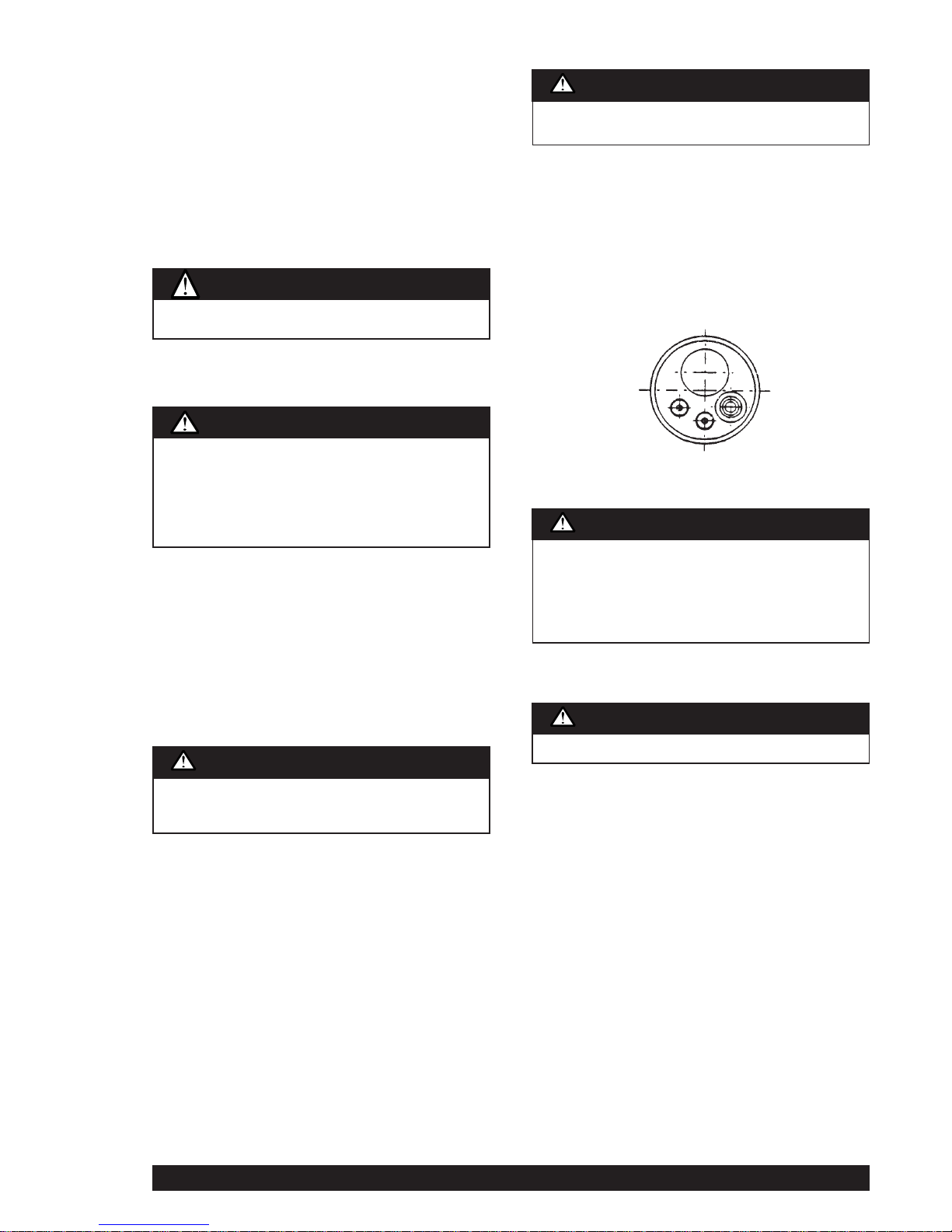
Note: If a gun and cable other than the supplied gun is to
be used, it must conform to standard European-style
connector specifications. See diagram under.
The gun trigger switch must be capable of switching 10
milliamps at 60 volts DC—resistive.
1.5 Output Polarity Connection
The REDI-MIG 4D is connected to the REDI-MIG 455
Remote power source via a control/ electrode/gas cable
assembly. The electrode cable is connected to the required
female Twist-Mate terminal on the front of the REDI-MIG
455 Remote power source.
The control cable connects to the plug on the front panel
between the positive and negative output connections of
the REDI-MIG 455 Remote power source.
The gun polarity can be changed by placing the electrode
cable to the required output connection on the front of the
REDI-MIG 455 Remote Power Source eg. for electrode ()ve, connect the electrode cable to the (-)ve output
connection.
Connect the work lead to the other output connection.
(See connection diagrams Page 11).
Each output connection is a Twist-Mate terminal. To
connect the output terminals, insert the correct mating
Twist-Mate plug and twist clockwise to secure. Twist anticlockwise and pull gently to release the Twist-Mate plug.
Gas under pressure is explosive. Always keep gas
cylinders in an upright position and always keep chained
to undercarriage or stationary support. Refer “Safety in
Welding and Cutting” - ANSI Standard Z49-1 and WTIA
Technical Note 7 available from the Welding Technology
Institute of Australia.
WARNING
Never stand directly in front of or behind the
regulator/flowmeter when opening the cylinder valve.
Always stand to one side.
WARNING
The gun trigger switch connected to the gun trigger
control cable must be a normally open, momentary switch.
The terminals of the switch must be insulated from the
welding circuit. Improper operation of, or damage to, the
machine might result if this switch is common to an
electrical circuit other than the machine trigger circuit.
CAUTION
Turn the welder power switch off before installing gun and
cable.
WARNING
Turn the welder power switch off before changing polarity.
WARNING
Be sure to keep your face away from the valve outlet when
“cracking” the valve.
WARNING
Page 10
Page 10 REDI-MIG 455 Remote IMA 603
2.1 Duty Cycle
The machine is rated at the following duty cycles:
(1) Based on 10 min. time period (i.e., for 60% duty cycle, it is
6 minutes actual welding and 4 minutes with no welding
output, but with the input power remaining on keeping the
cooling fan operative.)
2.2 Control Panel
a) Power Switch
The mains power switch is a two position toggle switch and
is marked “POWER”. When the toggle switch is pressed
downwards to the “O” position the input mains power is
switched off.
b) Pilot Light
This light illuminates when the input mains power is
switched on.
c) Volts Control
The output voltage is controlled by two rotary switches.
One rotary switch provides three “course” voltage settings.
The other rotary switch provides the user with a selection
of ten fine voltage settings. The selection between these
two rotary switches allows the user to select any one of
thirty welding voltages.
The Coarse Voltage rotary switch is marked with the three
coarse ranges A, B and C.
A) is the low range which supplies voltage from 16 to
18.5V.
B) is the medium range which supplies voltage from 18.5
to 24V.
C) is the high range which supplies voltage from 24 to
36.5V.
The fine voltage rotary switch is marked with the ten
welding voltages a, b, c, d, e, f, g, h, i and j.
d) Wire Feed Speed Control *
Use this control to adjust the speed at which the electrode
wire feeds when welding. This is in effect a current control
as the power source will deliver the current necessary to
melt the wire. The higher the speed, the more current will
be required. Wire feed speed range is approximately 1 to
20 meters/min (40 to 790 inches/min.).
Operation of the gun trigger switches the wire feed motor
on and off, depending upon the trigger mode setting. The
wire feed motor is dynamically braked to minimise wire
overrun after welding has ceased.
Welding voltage is available immediately the gun trigger is
operated. When welding is stopped there is a delay to allow
the electrode to burn back slightly and prevent sticking in
the crater. [See Burnback Control 2.2 f)]
e) Inductance Settings
The inductance can be changed by changing the position
of the negative output connection. The negative output
connection closest to the side panel work is the High
Inductance Negative Output Connection.
The High Inductance Negative Output Connection is
symbolised by “ “.
The High Inductance Negative Output Connection is more
suitable when a soft arc is preferred.
The negative output connection furthest from the side
panel work is the Low Inductance Negative Output
Connection.
The Low Inductance Negative Output Connection is
symbolised by “ “.
The Low Inductance Negative Output Connection is more
suitable when a crisp arc is preferred.
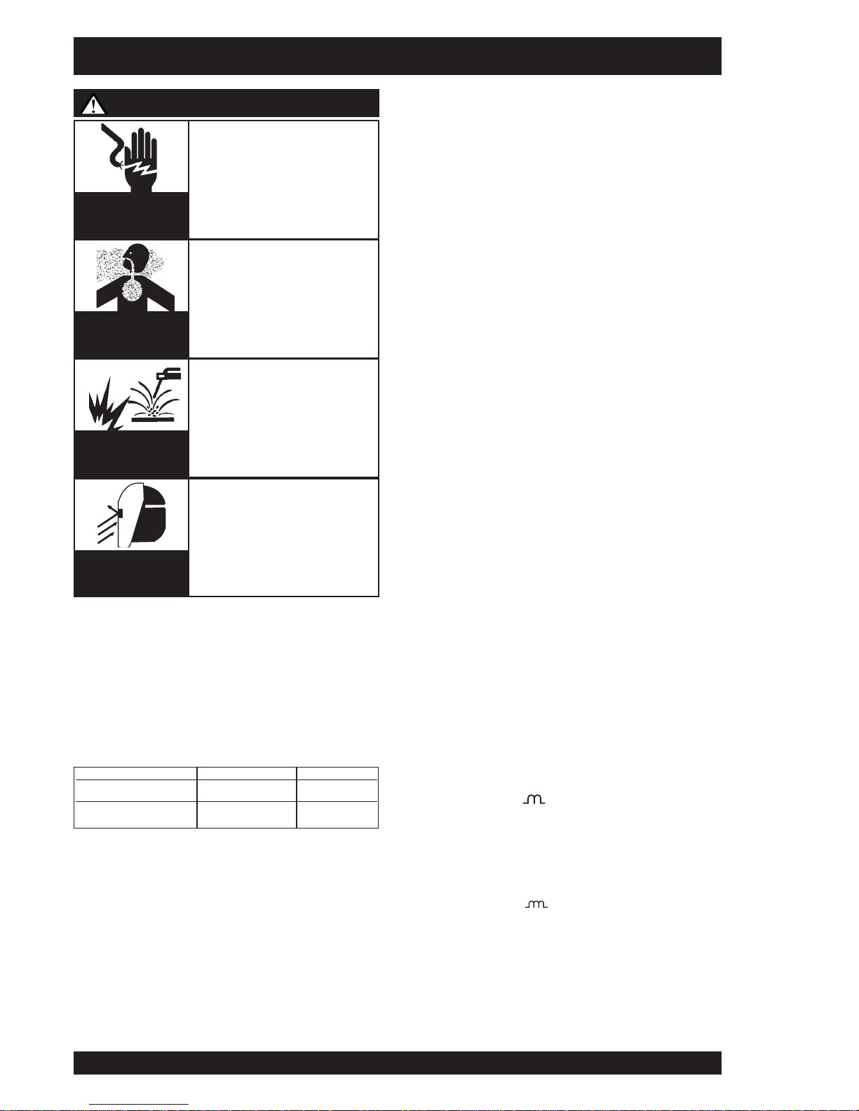
WARNING
ELECTRIC
SHOCK
can kill
FUMES AND
GASES can be
dangerous
WELDING SPARKS
can cause fire or
explosion
ARC RAYS
can burn
• Do not touch electrically live
parts or electrode with skin or
wet clothing.
• Insulate yourself from work and
ground.
• Always wear dry insulating
gloves.
• Keep your head out of fumes.
• Use ventilation or exhaust to
remove fumes from breathing
zone.
• Keep flammable material away.
• Do not weld upon containers
which have held combustibles.
• Wear eye, ear and body
protection.
IMPORTANT SAFETY NOTE: In 2T mode {refer 2.2 (i)}, this DC
Constant Voltage wire welder provides “COLD” electrode when
the gun trigger is not operated. Conversely, the output terminals
are “LIVE” when the gun trigger is “activated” when pressed in 2T
mode, or triggered on in 4T mode.
Section 2 - OPERATING INSTRUCTIONS
Duty Cycle
(1)
Amps Volts
35% 455 36.5
60% 350 31.5
Page 11

IMA 603 REDI-MIG 455 Remote Page 11
f) Burnback Control *
This control is located in the wire feed bay. The burnback
control adjusts the time period from when the drive motor
stops until the power source and gas solenoid are switched
off. [Approximately 0.1 seconds (when fully counterclockwise) to approximately 1.1 seconds (when fully clockwise)].
The purpose of the burnback control is to prevent the
electrode wire sticking in the weld crater at the finish of the
weld.
g) Spot Welding *
In spot welding mode, welding takes place for a pre-set
time and then stops automatically. Welding time is
adjustable between 0.5 sec. and 4 sec. by operation of the
spot weld control on the front panel. There is a positive
click in the extreme anti-clockwise position to indicate that
the spot weld feature is “off”.
h) Gas Purge/Wire Inch *
Use the gas purge momentry toggle switch to operate the
gas solenoid to purge air from the hose after connecting a
new gas cylinder. Gas purge will only operate while the
toggle switch is held upwards.
Use this same toggle switch to operate the wire feed motor
and “cold” inch the wire, by pushing the toggle switch
downwards.
i) 2 Step/4 Step Trigger Operation *
Atwo position toggle switch on the front panel provides two
modes of operation of the gun trigger. In 2 Step mode, the
gun trigger is pressed to start welding and released to stop.
In 4 Step mode, pressing the gun trigger only operates the
gas solenoid, allowing shielding gas to flow. Releasing the
trigger activates the contactor which starts the wire feed
motor and connects welding current to the wire so that
welding may commence. To stop welding, the trigger must
again be operated; pressing it stops the wire feed, activates
the burn back time delay and opens the contactor after the
pre-set burn back time. Releasing the trigger stops the gas
flow.
To recommence welding, the above cycle must be
repeated.
j) Over temperature light
Indicates that the thermostats have operated to protect unit
from over temperature.
* Mounted on REDI-MIG 4D wire feeder (Burnback is mounted in the
wire bay area).
The following items are required:
1) A reel of wire of suitable size and type .
2) A suitable gun and cable assembly with a “Euro” connector
and the correct tip and, if necessary gas nozzle for the
consumable being used. (A REDI-MIG 4 gun is supplied).
3) Correct drive rolls for the wire size and type to be used. The
wire feeder is supplied with a 0.9/1.2mm solid wire feed roll
as standard; drive rolls for other types and sizes are
available as spare parts. (see table on page 13).
4) A work return cable and clamp.(supplied)
5) Normal welding accessories including helmet or hand
shield with suitable lens, gloves etc.
6) If a gas shielded process is to be used, a cylinder of
appropriate gas is required. (Regulator/flowmeter and hose
are supplied.) If gas shielding is required, connect the gas
per Section 1.3 of this manual.
Remember that gas cylinders may explode if damaged, so ensure
that all gas cylinders are securely mounted.
Ensure that the correct type and size wire feed rolls are fitted. In
replacing wire feed rolls, ensure that the key and keyway are
correctly positioned and tighten the knurled locking screw
securely.
It is best to remove the gun before loading a new spool of wire.
Fit a spool of appropriate wire onto the 50mm spool hub so that,
as wire is fed, the spool turns clockwise. Carefully release the end
of the wire from the spool ensuring that the released end is held
to stop the wire from unravelling. Cut off the end kink to give a
smooth straight end of wire.
Obtain a gap between the wire feed roll and the pressure roll by
lifting the cam latch. Feed the wire end into the guide tube,
between the drive rolls, and into the “Euro” connector guide until
it protrudes about 20mm out of the front of the “Euro” connector.
Close the drive rolls by lowering the cam latch ensuring the rolls
firmly hold the wire. Ensure the wire is correctly aligned between
all four rolls and that the drive roll gear teeth mesh correctly before
lowering the cam latch. Poor alignment of wire or drive roll gear
teeth may cause wire slipping.
Refit the gun and cable assembly onto the “Euro” connector by
slipping the end of wire into the cable wire hole. Tighten the “Euro”
connector lock ring. (Refer Section 1.4 - Gun and Cable
Installation for further instructions).
Connect the control cable (a 4 pin male plug attached to the wire
feeder) to the 4 pin female plug on the front of the REDI-MIG 455
Remote power source, between the positive and negative output
connections.
Activate the power source, set the wire feed speed to 4 on the dial
and press the Gas Purge/Wire Inch toggle switch downwards. The
wire feed roll should turn, feeding the wire further up the gun and
cable assembly. (Adjust the tension on the drive roll cam latch so
that the wire feeds smoothly. Do not overtighten).
Ensure there are no kinks or sharp bends in the gun cable and
hold the Gas Purge/Wire Inch toggle switch downwards until the
wire emerges from the gun. It is good practice to remove the tip
when first feeding a new coil of wire, then refitting the tip over the
wire and tightening.
Cut off the end of the wire leaving 10mm to 15mm stick-out from
the tip.
Select required polarity. See Section 1.5 - Output Polarity
Connection and diagrams below.
Section 3 - SETTING UP FOR WELDING
DC+
SETUP
DC-
SETUP
Gas Shielded Wires
Gasless Wires
Negative Output Stud
Work Lead
Positive Output Stud
To Wire Feeder
Positive Output Stud
Work Lead
Negative Output Stud
To Wire Feeder
Page 12
Page 12 REDI-MIG 455 Remote IMA 603
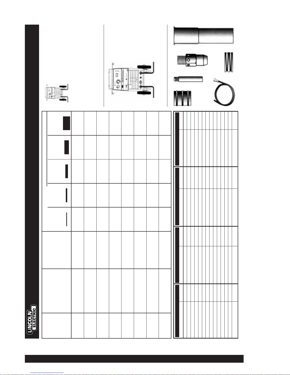
STEEL CONSUMABLES STAINLESS STEEL CONSUMABLES ALUMINIUM CONSUMABLES FLUX CORED CONSUMABLES
Part Part No. Part Part No. Part Part No. Part Part No.
Contact Tip 0.9mm MD 4-09 Contact Tip 0.9mm MD 4-09 Contact Tip 0.9mm MD 4-09A Contact Tip 0.9mm MD 4-09
Contact Tipt1.0mm MD 4-10 Contact Tipt1.0mm MD 4-10 Contact Tipt1.0mm MD 4-10A Contact Titp1.0mm MD 4-10
Contact Tipt1.2mm MD 4-12 Contact Tipt1.2mm MD 4-12 Contact Tip 1.2mm MD 4-12A Contact Tip 1.2mm MD 4-12
Contact Tipt1.6mm MD 4-16A Contact Tipt1.6mm MD 4-16
Contact Tipt1.7mm MD 4-16A
Gas Nozzle 16mm Ø MC 146 Gas Nozzle 16mm Ø MC 146 Gas Nozzle 16mm Ø MC 146 Gas Nozzle 16mm Ø MC 146
Insulator MQ 131 Insulator MQ 131 Insulator MQ 131 Insulator MQ 131
Gas Diffuser ME 20 Gas Diffuser ME 20 Gas Diffuser ME 20 Gas Diffuser ME 20
Drive Roll
‡
0.8,0.9mm AS4449-11 Drive Roll
‡
0.8,0.9mm AS4449-11 Drive Roll
‡
0.8,1.0mm AS4449-5 Drive Roll
‡
0.8,1.0mm AS4449-3
Drive R oll 0.9,1.2mm AS4449-8 Drive Ro ll 0.9,1.2mm AS4449-8 Drive Ro ll 0.9,1.2mm AS4449-12 Drive Ro ll 0.9,1.2mm AS4449-13
Drive R oll 1.0,1.2mm AS4449-2 Drive Ro ll 1.0,1.2mm AS4449-2 Drive Ro ll 1.2,1.6mm AS4449-6 Drive Ro ll 1.2,1.6mm AS4449-4
Liner 0.9-1.2mm GM226 Liner 0.9-1.2mm GM226 Liner Teflon 0.9-1.2mm GM230 Liner 0.9-1.2mm GM226
Drive Ro ll 1.2-1.6mm GM231
Aluminium Feeding Kit KA1440-3 Flux Cored Feeding Kit KA1441-3
PLATE THICKNESS
0.9mm 1.6mm 3.0mm 5.0mm 8.0mm +
21 gauge 16 gauge 10 gauge 6 gauge 1 gauge +
PROCESS WELDING WIRE SHIELDING GAS 0.032” 1/16” 0.134” 0.203” 0.300”
* Recommended Wire
0.9mm Dia
MIG
Solid Steel Wire Argon - CO2 blend Aa-3 Af-5 Bb-7 Bi-12 Cb-16
DC+
Lincoln L54/ L56 Ultra*
1.2mm Dia
MIG
Solid Steel Wire Argon - CO2 blend Af-4 Bc-6 Cc-11 Cd-12
DC+
Lincoln L54/ L56 Ultra*
1.2mm Dia
MIG
Solid Aluminium Wire Argon - 100% Aa-7 Ba-9 Be-12 Bh-15
DC+
Lincoln Super Glaze 5356*
1.6mm Dia
MIG
Solid Aluminium Wire Argon - 100% Ah-7 Be-9 Bh-11
DC+
Lincoln Super Glaze 5356*
1.2mm Dia
FCAW
Gasless Cored Wire Not Required Ab-3 Af-4 Ah-5 Bc-6
DC-
Lincoln Innershield NR212MP*
1.7mm Dia
FCAW
Gasless Cored Wire Not Required Ag-2 Bc-3 Be-4
DC-
Lincoln Innershield NR212MP*
1.2mm Dia
FCAW
Gas covered Cored Wire Argon - CO2 blend Bf-7 Bh-9 Cc-17
DC+
Lincoln Outershield 71M*
1.6mm Dia
FCAW
Gas Covered Cored Wire Argon - CO2 blend Bh-6 Ca-8 Ce-11
DC+
Lincoln Outershield 71M*
Suggested Settings for Welding with the REDI-MIG 455
INSULATOR
CONTACT TIP
GAS DIFFUSER
GAS NOZZLEDRIVE ROLLLINER
DC+
SETUP
(Gas Shielded
Wires)
DC-
SETUP
(Gasless Wires)
‡
Remote wire feeder requires 2 Drive rolls.
Negative Output Stud
Work Lead
Positive Output Stud
To Wire Feeder
Positive Output Stud
Work Lead
Negative Output Stud
To Wire Feeder
Page 13

IMA 603 REDI-MIG 455 Remote Page 13
Put into 2 Step trigger mode.
Select the output voltage required to suit the job by setting
the coarse and fine rotary voltage switches. (Refer to
REDI-MIG 455 Welding Guide suggested settings).
Before beginning welding, ensure the wire protrudes from
the gun tip by approximately 10-15mm. Ensure gas is
turned on for gas shielded processes. Ensure welding
shield and other protective clothing are in place. Present
the protruding electrode just off the work. Maintain a steady
grip on the gun, protect your eyes with a welding shield,
then press and hold the gun trigger to create the arc.
If it is necessary to adjust the weld voltage, stop welding
before changing either or both of the rotary voltage
switches.
Adjust the wire feed speed as necessary to suit the job. At
the completion of the weld, release the gun trigger and pull
the gun away from the work to stop the arc.
4 Step trigger mode should only be used for long welds by
experienced operators.
4.1 Changing Electrode Size and Type
When changing the electrode size or type, ensure the wire
feed drive roll is the correct size and type for the electrode.
Wire feed drive rolls have two grooves each of different
sizes. Ensure the roll is located by the key and keyway and
firmly secured by knurled screw.
When changing to aluminium welding a new drive roll,
cable liner and contact tip should be used.
All required equipment for aluminium welding is supplied in
the optional 1.2mm Aluminium Feeding Kit (KA1440-3).
When changing to cored wire welding, a new drive roll
should be used. All required equipment for cored wire
welding is supplied in the optional 1.2mm Flux Cored
Feeding Kit (KA1441-3).
Also check electrode polarity, as different processes may
require different polarities.
Note: Ensure that the correct gun liner and contact tip are
used for different wire sizes and processes. Change gun
liner as necessary. See Section 6.5 Liner Removal,
Installation and Trimming Instructions for REDI-MIG 4
Torch.
* Standard on REDI-MIG 455 Remote.
4.2 Adjusting Spool Tension
The spool should stop rotating when the wire feed roll
stops. Overrun of the spool can cause the coil of wire to
unravel. The spool hub should be tensioned so that it
neither drags nor overruns. The tension can be set by
adjusting the large nut inside the hub with a tube spanner.
Section 4 - WELDING
When the gun trigger is pressed (2 mode) or pressed and
released the first time (4 mode), the wire is at welding
voltage. The wire should never touch the case of the wire
feeder. If it does, it is possible for the wire to arc to the
case.
Any wire overrun should be avoided.
WARNING
Part No. Size (mm) Use with
AS4449-9 0.6 - 0.8 Solid Wire
AS4449-11 0.8 - 0.9 Solid Wire
AS4449-8 0.9 - 1.2 Solid Wire *
AS4449-2 1.0 - 1.2 Solid Wire
AS4449-5 0.8 - 1.0 Aluminium Wire
AS4449-12 0.9 - 1.2 Aluminium Wire
AS4449-6 1.2-1.6 Aluminium Wire
AS4449-3 0.8 - 1.0 Cored Wire
AS4449-13 0.9 - 1.2 Cored Wire
AS4449-4 1.2 - 1.6 Cored Wire
Available Drive Rolls
Section 5 - LEARNING TO WELD
No one can learn to weld simply by reading about it. Skill
comes only with practice. The following pages will help the
inexperienced operator to understand welding and develop
this skill.
5.1 The Arc-Welding Circuit
The operators knowledge of arc welding must go beyond
the arc itself. The operator must know how to control the
arc, and this requires a knowledge of the welding circuit
and the equipment that provides the electric current used
in the arc. The circuit begins where the gun cable is
attached to the welding machine. Current flows through the
gun cable, gun, and contact tip, to the wire and across the
arc. On the work side of the arc, current flows through the
base metal to the work cable and back to the welding
machine. This circuit must be complete for the current to
flow.
This machine’s welding circuit has a voltage output of 47
volts DC maximum. This voltage is quite low and is only
present when the gun trigger is depressed.
To weld, the work clamp must be tightly connected to clean
base metal. Remove paint, rust, dirt or oil as necessary and
connect the work clamp as close as possible to the area
you wish to weld. This helps prevent current from going
through an unwanted path. Avoid allowing the welding
circuit to pass through hinges, bearings, electronic
components, or similar devices that can be damaged.
Always disconnect electrical devices before welding upon
them.
Fumes and slag generated from electrodes recommended
for use with this welding machine can be toxic.
• Avoid contact with eyes and skin.
• Do not take internally.
• Keep out of reach of children.
• Follow all safety precautions found in this operating
manual.
The gun and cable assembly is held by the operator who
guides the automatically fed wire along the joint,
maintaining a contact tip to work distance of about 10 - 12
mm This is called electrical stickout. This electrical stickout
(ESO) must be properly maintained by the operator. The
electric arc is made in the gap between the work and the
tip end of a small diameter wire. When the power source is
properly set, the arc gap is maintained automatically.
Arc welding is a manual skill requiring a steady hand, good
physical condition, and good eyesight. The operator
controls the welding arc, and, therefore, the quality of the
weld made.
FUMES AND GASES can be
dangerous
Page 14

5.2 The Self-Shielded (Gasless)
FCAW Welding Arc (DC-)
Figure 1 illustrates the action taking place in the self
shielded gasless FCAW welding arc. It closely resembles
what is actually seen while welding.
The “arc stream” is seen in the middle of the picture. This
is the electric arc created by the electric current flowing
through the space between the end of the wire electrode
and the base metal. The temperature of this arc is about
3300°C, which is more than enough to melt metal.
The arc is very bright, as well as hot, and cannot be looked
at with the naked eye without risking painful injury. The very
dark lens, specifically designed for arc welding must be
used with the hand or face shield whenever viewing the arc.
The arc melts the base metal and actually digs into it much
as water through a nozzle on a garden hose digs into the
earth. The molten metal forms a molten pool or crater and
tends to flow away from the arc. As it moves away from the
arc, it cools and solidifies.
The function of the cored wire electrode is much more than
simply to carry current to the arc. The wire core is
composed of fluxes and/or alloying ingredients around
which a steel sheath has been formed. It is simply a stick
electrode turned inside out in a continuous wire form.
The cored wire melts in the arc and tiny droplets of molten
metal shoot across the arc into the molten pool. The wire
sheath provides additional filler metal for the joint to fill the
groove or gap between the two pieces of base metal.
The core materials also melt or burn in the arc and perform
several functions. They make the arc steadier, provide a
shield of smoke-like gas around the arc to keep oxygen
and nitrogen in the air away from the molten metal, and
provide a flux for the molten pool. The flux picks up
impurities and forms the protective slag on top of the weld
during cooling.
After running a weld bead, the slag may be removed with a
chipping hammer and wire brush. This improves
appearance and allows for inspection of the finished weld.
Machine size and output characteristics limit the size and
type of wire electrode which can be used.
5.3 The GMAW (MIG) Welding Arc (DC+)
Figure 2 illustrates the GMAW (MIG) welding arc. Solid
wire does not contain fluxes or ingredients to form its own
shielding and no slag forms to protect the molten weld
metal. For this reason, a continuous even flow of shielding
gas is needed to protect the molten weld metal from
atmospheric contaminants such as oxygen and nitrogen.
Shielding gas is supplied through the gun and cable
assembly, through the gas nozzle and into the welding
zone.
When comparing the GMAW and FCAW processes, you
can see that the principal difference between the two lies in
the type of shielding used. GMAW uses gas for shielding,
thus we have Gas Metal Arc Welding. FCAW uses the
melting or burning of the core ingredients for shielding, and
is thus termed Self-Shielded Flux Cored Arc Welding.
Gas Metal Arc Welding (MIG) is capable of welding a wide
range of mild steels in all positions, however, more skill is
required for out-of-position welding with the GMAW
process.
5.4 Process Selection
By gaining knowledge of the differences between the two
processes, you will be able to select the best process for
the job you have at hand. In selecting a process, you
should consider:
For GMAW (MIG) Process
1. Can I afford the extra expense, space, and lack of
portability required for gas cylinders and gas supply?
2. Do I require clean, finished-looking welds?
If you have answered yes to all the above questions
GMAW may be the process for you. If you have answered
no to any of the above questions, then you should consider
using the FCAW process.
For FCAW (Innershield) Process
1. Do I want simplicity and portability?
2. Will welding be performed outdoors or under windy
conditions?
3. Do I require good all position welding capability?
5.5 Common Metals
Most metals found around the farm, small shop or home
are low carbon steel, sometimes referred to as mild steel.
Typical items made with this type of steel include most
sheet metal, plate, pipe and rolled shapes such as
channels and angle irons. This type of steel can usually be
easily welded without special precautions. Some steels,
however, contain higher carbon levels or other alloys and
are more difficult to weld. Basically , if a magnet sticks to the
metal and you can easily cut the metal with a file, chances
are good that the metal is mild steel and that you will be
able to weld the material. In addition, aluminum can be
welded using the an aluminum welding kit (KA1440-3). For
further information on identifying various types of steels
and other metals, and for proper procedures for welding
them, we suggest you purchase a copy of “New Lessons in
Arc Welding”.
Regardless of the type of metal being welded, in order to
get a quality weld, it is important that the metal is free of oil,
paint, rust or other contaminants.
5.6 Machine Set up for the Self-Shielded
(Gasless) FCAW Process
1. Ensure the machine has the correct drive roll and parts (all
required parts for cored wire welding are supplied in the
Innershield (Gasless) Welding Kit KA1441-3). Best results
using self-shielded flux cored wires are obtained when
using a gun specially designed for these types of wires
such as the KA1325 Innershield Gun.
2. See the Welding Procedure Guide on the inside of wire
feed section door for information on setting the controls.
3. Set the “Voltage” and “Wire Speed” controls to the settings
suggested on the Welding Procedure Guide for the welding
wire and base metal thickness being used.
4. Check that the polarity is correct for the welding wire being
used. See Section 1.5 for instructions on changing polarity.
5. Connect work clamp to metal to be welded. Work clamp
must make good electrical contact to the work piece. The
work piece must also be grounded as stated in the “Arc
Welding Safety Precautions” at the beginning of this
manual.
Burning of core materials
inside wire electrode
results in shield of gas.
Arc Stream
Cored Wire
Protective Slag
Weld Metal
Figure 1
Gas nozzle
Shielding gas
Solid wire
electrode
Figure 2
Page 14 REDI-MIG 455 Remote IMA 603
Page 15

IMA 603 REDI-MIG 455 Remote Page 15
5.7 Welding Techniques For The SelfShielded (Gasless) FCAW Process
Four simple manipulations are of prime importance when
welding. With complete mastery of the four, welding will be
easy. They are as follows:
1. The Correct Welding Position
Figure 3 illustrates the correct welding position for right
handed people. (For left handed people, it is the
opposite.)
Hold the gun (of the gun and cable assembly) in your
right hand and hold the shield with your left hand. (Left
handers simply do the opposite.)
When using the FCAW Process, weld from left to right
(if you are right handed). This enables you to clearly see
what you are doing. (Left handers do the opposite.) Tilt
the gun toward the direction of travel holding the
electrode at an angle as shown in Figure 3.
When using an open arc process, it is necessary to use
correct eye, head and body protection.
Protect yourself and others, read “ARC RAYS can burn” at
the front of this manual.
2. The Correct Way To Strike An Arc
1. Be sure the work clamp makes good electrical
contact to the work.
2. Position gun over joint. End of wire may be lightly
touching the work.
3. Position face shield to protect face and eyes, close
gun trigger, and begin welding. Hold the gun so that
the contact tip to work distance is about 10 - 12 mm.
4. To stop welding, release the gun trigger and pull the
gun away from the work after the arc goes out.
5. A ball may form at the tip end of the wire after
welding. For easier restrikes the ball may be
removed by feeding out a few inches of wire and
simply bending the wire back and forth until it breaks
off.
6. When no more welding is to be done, turn off the
machine.
3. The Correct Electrical Stickout (ESO)
The electrical stickout (ESO) is the distance from the
end of the contact tip to the end of the wire.
See Figure 4.
Once the arc has been established, maintaining the
correct ESO becomes extremely important. The ESO
should be approximately 10 - 12 mm long.
The easiest way to tell whether the ESO is the correct
length is by listening to its sound. The correct ESO has
a distinctive “crackling” sound, very much like eggs
frying in a pan. A long ESO has a hollow, blowing or
hissing sound. If the ESO is too short, you may stick the
contact tip or nozzle to the weld puddle and/or fuse the
wire to the contact tip.
4. The Correct Welding Speed
The important thing to watch while welding is the puddle
of molten metal right behind the arc. See Figure 5. Do
not watch the arc itself. It is the appearance of the
puddle and the ridge where the molten puddle solidifies
that indicates correct welding speed. The ridge should
be approximately 10 mm behind the wire electrode.
Most beginners tend to weld too fast, resulting in a thin
uneven, “wormy” looking bead. They are not watching
the molten metal.
Helpful Hints
1. For general welding, it is not necessary to weave the
arc, neither forward or backward nor sideways. Weld
along at a steady pace. You will find it easier.
2. When welding on thin plate, you will find that you will
have to increase the welding speed, whereas when
welding on heavy plate, it is necessary to go more
slowly in order to get good penetration.
3. When welding sheet metal 1.6 mm and lighter, heat
buildup may cause part warpage and burn through. One
way to eliminate these problems is to use the backstepping method illustrated in Figure 6.
Practice
The best way of getting practice in the four skills that
enable you to maintain:
1. Correct welding position
2. Correct way to strike an arc
3. Correct electrical stickout
4. Correct welding speed is to perform the following
exercise.
Figure 3
ARC RAYS can burn
eyes and skin
10 - 12 mm
Electrical Stickout
(ESO)
Contact Tip
Wire Electrode
Figure 4
Solidifying ridge
Molten puddle
Figure 5
First weld from Ato B; then from C to A; then
from D to C; then from E to D, and so on.
BA C DE
Back-Stepping
Figure 6
Page 16

Refer to Figure 7.
1. Learn to strike an arc by positioning the gun over the joint
and touching the wire to the work.
2. Position face shield to protect face and eyes.
3. Depress gun trigger, hold gun so contact tip to work
distance is about 10 to 12 mm and the gun is at proper angle.
4. After you strike the arc, practice the correct electrical
stickout. Learn to distinguish it by its sound.
5. When you are sure that you can hold the correct electrical
stickout, with a smooth “crackling” arc start moving. Look at
the molten puddle constantly, and look at the “ridge” where
the metal solidifies.
6. Run beads on a flat plate. Run them parallel to the top edge
(the edge farthest away from you). This gives you practice
in running straight welds, and also gives you an easy way
to check your progress. The 10th weld will look
considerably better than the first weld. By constantly
checking on your mistakes and your progress, welding will
soon be a matter of routine.
5.8 Machine Set Up for the GMAW (MIG)
Process and Gas Shielded GCAW
Processes
1. The REDI-MIG 455 Remote comes ready for welding using
the MIG process.
2. See the Procedure Welding Guide on the inside of wire
feed section door for information on setting the controls.
3. Set the “Voltage” and “Wire Speed” controls to the settings
suggested on the Procedure Welding Guide for the welding
wire and base metal thickness being used. ’
4. Check that the polarity is correct for the welding wire being
used. Set the polarity for DC(+) when welding with the
GMAW (MIG) process. See Section 1.5 for instructions for
changing polarity.
5. Check that the gas nozzle and proper size liner and contact
tip are being used and that the gas supply is turned on. Set
for 7 to 10 L/min. under normal conditions, increase to as
high as 17 L/min. under drafty (slightly windy) conditions.
6. Connect work clamp to metal to be welded. Work clamp
must make good electrical contact to the work piece. The
work piece must also be grounded as stated in the “Arc
Welding Safety Precautions” at the beginning of this
manual.
5.9 Welding Techniques for the GMAW (MIG)
Process
Four simple manipulations are of prime importance when
welding. With complete mastery of the four, welding will be
easy. They are as follows:
1. The Correct Welding Position
Figure 8 illustrates the correct welding position for right
handed people. (For left handed people, it is the
opposite.)
When GMAW (MIG) welding on sheet metal, it is
important to use the “forehand” push technique.
Hold the gun (of the gun and cable assembly) in your
right hand and hold the shield with your left hand. (Left
handers simply do the opposite.) Weld from right to left
(if you are right handed). This results in a colder weld
and has less tendency for burn through.
When using an open arc process, it Is necessary to use
correct eye, head and body protection.
Protect yourself and others, read “ARC RAYS can burn” at
the front of this manual.
2. The Correct Way To Strike An Arc
1. Be sure the work clamp makes good electrical
contact to the work.
2. Position gun over joint. End of wire may be lightly
touching the work.
3. Position face shield to protect face and eyes, close
gun trigger, and begin welding. Hold the gun so that
the contact tip to work distance is about 10 - 12 mm.
4. To stop welding, release the gun trigger and pull the
gun away from the work after the arc goes out.
5. A ball may form at the tip end of the wire after
welding. For easier restrikes, the ball may be
removed by feeding out a few inches of wire and
cutting off the end of the wire with wire cutters.
6. When no more welding is to be done, close the valve
on the gas cylinder, momentarily operate the gun
trigger to release gas pressure, then turn off the
machine.
Figure 7
Mild Steel Plate 3.0mm
Electrode 1.2mm
Innershield 211 MP
Voltage Setting Af
Wire Feed Speed 4
For the REDI-MIG 455 Remote, use the following:
Figure 8
ARC RAYS can burn
eyes and skin
Figure 9
Page 16 REDI-MIG 455 Remote IMA 603
Page 17

IMA 603 REDI-MIG 455 Remote Page 17
3. The Correct Electrical Stickout (ESO)
The electrical stickout (ESO) is the distance from the
end of the contact tip to the end of the wire. See Figure 9.
Once the arc has been established, maintaining the
correct ESO becomes extremely important. The ESO
should be approximately 10 to 12 mm long.
The easiest way to tell whether the ESO is the correct
length is by listening to its sound. The correct ESO has
a distinctive “crackling” sound, very much like eggs
frying in a pan. A long ESO has a hollow, blowing or
hissing sound. If the ESO is too short, you may stick the
contact tip or nozzle to the weld puddle and/or fuse the
wire to the contact tip.
4. The Correct Welding Speed
The important thing to watch while welding is the puddle
of molten metal right behind the arc. See Figure 10. Do
not watch the arc itself. It is the appearance of the
puddle and the ridge where the molten puddle solidifies
that indicates correct welding speed. The ridge should
be approximately 10 mm behind the wire electrode.
Most beginners tend to weld too fast, resulting in a thin,
uneven, “wormy” looking bead. They are not watching
the molten metal.
Helpful Hints
1. For general welding, it is not necessary to weave the
arc, neither forward or backward nor sideways. Weld
along at a steady pace. You will find it easier.
2. When welding on thin plate, you will find that you will
have to increase the welding speed, whereas when
welding on heavy plate, it is necessary to go more
slowly in order to get good penetration.
3. When welding sheet metal 1.6mm and lighter, heat
buildup may cause part warpage and burn through.
One way to eliminate these problems is to use the backstepping method illustrated in Figure 6.
Practice
The best way of getting practice in the four skills that
enable you to maintain:
1. Correct welding position
2. Correct way to strike an arc
3. Correct electrical stickout
4. Correct welding speed is to perform the following
exercise.
Refer to Figure 4.
Refer to Figure 7.
1. Learn to strike an arc by positioning the gun over the
joint and touching the wire to the work.
2. Position face shield to protect face and eyes.
3. Depress gun trigger, hold gun so contact tip to work
distance is about 10 - 12 mm and the gun is at proper
angle.
4. After you strike the arc, practice the correct electrical
stickout. Learn to distinguish it by its sound.
5. When you are sure that you can hold the correct
electrical stickout, with a smooth “crackling” arc, start
moving. Look at the molten puddle constantly,
6. Run beads on a flat plate. Run them parallel to the top
edge (the edge farthest away from you). This gives you
practice in running straight welds, and also gives you an
easy way to check your progress. The 10th weld will
look considerably better than the first weld. By
constantly checking on your mistakes and your
progress, welding will soon be a matter of routine.
5.10 Joint Types and Positions
Five types of welding joints are: Butt Welds, Fillet Welds,
Lap Welds, Edge Welds and Corner Welds. See Figure 10.
Of these, the Butt Weld and Fillet Weld are the two most
common welds.
5.11 Butt Welds
Place two plates side by side, leaving a space
approximately one half the thickness of the metal between
them in order to get deeper penetration.
Securely clamp or tack weld the plates at both ends,
otherwise the heat will cause the plates to move apart. See
Figure 11.
Now weld the two plates together. Weld from left to right (if
right handed and using self-shielded FCAW process). Point
the wire electrode down in the crack between the two
plates, keeping the gun slightly tilted in the direction of
travel.
Watch the molten metal to be sure it distributes itself evenly
on both edges and in between the plates.
5.12 Penetration
Unless a butt weld penetrates close to 100% of the metal
thickness, a butt weld will be weaker than the material
welded together. In the example shown in Figure 12, the
total weld is only half the thickness of the material thus the
weld is only approximately half as strong as the metal.
In the example shown in Figure 13, the joint has been
welded so that 100% penetration could be achieved. The
weld, if properly made, is as strong as or stronger than the
original metal.
Figure 10
Mild Steel Sheet (1.6 mm)
Electrode 0.9mm L54/L56 Ultra
electrode
Argon/CO2Blend
Voltage Setting Af
Wire Feed Speed 5
For the REDI-MIG 455 Remote, use the following:
Butt weld Lap weld
Edge weld Fillet weld Corner weld
Figure 10
Figure 11
Figure 12
þ
⌧
Page 18

Page 18 REDI-MIG 455 Remote IMA 603
5.13 Fillet Welds
When welding fillet welds, it is very important to hold the
wire electrode at a 45° angle between the two sides or the
metal will not distribute itself evenly. The gun nozzle is
generally formed at an angle to facilitate this. See Figure
14.
5.14 Welding In The Vertical Position
Welding in the vertical position can be done either verticalup or vertical-down. Vertical-up is used whenever a larger,
stronger weld is desired. Vertical-down is used primarily on
sheet metal 4.0 mm and under for fast, low penetrating
welds.
5.15 Vertical-up And Overhead Welding
The problem, when welding vertical-up, is to put the molten
metal where it is wanted and make it stay there. If too much
molten metal is deposited, gravity will pull it downwards
and make it “drip”. Therefore, a certain technique has to be
followed.
When welding out-of-position, run stringer beads. Don’t
whip, break the arc, move out of the puddle, or move too
fast in any direction. Use Wire Feed Speed (WFS) in the
low portion of the range. The general technique and proper
gun angle are illustrated in Figure 15.
Generally, keep the electrode nearly perpendicular to the
joint as illustrated. The maximum angle above
perpendicular may be required if porosity becomes a
problem.
5.16 Vertical-down Welding
Refer to Figure 16 Vertical-down welds are applied at a fast
pace. These welds are therefore shallow and narrow and,
as such, are excellent for sheet metal. Vertical-down welds
may be applied to 4.0 mm and lighter material.
Use stringer beads and tip the gun in the direction of travel
so the arc force helps hold the molten metal in the joint.
Move as fast as possible consistent with desired bead
shape.
The important thing is to continue lowering the entire arm
as the weld is made so the angle of the gun does not
change. Move the electrode wire fast enough that the slag
does not catch up with the arc. Vertical-down welding gives
thin, shallow welds. It should not be used on heavy material
where large welds are required.
5.17 Troubleshooting Welds
Good welds have excellent appearance.
To Eliminate Porosity (in order of importance):
1. Turn on gas supply, if used
2. Decrease voltage.
3. Increase stickout.
4. Increase WFS (wire feed speed).
5. Decrease torch angle.
6. Decrease travel speed.
Note: Always be sure the joint is free from moisture, oil,
rust, paint or other contaminants.
To Eliminate a Ropy Convex Bead (in order of importance):
1. Increase voltage
2. Decrease stickout.
3. Decrease WFS (wire feed speed).
4. Decrease travel speed.
5. Decrease torch angle.
6. Check for correct gas, if used.
Figure 13
45°
Figure 14
Use of this unit on thicker materials than recommended
may result in poor welds. The welds may “look” good, but
may just be “sitting” on top, of the plate. This is called
“Cold Lapping” and will result in weld failure.
WARNING
PROPER GUN ANGLE
FOR GMAW PROCESS
WELDING IN THE VERTICAL UP POSITION
PROPER GUN ANGLE
FOR FCAW PROCESS
WELDING IN THE VERTICAL UP POSITION
Figure 15
Proper gun angle
for FCAW
process welding
in the vertical up
position.
Proper gun angle
for GMAW
process welding
in the vertical up
position.
Figure 16
Page 19

IMA 603 REDI-MIG 455 Remote Page 19
To Reduce Spatter (in order of importance):
1. Increase voltage.
2. Increase torch angle.
3. Decrease stickout.
4. Increase WFS (wire feed speed).
5. Decrease travel speed.
6. Check for correct gas, if used.
To Correct Poor Penetration (in order of importance):
1. Decrease stickout.
2. Increase WFS (wire feed speed).
3. Increase voltage.
4. Decrease speed.
5. Decrease torch angle.
6. Check for correct gas, if used.
If Arc Blow Occurs (in order of importance):
Note: Try different ground connection locations before
adjusting procedures.
1. Decrease torch angle.
2. Increase stickout.
3. Decrease voltage.
4. Decrease WFS (wire feed speed.
5. Decrease travel speed.
To Eliminate Stubbing* (in order of importance):
1. Increase voltage
2. Decrease WFS (wire feed speed)
3. Decrease stickout
4. Increase torch angle
* Stubbing occurs when the electrode drives through the
molten puddle and hits the bottom plate tending to push
the gun up.
Proper Gun Handling
Most feeding problems are caused by improper handling of
the gun cable or electrodes.
1. Do not kink or pull the gun around sharp corners
2. Keep the gun cable as straight as practical when
welding.
3. Do not allow dolly wheels or trucks to run over the
cables.
4. Keep the cable clean.
5. Use only clean, rust-free electrode. Lincoln electrodes
have proper surface lubrication.
6. Replace contact tip when it becomes worn or the end is
fused or deformed.
Section 6 - MAINTENANCE
6.1 Routine Maintenance
General
In extremely dusty locations, dirt may clog the air passages
and cause the welder to run hot. Blow dirt out of the welder
with low-pressure air at regular intervals to eliminate
excessive dirt and dust build-up on internal parts.
The fan motor has sealed ball bearings which require no
service.
Welding Thermal Overload Protection
The REDI-MIG 455 Remote has built-in protective
thermostats that respond to excessive temperature. They
open the wire feed and welder output circuits if the machine
exceeds the maximum safe operating temperature
because of a frequent overload, or high ambient
temperature plus overload. The over temperature light on
the control panel glows if thermostats open. The
thermostats automatically reset when the temperature
reaches a safe operating level. The fan will stay on when
the machines welding and feeding are disabled during
thermostatic overtemperature protection.
6.2 Gun and Cable Maintenance
Cable Cleaning
Clean cable liner after using approximately 150kg of
electrode. Remove the cable from the wire feeder and lay it
out straight on the floor. Remove the contact tip from the
gun. Using an air hose and approx. 350 kPa (50psi)
pressure, gently blow out the cable liner from the gas
diffuser end.
Flex the cable over its entire length and again blow out the
cable. Repeat this procedure until no further dirt comes out.
6.3 Gun Tips and Nozzles
The gun tip should be replaced when worn. Replace with
the correct size for the wire type and diameter. Too large a
tip for the electrode wire will cause arcing within the gun
cable and possible jamming of the wire within the cable .
Remove spatter from inside of gas nozzle and from tip after
each 10 minutes of arc time or as required.
Drive Rolls and Guide Tubes
After every coil of wire, inspect the wire drive mechanism.
Clean it as necessary by blowing with low pressure
compressed air. Do not use solvents for cleaning the idle
roll because this may wash the lubricant out of the bearing.
All drive rolls are stamped with the wire sizes they will feed.
If a wire size other than that stamped on the roll is to be
used, the drive roll must be changed.
Avoiding Wire Feeding Problems
Wire feeding problems can be avoided by observing the
following gun handling procedures:-
1. Do not kink or pull gun cable around sharp corners.
2. Keep the gun cable as straight as possible when
welding or feeding electrode through cable.
3. Keep gun cable clean by following maintenance
instructions.
4. Use only clean, rust-free electrode. Lincoln Electric
electrode has proper surface lubrication.
5. Replace contact tip when the arc starts to become
unstable or the contact tip end is fused or deformed.
6.4 Input Lead
If the supply cord is damaged, it must be replaced by a
qualified electrician.
Excessive pressure at the start may cause dirt to form a
plug.
CAUTION
• Have an electrician install and
service this equipment.
• Turn the input power off at the fuse
box, or unplug input lead before
working on equipment.
• Do not touch electrically hot parts.
ELECTRIC
SHOCK
can kill
WARNING
Page 20

Page 20 REDI-MIG 455 Remote IMA 603
Section 7 - ACCESSORIES
° Drive Rolls for mild steel, stainless steel and aluminium for
solid wires as well as for flux cored wires. See your nearest
Lincoln distributor for details.
° 1.2mm Aluminium Welding Kit complete with 2 x 0.9mm,
1.2mm U-groove drive rolls, 0.9-1.2mm Teflon torch liner,
packet of 10 X 1.2mm contact tips, Teflon inlet and outlet
guides (KA1440-3).
° 1.2mm Flux Cored, Gas and Gasless Welding Kit,
complete with 2 x 0.9, 1.2mm knurled drive rolls, 0.9-
1.2mm torch liner and packet of 10 x 1.2mm contact tips
(KA1441-3).
° Innershield (Self Shielded or Gasless Wire) Welding Gun
with Euro connect fitting for best results with gasless wires
(KA1325).
Section 8 - GROUND TEST PROCEDURE
Changing Settings for Motor Acceleration
If Motor Acceleration needs to be altered from factory setting,
because of the welding procedure being used, locate the PCB in
the REDI-MIG 4D Remote Wire Feeder.
On the PCB there is a trimmer labelled ‘Rampa’, this trimmer
controls the acceleration rate of the drive motor from stationary to
the set wire feed speed. Maximum acceleration when fully
counter-clockwise to minimum acceleration when fully clockwise.
This is particularly important when welding aluminium wire. The
factory setting is fully clockwise.
Procedure for Replacing PC Boards
Before replacing a PC board suspected of being defective,
visually inspect the PC board in question for any visible damage
to any of its components and conductors on the back of the board.
1. If there is no visible damage to the PC board, install a new
one and see if this remedies the problem. If the problem is
remedied, reinstall the original PC board to see if the
problem still exists. If the problem no longer exists with the
old PC board:
a. Check the PC board harness connector pins for
corrosion, contamination, or looseness.
b. Check leads in the plug harness for loose or intermittent
connection.
2. If PC board is visibly damaged, before possibly subjecting
the new PC board to the same cause of failure, check for
possible shorts, opens or grounds caused by:
a. Damaged lead insulation.
b. Poor lead termination, such as a poor contact or a short
to adjacent connection or surface.
c. Shorted or open motor leads, or other external leads.
d. Foreign matter or interference behind the PC board.
3. If PC board is visibly damaged, inspect for cause, then
remedy before installing a replacement PC board.
6.5 Liner Removal, Installation and Trimming
Instructions for REDI-MIG 4 Torch
Note: The variation in cable lengths prevents the interchangeability of liners between guns. Once a liner has
been cut for a particular gun, it should not be installed in
another gun unless it can meet the liner cutoff length
requirement.
1. Remove the gas nozzle and nozzle insulator, (if used), to
locate the set screw in the gas diffuser which is used to
hold the old liner in place. Loosen the set screw with an
Allen key.
2. Remove the gas diffuser from the gun tube.
3. Lay the gun and cable out straight on a flat surface.
Loosen the liner nut cap located in the brass connector at
the feeder end of the cable and pull the liner out of the
cable.
4. Insert a new untrimmed liner into the connector end of the
cable.
5. Fully seat the liner bushing into the Euro connector.
Tighten the liner nut cap on the brass cable connector . The
gas diffuser, at this time, should not be installed onto the
end of the gun tube.
6. With the gas diffuser still removed from the gun tube, be
sure the cable is straight, and then trim the liner to length.
Remove any burrs from the end of the liner.
7. Screw the gas diffuser onto the end of the gun tube and
securely tighten. Be sure the gas diffuser is correct for the
liner being used.
8. Tighten the set screw in the side of the gas diffuser against
the cable liner using an Allen key.
Do not overtighten.
Note: This procedure is for ‘machines as built’ many
modifications could have taken place over the life of a particular
machine, so details of this procedure may need to be ‘adjusted’ to
suit these modifications.
For prompt service contact your local Lincoln Field Service Shop.
The insulation resistance values listed below are from Australian
Standard AS1966.1.
1) Disconnect input cable from power outlet.
2) Disconnect all output cables (control & weld).
3) Remove the roof panel.
4) Jumper the three (3) AC terminals and the (+) & (-)
terminals of the three phase bridge rectifier (A total of five
(5) places).
5) Unplug digital meter PCB plug.
6) Switch the fine control rotary switch to position ‘a’ & switch
the coarse control rotary switch to position ‘A’.
7)
Primary test: Connect one lead of the mega tester to the
frame of the machine and the other lead to each of the
three (3) input conductors and to the main transformer
primary leads L1A, L2A & L3A. Apply the test(s).
8) Welding circuit test: Connect one lead of the mega tester
to the frame of the machine and the other lead to the
positive output stud. Apply the test. (Min resistance 1MΩ).
9) Welding circuit to primary test: Connect one lead of the
mega tester to the positive output stud and the other lead
to each of the three (3) input conductors and to the main
transformer primary leads L1A, L2A & L3A. Apply the test.
(Min resistance 10MΩ).
10) Transformer thermostat test: Connect one lead of the
mega tester to the frame of the machine and the other lead
to the positive output stud. Apply the test.(Min resistance
1MΩ).
11) Remove all jumper leads.
12) Refit the roof panel.
ELECTRIC SHOCK
can kill
WARNING
This procedure is only suitable for applications using DC
mega testers up to 500V.
Page 21

IMA 603 REDI-MIG 455 Remote Page 21
Section 9 - TROUBLESHOOTING
Problem
Rough wire feeding or
wire not feeding but
drive rolls turning.
Variable or “hunting”
arc.
Poor arc striking with
sticking or “blast offs”,
weld porosity, narrow
and ropey looking bead,
or electrode stubbing
into plate while welding.
Tip seizes in diffuser.
Possible Cause
Gun cable kinked and/or twisted.
Wire jammed in gun and cable.
Incorrectly fitted drive roll.
Drive roll loose.
Gun cable dirty.
Worn drive roll.
Electrode rusty and/or dirty.
Worn nozzle or cable liner.
Partially flashed or melted contact tip.
Incorrect idle roll pressure.
Wrong size, worn and/or melted contact
tip.
Worn work cable or poor work
connection.
Loose electrode connections.
Wrong polarity.
Improper procedures or techniques.
Improper gas shielding.
Tip overheating due to prolonged or
excessive high current and/or duty cycle
welding.
What To Do
Inspect gun cable and replace if necessary.
Remove wire from gun and cable - feed in new
wire. Note any obstructions in gun and cable.
Replace gun and cable if necessary.
See Wire Drive Roll Section in this manual for
proper installation of drive roll.
Remove, clean, install and tighten.
Clean cable or replace liner.
Replace.
Replace.
Replace.
Replace contact tip.
Set idle roll pressure.
Replace tip - remove any spatter on end of tip.
Inspect - repair or replace as necessary.
Be sure electrode lead is tight, gun cable tight in
wire feeder contact block, gun nozzle and gun tip
tight. All work lead connections must be tight.
Check connection at output studs for polarity
required by welding process.
See “Gas Metal Arc Welding Guide” (GS100).
Clean gas nozzle. Make certain that gas diffuser
is not restricted. Make certain that gas cylinder is
not empty or turned off. Make certain gas
solenoid valve is operating and gas flow rate is
correct.
Remove gun liner and check rubber seal for any
sign of deterioration or damage. Be sure set
screw in brass connector is in place and
tightened against the liner bushing.
Do not exceed current and duty cycle rating of
gun.
A light application of high temperature antiseize
lubricant may be applied to tip threads.
• Have an electrician install and
service this equipment.
• Turn the input power off at the fuse
box, or unplug input lead before
working on equipment.
• Do not touch electrically hot parts.
ELECTRIC
SHOCK
can kill
WARNING
Page 22

Page 22 REDI-MIG 455 Remote IMA 603
Possible Cause
Defective wire feed motor or wire drive
control PC board.
Defective wire drive control PC board.
Overtemperature protection circuit
actuated due to overload or short.
(Overtemperature light should be
illuminated).
Faulty gun trigger switch or damaged
control cable connected to gun trigger.
Defective control PC board.
Defective contactor.
Improper settings for wire feed speed and
volts.
Faulty switch either coarse control (on/off)
or fine control.
Faulty pilot transformer.
Faulty main transformer.
Faulty rectifier.
Faulty choke.
One phase disconnected.
What To Do
Measure the voltage between the motor
leads (54) and (53) when the Gas
Purge/Wire Inch toggle switch is pressed
downwards. If this voltage is over 10V
DC, replace the wire feed motor. If no
voltage is registered, replace the wire
drive PCB. (Refer PCB replacement
procedure on page 19).
Replace PCB. (Refer PCB replacement
procedure on page 19).
Allow machine to cool down and reduce
on time and/or wire feed speed.
Repair.
Refer Procedure for Replacing PC
Boards, if no fault is detected in triggerthermostat circuit.
Replace defective contactor.
Set controls correctly.
Replace switch.
Replace.
Replace.
Replace
Replace.
Check fuses, check input connection.
Problem
No wire feed, although arc
voltage is present.
No control of wire feed.
No wire feed and no arc
voltage. Pilot light indicates
input power to machine.
Poor welding characteristics
and/or cannot obtain full rated
output as per nameplate.
TROUBLESHOOTING
Page 23

IMA 603 REDI-MIG 455 Remote Page 23
PAR TS LIST AP-207-C AP-207-D AP-207-W AP-56 AP-56-D AP-49-C
NO.
CODE NO.
1572 1 1 1 1 1 2
1616 1 1 1 1 1 2
REDI-MIG 455 Remote
KA1443-2 (415V)
Model Index
NUMBERS IN THE TABLE BELOW INDICATE WHICH
COLUMN TO USE IN EACH PARTS LIST FOR EACH
INDIVIDUAL CODE NUMBER.
DO NOT attempt to use this Parts List for machine if its code
number is not listed. Contact the Service Department for any
code numbers not listed. (Only those suffixes which require
distinction from the basic codes are shown.)
General Asssembly
Front Panel Assembly
Wiring Diagram
PARTS
LIST
TITLES
Operating Manual . . . . . . . . . . . . . . . . . . . . . . . . . . . . . . . . . . . . . . . . . . . . . . . . . . . . . . . . . . . . . . . . . .REDI-MIG 455
IMA 603
# Indicates a change this printing
AP-207
Operative: Sep 2001
Supersedes: NEW
REDI-MIG 4D
Wire Feeder
REDI-MIG
4 Torch
Wire Drive Assembly
Page 24

Page 24 REDI-MIG 455 Remote IMA 603
General Assembly
AP-207C
Operative: Sep 2001
Supersedes: NEW
Page 25

IMA 603 REDI-MIG 455 Remote Page 25
v# Indicates a change this printing.
* Items not illustrated.
ITEM DESCRIPTION PART NO. QTY. 123456789
1 Welded base assembly L50650 1 x
2 Rear wheel S51590-4 2 x
3 Cap S51238 2 x
Axle S51378-4 1 x
4 Caster S51600-2 2 x
Screw S9225-26 8 x
5 Transformer L50634-1 1 x
Screw 4 x
Washer S9262-56 4 x
5a Coil M51401 1 x
Screw 2 x
Plain Washer 2 x
Lock Washer 2 x
Nut 2 x
Bushing 1 X
6 Diode bridge assembly L50646-1 1 x
Screw 2 x
Plain Washer 2 x
Lock Washer 2 x
Nut 1 x
7 Front Panel Ref: AP207-D 1 x
8 Rear Panel L50637 1 x
9 Fan M51198 2 x
Screw S9225-36 4 x
10 Box Connector S51737-1 1 x
11 Cap T51115 1 x
12 Bottle Mounting M51390 1 x
Screw 4 x
Plain Washer 4 x
Lock Washer 4 x
Nut 4 x
Chain T50227 1 x
13 Separate Panel L50639 1 x
14 Relay PC Board M51203 1 x
Mounting Clip S19300-2 4 x
15 Fuse Holder S51723-1 1 x
Fuse 2 Amp T10728-100 1 x
16 Fuse Holder S10433-1 1 x
Fuse 5 Amp T10728-26 1 x
17 Circuit breaker T12287-2 1 x
18 Auxiliary transformer M50879-16 1 x
Screw S8025-17 4 x
19 Middle Panel L50638 1 x
20 Coupling connector (230/400V & 415V) S51661-1 1 x
Screw S9225-36 2 x
21 Contactor M51395 1 x
22 Snap Bushing T51098 1 x
Use only the parts marked “X” in the column under the
heading number called for in the model index page.
AP-207-C1
Operative: Sep 2001
Supersedes: NEW
Recommended Spare Parts are highlighted in bold
Nut, bolt and washer sizes are given so they may be procured locally.
ITEM DESCRIPTION PART NO. QTY. 123456789
Wraparound assembly:
Cover and hinge assembly M51398 1 x
Lock S21033 1 x
Right panel L50640 1 x
Left panel L50641 1 x
Top left panel L50662 1 x
Middle left panel L50664 1 x
Low left panel L50663 1 x
Door bumper T14882 1 x
Wire feeder mounting M12206 1 x
ITEMS NOT SHOWN
Page 26

Page 26 REDI-MIG 455 Remote IMA 603
Front Panel Assembly
AP-207-D
Operative: Sep 2001
Supersedes: NEW
Page 27

# Indicates a change this printing.
* Items not illustrated.
ITEM DESCRIPTION PART NO. QTY. 123456789
1 Welded front panel M51394 1 x
2 Nameplate G10334-7 1 x
Screw S8025-92 6 x
3 Arc voltage range selector knob T10491-100 1 x
Switch 3 positions S51715-6 1 x
4 Arc voltage control knob T10491-100 1 x
Switch 10 positions S51715-5 1 x
5 Power Switch T10800-4 1 x
6 White Light T51088 1 x
7 Orange Light T51089 1 x
8 Output connector M13896-3 3 x
Screw S9225-8 6 x
9 Amphenol plug (4 contacts) S12021-18 1 x
Screw S8025-73 4 x
10 Louver G2016 1 x
Screw S8025-78 1 x
Mounting M51278 1 x
11 Digital display selector T10800-4 1 x
Meter Option
12 Volt-ammeter PC board M51397-1 1 x
Shunt (Not shown) S51776-1 1 x
Use only the parts marked “X” in the column under the
heading number called for in the model index page.
AP-207-D1
Operative: Sep 2001
Supersedes: NEW
Recommended Spare Parts are highlighted in bold
Nut, bolt and washer sizes are given so they may be procured locally.
IMA 603 REDI-MIG 455 Remote Page 27
Page 28

Page 28 REDI-MIG 455 Remote IMA 603
Wiring Diagram
REDI-MIG 455 Remote
AP-207W
Operative: March 2000
Supersedes: NEW
Note: This diagram is for reference only. It may not be accurate for all machines covered by this manual. The specific
diagram for a particular code is pasted inside the machine on one of the enclosed panels.
Ref:
M51396-3
Page 29

PARTS LIST AP-56-C AP-56-D AP-56-W AP-49-C
NO.
CODE NO.
1568 1 1 1 2
REDI-MIG 4D Remote
KA1435
Model Index
NUMBERS IN THE TABLE BELOW INDICATE WHICH
COLUMN TO USE IN EACH PARTS LIST FOR EACH
INDIVIDUAL CODE NUMBER.
DO NOT attempt to use this Parts List for machine if its code
number is not listed. Contact the Service Department for any
code numbers not listed. (Only those suffixes which require
distinction from the basic codes are shown.)
General Assembly
Wire Drive Assembly
Wiring Diagram
PARTS
LIST
TITLES
Operating Manual . . . . . . . . . . . . . . . . . . . . . . . . . . . . . . . . . . . . . . . . . . . . . . . . . . . . . . . . . . . . . . . . . .REDI-MIG 325
IMA 603
# Indicates a change this printing
AP-56
Operative: May 2001
Supersedes: NEW
REDI-MIG Torches
IMA 603 REDI-MIG 455 Remote Page 29
Page 30

Panel Assembly
AP-56C
Operative: May 2001
Supersedes: NEW
4
54
54
44
519
31
23
55
30
5
NA
NA
NA
22 3635
503912 27
32
33
34
37
41
49
49
44
17
16
514014
43
29
20
21 5140
42
1
19
29
3
46
46
45
46
45
46
46
45
45
46
8213 52 57
N.A.
18
28
1511
45
24
25
53
53
N.B.
26
7
38
6
45
10 12 39 50
56
AG 1412-1
(A14-4-00)
Page 30 REDI-MIG 455 Remote IMA 603
Page 31

# Indicates a change this printing.
* Items not illustrated.
ITEM DESCRIPTION PART NO. QTY. 123456789
1 Base, Front & Rear AG1410-1 1 x
2 Door & Roof Assembly AG1411-1 1 x
3 Bulkhead AL2648-1 1 x
4 Side Panel AL2650-1 1 x
5 Harness Assembly includes AL2652-1 1 x
Wirefeed Pot AS4212-2 1 x
PCB Connector AT4045 1 x
6 Connection Cable Assembly AL2656-1 1 x
7 Euro Gun Adapter AM3025-2 1 x
8
3
/16” UNC x 3/4” R.H. Screw 1 x
9
1
/4” UNC x 1” Hex Screw 3 x
10
5
/16” UNC x 3/4” Hex Screw 1 x
11 M6 x Hex Nut 2 x
12
5
/16” UNC Hex Nut 5 x
13
3
/16” UNC Hex Nut 2 x
14
1
/4” UNC Hex Nut 3 x
15 M6 Hex Nut 2 x
16 Sleeving - Gun Trigger 1 x
17 Sleeving - Drive Motor 1 x
18 Drive Motor AM3185 1 x
19 Spool Post Assembly AM3387SP 1 x
20 4 Wheel Drive Plate Assembly AM3391SP 1 x
21 Insul Tube/Washer (Supplied/AM3391-8) AM3391-1s 2 x
22 Solenoid Valve 42V AM3399-1 1 x
23 Nameplate AM3572-2 1 x
24 Bulkhead Support AM3577 1 x
25 Motor Control PCB / Burnback Header AS4212-5SP 1 x
26 Rubber Buffer AS4404-1 1 x
27 Vibro Insulator AS4404-3 4 x
28 Drive Plate Insulation AS4435 1 x
29 Magnetic Catch AS4554 2 x
30 DPDT Toggle Switch (Sprung) AS4706 1 x
31 Burnback Pot Assembly includes AS4711 1 x
Burnback Pot T10812-40 1 x
PCB Connector AS4212-7 1 x
32 Cable Tie 1 x
33 Cable Tie 2 x
34
1
/8” dia Rivet 2 x
35
1
/4” NPT-1/4” Tube Straight Barb 1 x
36
1
/4” NPT-1/4” Tube Elbow Barb 1 x
37 Code & Serial Decal (Typed) AT3895-1T 1 x
38 Rivnut #8-32 x .25” AT3937 4 x
39
5
/16” Springwasher 5 x
40
1
/4” Springwasher 5 x
41 Handle M15446 1 x
42 Drive Roll, Cap & Screw 1 x
43 Brass Nut M12 3 x
44 Knob S18425-1 3 x
45 S/T Screw Hex S8025-91 16 x
46 Terminal .25 Recp 18-22ga S8053-10 1 x
47 Terminal .25 Recp 14-16ga S8053-132 1 x
48 Terminal .25 Tab 14-16ga S8053-134 1 x
49
3
/8” x 1” T/C Screw 2 x
50
5
/16” Flatwasher 5 x
51
1
/4” Flatwasher 10 x
52
3
/16” Flatwasher 2 x
53 8ga x .32” Sems Screw T10082-27 6 x
54 Insulation T12792-1 2 x
55 SPDT Toggle Switch T13562 1 x
56 Fastener Button T14659-1 4 x
57
3
/16” Internal Starwasher 1 x
Use only the parts marked “X” in the column under the
heading number called for in the model index page.
AP- 56-C1
Operative: May 2001
Supersedes: NEW
Recommended Spare Parts are highlighted in bold
Nut, bolt and washer sizes are given so they may be procured locally.
IMA 603 REDI-MIG 455 Remote Page 31
Page 32

NOTES
Page 32 REDI-MIG 455 Remote IMA 603
Page 33

Wiring Diagram
4D Remote
AP- 56W
Operative: May 2001
Supersedes: NEW
Note: This diagram is for reference only. It may not be accurate for all machines covered by this manual. The
specific diagram for a particular code is pasted inside the machine on one of the enclosed panels.
Ref: AM3596-5
A13.10.99
IMA 603 REDI-MIG 455 Remote Page 33
Page 34

Wire Drive Assembly
AP-56-D
Operative: NEW
Supersedes:
1
2
3
4
5,6,7,8
9
10,11,12
13
15
14
16
16a
17
18
Page 34 REDI-MIG 455 Remote IMA 603
Page 35

# Indicates a change this printing.
* Items not illustrated.
ITEM DESCRIPTION PART NO. QTY. 123456789
1 Motor & Gearbox AM3185 1 x
2 Idle Roll Assy (R/H) T07653R 1 x
3 Inlet Guide 018018 1 x
4 Wire Guide Tube 018019 1 x
5 Gear Wheel 022017 2 x
6 Fixing Cap AM3391-1R 2 x
7* Parallel Key 39250-044008 2 x
8* Spacer 020004 8 x
9 Drive Plate 024001 1 x
10 Main Drive Gear 022016 1 x
11 Fixing Cap 022002 1 x
12* Woodruff Key AM3391-1U 1 x
13 Screw M4x212 24890-040012 1 x
14 Middle Wire Guide 022015 1 x
15 Screw M6x6 07800-050006 x x
16 Euro Adapter Assy includes AT3025-2 1 x
16a Plastic Insulator AM3025A2 1 x
17 Calibrated Fixing Arm Assy T0760 1 x
18 Idle Roll Assy (L/H) T07653L 1 x
CONSUMABLE ITEMS
OPTIONAL DRIVE ROLLS
0.8-0.9mm Solid Steel AS4449-11
0.9-1.2mm Solid Steel AS4449-8
1.0-1.2mm Solid Steel AS4449-2
0.8-1.0mm Aluminium AS4449-5
0.9-1.2mm Aluminium AS4449-12
0.8-1.0mm Flux Cored AS4449-3
0.9-1.2mm Flux Cored AS4449-13
1.2-1.6mm Flux Cored AS4449-4
Use only the parts marked “X” in the column under the
heading number called for in the model index page.
AP-56-D1
Operative: NEW
Supersedes:
Recommended Spare Parts are highlighted in bold
Nut, bolt and washer sizes are given so they may be procured locally.
IMA 603 REDI-MIG 455 Remote Page 35
Page 36

REDI-MIG Torch 2 & 4 Consumables
REDI-MIG Torch 2 & 4 Assembly
AP-49C
Operative: May 2001
Supersedes: NEW
Page 36 REDI-MIG 455 Remote IMA 603
Page 37

IMA 603 REDI-MIG 455 Remote Page 37
# Indicates a change this printing.
* Items not illustrated.
ITEM DESCRIPTION PART NO. INDUSTRY REF QTY. 123456789
1 Gas Hose Nipple QY62N 1 x
1 Gas Hose Nipple QY64N 1 x
2 Torch Head 45° QY62A-45 1 x
2 Torch Head 45° QY64A-45 1 x
3 Swan Neck Boot QY72A 1 x
3 Swan Neck Boot QY74A 1 x
4 Torch Head 60º QY62A-60 1 x
4 Torch Head 60º QY64A-60 1 x
5 Gas Diffuser ME62 QY52FN 1 pkt of 10 x
5a Gas Diffuser ME20 QY54A “ x
6 Gas Diffuser QY52 1 x
7
Steel, S/Steel and Flux Cored
Contact Tip ø 0.6 MD3-06 QY14-23 1 pkt of 10 x
Contact Tip ø 0.8 MD3-08 QY14-30 “ x
Contact Tip ø 0.8 MD4-08 QY14H-30 “ x
Contact Tip ø 0.9 MD3-09 QY14-35 “ x
Contact Tip ø 0.9 MD4-09 QY14H-35 “ x
Contact Tip ø 1.0 MD3-10 “ x
Contact Tip ø 1.0 MD4-10 “ x
Contact Tip ø 1.2 MD3-12 QY14-45 “ x
Contact Tip ø 1.2 MD4-12 QY14H-45 “ x
Contact Tip ø 1.4 QY14H-52 “ x
Contact Tip ø 1.6 MD4-16 QY14H-116 “ x
Aluminium
Contact Tip ø 0.9 MD3-09A “ x
Contact Tip ø 0.9 MD4-09A “ x
Contact Tip ø 1.0 MD3-10A “ x
Contact Tip ø 1.0 MD4-10A “ x
Contact Tip ø 1.2 MD3-12A “ x
Contact Tip ø MD4-12A “ x
8 Coarse Thread Insulator QY34CT “ x x
9 Gas Nozzle ø 13 QY24CT-50-S “ x x
10 Gas Nozzle ø 16 QY24CT-62-S “ x x
11 Gas Nozzle ø 19 QY24CT-75-S “ x x
12 Gas Nozzle ø 9.5 QY23-37 “ x x
13 Gas Nozzle ø 13 QY23-50 “ x x
14 Gas Nozzle ø 16 QY23-62 “ x x
15 Gas Nozzle ø 19 QY23-75 “ x x
16 Bushing Insulator MQ130 QY32 1 x
Bushing Insulator MQ131 QY34A 1 x
17 Adjustable Gas Nozzle ø 13 QY22-50 1 pkt of 10 x
Adjustable Gas Nozzle ø 13 QY24A-50 “ x
18 Adjustable Gas Nozzle ø 16 MC235 QY22-62 “ x
Adjustable Gas Nozzle ø 16 QY24A-62 “ x
19 Adjustable Gas Nozzle ø 19 QY24A-75 “ x
20 Complete Handle Assembly MT75 1 x x
21 Long Tigger Swt BX24 1 x x
22 Female Trigger Connector 2 x x
23 Hose Clamp 25mm EA291 2 x
Hose Clamp 50mm EA293 2 x
24 Adjusting Block Clamp MT70 2 x
Adjusting Block Clamp MT72 2 x
25 Rear End Assembly Complete MT77 1 x x
26 Male Trigger Connector BX200 2 x x
27 Gun Plug Nut QY174X-1 1 x x
28 Female Connector BX206 2 x x
29 Euro Adapter QY174X-1 1 x x
30 Liner Nut QY174X-1C 1 x x
31 Steel Liner 0.8-1.0 GM11 QY42-3545-15 1 x
Steel Liner 0.9-1.2 GM826 QY44-3545-15 1 x
Steel Liner 1.0-1.2 GM12 QY42-4045-15 1 x
Steel Liner 1.0-1.2 QY44-4045-15 1 x
Steel Liner 1.2-1.6 GM13 QY44-116-15 1 x
Steel Liner 1.6-2.0 QY44-56Y-15 1 x
32 Teflon Liner 0.9-1.2 GM230 QY42N-3545-15 1 x x
Teflon Liner 1.2-1.6 GM231 QY44N-116-15 1 - x
Use only the parts marked “X” in the column under the
heading number called for in the model index page.
AP-49-C1
Operative: May 2001
Supersedes: NEW
Recommended Spare Parts are highlighted in bold
Nut, bolt and washer sizes are given so they may be procured locally.
 Loading...