

Lincoln Electric Power Wave S700 Operator's Manual
Operator’s Manual
Power Wave®S700 Communication Kit
For use with machines having Code Numbers:
K4352-2
Register your machine:
www.lincolnelectric.com/registration
Authorized Service and Distributor Locator:
www.lincolnelectric.com/locator
Save for future reference
Date Purchased
Code: (ex: 10859)
Serial: (ex: U1060512345)
IM10487 | Issue D ate Jun-18
© Lincoln Global, Inc. All Rights Reserved.
OVERVIEW:
INSTRUCTIONS FOR INSTALLING K4352-2
POWER WAVE S700 COMMUNICATION KIT
ON A POWER WAVE S700
INSTALLATION INSTRUCTIONS:
This kit provides all necessary hardware to install a K4352-2 Power Wave
S700 Communication Kit for use on a Power Wave S700.
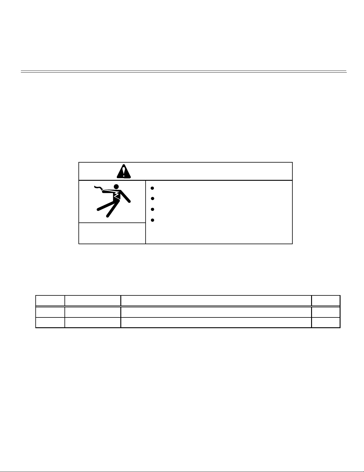
WARNING
Disconnect input power before servicing.
Do not operate with covers removed.
Do not touch electrically live parts.
Only qualified persons should install, use
ELECTRIC SHOCK
CAN KILL
Parts List Required for Installation on Power Wave S700:
Item Part Number Description Qty
1 L17422 Communication Panel Assembly 1
2 S18250-1107 Plug & Lead Assembly (4-pin plug / 4-pin plug) 1
or service this equipment.
1

Power Wave S700 Communication Kit Installation Instructions
Recommended Tools:
• 5/16” nut driver or other suitable tools
CAUTION : PC BOARD CAN BE DAMAGED BY STATIC ELECTRICITY
Bef
ore making any connections to a PC board, remove your body’s static charge by touching unpainted
grounded frame of equipment.
INSTALLATION:
1. Turn off input power to the Power Wave at the disconnect switch or fuse box before working
on the Power Wave.
2. Remove the weld cables from the output studs, and disconnect all control cables including the
Ethernet connection from the Power Wave.
3. Remove the UI cover plate by removing the seven screws fastening the cover plate to the
power source using a 5/16
hardware removed for installing the Power Wave S700 Communication Kit.
4. Obtain Item 2 Plug & Lead Assembly (S18250-1107, 4 pin plug / 4 pin plug).
Connect the Plug & Lead Assembly to J31 (4 pin plug) located in wiring harness of Power
Wave S700 (Figure 2).
5. Obtain Item 1 Communication Panel Assembly provided with the kit. Route the 4-pin
connector P30 of Item 2 Plug & Lead Assembly thru the case front, and to J30 of Item 1
Communication Panel Assembly (Figure 3).
6. Install the Communication Panel Assembly to the Case Front using the hardware removed
from cover plate in Step 3, using a 5/16” nut driver or other suitable tool (Figure 4).
7. Replace the weld cables from the output studs, and reconnect all control cables including the
Ethernet connection from the Power Wave.
8. The WiFi and Bluetooth are disabled as shipped from the factory.
9. After installing the K4352-2 Power Wave S700 Communication Kit, the Power Wave
firmware may need to be updated. Visit www.powerwavesoftware.com for firmware
updates and the Power Wave Utilities. Included with Power Wave Utilities are the
Power Wave Manager PC tool for setting up the wireless or Bluetooth connection, and
the Help Me Connect guide for setup instructions.
”
nut driver or other suitable tool (Figure 1). Retain the mounting
2
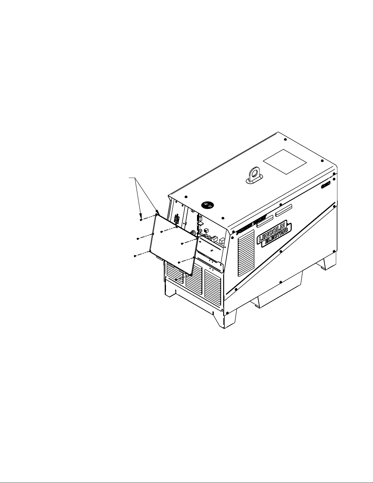
REMOVE COVER PLATE AND
10-24 X .38 SCREWS, (QTY 7)
FIGURE 1
3
 Loading...