

Lincoln Electric POWER WAVE S500 Service Manual
POWER WAVE
For use with machines having Code Numbers:
®
S500
11813
SERVICE MANUAL
View Safety Info View Safety Info View Safety Info View Safety Info
Return to Master TOC Return to Master TOC Return to Master TOC Return to Master TOC
SVM239-A | Issue D ate 13-Oct
© Lincoln Global, Inc. All Rights Reserved.
Need Help? Call 1.888.935.3877
to talk to a Service Representative
Hours of Operation:
8:00 AM to 6:00 PM (ET) Mon. thru Fri.
After hours?
Use “Ask the Experts” at lincolnelectric.com
A Lincoln Service Representative will contact you
no later than the following business day.
For Service outside the USA:
Email: globalservice@lincolnelectric.com
i i
SAFETY
WARNING
CALIFORNIA PROPOSITION 65 WARNINGS
Diesel engine exhaust and some of its constituents
are known to the State of California to cause cancer, birth defects and other reproductive harm.
The Above For Diesel Engines
ARC WELDING can be hazardous. PROTECT YOURSELF AND OTHERS FROM POSSIBLE SERIOUS INJURY OR DEATH.
KEEP CHILDREN AWAY. PACEMAKER WEARERS SHOULD CONSULT WITH THEIR DOCTOR BEFORE OPERATING.
Read and understand the following safety highlights. For additional safety information, it is strongly recommended that you
purchase a copy of “Safety in Welding & Cutting - ANSI Standard Z49.1” from the American Welding Society, P.O. Box 351040,
Miami, Florida 33135 or CSA Standard W117.2-1974. A Free copy of “Arc Welding Safety” booklet E205 is available from the
Lincoln Electric Company, 22801 St. Clair Avenue, Cleveland, Ohio 44117-1199.
BE SURE THAT ALL INSTALLATION, OPERATION, MAINTENANCE AND REPAIR PROCEDURES ARE
PERFORMED ONLY BY QUALIFIED INDIVIDUALS.
The engine exhaust from this product contains
chemicals known to the State of California to cause
cancer, birth defects or other reproductive harm.
The Above For Gasoline Engines
FOR ENGINE
powered equipment.
1.a. Turn the engine off before troubleshooting and maintenance
work unless the maintenance work requires it to be running.
____________________________________________________
____________________________________________________
____________________________________________________
1.d. Keep all equipment safety guards, covers and devices in posi-
tion and in good repair
away from V-belts, gears, fans and all other moving parts
when starting, operating or repairing equipment.
____________________________________________________
1.e. In some cases it may be necessary to remove safety
guards to perform required maintenance. Remove
guards only when necessary and replace them when the
maintenance requiring their removal is complete.
Always use the greatest care when working near moving
parts.
___________________________________________________
1.b.Operate engines in open, well-ventilated
areas or vent the engine exhaust fumes
outdoors.
1.c. Do not add the fuel near an open flame welding arc or when the engine is running. Stop
the engine and allow it to cool before refueling to prevent spilled fuel from vaporizing on
contact with hot engine parts and igniting. Do
not spill fuel when filling tank. If fuel is spilled,
wipe it up and do not start engine until fumes
have been eliminated.
.Keep hands, hair, clothing and tools
1.h. To avoid scalding, do not remove the
radiator pressure cap when the engine is
hot.
ELECTRIC AND
MAGNETIC FIELDS
may be dangerous
2.a. Electric current flowing through any conductor causes
localized Electric and Magnetic Fields (EMF). Welding
current creates EMF fields around welding cables and
welding machines
2.b. EMF fields may interfere with some pacemakers and
welders having a pacemaker should consult their physician
before welding.
2.c. Exposure to EMF fields in welding may have other health
effects which are now not known.
2.d. All welders should use the following procedures in order to
minimize exposure to EMF fields from the welding circuit:
2.d.1.
Route the electrode and work cables together - Secure
them with tape when possible.
2.d.2. Never coil the electrode lead around your body.
1.f. Do not put your hands near the engine fan.
Do not attempt to override the governor or
idler by pushing on the throttle control rods
while the engine is running.
___________________________________________________
1.g. To prevent accidentally starting gasoline engines while
turning the engine or welding generator during maintenance
work, disconnect the spark plug wires, distributor cap or
magneto wire as appropriate.
Return to Master TOC Return to Master TOC Return to Master TOC Return to Master TOC
2.d.3. Do not place your body between the electrode and
work cables. If the electrode cable is on your right
side, the work cable should also be on your right side.
2.d.4. Connect the work cable to the workpiece as close as
possible to the area being welded.
2.d.5. Do not work next to welding power source.
POWER WAVE®S500
ii ii
SAFETY
ELECTRIC SHOCK can kill.
3.a. The electrode and work (or ground) circuits
are electrically “hot” when the welder is on.
Do not touch these “hot” parts with your bare
skin or wet clothing. Wear dry, hole-free
gloves to insulate hands.
3.b. Insulate yourself from work and ground using dry insulation.
Make certain the insulation is large enough to cover your full
area of physical contact with work and ground.
In addition to the normal safety precautions, if welding
must be performed under electrically hazardous
conditions (in damp locations or while wearing wet
clothing; on metal structures such as floors, gratings or
scaffolds; when in cramped positions such as sitting,
kneeling or lying, if there is a high risk of unavoidable or
accidental contact with the workpiece or ground) use
the following equipment:
• Semiautomatic DC Constant Voltage (Wire) Welder.
• DC Manual (Stick) Welder.
• AC Welder with Reduced Voltage Control.
3.c. In semiautomatic or automatic wire welding, the electrode,
electrode reel, welding head, nozzle or semiautomatic
welding gun are also electrically “hot”.
3.d. Always be sure the work cable makes a good electrical
connection with the metal being welded. The connection
should be as close as possible to the area being welded.
3.e. Ground the work or metal to be welded to a good electrical
(earth) ground.
3.f.
Maintain the electrode holder, work clamp, welding cable and
welding machine in good, safe operating condition. Replace
damaged insulation.
3.g. Never dip the electrode in water for cooling.
3.h. Never simultaneously touch electrically “hot” parts of
electrode holders connected to two welders because voltage
between the two can be the total of the open circuit voltage
of both welders.
3.i. When working above floor level, use a safety belt to protect
yourself from a fall should you get a shock.
3.j. Also see Items 6.c. and 8.
ARC RAYS can burn.
4.a. Use a shield with the proper filter and cover
plates to protect your eyes from sparks and
the rays of the arc when welding or observing
open arc welding. Headshield and filter lens
should conform to ANSI Z87. I standards.
4.b. Use suitable clothing made from durable flame-resistant
material to protect your skin and that of your helpers from
the arc rays.
4.c. Protect other nearby personnel with suitable, non-flammable
screening and/or warn them not to watch the arc nor expose
themselves to the arc rays or to hot spatter or metal.
FUMES AND GASES
can be dangerous.
5.a. Welding may produce fumes and gases
hazardous to health. Avoid breathing these
fumes and gases.When welding, keep
your head out of the fume. Use enough
ventilation and/or exhaust at the arc to keep
fumes and gases away from the breathing zone. When
welding with electrodes which require special
ventilation such as stainless or hard facing (see
instructions on container or MSDS) or on lead or
cadmium plated steel and other metals or coatings
which produce highly toxic fumes, keep exposure as
low as possible and within applicable OSHA PEL and
ACGIH TLV limits using local exhaust or mechanical ventilation. In confined spaces or in some circumstances,
outdoors, a respirator may be required. Additional precautions are also required when welding on galvanized
steel.
5.b. The operation of welding fume control equipment is affected
by various factors including proper use and positioning of the
equipment, maintenance of the equipment and the specific
welding procedure and application involved. Worker exposure level should be checked upon installation and periodically thereafter to be certain it is within applicable OSHA PEL
and ACGIH TLV limits.
5.c.
Do not weld in locations near chlorinated hydrocarbon
coming from degreasing, cleaning or spraying operations.
The heat and rays of the arc can react with solvent vapors
form phosgene, a highly toxic gas and other irritating products.
vapors
to
Return to Master TOC Return to Master TOC Return to Master TOC Return to Master TOC
5.d. Shielding gases used for arc welding can displace air and
cause injury or death. Always use enough ventilation,
especially in confined areas, to insure breathing air is safe.
5.e. Read and understand the manufacturerʼs instructions for this
equipment and the consumables to be used, including the
material safety data sheet (MSDS) and follow your employerʼs safety practices. MSDS forms are available from your
welding distributor or from the manufacturer.
5.f. Also see item 1.b.
POWER WAVE®S500
iii iii
SAFETY
WELDING and CUTTING
SPARKS can cause fire or
explosion.
6.a.
this is not possible, cover them to prevent the welding sparks
from starting a fire. Remember that welding sparks and hot
materials from welding can easily go through small cracks
and openings to adjacent areas. Avoid welding near hydraulic
lines. Have a fire extinguisher readily available.
6.b. Where compressed gases are to be used at the job site,
special precautions should be used to prevent hazardous
situations. Refer to “Safety in Welding and Cutting” (ANSI
Standard Z49.1) and the operating information for the
equipment being used.
6.c. When not welding, make certain no part of the electrode
circuit is touching the work or ground. Accidental contact can
cause overheating and create a fire hazard.
6.d. Do not heat, cut or weld tanks, drums or containers until the
proper steps have been taken to insure that such procedures
will not cause flammable or toxic vapors from substances
inside. They can cause an explosion even
been “cleaned”. For information, purchase “Recommended
Safe Practices for the
Containers and Piping That Have Held Hazardous
Substances”, AWS F4.1 from the American Welding Society
(see address above).
6.e. Vent hollow castings or containers before heating, cutting or
welding. They may explode.
Sparks and spatter are thrown from the welding arc. Wear oil
6.f.
free protective garments such as leather gloves, heavy shirt,
cuffless trousers, high shoes and a cap over your hair. Wear
ear plugs when welding out of position or in confined places.
Always wear safety glasses with side shields when in a
welding area.
6.g. Connect the work cable to the work as close to the welding
area as practical. Work cables connected to the building
framework or other locations away from the welding area
increase the possibility of the welding current passing through
lifting chains, crane cables or other alternate circuits. This can
create fire hazards or overheat lifting chains or cables until
they fail.
6.h. Also see item 1.c.
Remove fire hazards from the welding area.
though
they have
Preparation
for Welding and Cutting of
CYLINDER may explode
if damaged.
7.a. Use only compressed gas cylinders
If
pressure used. All hoses, fittings, etc. should be suitable for
the application and maintained in good condition.
7.b. Always keep cylinders in an upright position securely
chained to an undercarriage or fixed support.
7.c. Cylinders should be located:
• Away from areas where they may be struck or subjected to
physical damage.
• A safe distance from arc welding or cutting operations and
any other source of heat, sparks or flame.
7.d. Never allow the electrode, electrode holder or any other
electrically “hot” parts to touch a cylinder.
7.e. Keep your head and face away from the cylinder valve outlet
when opening the cylinder valve.
7.f. Valve protection caps should always be in place and hand
tight except when the cylinder is in use or connected for
use.
7.g. Read and follow the instructions on compressed gas
cylinders, associated equipment and CGA publication P-l,
“Precautions for Safe Handling of Compressed Gases in
Cylinders,” available from the Compressed Gas Association
1235 Jefferson Davis Highway, Arlington, VA 22202.
containing the correct shielding gas for the
process used and properly operating
regulators designed for the gas and
FOR ELECTRICALLY
powered equipment.
8.a. Turn off input power using the disconnect
switch at the fuse box before working on
the equipment.
8.b. Install equipment in accordance with the U.S. National
Electrical Code, all local codes and the manufacturerʼs
recommendations.
8.c. Ground the equipment in accordance with the U.S. National
Electrical Code and the manufacturerʼs recommendations.
6.I. Read and follow NFPA 51B “ Standard for Fire Prevention
During Welding, Cutting and Other Hot Work”, available from
NFPA, 1 Batterymarch Park,PO box 9101, Quincy, Ma
022690-9101.
6.j. Do not use a welding power source for pipe thawing.
Refer to http://www.lincolnelectric.com/safety for additional safety information.
Return to Master TOC Return to Master TOC Return to Master TOC Return to Master TOC
POWER WAVE®S500

iv iv
SAFETY
PRÉCAUTIONS DE SÛRETÉ
Pour votre propre protection lire et observer toutes les instructions
et les précautions de sûreté specifiques qui parraissent dans ce
manuel aussi bien que les précautions de sûreté générales suivantes:
Sûreté Pour Soudage A LʼArc
1. Protegez-vous contre la secousse électrique:
a. Les circuits à lʼélectrode et à la piéce sont sous tension
quand la machine à souder est en marche. Eviter toujours
tout contact entre les parties sous tension et la peau nue
ou les vétements mouillés. Porter des gants secs et sans
trous pour isoler les mains.
b. Faire trés attention de bien sʼisoler de la masse quand on
soude dans des endroits humides, ou sur un plancher metallique ou des grilles metalliques, principalement dans
les positions assis ou couché pour lesquelles une grande
partie du corps peut être en contact avec la masse.
c. Maintenir le porte-électrode, la pince de masse, le câble de
soudage et la machine à souder en bon et sûr état defonctionnement.
d. Ne jamais plonger le porte-électrode dans lʼeau pour le
refroidir.
e. Ne jamais toucher simultanément les parties sous tension
des porte-électrodes connectés à deux machines à souder
parce que la tension entre les deux pinces peut être le total
de la tension à vide des deux machines.
f. Si on utilise la machine à souder comme une source de
courant pour soudage semi-automatique, ces precautions
pour le porte-électrode sʼapplicuent aussi au pistolet de
soudage.
2. Dans le cas de travail au dessus du niveau du sol, se protéger
contre les chutes dans le cas ou on recoit un choc. Ne jamais
enrouler le câble-électrode autour de nʼimporte quelle partie du
corps.
3. Un coup dʼarc peut être plus sévère quʼun coup de soliel, donc:
6. Eloigner les matériaux inflammables ou les recouvrir afin de
prévenir tout risque dʼincendie dû aux étincelles.
7. Quand on ne soude pas, poser la pince à une endroit isolé de
la masse. Un court-circuit accidental peut provoquer un
échauffement et un risque dʼincendie.
8. Sʼassurer que la masse est connectée le plus prés possible de
la zone de travail quʼil est pratique de le faire. Si on place la
masse sur la charpente de la construction ou dʼautres endroits
éloignés de la zone de travail, on augmente le risque de voir
passer le courant de soudage par les chaines de levage,
câbles de grue, ou autres circuits. Cela peut provoquer des
risques dʼincendie ou dʼechauffement des chaines et des
câbles jusquʼà ce quʼils se rompent.
9. Assurer une ventilation suffisante dans la zone de soudage.
Ceci est particuliérement important pour le soudage de tôles
galvanisées plombées, ou cadmiées ou tout autre métal qui
produit des fumeés toxiques.
10. Ne pas souder en présence de vapeurs de chlore provenant
dʼopérations de dégraissage, nettoyage ou pistolage. La
chaleur ou les rayons de lʼarc peuvent réagir avec les vapeurs
du solvant pour produire du phosgéne (gas fortement toxique)
ou autres produits irritants.
11. Pour obtenir de plus amples renseignements sur la sûreté, voir
le code “Code for safety in welding and cutting” CSA Standard
W 117.2-1974.
PRÉCAUTIONS DE SÛRETÉ POUR
LES MACHINES À SOUDER À
TRANSFORMATEUR ET À
REDRESSEUR
a. Utiliser un bon masque avec un verre filtrant approprié ainsi
quʼun verre blanc afin de se protéger les yeux du rayonnement de lʼarc et des projections quand on soude ou
quand on regarde lʼarc.
b. Porter des vêtements convenables afin de protéger la peau
de soudeur et des aides contre le rayonnement de lʻarc.
c. Protéger lʼautre personnel travaillant à proximité au
soudage à lʼaide dʼécrans appropriés et non-inflammables.
4. Des gouttes de laitier en fusion sont émises de lʼarc de
soudage. Se protéger avec des vêtements de protection libres
de lʼhuile, tels que les gants en cuir, chemise épaisse, pantalons sans revers, et chaussures montantes.
5. Toujours porter des lunettes de sécurité dans la zone de
soudage. Utiliser des lunettes avec écrans lateraux dans les
zones où lʼon pique le laitier.
Return to Master TOC Return to Master TOC Return to Master TOC Return to Master TOC
1. Relier à la terre le chassis du poste conformement au code de
lʼélectricité et aux recommendations du fabricant. Le dispositif
de montage ou la piece à souder doit être branché à une
bonne mise à la terre.
2. Autant que possible, Iʼinstallation et lʼentretien du poste seront
effectués par un électricien qualifié.
3. Avant de faires des travaux à lʼinterieur de poste, la debrancher à lʼinterrupteur à la boite de fusibles.
4. Garder tous les couvercles et dispositifs de sûreté à leur place.
POWER WAVE®S500

v v
SAFETY
Electromagnetic Compatibility (EMC)
Conformance
Products displaying the CE mark are in conformity with European Community Council Directive of 15 Dec
2004 on the approximation of the laws of the Member States relating to electromagnetic compatibility,
2004/108/EC. It was manufactured in conformity with a national standard that implements a harmonized
standard: EN 60974-10 Electromagnetic Compatibility (EMC) Product Standard for Arc Welding Equipment.
It is for use with other Lincoln Electric equipment. It is designed for industrial and professional use.
Introduction
All electrical equipment generates small amounts of electromagnetic emission. Electrical emission may be
transmitted through power lines or radiated through space, similar to a radio transmitter. When emissions
are received by other equipment, electrical interference may result. Electrical emissions may affect many
kinds of electrical equipment; other nearby welding equipment, radio and TV reception, numerical controlled
machines, telephone systems, computers, etc. Be aware that interference may result and extra precautions
may be required when a welding power source is used in a domestic establishment.
Installation and Use
The user is responsible for installing and using the welding equipment according to the manufacturerʼs
instructions. If electromagnetic disturbances are detected then it shall be the responsibility of the user of the
welding equipment to resolve the situation with the technical assistance of the manufacturer. In some cases
this remedial action may be as simple as earthing (grounding) the welding circuit, see Note. In other cases
it could involve construction of an electromagnetic screen enclosing the power source and the work complete with associated input filters. In all cases electromagnetic disturbances must be reduced to the point
where they are no longer troublesome.
Note: The welding circuit may or may not be earthed for safety reasons according to national
codes. Changing the earthing arrangements should only be authorized by a person who is
competent to access whether the changes will increase the risk of injury, e.g., by allowing
parallel welding current return paths which may damage the earth circuits of other equipment.
Assessment of Area
Before installing welding equipment the user shall make an assessment of potential electromagnetic problems in the surrounding area. The following shall be taken into account:
a) other supply cables, control cables, signaling and telephone cables; above, below and adjacent to the
welding equipment;
b) radio and television transmitters and receivers;
c) computer and other control equipment;
d) safety critical equipment, e.g., guarding of industrial equipment;
e) the health of the people around, e.g., the use of pacemakers and hearing aids;
f) equipment used for calibration or measurement
g) the immunity of other equipment in the environment. The user shall ensure that other equipment being
used in the environment is compatible. This may require additional protection measures;
h) the time of day that welding or other activities are to be carried out.
Return to Master TOC Return to Master TOC Return to Master TOC Return to Master TOC
POWER WAVE®S500

vi vi
SAFETY
Electromagnetic Compatibility (EMC)
The size of the surrounding area to be considered will depend on the structure of the building and other
activities that are taking place. The surrounding area may extend beyond the boundaries of the premises.
Methods of Reducing Emissions
Mains Supply
Welding equipment should be connected to the mains supply according to the manufacturerʼs recommendations. If interference occurs, it may be necessary to take additional precautions such as filtering of the
mains supply. Consideration should be given to shielding the supply cable of permanently installed welding
equipment, in metallic conduit or equivalent. Shielding should be electrically continuous throughout its
length. The shielding should be connected to the welding power source so that good electrical contact is
maintained between the conduit and the welding power source enclosure.
Maintenance of the Welding Equipment
The welding equipment should be routinely maintained according to the manufacturerʼs recommendations.
All access and service doors and covers should be closed and properly fastened when the welding equipment is in operation. The welding equipment should not be modified in any way except for those changes
and adjustments covered in the manufacturers instructions. In particular, the spark gaps of arc striking and
stabilizing devices should be adjusted and maintained according to the manufacturerʼs recommendations.
Welding Cables
The welding cables should be kept as short as possible and should be positioned close together, running at
or close to floor level.
Equipotential Bonding
Bonding of all metallic components in the welding installation and adjacent to it should be considered.
However, metallic components bonded to the work piece will increase the risk that the operator could
receive a shock by touching these metallic components and the electrode at the same time. The operator
should be insulated from all such bonded metallic components.
Earthing of the Workpiece
Where the workpiece is not bonded to earth for electrical safety, not connected to earth because of its size
and position, e.g., ships hull or building steelwork, a connection bonding the workpiece to earth may reduce
emissions in some, but not all instances. Care should be taken to prevent the earthing of the workpiece
increasing the risk of injury to users or damage to other electrical equipment. Where necessary, the connection of the workpiece to earth should be made by a direct connection to the workpiece, but in some
countries where direct connection is not permitted, the bonding should be achieved by suitable capacitance, selected according to national regulations.
Screening and Shielding
Selective screening and shielding of other cables and equipment in the surrounding area may alleviate
problems of interference. Screening of the entire welding installation may be considered for special applica-
1
tions.
_________________________
1
Portions of the preceding text are contained in EN 60974-10: “Electromagnetic Compatibility (EMC)
product standard for arc welding equipment.”
Return to Master TOC Return to Master TOC Return to Master TOC Return to Master TOC
POWER WAVE®S500

I I
- MASTER TABLE OF CONTENTS FOR ALL SECTIONS -
RETURN TO MAIN INDEX
Page
Safety . . . . . . . . . . . . . . . . . . . . . . . . . . . . . . . . . . . . . . . . . . . . . . . . . . . . . . . . . . . . . . . . . . . . . . . . . . .i-vi
Installation . . . . . . . . . . . . . . . . . . . . . . . . . . . . . . . . . . . . . . . . . . . . . . . . . . . . . . . . . . . . . . . . . .Section A
Operation . . . . . . . . . . . . . . . . . . . . . . . . . . . . . . . . . . . . . . . . . . . . . . . . . . . . . . . . . . . . . . . . . .Section B
Accessories . . . . . . . . . . . . . . . . . . . . . . . . . . . . . . . . . . . . . . . . . . . . . . . . . . . . . . . . . . . . . . . .Section C
Maintenance . . . . . . . . . . . . . . . . . . . . . . . . . . . . . . . . . . . . . . . . . . . . . . . . . . . . . . . . . . . . . . . .Section D
Theory of Operation . . . . . . . . . . . . . . . . . . . . . . . . . . . . . . . . . . . . . . . . . . . . . . . . . . . . . . . . . .Section E
Troubleshooting and Repair . . . . . . . . . . . . . . . . . . . . . . . . . . . . . . . . . . . . . . . . . . . . . . . . . . .Section F
Electrical Diagrams . . . . . . . . . . . . . . . . . . . . . . . . . . . . . . . . . . . . . . . . . . . . . . . . . . . . . . . . . .Section G
Parts Manual . . . . . . . . . . . . . . . . . . . . . . . . . . . . . . . . . . . . . . . . . . . . . . . . . . . . . . . . . . . . . . . . . . .P-690
POWER WAVE®S500

A-1 A-1
Installation . . . . . . . . . . . . . . . . . . . . . . . . . . . . . . . . . . . . . . . . . . . . . . . . . . . . . . . . . . . . . . . . . . . . . . . . . . . . .A-1
Technical Specifications . . . . . . . . . . . . . . . . . . . . . . . . . . . . . . . . . . . . . . . . . . . . . . . . . . . . . . . . . . . . .A-2/A-3
Safety Precautions . . . . . . . . . . . . . . . . . . . . . . . . . . . . . . . . . . . . . . . . . . . . . . . . . . . . . . . . . . . . . . . . . . . .A-4
Select Suitable Location . . . . . . . . . . . . . . . . . . . . . . . . . . . . . . . . . . . . . . . . . . . . . . . . . . . . . . . . . . . . . . . .A-4
Lifting . . . . . . . . . . . . . . . . . . . . . . . . . . . . . . . . . . . . . . . . . . . . . . . . . . . . . . . . . . . . . . . . . . . . . . . . . . . . . .A-4
Stacking . . . . . . . . . . . . . . . . . . . . . . . . . . . . . . . . . . . . . . . . . . . . . . . . . . . . . . . . . . . . . . . . . . . . . . . . . . . .A-4
Tilting . . . . . . . . . . . . . . . . . . . . . . . . . . . . . . . . . . . . . . . . . . . . . . . . . . . . . . . . . . . . . . . . . . . . . . . . . . . . . .A-4
Input And Ground Connections . . . . . . . . . . . . . . . . . . . . . . . . . . . . . . . . . . . . . . . . . . . . . . . . . . . . . . . . . .A-4
Machine Grounding . . . . . . . . . . . . . . . . . . . . . . . . . . . . . . . . . . . . . . . . . . . . . . . . . . . . . . . . . . . . . . . . . . .A-4
TABLE OF CONTENTS - INSTALLATION SECTION
High Frequency Protection . . . . . . . . . . . . . . . . . . . . . . . . . . . . . . . . . . . . . . . . . . . . . . . . . . . . . . . . . . . . . .A-4
Input Connection . . . . . . . . . . . . . . . . . . . . . . . . . . . . . . . . . . . . . . . . . . . . . . . . . . . . . . . . . . . . . . . . . . . . .A-5
Input Fuse And Supply Wire Connections . . . . . . . . . . . . . . . . . . . . . . . . . . . . . . . . . . . . . . . . . . . . . . . . . .A-5
Input Voltage Selection . . . . . . . . . . . . . . . . . . . . . . . . . . . . . . . . . . . . . . . . . . . . . . . . . . . . . . . . . . . . . . . .A-5
Connection Diagrams . . . . . . . . . . . . . . . . . . . . . . . . . . . . . . . . . . . . . . . . . . . . . . . . . . . . . . . . . . . . . .A-6/A-8
Recommended Work Cable Sizes For Arc Welding . . . . . . . . . . . . . . . . . . . . . . . . . . . . . . . . . . . . . . . . . .A-9
General Guidelines . . . . . . . . . . . . . . . . . . . . . . . . . . . . . . . . . . . . . . . . . . . . . . . . . . . . . . . . . . . . . . . . . . . .A-9
Cable Inductance And Its Effects On Welding . . . . . . . . . . . . . . . . . . . . . . . . . . . . . . . . . . . . . . . . . . . . . .A-10
Remote Sense Lead Specifications . . . . . . . . . . . . . . . . . . . . . . . . . . . . . . . . . . . . . . . . . . . . . . . . . .A-10/A-11
Voltage Sensing Considerations For Multiple Arc Systems . . . . . . . . . . . . . . . . . . . . . . . . . . . . . . .A-12/A-13
Control Cable Connections . . . . . . . . . . . . . . . . . . . . . . . . . . . . . . . . . . . . . . . . . . . . . . . . . . . . . . . . . . . .A-14
Return to Master TOC Return to Master TOC Return to Master TOC Return to Master TOC
POWER WAVE®S500
A-2 A-2
INSTALLATION
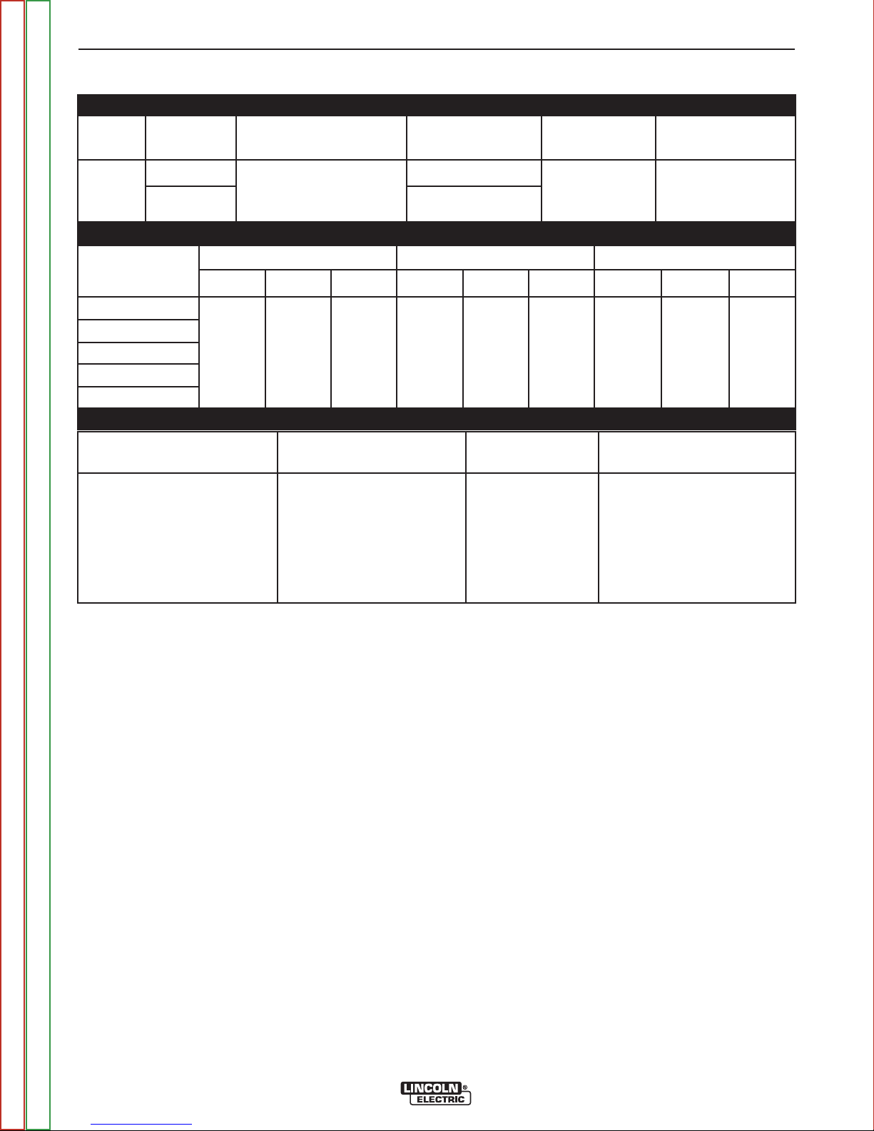
TECHNICAL SPECIFICATIONS - POWER WAVE®S500
POWER SOURCE-INPUT VOLTAGE AND CURRENT
MODEL DUTY
CYCLE
INPUT VOLTAGE
± 10%
INPUT AMPERES IDLE POWER POWER FACTOR
@ RATED OUTPUT
K2904-1 40% rating 208/230/400*460/575
100% rating 60/54/30/27/21
INPUT
VOLTAGE/PHASE/
FREQUENCY
200-208/3/50/60
230/3/50/60
(includes 380V to 413V)
40% 60% 100% 40% 60% 100% 40% 60% 100%
550 Amps
41.5 Volts
50/60 Hz
GMAW SMAW GTAW-DC
500 Amps
39 Volts
450 Amps
36.5 Volts
380-415/3/50/60
460/3/50/60
575/3/50/60
RECOMMENDED INPUT WIRE AND FUSE SIZES
INPUT VOLTAGE/PHASE/
FREQUENCY
200-208/3/50/60
230/3/50/60
380-415/3/50/60
460/3/50/60
MAXIMUM INPUT AMPERE
RATING AND DUTY CYCLE
80A, 40%
73A, 40%
41A, 40%
37A, 40%
80/73/41/37/29 500 Watts Max.
RATED OUTPUT
550 Amps
42 Volts
500 Amps
40 Volts
CORD SIZE 3AWG
SIZES (mm2)
450 Amps
38 Volts
2 (35)
2 (35)
6 (13)
6 (13)
(fan on)
550 Amps
32 Volts
500 Amps
30 Volts
1
TIME DELAY FUSE OR
BREAKER 2AMPERAGE
100
.95
450 Amps
28 Volts
90
60
45
575/3/50/60
1. Based on U.S. National electrical Code.
2. Also called "inverse time" or "thermal / magnetic" circuit breakers; circuit breakers that have a delay in tripping action that decreases as
the magnitude of the current increases.
3. Type SO cord or similar in 30° C ambient.
29A, 40%
8 (10)
35
Return to Master TOC Return to Master TOC Return to Master TOC Return to Master TOC
Return to Section TOC Return to Section TOC Return to Section TOC Return to Section TOC
POWER WAVE®S500
A-3 A-3
INSTALLATION
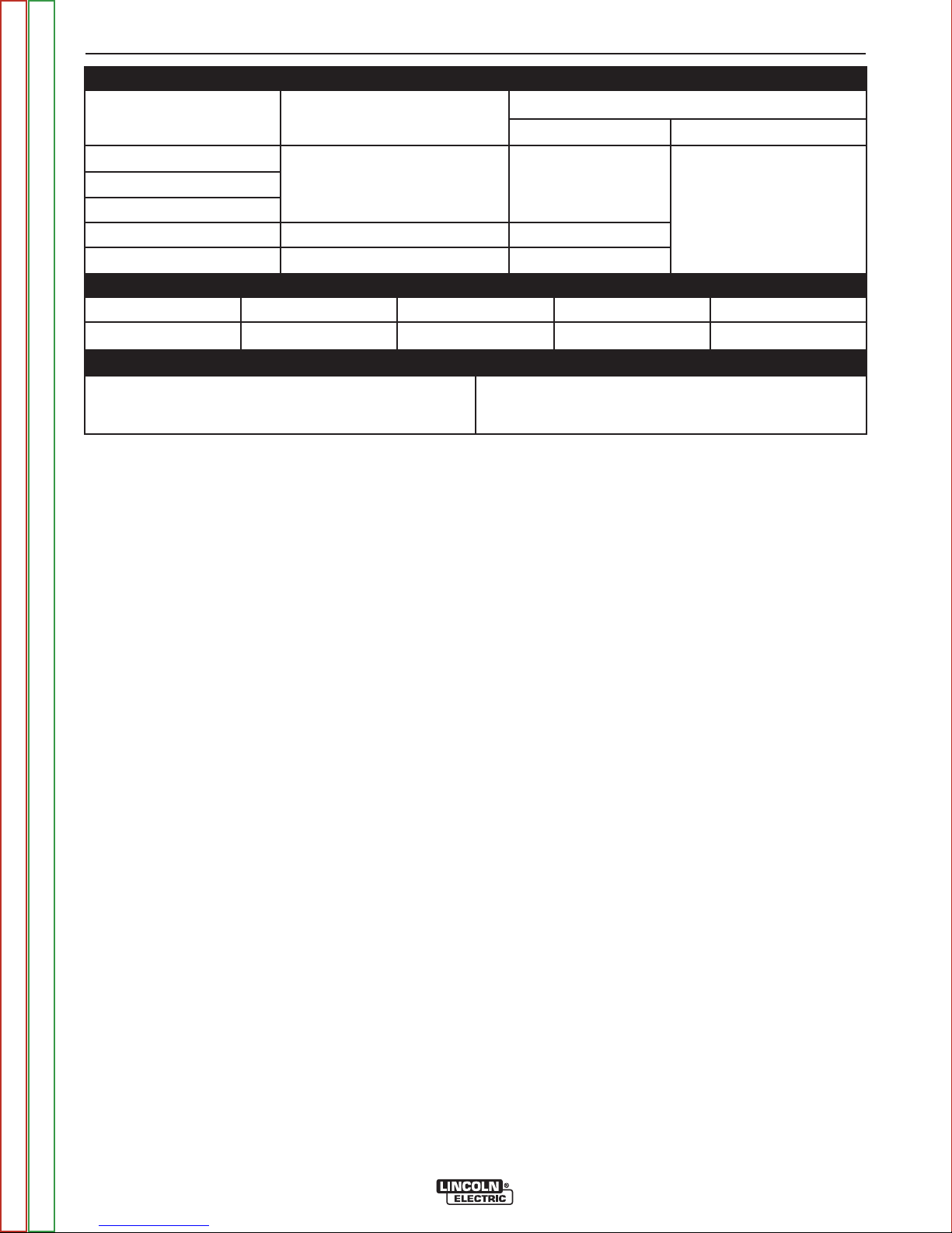
WELDING PROCESS
PROCESS OUTPUT RANGE (AMPERES) OCV (Uo)
Mean Peak
GMAW 40-550A 60V 100V
GMAW-Pulse
FCAW
GTAW-DC 5-550A 24V
SMAW 15-550A 60V
PHYSICAL DIMENSIONS
MODEL HEIGHT WIDTH DEPTH WEIGHT
K2904-1 22.45 in. (570 mm) 14.00 in. (356 mm) 24.08 in. (630 mm) 150 lbs (68kg)*
TEMPERATURE RANGES
OPERATING TEMPERATURE RANGE
STORAGE TEMPERATURE
Environmentally Hardened: -4º to 104ºF (-20º to 40ºC)
IP23 155º(F) Insulation Class
* Weight does not include input cord.
Thermal tests have been performed at ambient temperature. The duty cycle (duty factor) at 40°C has been determined by
simulation.
Environmentally Hardened: -40º to 185ºF (-40º to 85ºC)
Return to Master TOC Return to Master TOC Return to Master TOC Return to Master TOC
Return to Section TOC Return to Section TOC Return to Section TOC Return to Section TOC
POWER WAVE®S500

A-4 A-4
INSTALLATION
SAFETY PRECAUTIONS
Read this entire installation section before you
start installation.
WARNING
ELECTRIC SHOCK can kill.
• Only qualified personnel should
perform this installation.
• Turn the input power OFF at the disconnect
switch or fuse box before working on this equipment. Turn off the input power to any other equipment connected to the welding system at the disconnect switch or fuse box before working on the
equipment.
• Do not touch electrically hot parts.
• Always connect the Power Wave
lug to a proper safety (Earth) ground.
------------------------------------------------------------------------
®
S500 grounding
SELECT SUITABLE LOCATION
®
The Power Wave
ments. Even so, it is important that simple preventative
measures are followed in
reliable operation.
S500 will operate in harsh environ-
order to assure long
life and
WARNING
FALLING EQUIPMENT can
cause injury.
• Lift only with equipment of adequate lifting capacity.
• Be sure machine is stable when lifting.
• Do not operate machine while suspended when
lifting.
------------------------------------------------------------------------
STACKING
The Power Wave®S500 cannot be stacked.
TILTING
Place the machine directly on a secure, level surface
or on a recommended undercarriage. The machine
may topple over if this procedure is not followed.
INPUT AND GROUND CONNECTIONS
Only a qualified electrician should connect the Power
Wave®S500. Installation should be made in accordance with the appropriate National Electrical Code, all
local codes and the information in this manual.
• The machine must be lo
tion of clean air.
• Dirt and dust that can be drawn into the machine
should be kept to a minimum. The us
the air intake is not recommende
air flow may be restricted. Failure to observe these
precautions can result in excessive operating temperatures and nuisance shutdown.
• Keep machine dry
not place on wet ground or in puddles.
• Do not mount the Power Wave
bustible surfaces. Where there is a combustible surface directly under stationary or fixed electrical equipment, that surface s
at least .060” (1.6mm) thick, which shall extend not
less than 5.90” (150mm) beyond the equipment on all
sides.
cated where there is
e of air filters on
d because normal
. Shelter from rain and
®
S500 over com-
hall be covered with a steel plate
circula-
snow. Do
LIFTING
Both handles should be used when lifting Power
®
Wave
a lifting strap should be connected to both handles. Do
not attempt to lift the Power Wave
sories attached to it.
S500. When using a crane or overhead device
®
S500 with acces-
MACHINE GROUNDING
The frame of the welder must be grounded. A ground
terminal marked with a ground symbol is located next
to the input power connection block.
See your local and national electrical codes for proper
grounding methods.
HIGH FREQUENCY PROTECTION
Locate the Power Wave®S500 away from radio controlled machinery. The normal operation of the Power
®
Wave
controlled equipment, which may result in bodily injury
or damage to the equipment.
S500 may adversely affect the operation of RF
Return to Master TOC Return to Master TOC Return to Master TOC Return to Master TOC
Return to Section TOC Return to Section TOC Return to Section TOC Return to Section TOC
POWER WAVE®S500
A-5 A-5
INSTALLATION
WARNING
Only a qualified electrician should connect the
input leads to the Power Wave
should be made in accordance with all local and
national electrical codes and the connection diagrams. Failure to do so may result in bodily injury
or death.
------------------------------------------------------------------------
®
S500. Connections
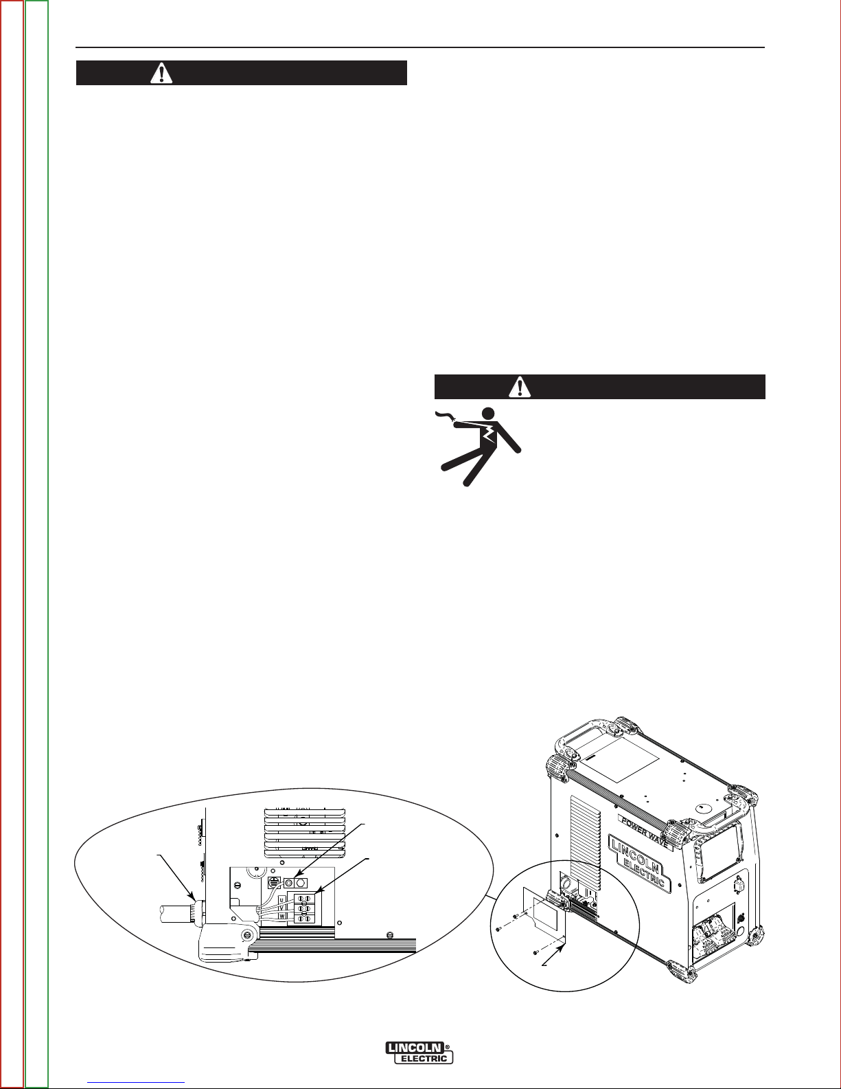
INPUT CONNECTION
(See Figure A.1)
Use a three-phrase supply line. A 1.40 inch diameter
access hole with strain relief is located on the case
back. Route input power cable through this hole and
connect L1, L2, L3 and ground per connection diagrams and National Electric Code. To access the input
power connection block, remove three screws holding
the access door to the side of the machine.
ALWAYS CONNECT THE POWER WAVE GROUNDING LUG (LOCATED AS SHOWN IN FIGURE A.1) TO
A PROPER SAFETY (EARTH) GROUND.
INPUT FUSE AND SUPPLY WIRE
CONSIDERATIONS
See Technical Specifications for recommended fuse,
wire sizes and type of the copper wires. Fuse the input
circuit with the recommended super lag fuse or delay
type breakers (also called "inverse time" or "thermal/magnetic" circuit breakers). Choose input and
grounding wire size according to local or national electrical codes. Using input wire sizes, fuses or circuit
breakers smaller than recommended may result in
"nuisance" shut-offs from welder inrush currents, even
if the machine is not being used at high currents.
INPUT VOLTAGE SELECTION
The Power Wave®S500 automatically adjusts to work
with different input voltages. No reconnect switch settings are required.
WARNING
The Power Wave®S500 ON/OFF
switch is not intended as a service
disconnect for this equipment. Only
a qualified electrician should connect the input leads to the Power
®
Wave
made in accordance with all local
and national electrical codes and
the connection diagram located on
the inside of the reconnect access
door of the machine. Failure to do
so may result in bodily injury or
death.
S500. Connections should be
Return to Section TOC Return to Section TOC Return to Section TOC Return to Section TOC
Return to Master TOC Return to Master TOC Return to Master TOC Return to Master TOC
INPUT CORD STRAIN RELIEF
ROUTE INPUT CORD
THROUGH RELIEF AND
TWIST NUT TO TIGHTEN
------------------------------------------------------------------------
FIGURE A.1
GROUND CONNECTION
CONNECT GROUND LEAD PER LOCAL
AND NATIONAL ELECTRIC CODE
POWER CONNECTION BLOCK
CONNECT EACH PHASE OF A THREE-PHASE
CONDUCTOR HERE
POWER WAVE®S500
INPUT POWER
ACCESS DOOR
A-6 A-6
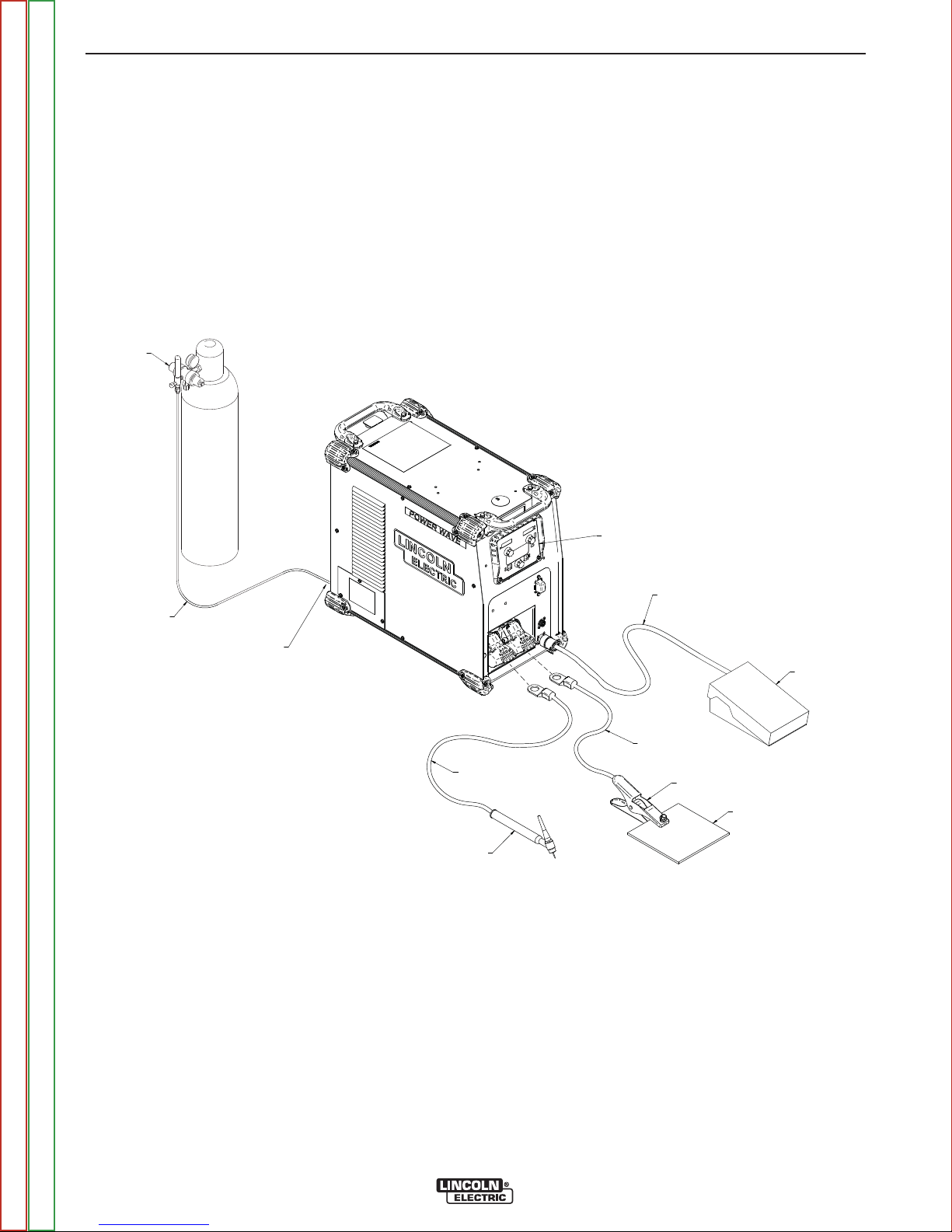
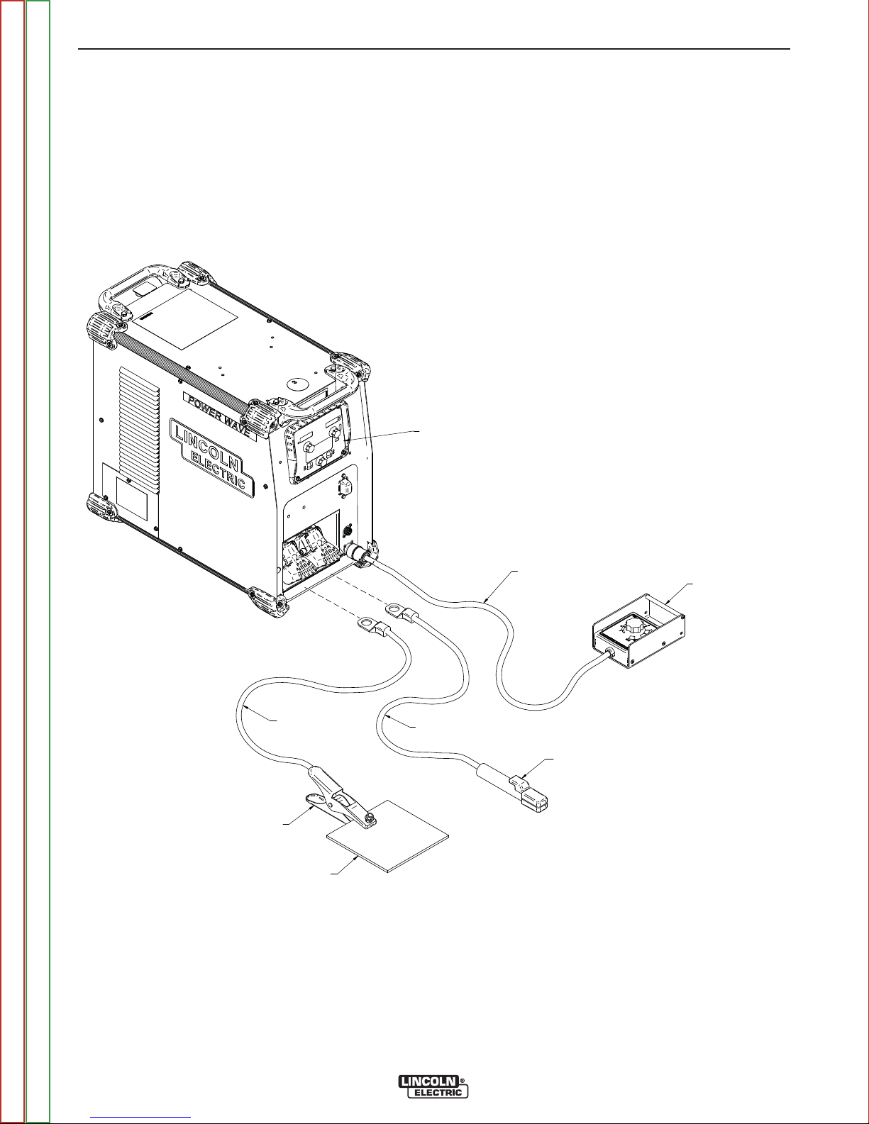
REGULATOR
FLOWMETER
GAS HHOSE
FOOT AAMPTROL
K
870
WORK PPIECE
WORK CCLAMP
TIG TTORCRCH
K2266-1
KIT
(I
NCLUDUDESES WWORK CCLAMP,
AD
APTER, AANDND RREGULATOR)
TO PPOSITIVEVE ((+) SSTUD
TO RREMOTE CCONTROL
REC
EPTACLE
USESER I INTERFACE
CONTROL
PANEL
K
01-2
GAS SSOLENOID KKITIT
(INSIDE
CHINE)
K2
825-1
TO NNEGATIVEVE ((-) SSTUD
INSTALLATION
CONNECTION DIAGRAMS
GTAW (TIG) WELDING
A user interface is required for adjusting the TIG welding settings. S-series user interface (K3001-2) can be
installed into the power source (Figure A.2). Refer to
the connection diagrams based on the user interface
that is being used. Alternate configurations are possible depending on the wire feeder that is being used.
Refer to the wire feederʼs manual for alternative configurations.
FIGURE A.2
TIG WITH S-SERIES USER INTERFACE
MMACH
PA
303001
EP
82
NC
AP
K
87
Return to Master TOC Return to Master TOC Return to Master TOC Return to Master TOC
Return to Section TOC Return to Section TOC Return to Section TOC Return to Section TOC
POWER WAVE®S500
A-7 A-7
INSTALLATION
SMAW (STICK) WELDING
Similar to TIG welding a user interface is required for
adjusting the Stick welding settings. A Power Feed
wire feeder can be used as the user interface or a
K3001-2 (user interface control panel) can be installed
into the power source (Figure A.3). The connection diagram shown is based on the S-Series user interface
(K3001-2). In this diagram the remote control box is
optional.
FIGURE A.3
STICK WITH S-SERIES USER INTERFACE
USER INTERFACE
CONTROL PANEL
K3001-2
WORK CLAMP
TO NEGATIVE (-) STUD
WORK PIECE
TO POSITIVE (+) STUD
TO REMOTE CONTROL
RECEPTACLE
ELECTRODE HOLDER KIT
K2394-1 KIT
(INICLUDES GROUND CLAMP)
REMOTE CONTROL BOX
K857
Return to Master TOC Return to Master TOC Return to Master TOC Return to Master TOC
Return to Section TOC Return to Section TOC Return to Section TOC Return to Section TOC
POWER WAVE®S500
A-8 A-8
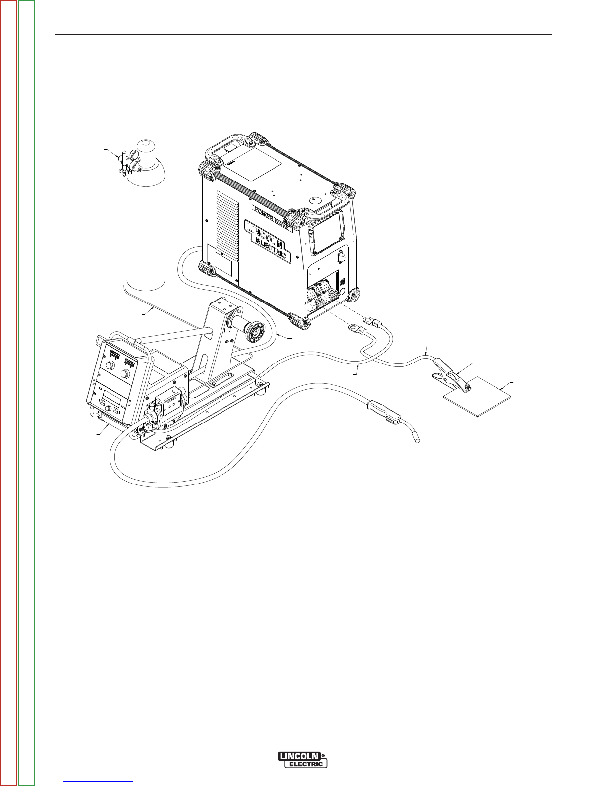
REGULATOR
FLOWMETER
GASAS HHOSE
WORK PPIECE
WORK CCLAMP
TO PPOSITIVEVE ((+) SSTUD
TO NNEGATIVEVE ((-) SSTUD
PF1010-M
WIRE F FEEEEDER
ARCRCLINK CCABLE
K1543-[XX]
INSTALLATION
GMAW (MIG) WELDING
An arclink compatible wire feeder is recommended for
Mig welding. See Figure A.4 for the connection details.
FIGURE A4
MIG PROCESS
Return to Master TOC Return to Master TOC Return to Master TOC Return to Master TOC
Return to Section TOC Return to Section TOC Return to Section TOC Return to Section TOC
POWER WAVE®S500
A-9 A-9
INSTALLATION
RECOMMENDED WORK CABLE
SIZES FOR ARC WELDING
Connect the electrode and work cables between the
appropriate output studs of the Power Wave
the following guidelines:
• Most welding applications run with the electrode
being positive (+). For those applications, connect the
electrode cable between the wire drive feed plate and
the positive (+) output stud on the power source.
Connect a work lead from the negative (-) power
source output stud to the work piece.
• When negative electrode polarity is required, such as
in some Innershield applications, reverse the output
connections at the power source (electrode cable to
the negative (-) stud and work cable to the positive (+)
stud).
®
S500 per
CAUTION
Negative electrode polarity operation WITHOUT
use of a remote work sense lead (21) requires the
Negative Electrode Polarity attribute to be set. See
the Remote Sense Lead Specification section of
this document for further details.
GENERAL GUIDELINES
• Select the appropriate size cables per the “Output
Cable Guidelines” below. Excessive voltage drops
caused by undersized welding cables and poor connections often result in unsatisfactory welding performance. Always use the largest welding cables (electrode and work) that are practical and be sure all connections are clean and tight.
NOTE: Excessive heat in the weld circuit indicates
undersized cables and/or bad connections.
• Route all cables directly to the work and wire
feeder, avoid excessive lengths and do not coil
excess cable. Route the electrode and work cables
in close proximity to one another to minimize the loop
area and therefore the inductance of the weld circuit.
• Always weld in a direction away from the work
(ground) connection.
Table A.1 shows copper cable sizes recommended for
different currents and duty cycles. Lengths stipulated
are the distance from the welder to work and back to
the welder again. Cable sizes are increased for
greater lengths primarily for the purpose of minimizing
cable drop.
------------------------------------------------------------------------
For additional Safety information regarding the electrode and work cable set-up, See the standard Safety
Information located in the front of this Service
Manual.
TABLE A.1 – OUTPUT CABLE GUIDELINES
Amperes
200
250
300
350
400
450
500
Percent Duty
Cycle
100
100
100
100
100
100
60
CABLE SIZES FOR COMBINED LENGTHS OF ELECTRODE AND WORK
CABLES [RUBBER COVERED COPPER - RATED 167°F (75°C)]**
0 to 50 Ft.
2
1
2/0
2/0
3/0
3/0
2/0
50 to 100 Ft.
2
1
2/0
2/0
3/0
3/0
2/0
100 to 150 Ft.
2
1
2/0
3/0
3/0
4/0
3/0
150 to 200 Ft.
1
1
2/0
3/0
3/0
4/0
3/0
200 to 250 Ft.
1/0
1/0
3/0
4/0
4/0
2-3/0
4/0
550
** Tabled values are for operation at ambient temperatures of 104°F (40°C) and below. Applications above
104°F (40°C) may require cables larger than recommended or cables rated higher than 167°F (75°C).
Return to Master TOC Return to Master TOC Return to Master TOC Return to Master TOC
Return to Section TOC Return to Section TOC Return to Section TOC Return to Section TOC
40
2/0
2/0
POWER WAVE®S500
3/0
3/0
4/0
A-10 A-10
INSTALLATION
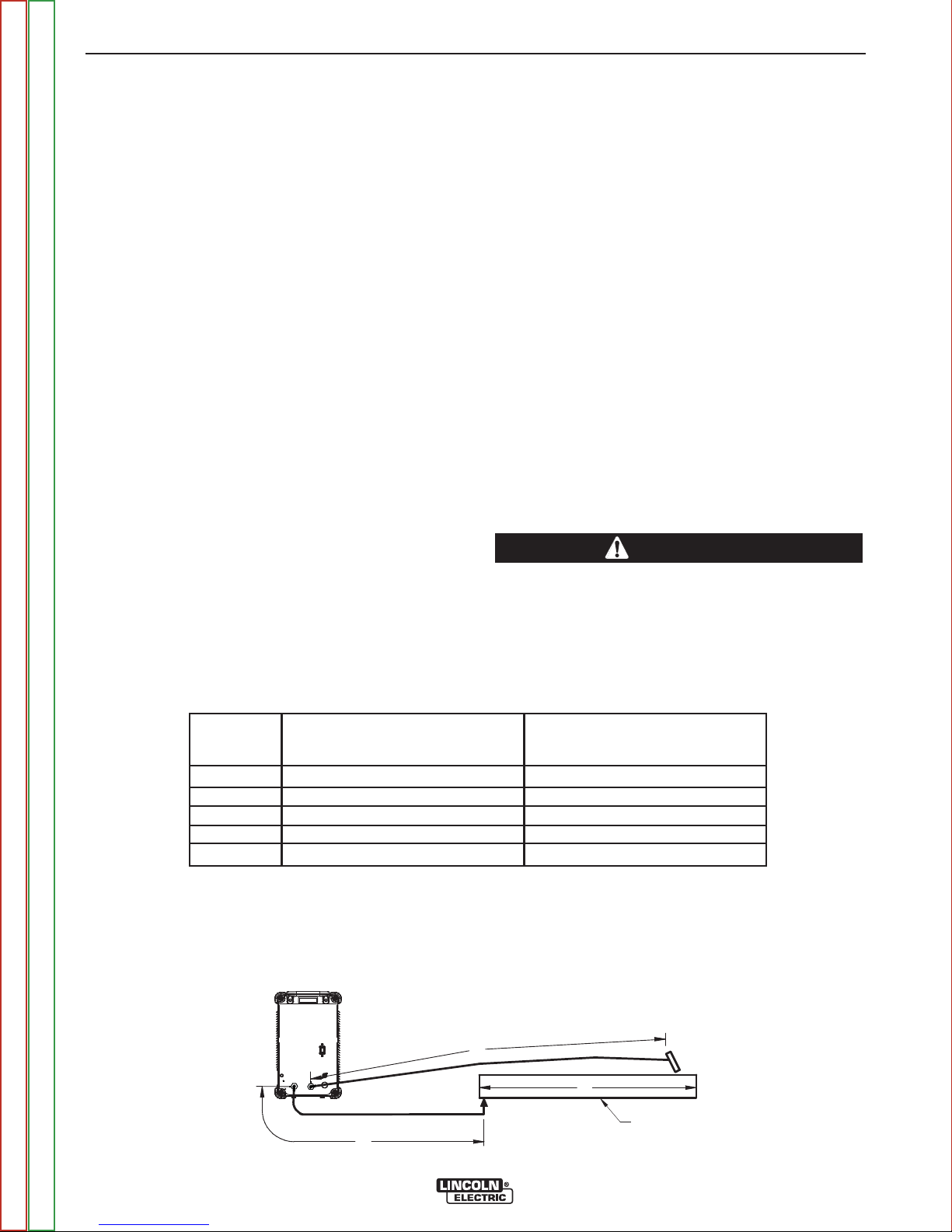
CABLE INDUCTANCE AND ITS
EFFECTS ON WELDING
Excessive cable inductance will cause the welding performance to degrade. There are several factors that
contribute to the overall inductance of the cabling system including cable size and loop area. The loop area
is defined by the separation distance between the electrode and work cables and the overall welding loop
length. The welding loop length is defined as the total
of length of the electrode cable (A) + work cable (B) +
work path (C) (See Figure A.5).
To minimize inductance always use the appropriate
size cables and whenever possible, run the electrode
and work cables in close proximity to one another to
minimize the loop area. Since the most significant factor in cable inductance is the welding loop length, avoid
excessive lengths and do not coil excess cable. For
long work piece lengths, a sliding ground should be
considered to keep the total welding loop length as
short as possible.
REMOTE SENSE LEAD SPECIFICATIONS
VOLTAGE SENSING OVERVIEW
The best arc performance occurs when the Power
Wave®S500 has accurate data about the arc conditions.
Depending upon the process, inductance within the
electrode and work cables can influence the voltage
apparent at the studs of the welder and have a dramatic effect on performance. Remote voltage sense
leads are used to improve the accuracy of the arc voltage information supplied to the control pc board.
Sense Lead Kits (K940-xx) are available for this purpose.
The Power Wave
ly sense when remote sense leads are connected.
With this feature there are no requirements for settingup the machine to use remote sense leads. This feature can be disabled through the Weld Manager Utility
(available at www.powerwavesoftware.com) or
through the set up menu (if a user interface is installed
into the power source).
®
S500 has the ability to automatical-
CAUTION
If the auto sense lead feature is disabled and
remote voltage sensing is enabled but the sense
leads are missing or improperly connected
extremely high welding outputs may occur.
------------------------------------------------------------------------
TABLE A.2
Process
Electrode Voltage Sensing
67 lead
GMAW
GMAW-P
FCAW
GTAW
SMAW
(1)
The electrode voltage sense lead (67) is automatically enabled by the weld process and integral to the 5 pin arclink control cable
(K1543-xx).
(2)
When a work voltage sense lead (21) is connected the power source will automatically switch over to using this feedback (if the auto
sense feature is enable).
(3)
Negative polarity semi-automatic process operation WITHOUT use of a remote work sense lead (21) requires the Negative Electrode
Polarity attribute to be set.
67 lead required
67 lead required
67 lead required
Voltage sense at studs
Voltage sense at studs
(1)
Work Voltage Sensing
21 lead
21 lead optional
21 lead optional
21 lead optional
Voltage sense at studs
Voltage sense at studs
FIGURE A.5
(2)
(3)
(3)
(3)
POWER
WAVE
S500
Return to Master TOC Return to Master TOC Return to Master TOC Return to Master TOC
Return to Section TOC Return to Section TOC Return to Section TOC Return to Section TOC
A
C
WORK
B
POWER WAVE®S500

A-11 A-11
INSTALLATION
GENERAL GUIDELINES FOR VOLTAGE
SENSE LEADS
Sense leads should be attached as close to the weld
as practical and out of the weld current path when possible. In extremely sensitive applications it may be necessary to route cables that contain the sense leads
away from the electrode and work welding cables.
Voltage sense lead requirements are based on the
weld process. See Table A.2.
ELECTRODE VOLTAGE SENSING
The remote ELECTRODE sense lead (67) is built into
the 5-pin arclink control cable and is always connected
to the wire drive feed plate when a wire feeder is present. Enabling or disabling electrode voltage sensing is
application specific and automatically configured by
the active weld mode.
CAUTION
If the auto sense lead feature is disabled and the
weld polarity attribute is improperly configured
extremely high welding outputs may occur.
------------------------------------------------------------------------
WORK VOLTAGE SENSING
While most applications perform adequately by sensing the work voltage directly at the output stud, the use
of a remote work voltage sense lead is recommended
for optimal performance. The remote WORK sense
lead (21) can be accessed through the four-pin voltage
sense connector located on the control panel by using
the K940 Sense Lead Kit. It must be attached to the
work as close to the weld as practical, but out of the
weld current path. For more information regarding the
placement of remote work voltage sense leads, see
Voltage Sensing Considerations for Multiple Arc
Systems.
NEGATIVE ELECTRODE POLARITY
The Power Wave®S500 has the ability to automatically sense the polarity of the sense leads. With this feature there are no set-up requirements for welding with
negative electrode polarity. This feature can be disabled through the Weld Manager Utility (available at
www.powerwavesoftware.com) or through the set up
menu (if a user interface is installed into the power
source).
Return to Master TOC Return to Master TOC Return to Master TOC Return to Master TOC
Return to Section TOC Return to Section TOC Return to Section TOC Return to Section TOC
POWER WAVE®S500
A-12 A-12
INSTALLATION
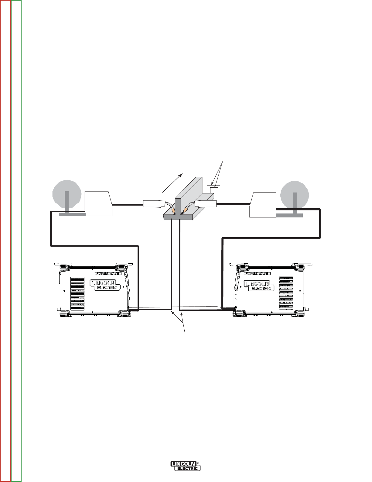
VOLTAGE SENSING
CONSIDERATIONS FOR MULTIPLE
ARC SYSTEMS
Special care must be taken when more than one arc is
welding simultaneously on a single part. Multiple arc
applications do not necessarily dictate the use of
remote work voltage sense leads, but they are strongly recommended.
If Sense Leads ARE NOT Used:
• Avoid common current paths. Current from adjacent
arcs can induce voltage into each others current
paths that can be misinterpreted by the power
sources and result in arc interference.
FIGURE A.6
DIRECTION
OF TRA VEL
If Sense Leads ARE Used:
• Position the sense leads out of the path of the weld
current. Especially any current paths common to
adjacent arcs. Current from adjacent arcs can induce
voltage into each others current paths that can be
misinterpreted by the power sources and result in arc
interference.
• For longitudinal applications, connect all work leads
at one end of the weldment and all of the work voltage sense leads at the opposite end of the weldment.
Perform welding in the direction away from the work
leads and toward the sense leads. See Figure A.6.
CONNECT ALL SENSE
LEADS AT THE END
OF THE WELD.
Return to Master TOC Return to Master TOC Return to Master TOC Return to Master TOC
Return to Section TOC Return to Section TOC Return to Section TOC Return to Section TOC
CONNECT ALL
WORK LEADS AT
THE BEGINNING
OF THE WELD.
POWER WAVE®S500

A-13 A-13
INSTALLATION
• For circumferential applications, connect all work
leads on one side of the weld joint and all of the work
voltage sense leads on the opposite side, such that
they are out of the current path. See Figure A.7.
FIGURE A.7
POWER
SOURCE
#1
WER
PO
SOURCE
#2
POWER
SOURCE
#1
WER
PO
SOURCE
#1
POWER
SOURCE
#2
WER
PO
SOURCE
#2
Return to Master TOC Return to Master TOC Return to Master TOC Return to Master TOC
Return to Section TOC Return to Section TOC Return to Section TOC Return to Section TOC
POWER WAVE®S500

A-14 A-14
INSTALLATION
CONTROL CABLE CONNECTIONS
GENERAL GUIDELINES
Genuine Lincoln control cables should be used at all
times (except where noted otherwise). Lincoln cables
are specifically designed for the communication and
power needs of the Power Wave
tems. Most are designed to be connected end to end
for ease of extension. Generally, it is recommended
that the total length not exceed 100ft. (30.5m). The use
of non-standard cables, especially in lengths greater
than 25 feet, can lead to communication problems
(system shutdowns), poor motor acceleration (poor arc
starting) and low wire driving force (wire feeding problems). Always use the shortest length of control cable
possible and DO NOT coil excess cable.
Regarding cable placement, best results will be
obtained when control cables are routed separate from
the weld cables. This minimizes the possibility of interference between the high currents flowing through the
weld cables and the low level signals in the control
cables. These recommendations apply to all communication cables including ArcLink
tions.
®
/ Power Feed™ sys-
®
and Ethernet connec-
CONNECTION BETWEEN POWER
SOURCE AND ETHERNET NETWORKS
The Power Wave®S500 is equipped with an IP67 rated
ODVA compliant RJ-45 Ethernet connector, which is
located on the rear panel. All external Ethernet equipment (cables, switches, etc.), as defined by the connection diagrams, must be supplied by the customer. It
is critical that all Ethernet cables external to either a
conduit or an enclosure are solid conductor, shielded
cat 5e cable, with a drain. The drain should be grounded at the source of transmission. For best results, route
Ethernet cables away from weld cables, wire drive control cables or any other current carrying device that can
create a fluctuating magnetic field. For additional
guidelines refer to ISO/IEC 11801. Failure to follow
these recommendations can result in an Ethernet connection failure during welding.
PRODUCT SPECIFIC INSTALLATION
INSTRUCTIONS
Connection Between Power Source and ArcLink
Compatible Wirefeeders (K1543, K2683 – ArcLink
Control Cable).
The 5-pin ArcLink control cable connects the power
source to the wire feeder. The control cable consists of
two power leads, one twisted pair for digital communication and one lead for voltage sensing. The 5-pin
ArcLink connection on the Power Wave
ed on the rear panel (See Case Back Controls in the
Operation section). The control cable is keyed and
polarized to prevent improper connection. Best results
will be obtained when control cables are routed separate from the weld cables, especially in long distance
applications. The recommended combined length of
the ArcLink control cable network should not exceed
200ft. (61.0m).
®
S500 is locat-
®
Return to Master TOC Return to Master TOC Return to Master TOC Return to Master TOC
Return to Section TOC Return to Section TOC Return to Section TOC Return to Section TOC
POWER WAVE®S500

B-1 B-1
Operation . . . . . . . . . . . . . . . . . . . . . . . . . . . . . . . . . . . . . . . . . . . . . . . . . . . . . . . . . . . . . . . . . . . . . . . . . . . . . .B-1
Safety Precautions . . . . . . . . . . . . . . . . . . . . . . . . . . . . . . . . . . . . . . . . . . . . . . . . . . . . . . . . . . . . . . . . . . . .B-2
Power-Up Sequence . . . . . . . . . . . . . . . . . . . . . . . . . . . . . . . . . . . . . . . . . . . . . . . . . . . . . . . . . . . . . . . . . .B-2
Duty Cycle . . . . . . . . . . . . . . . . . . . . . . . . . . . . . . . . . . . . . . . . . . . . . . . . . . . . . . . . . . . . . . . . . . . . . . . . . .B-2
Graphic Symbols That Appear On This Machine Or In This Manual . . . . . . . . . . . . . . . . . . . . . . . . . . . . . .B-2
Product Description . . . . . . . . . . . . . . . . . . . . . . . . . . . . . . . . . . . . . . . . . . . . . . . . . . . . . . . . . . . . . . . . . . .B-3
Recommended Processes And Equipment . . . . . . . . . . . . . . . . . . . . . . . . . . . . . . . . . . . . . . . . . . . . . . . . .B-3
Equipment Limitations . . . . . . . . . . . . . . . . . . . . . . . . . . . . . . . . . . . . . . . . . . . . . . . . . . . . . . . . . . . . . . . . .B-3
Design Features . . . . . . . . . . . . . . . . . . . . . . . . . . . . . . . . . . . . . . . . . . . . . . . . . . . . . . . . . . . . . . . . . . . . . .B-4
TABLE OF CONTENTS - OPERATION SECTION
Case Front Controls . . . . . . . . . . . . . . . . . . . . . . . . . . . . . . . . . . . . . . . . . . . . . . . . . . . . . . . . . . . . . . . . . . .B-4
Case Back Controls . . . . . . . . . . . . . . . . . . . . . . . . . . . . . . . . . . . . . . . . . . . . . . . . . . . . . . . . . . . . . . . . . . .B-5
Common Welding Procedures . . . . . . . . . . . . . . . . . . . . . . . . . . . . . . . . . . . . . . . . . . . . . . . . . . . . . . . . . . .B-6
Definition Of Welding Modes . . . . . . . . . . . . . . . . . . . . . . . . . . . . . . . . . . . . . . . . . . . . . . . . . . . . . . . . . . . .B-6
Basic Welding Controls . . . . . . . . . . . . . . . . . . . . . . . . . . . . . . . . . . . . . . . . . . . . . . . . . . . . . . . . . . . . .B-6/B-8
Return to Master TOC Return to Master TOC Return to Master TOC Return to Master TOC
POWER WAVE®S500
B-2 B-2
OPERATION
SAFETY PRECAUTIONS
READ AND UNDERSTAND ENTIRE SECTION
BEFORE OPERATING MACHINE.
WARNING
ELECTRIC SHOCK can kill.
• Do not touch electrically live part
or electrode with skin or wet clothing.
• Insulate yourself from work and ground.
• Always wear dry insulating gloves.
• Do not operate with covers, panels or guards
removed or open.
------------------------------------------------------------------------
FUMES AND GASSES can be
dangerous.
• Keep your head out of fumes.
• Use ventilation or exhaust to
remove fumes from breathing
zone.
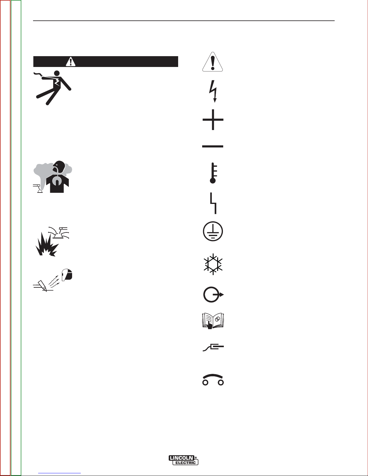
GRAPHIC SYMBOLS THAT APPEAR ON
THIS MACHINE OR IN THIS MANUAL
WARNING OR
CAUTION
DANGEROUS
VOLTAGE
POSITIVE OUTPUT
NEGATIVE OUTPUT
HIGH TEMPERATURE
STATUS
------------------------------------------------------------------------
WELDING SPARKS can cause
fire or explosion.
• Keep flammable material away.
------------------------------------------------------------------------
ARC RAYS can burn.
• Wear eye, ear and body protection.
------------------------------------------------------------------------
SEE ADDITIONAL WARNING INFORMATION
UNDER
AND in the FRONT OF THIS OPERATING MANUAL.
------------------------------------------------------------------------
ARC WELDING SAFETY PRECAUTIONS
POWER-UP SEQUENCE
When the Power Wave®S500 is powered up, it can
take as long as 30 seconds for the machine to be
ready to weld. During this time period the user interface will not be active.
DUTY CYCLE
PROTECTIVE
GROUND
COOLER
OUTPUT
OPERATORS
MANUAL
WORK
CIRCUIT BREAKER
The duty cycle is based on a ten-minute period. A 40%
duty cycle represents 4 minutes of welding and 6 minutes of idling in a ten-minute period. See the
Technical Specification section for the Power Wave
S500ʼs duty cycle ratings.
Return to Master TOC Return to Master TOC Return to Master TOC Return to Master TOC
Return to Section TOC Return to Section TOC Return to Section TOC Return to Section TOC
®
POWER WAVE®S500

B-3 B-3
OPERATION
PRODUCT DESCRIPTION
PRODUCT SUMMARY
The Power Wave®S500 is a portable multi-process
power source with high-end functionality capable of
Stick, DC TIG, MIG, Pulsed MIG and Flux-Cored welding. It is ideal for a wide variety of materials including
aluminum, stainless and nickel — where arc performance is critical.
The Power Wave
ble welding system. Like existing Power Waveʼs
software based architecture allows for future upgradeability. One significant change from the current range
of Power Wave®units is that the Ethernet communication feature is standard on the Power Wave®S500
which allows for effortless software upgrades through
Powerwavesoftware.com. The Ethernet communication also gives the Power Wave
Production Monitoring™ 2. A Devicenet option allows
the Power Wave
configurations and the Power Wave®S500 is designed
to be compatible with advanced welding modules like
STT.
®
S500 is designed to be a very flexi-
®
S500 the ability to run
®
S500 to be used in a wide range of
®
, the
RECOMMENDED PROCESSES AND
EQUIPMENT
The Power Wave®S500 is recommended for semiautomatic welding and may also be suitable for basic
hard automation applications. The Power Wave®S500
can be set up in a number of configurations, some
requiring optional equipment or welding programs.
RECOMMENDED EQUIPMENT
The Power Wave®S500 is designed to be compatible
with the current range of Power Feed™ systems
including future versions of ArcLink®feeders.
RECOMMENDED PROCESSES
The Power Wave®S500 is a high speed, multi-process
power source capable of regulating the current, voltage or power of the welding arc. With an output range
of 5 to 550 amperes, it supports a number of standard
processes including synergic GMAW, GMAW-P,
FCAW, FCAW-SS, SMAW, GTAW and GTAW-P on
various materials especially steel, aluminum and stainless.
PROCESS LIMITATIONS
The software based weld tables of the Power Wave
S500 limit the process capability within the output
range and the safe limits of the machine. In general the
processes will be limited to .030 - .052 solid steel wire,
.030 - .045 stainless wire, .035 - 1/16 cored wire and
.035 - 1/16 Aluminum wire.
EQUIPMENT LIMITATIONS
Only ArcLink compatible semiautomatic wire feeders
and users interfaces may be used. If other Lincoln wire
feeders or non-Lincoln wire feeders are used there will
be limited process capability and performance and features will be limited.
®
Return to Master TOC Return to Master TOC Return to Master TOC Return to Master TOC
Return to Section TOC Return to Section TOC Return to Section TOC Return to Section TOC
POWER WAVE®S500
B-4 B-4
OPERATION
DESIGN FEATURES
LOADED WITH STANDARD FEATURES
• Multiple process DC output range: 5 - 550 Amps.
• 200 – 600 VAC, 3 phase, 50-60Hz input power.
• New and Improved Line Voltage Compensation holds
the output constant over wide input voltage fluctuations.
• Utilizes next generation microprocessor control,
based on the ArcLink
• State of the art power electronics technology yields
superior welding capability.
• Electronic over current protection.
• Input over voltage protection.
• F.A.N. (fan as needed). Cooling fan only runs when
needed.
• Thermostatically protected for safety and reliability.
• Ethernet connectivity.
• Panel mounted Status and Thermal LED indicators
facilitate quick and easy troubleshooting.
®
platform.
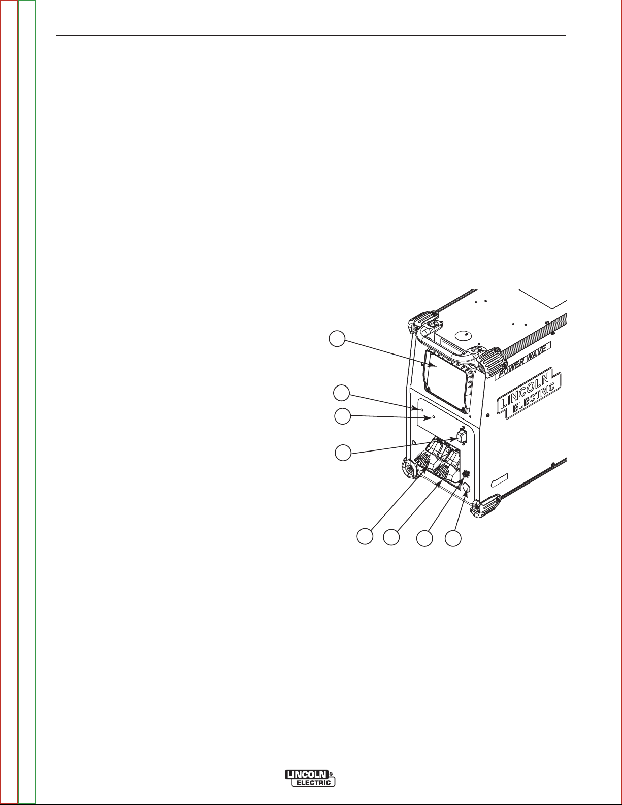
CASE FRONT CONTROLS
See Figure B.1
1. USER INTERFACE (optional)
2. STATUS LED - (See Troubleshooting section for
operational functions)
3. THERMAL LED - Indicates when machine has ther-
mal fault.
4. POWER SWITCH - Controls power to the Power
5. NEGATIVE WELD OUTPUT
6. POSITIVE WELD OUTPUT
7. WORK SENSE LEAD CONNECTOR
8. 12-PIN CONNECTOR (Optional)
Wave
1
®
S500.
FIGURE B.1
• Potted PC boards for enhanced ruggedness/reliability.
• Enclosure reinforced with heavy duty aluminum
extrusions for mechanical toughness.
• Waveform Control Technology™ for good weld
appearance and low spatter, even when welding nickel alloys.
• Sync Tandem installed.
2
3
4
5
6
8
7
Return to Master TOC Return to Master TOC Return to Master TOC Return to Master TOC
Return to Section TOC Return to Section TOC Return to Section TOC Return to Section TOC
POWER WAVE®S500
B-5 B-5
OPERATION
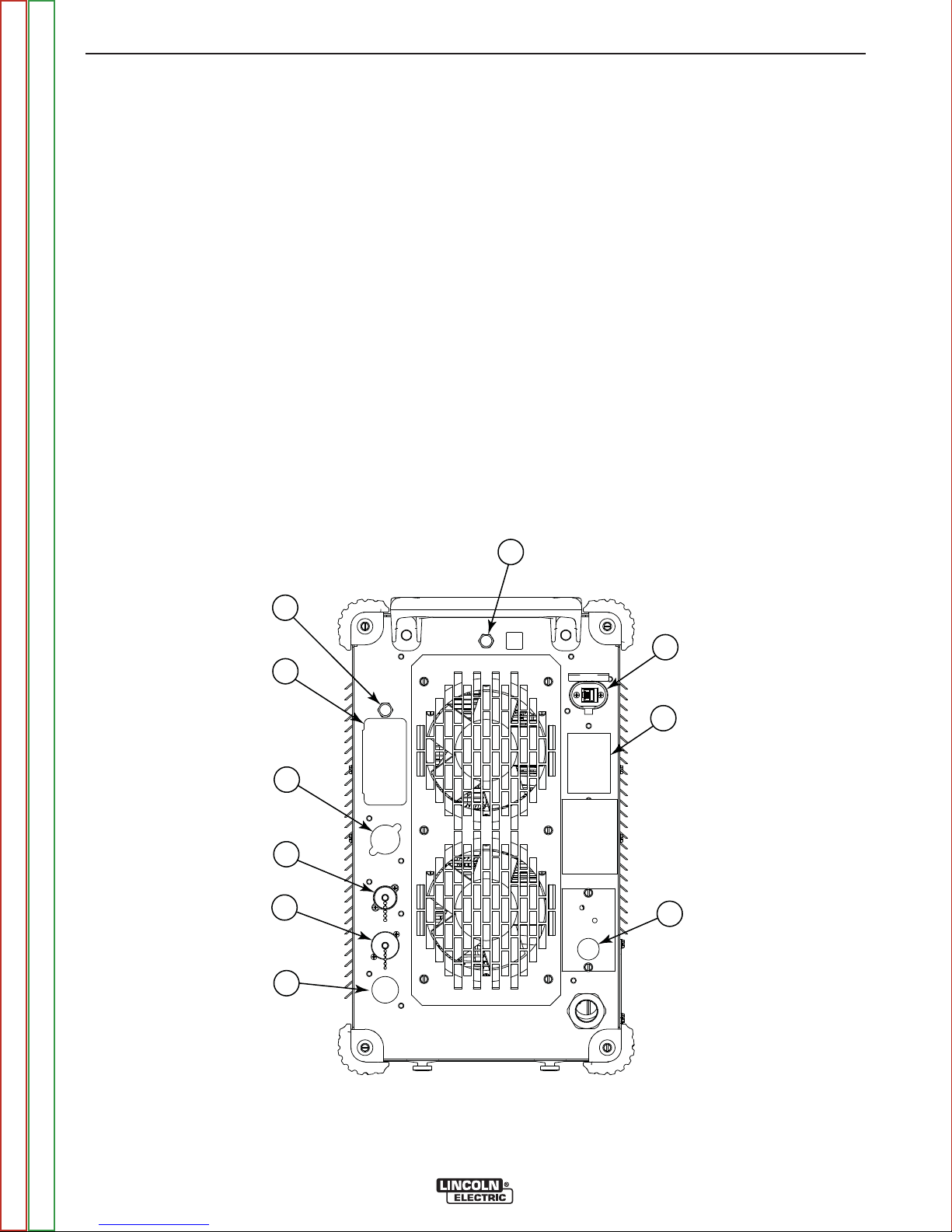
CASE BACK CONTROLS
(See Figure B.2)
1. 115 VAC CIRCUIT BREAKER
2. 115 VAC RECEPTACLES
3. RESERVED FOR FUTURE DEVELOPMENT
4. SYNC TANDEM/ STT CONNECTOR
5. Arclink CONNECTOR
6. DEVICENET KIT (optional)
7. ETHERNET
8. 40V CIRCUIT BREAKER
9. RESERVED FOR FUTURE DEVELOPMENT
10. GAS Solenoid Kit (optional)
FIGURE B.2
8
1
7
2
9
3
4
5
10
6
Return to Master TOC Return to Master TOC Return to Master TOC Return to Master TOC
Return to Section TOC Return to Section TOC Return to Section TOC Return to Section TOC
POWER WAVE®S500

B-6 B-6
OPERATION
COMMON WELDING PROCEDURES
WARNING
MAKING A WELD
The serviceability of a product or structure utilizing the welding programs is and must be the sole
responsibility of the builder/user. Many variables
beyond the control of The Lincoln Electric
Company affect the results obtained in applying
these programs. These variables include, but are
not limited to, welding procedure, plate chemistry
and temperature, weldment design, fabrication
methods and service requirements. The available
range of a welding program may not be suitable
for all applications and the build/user is and must
be solely responsible for welding program selection.
Choose the electrode material, electrode size, shielding gas and process (GMAW, GMAW-P etc.) appropriate for the material to be welded.
Select the weld mode that best matches the desired
welding process. The standard weld set shipped with
the Power Wave
common processes that will meet most needs. If a
special weld mode is desired, contact a local Lincoln
Electric sales representative.
All adjustments are made through the user interface.
Because of the different configuration options your
system may not have all of the following adjustments.
See Accessories section for Kits and Options available to use with the Power Wave
®
S500 encompasses a wide range of
®
S500.
BASIC WELDING CONTROLS
WELD MODE
Selecting a weld mode determines the output characteristics of the Power Wave®power source. Weld
modes are developed with a specific electrode material, electrode size and shielding gas. For a more complete description of the weld modes programmed into
the Power Wave
Set Reference Guide supplied with the machine or
available at www.powerwavesoftware.com.
WIRE FEED SPEED (WFS)
In synergic welding modes (synergic CV, GMAW-P),
WFS is the dominant control parameter. The user
adjusts WFS according to factors such as wire size,
penetration requirements, heat input, etc. The Power
®
Wave
voltage and current according to settings contained in
the POWER WAVE
In non-synergic modes, the WFS control behaves like
a conventional power source where WFS and voltage
are independent adjustments. Therefore, to maintain
proper arc characteristics, the operator must adjust the
voltage to compensate for any changes made to the
WFS.
S500 then uses the WFS setting to adjust the
AMPS
In constant current modes, this control adjusts the
welding amperage.
®
S500 at the factory, refer to the Weld
®
.
Return to Section TOC Return to Section TOC Return to Section TOC Return to Section TOC
DEFINITION OF WELDING MODES
NON-SYNERGIC WELDING MODES
• A Non-synergic welding mode requires all welding
process variables to be set by the operator.
SYNERGIC WELDING MODES
• A Synergic welding mode offers the simplicity of sin-
gle knob control. The machine will select the correct
voltage and amperage based on the Wire Feed
Speed (WFS) set by the operator.
Return to Master TOC Return to Master TOC Return to Master TOC Return to Master TOC
VOLTS
In constant voltage modes, this control adjusts the
welding voltage.
TRIM
In pulse synergic welding modes, the Trim setting
adjusts the arc length. Trim is adjustable from 0.50 to
1.50. 1.00 is the nominal setting and is a good starting
point for most conditions.
ULTIMARC™ CONTROL
UltimArc™ Control allows the operator to vary the arc
characteristics. UltimArc™ Control is adjustable from
–10.0 to +10.0 with a nominal setting of 0.0.
POWER WAVE®S500
B-7 B-7
OPERATION
SMAW (STICK) WELDING
The welding current and Arc Force settings can be set
through a Power Feed™ 10M or Power Feed™ 25M
wire feeder. Alternatively an optional Stick / Tig UI can
be installed into the power source to control these settings locally.
In a SMAW (STICK mode), Arc Force can be adjusted.
It can be set to the lower range for a soft and less penetrating arc characteristic (negative numeric values) or
to the higher range (positive numeric values) for a crisp
and more penetrating arc. Normally, when welding with
cellulosic types of electrodes (E6010, E7010, E6011),
a higher energy arc is required to maintain arc stability. This is usually indicated when the electrode sticks to
the work-piece or when the arc becomes unstable during manipulative technique. For low hydrogen types of
electrodes (E7018, E8018, E9018, etc.) a softer arc is
usually desirable and the lower end of the Arc Control
suits these types of electrodes. In either case the arc
control is available to increase or decrease the energy
level delivered to the arc.
GTAW (TIG) WELDING
The nominal preprogrammed voltage is the best average voltage for a given wire feed speed, but may be
adjusted to preference. When the wire feed speed
changes, the Power Wave®S500 automatically adjusts
the voltage level correspondingly to maintain similar
arc characteristics throughout the WFS range.
NON SYNERGIC CV
In non-synergic modes, the WFS control behaves
more like a conventional CV power source where WFS
and voltage are independent adjustments. Therefore
to maintain the arc characteristics, the operator must
adjust the voltage to compensate for any changes
made to the WFS.
ALL CV MODES
Pinch adjusts the apparent inductance of the wave
shape. The “pinch” function is inversely proportional to
inductance. Therefore, increasing Pinch Control
greater than 0.0 results in a crisper arc (more spatter)
while decreasing the Pinch Control to less than 0.0
provides a softer arc (less spatter).
The welding current can be set through a Power
Feed™ 10M or Power Feed™ 25M wire feeder.
Alternatively an optional Stick / Tig UI can be installed
into the power source to control these settings locally.
The TIG mode features continuous control from 5 to
550 amps with the use of an optional foot amptrol. The
Power Wave
TIG mode or Scratch start TIG mode.
®
S500 can be run in either a Touch Start
CONSTANT VOLTAGE WELDING
SYNERGIC CV
For each wire feed speed, a corresponding voltage is
preprogrammed into the machine through special software at the factory.
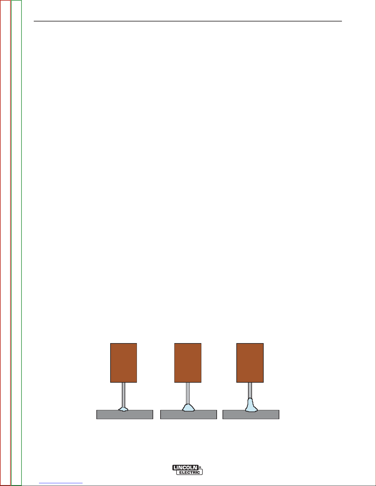
FIGURE B.3
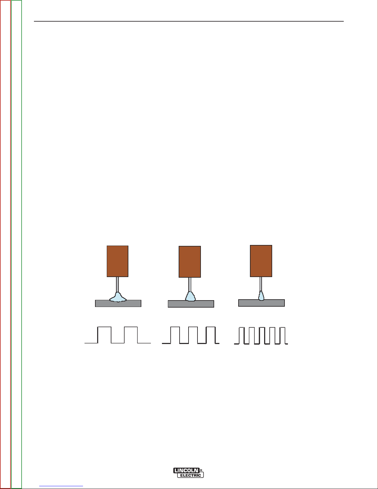
PULSE WELDING
Pulse welding procedures are set by controlling an
overall “arc length” variable. When pulse welding, the
arc voltage is highly dependent upon the waveform.
The peak current, back ground current, rise time, fall
time and pulse frequency all affect the voltage. The
exact voltage for a given wire feed speed can only be
predicted when all the pulsing waveform parameters
are known. Voltage or Trim can be adjusted.
Trim adjusts the arc length and ranges from 0.50 to
1.50 with a nominal value of 1.00. Trim values greater
than 1.00 increase the arc length, while values less
than 1.00 decrease the arc length. See Figure B.3.
Trim .50
Arc Length Short
Return to Master TOC Return to Master TOC Return to Master TOC Return to Master TOC
Return to Section TOC Return to Section TOC Return to Section TOC Return to Section TOC
Trim 1.00
Arc Length Medium
POWER WAVE®S500
Trim 1.50
Arc Length Long
B-8 B-8
OPERATION
Most pulse welding programs are synergic. As the wire
®
feed speed is adjusted, the Power Wave
S500 will
automatically recalculate the waveform parameters to
maintain similar arc properties.
The Power Wave
®
S500 utilizes “adaptive control” to
compensate for changes in the electrical stick-out
while welding. (Electrical stick-out is the distance from
the contact tip to the work piece.) The Power Wave
S500 waveforms are optimized for a 0.75” stick-out.
The adaptive behavior supports a range of stick-outs
from 0.50 to 1.25”. At very low or high wire feed
speeds, the adaptive range may be less due to reaching physical limitations of the welding process.
UltimArc™ Control adjusts the focus or shape of the
arc. UltimArc™ Control is adjustable from -10.0 to
+10.0 with a nominal setting of 0.0. Increasing the
UltimArc™ Control increases the pulse frequency and
background current while decreasing the peak current.
This results in a tight, stiff arc used for high speed
sheet metal welding. Decreasing the UltimArc™
Control decreases the pulse frequency and background current while increasing the peak current. This
results in a soft arc good for out of position welding.
See Figure B.4.
®
UltimArc™ Control -10 .0
Low F requency, Wi de
FIGURE B.4
UltimArc™ Control
Medium Frequency and Width
OF F
UltimArc™ Control
High Frequency , Focused
+10.0
Return to Master TOC Return to Master TOC Return to Master TOC Return to Master TOC
Return to Section TOC Return to Section TOC Return to Section TOC Return to Section TOC
POWER WAVE®S500
 Loading...