

Lincoln Electric Power Wave S350, Power Wave S500 Operator's Manual
IM2056
08/2017
REV01
POWER WAVE® ADVANCED MODULE
& ADVANCED MODULE ALUMINUM
OPERATOR’S MANUAL
ENGLISH
22801 St. Clair Ave., Cleveland Ohio 44117-1199 USA
THE LINCOLN ELECTRIC COMPANY
www.lincolnelectric.eu

THE LINCOLN ELECTRIC COMPANY
EC DECLARATION OF CONFORMITY
Manufacturer and technical
documentation holder:
EC Company:
Hereby declare that welding equipment: Power Wave
Product number:
Is in conformity with Council Directives
and amendments:
Standards:
CE marking affixed in: 2014
Samir Farah, Manufacturer
Compliance Engineering Manager
11 July 2017 19 July 2017
MCD431c
The Lincoln Electric Company
22801 St. Clair Ave.
Cleveland Ohio 44117-1199 USA
Lincoln Electric Europe S.L.
c/o Balmes, 89 - 8
0 2a
08008 Barcelona SPAIN
®
Advanced Module
K2912
K4192
(numbers may also contain prefixes and suffixes)
Electromagnetic Compatibility (EMC) Directive 2014/30/EU
Low Voltage Directive 2014/35/EU
EN 60974-1:2012, Arc Welding Equipment – Part 1: Welding
Power Sources
EN 60974-3:2007, Arc Welding Equipment – Part 3: Arc
Striking and Stabilizing Devices
EN 60974-10:2014 Arc Welding Equipment – Part 10:
Electromagnetic compatibility (EMC) requirements
Jacek Stefaniak, European Community Representative
European Product Manager Equipment
English English
I

THANKS! For having chosen the QUALITY of the Lincoln Electric products.
Please Examine Package and Equipment for Damage. Claims for material damaged in shipment must be notified
immediately to the dealer.
For future reference record in the table below your equipment identification information. Model Name, Code &
Serial Number can be found on the machine rating plate.
Model Name:
………………...…………………………….…………………………………………………………………………………………..
Code & Serial number:
………………….……………………………………………….. …………………………………………………….……………..
Date & Where Purchased:
…………………………………………………………………... ……………………….…………………………………………..
ENGLISH INDEX
Technical Specifications ...................................................................................................................................................... 1
Electromagnetic Compatibility (EMC) ................................................................................................................................. 2
Safety .................................................................................................................................................................................. 3
Installation and Operator Instructions ................................................................................................................................. 4
Spare Parts ....................................................................................................................................................................... 29
Authorized Service Shops Location .................................................................................................................................. 29
Electrical Schematic .......................................................................................................................................................... 30
Suggested Accessories ..................................................................................................................................................... 31
12/05
English English
II

V
Technical Specifications
POWER WAVE® ADVANCED MODULE (K2912-1) & ADVANCED MODULE ALUMINUM (K4192-1*)
INPUT VOLTAGE AND CURRENT
oltage Input Amperes Notes
40Vdc 3.0
*OUTPUT CURRENT CAPACITY
Duty Cycle Amperes Notes
100% 300
* Defines capability of the output switch. the actual output current is supplied b y host power source.
Environmentally Hardened: -4°F to 104°F (-20°C to 40°C)
IP23 Insulation Class
40% 350
PHYSICAL DIMENSIONS
Height Width Depth Weight
29.2 cm 35.4cm 62.99cm 32.0kg
TEMPERATURE RANGE
Operating Temperature Range Storage Temperature Range
Environmentally
Hardened: -40°F to 185°F (-40°C to 85°C)
600A Peak (Max.)
English English
1
Electromagnetic Compatibility (EMC)
This machine has been designed in accordance with all relevant directives and standards. However, it may still generate
electromagnetic disturbances that can affect other systems like telecommunications (telephone, radio, and television) or
other safety systems. These disturbances can cause safety problems in the affected systems. Read and understand
this section to eliminate or reduce the amount of electromagnetic disturbance generated by this machine.
This machine has been designed to operate in an industrial area. To operate in a domestic area it is
necessary to observe particular precautions to eliminate possible electromagnetic disturbances. The
operator must install and operate this equipment as described in this manual. If any electromagnetic
disturbances are detected the operator must put in place corrective actions to eliminate these disturbances
with, if necessary, assistance from Lincoln Electric.
Before installing the machine, the operator must check the work area for any devices that may malfunction because of
electromagnetic disturbances. Consider the following.
Input and output cables, control cables, and telephone cables that are in or adjacent to the work area and the
machine.
Radio and/or television transmitters and receivers. Computers or computer controlled equipment.
Safety and control equipment for industrial processes. Equipment for calibration and measurement.
Personal medical devices like pacemakers and hearing aids.
Check the electromagnetic immunity for equipment operating in or near the work area. The operator must be sure
that all equipment in the area is compatible. This may require additional protection measures.
The dimensions of the work area to consider will depend on the construction of the area and other activities that are
taking place.
Consider the following guidelines to reduce electromagnetic emissions from the machine.
Connect the machine to the input supply according to this manual. If disturbances occur if may be necessary to take
additional precautions such as filtering the input supply.
The output cables should be kept as short as possible and should be positioned together. If possible connect the
work piece to ground in order to reduce the electromagnetic emissions. The operator must check that connecting
the work piece to ground does not cause problems or unsafe operating conditions for personnel and equipment.
Shielding of cables in the work area can reduce electromagnetic emissions. This may be necessary for special
applications.
WARNING
EMC classification of this product is class A in accordance with electromagnetic compatibility standard EN 60974-10 and
therefore the product is designed to be used in an industrial environment only.
WARNING
The Class A equipment is not intended for use in residential locations where the electrical power is provided by the public
low-voltage supply system. There can be potential difficulties in ensuring electromagnetic compatibility in those locations,
due to conducted as well as radio-frequency disturbances.
01/11
The EMC classification of the Power Wave
A. The Power Wave
®
Advanced Module is for industrial use only.
English English
®
Advanced Module is Industrial, Scientific and Medical (ISM) group 2, class
2
Safety
11/04
WARNING
This equipment must be used by qualified personnel. Be sure that all installation, operation, maintenance and repair
procedures are performed only by qualified person. Read and understand this manual before operating this equipment.
Failure to follow the instructions in this manual could cause serious personal injury, loss of life, or damage to this
equipment. Read and understand the following explanations of the warning symbols. Lincoln Electric is not responsible
for damages caused by improper installation, improper care or abnormal operation.
WARNING: This symbol indicates that instructions must be followed to avoid serious personal injury,
loss of life, or damage to this equipment. Protect yourself and others from possible serious injury or
death.
READ AND UNDERSTAND INSTRUCTIONS: Read and understand this manual before operating
this equipment. Arc welding can be hazardous. Failure to follow the instructions in this manual could
cause serious personal injury, loss of life, or damage to this equipment.
ELECTRIC SHOCK CAN KILL: Welding equipment generates high voltages. Do not touch the
electrode, work clamp, or connected work pieces when this equipment is on. Insulate yourself from
the electrode, work clamp, and connected work pieces.
ELECTRICALLY POWERED EQUIPMENT: Turn off input power using the disconnect switch at the
fuse box before working on this equipment. Ground this equipment in accordance with local electrical
regulations.
ELECTRICALLY POWERED EQUIPMENT: Regularly inspect the input, electrode, and work clamp
cables. If any insulation damage exists replace the cable immediately. Do not place the electrode
holder directly on the welding table or any other surface in contact with the work clamp to avoid the
risk of accidental arc ignition.
ELECTRIC AND MAGNETIC FIELDS MAY BE DANGEROUS: Electric current flowing through any
conductor creates electric and magnetic fields (EMF). EMF fields may interfere with some
pacemakers, and welders having a pacemaker shall consult their physician before operating this
equipment.
CE COMPLIANCE: This equipment complies with the European Community Directives.
FUMES AND GASES CAN BE DANGEROUS: Welding may produce fumes and gases hazardous to
health. Avoid breathing these fumes and gases. To avoid these dangers the operator must use
enough ventilation or exhaust to keep fumes and gases away from the breathing zone.
ARC RAYS CAN BURN: Use a shield with the proper filter and cover plates to protect your eyes from
sparks and the rays of the arc when welding or observing. Use suitable clothing made from durable
flame-resistant material to protect you skin and that of your helpers. Protect other nearby personnel
with suitable, non-flammable screening and warn them not to watch the arc nor expose themselves to
the arc.
WELDING SPARKS CAN CAUSE FIRE OR EXPLOSION: Remove fire hazards from the welding
area and have a fire extinguisher readily available. Welding sparks and hot materials from the welding
process can easily go through small cracks and openings to adjacent areas. Do not weld on any
tanks, drums, containers, or material until the proper steps have been taken to insure that no
flammable or toxic vapors will be present. Never operate this equipment when flammable gases,
vapors or liquid combustibles are present.
WELDED MATERIALS CAN BURN: Welding generates a large amount of heat. Hot surfaces and
materials in work area can cause serious burns. Use gloves and pliers when touching or moving
materials in the work area.
SAFETY MARK: This equipment is suitable for supplying power for welding operations carried out in
an environment with increased hazard of electric shock.
English English
3
CYLINDER MAY EXPLODE IF DAMAGED: Use only compressed gas cylinders containing the
correct shielding gas for the process used and properly operating regulators designed for the gas and
pressure used. Always keep cylinders in an upright position securely chained to a fixed support. Do
not move or transport gas cylinders with the protection cap removed. Do not allow the electrode,
electrode holder, work clamp or any other electrically live part to touch a gas cylinder. Gas cylinders
must be located away from areas where they may be subjected to physical damage or the welding
process including sparks and heat sources.
MOVING PARTS ARE DANGEROUS: There are moving mechanical parts in this machine, which
can cause serious injury. Keep your hands, body and clothing away from those parts during machine
starting, operating and servicing.
EQUIPMENT WEIGHT OVER 30kg: Move this equipment with care and with the help of another
person. Lifting may be dangerous for your physical health.
The manufacturer reserves the right to make changes and/or improvements in design without upgrade at the same time
the operator’s manual.
Installation and Operator Instructions
Read this entire section before installation or operation
of the machine.
General Description
The Power Wave® Advanced Module is an accessory
enabling compatible power sources to perform the DC+,
DC-, AC, STT or any combination of these functions. It
is intended for use with medium range “S” – series
Power Wave power sources such as the S350 or S500.
The Advanced Module will limit the output of an S500
(CE) or R500 to a maximum of 350 amps, regardless of
process. The module itself is a low profile pedestal,
designed to seamlessly integrate with compatible power
sources and water coolers.
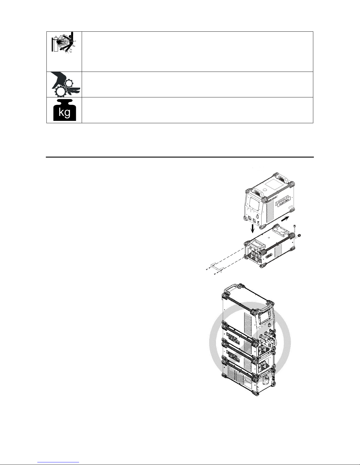
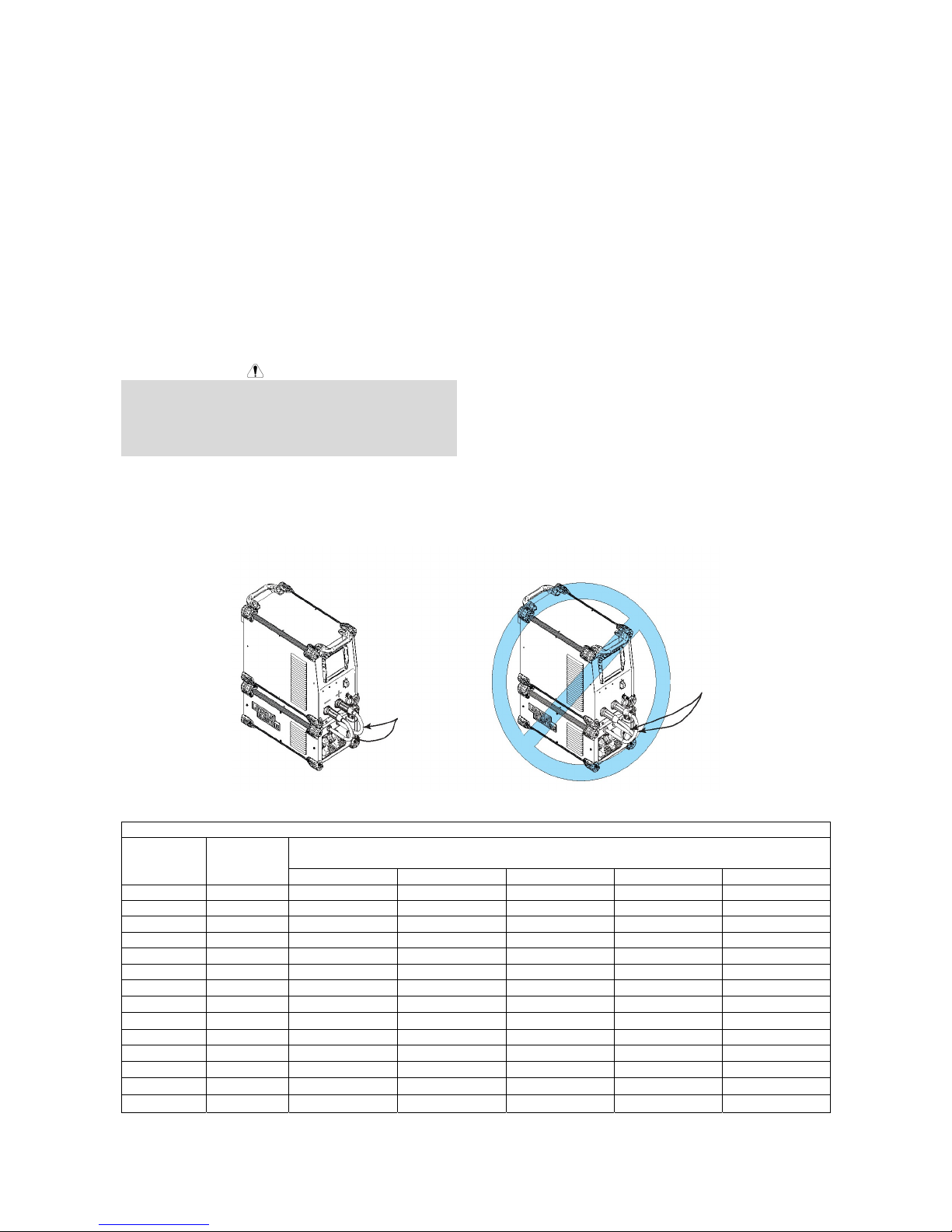
Location, Environment and Mounting
(see Figure #1)
Mount the Advanced Module directly to the bottom of a
compatible Power Wave
utilizing the quick lock mechanism as shown. The
Advanced Module will operate in harsh environments
and can be used outdoors. Even so, it is important that
simple preventative measures are followed in order to
assure long life and reliable operation.
The machine must be located where there is free
circulation of clean air such that movement into and
out of the louvers will not be restricted.
Dirt and dust that can be drawn into the machine
should be kept to a minimum. The use of air filters
on the air intake is not recommended because
normal air flow may be restricted. Failure to
observe these precautions can result in excessive
operating temperatures and nuisance shutdown.
Keep the machine dry. Shelter from rain and snow.
Do not place on wet ground or in puddles.
Do not mount the Power Wave
source and Advanced Module combination over
combustible surfaces. Where there is a combustible
surface directly under stationary or fixed electrical
equipment, that surface shall be covered with a
steel plate at least 1.6mm thick, which shall extend
not less than 150mm beyond the equipment on all
sides.
®
“S” series power source
®
“S” series power
Figure #1
STACK HEIGHT NOT TO EXCEED ONE POWER
SOURCE AND TWO MODULES.
Figure #2
English English
4
Machine Grounding and High
Frequency Interference Protection
The host power source must be earth grounded! See
your local and national electrical codes for proper
grounding methods.
The Advanced Module utilizes a high frequency impulse
to initiate the arc of selected GTAW (TIG) welding
procedures. Although the power of this impulse is
significantly less than traditional arc stabilization circuits,
it is best to locate the power source and Advanced
Module away from radio controlled machinery as it may
adversely affect the operation of the RF controlled
equipment, which may result in bodily injury or damage
to the equipment.
The high frequency starting impulse may also cause
radio, TV and electronic equipment interference
problems. These problems may be the result of radiated
interference. Proper grounding methods can reduce or
eliminate radiated inter- ference.
Radiated interference can develop in the following four
ways:
1. Direct interference radiated from the welder.
2. Direct interference radiated from the welding leads.
3. Direct interference radiated from feedback into the
power lines.
4. Interference from re-radiation of “pickup” by
ungrounded metallic objects.
Keeping these contributing factors in mind, installing
equipment per the following instructions should minimize
problems.
1. Keep the welder power supply lines as short as
possible and enclose as much of them as possible
in rigid metallic conduit or equivalent shielding for a
distance of 50 feet (15.2m). There should be good
electrical contact between this conduit and the
welder case ground. Both ends of the conduit
should be connected to a driven ground and the
entire length should be continuous.
2. Keep the work and electrode leads as short as
possible and as close together as possible. Lengths
should not exceed 7.6m. Tape the leads together
when practical.
3. Be sure the torch and work cable rubber coverings
are free of cuts and cracks that allow high frequency
leakage.
4. Keep the torch in good repair and all connections
tight to reduce high frequency leakage.
5. The work piece must be connected to an earth
ground close to the work clamp, using one of the
following methods:
A metal underground water pipe in direct
contact with the earth for ten feet or more.
A 19mm galvanized pipe or a 16mm solid gal-
vanized iron, steel or copper rod driven at least
eight feet into the ground.
The ground should be securely made and the grounding
cable should be as short as possible using cable of the
same size as the work cable, or larger. Grounding to the
building frame elec trical conduit or along pipe system
can result in re-radiation, effectively making these
members radiating antennas.
6. Keep cover and all screws securely in place.
7. Electrical conductors within 15.2m of the welder
should be enclosed in grounded rigid metallic
conduit or equivalent shielding, wherever possible.
Flexible metallic conduit is generally not suitable.
8. When the welder is enclosed in a metal building, the
metal building should be connected to several good
earth driven electrical grounds around the periphery
of the building.
Failure to observe these recommended installation
procedures can cause radio or TV and electronic
equipment interference problems and result in
unsatisfactory welding performance resulting from lost
high frequency power.
Stacking
Stacking of the Power Wave® Advanced Module shall
not exceed a power source above and one module
below.
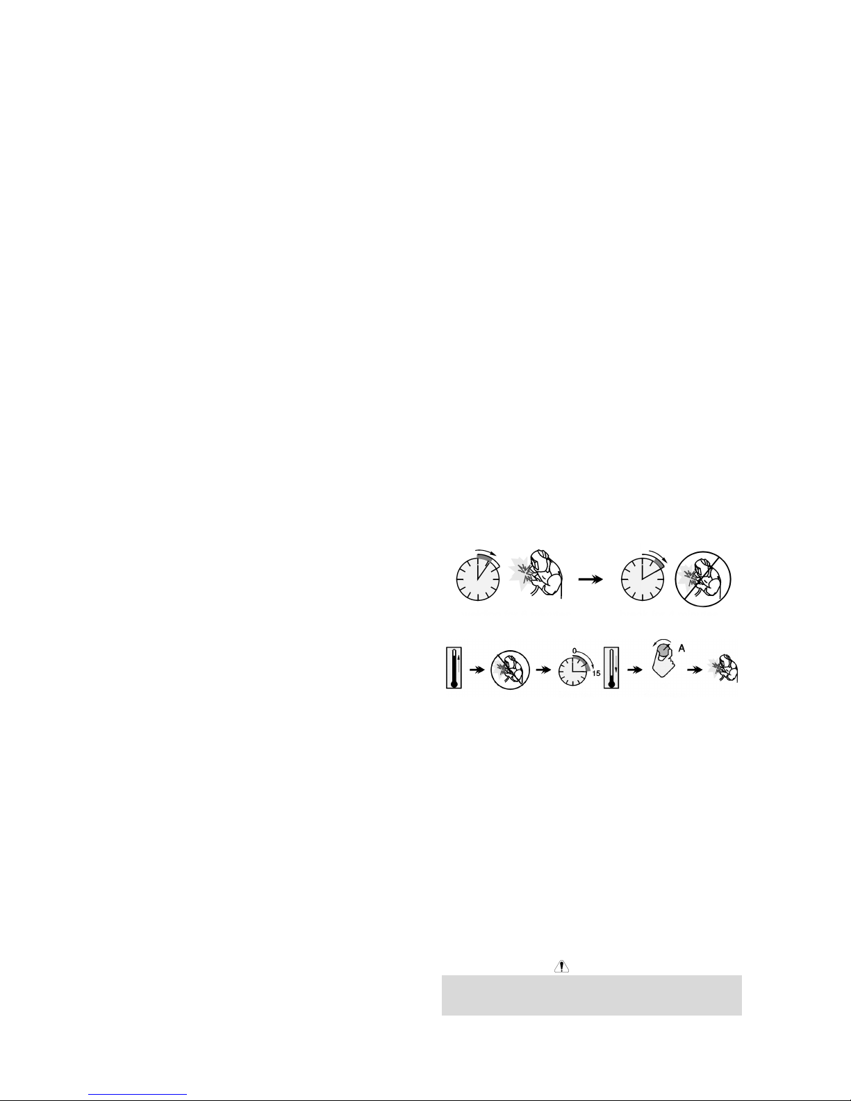
Duty Cycle
The Advanced Module is rated at 300 amps at a 100%
duty cycle. It is further rated to support 350 amps at 40%
duty cycle. The duty cycle is based on 10 minute period.
A 40% duty cycle represents 4 minutes of welding and 6
minutes of idling in a ten-minute period.
Note: the Advanced Module is capable of withstanding a
peak output current of 600 amps. The allowable
maximum average output current is time dependant, and
ultimately limited by the host power source.
Example: 40% Duty Cycle:
Welding for 4 minutes. Break for 6 minutes.
Minutes or decrease
Duty Cycle
Control Cable Connections
General guidelines
Genuine Lincoln control cables should be used at all
times (except where noted otherwise). Lincoln cables
are specifically designed for the communication and
power needs of the Power Wave
designed to be connected end to end for ease of
extension. Generally, it is recommended that the total
length not exceed 30.5 m. The use of non-standard
cables, especially in lengths greater than 25 feet, can
lead to communication problems (system shutdowns),
poor motor acceleration (poor arc starting), and low wire
driving force (wire feeding problems). Always use the
shortest length of control cable possible, and DO NOT
coil excess cable.
WARNING
Regarding cable placement, best results will be obtained
when control cables are routed separate from the weld
cables. This minimizes the possibility of interference
®
systems. Most are
English English
5

between the high currents flowing through the weld
cables, and the low level signals in the control cables.
These recommendations apply to all communication
cables including ArcLink® connections.
Special Considerations for High
Frequency GTAW (TIG) Welding
Although the equipment has been designed to withstand
the high frequency starting impulse, special care should
be taken to isolate this energy from the control signals of
the welding system and other equipment. The following
guidelines apply:
Follow the recommendations in the Machine
Grounding and High Frequency Interference
Protection section of this document.
Locate the control cables and adjacent equipment
away from the weld cables and TIG torch.
Consider optical isolation for critical applications via
the Ethernet interface on the power source (such as
ArcLink XT, Production Monitoring, etc.). Ethernet to
fiber media con- verters are commercially available,
and will significantly improve the electrical and
magnetic interference immunity of these signals.
Connection between Power Source and
Advanced Module (Arclink
®
, Voltage
Sense and Differential I/O Pigtails)
The pigtail connections on the Advanced Module include
all signal and power lines required for proper operation.
With the Advanced Module securely fastened to the
power source, connect the pigtails to their respective
receptacles on the back and front of the power source
per the connection diagrams located in this document.
Arclink Pigtail (5 pin)
Provides power to the Advanced Module as well as a
digital link for system information.
Voltage Sense Pigtail (4 pin)
Provides accurate voltage feedback to the power source
from either the output studs of the module or remote
sense lead locations based on the process.
Differential I/O Pigtail (6 pin)
Provides high speed control signals for polarity and STT
function.
Special Instructions
CE machines:
A special ArcLink
provided with the Advanced Module CE Kit (K3980-1) for
installation into the host power source. Follow the
instructions provided with the kit. (reference instruction
sheet M22499)
Power Wave S350 (Code 11589)
Some earlier vintage S350 power sources may not
include a 6 pin Differential I/O receptacle. If the
receptacle is not present on the host power source,
contact the Lincoln Electric Service Department to obtain
an S350/STT Retrofit Kit (S28481).
Connection between Power Source and
Advanced Module to Arclink
feeders (K1543 or K2683 Arclink
®
and Differential I/O receptacle kit is
®
wire
®
Control Cable)
The K2912-1 Advanced Module includes an ArcLink®
output receptacle for connection to compatible wire
feeders. The 5 pin ArcLink
lower rear portion of the Advanced Module. The control
cable is keyed and polarized to prevent improper
connection.
Best results will be obtained when control cables are
routed separate from the weld cables, especially in long
distance applications. The recommended combined
length of the ArkLink
exceed 200ft.
CE machines:
S350 and S500 CE Power Source have an ArcLink
output receptable located on the case front. The ArcLink
wire feeder can be attached to either the receptable on
the power source case front or Advanced Module case
back.
®
receptacle is located on the
®
control cable network should not
English English
6
Electrode and Work Connections
Connect the positive and negative input connections and
electrode and work output cables per the connection
diagrams included in this document. Size and route the
cables per Table 1.
Wire feeders should always be connected to the
GMAW elec- trode stud.
TIG (GTAW) torches and Stick (SMAW) holders
should always be connected to the GTAW/SMAW
electrode.
The workpiece should always be connected to the
work stud.
The output polarity is automatically configured
based on the selected weld mode. There is no need
to reverse the output cables.
WARNING
Never reverse the polarity at the input of the Advanced
Module (DO NOT connect the negative stud of the
power source to the positive input of the Advanced
Module). Although this will not damage the Advanced
Module, it will prevent welding output.
For additional Safety information regarding the electrode
and work cable set-up, See the standard “SAFETY
INFORMATION” located in the front of the Instruction
Manuals.
CORRECT
INPUT
CONNECTION
LEAD POLARITY
Table 1
AMPERES
200 60 35mm2 35mm2 35mm2 50mm2 70mm2
200 100 35mm2 35mm2 35mm2 50mm2 70mm2
225 20 25mm2 35mm2 25mm2 50mm2 70mm2
225 40 & 30 35mm2 35mm2 35mm2 50mm2 70mm2
250 30 35mm2 35mm2 35mm2 50mm2 70mm2
250 40 35mm2 35mm2 50mm2 50mm2 70mm2
250 60 50mm2 50mm2 50mm2 50mm2
250 100 50mm2 50mm2 50mm2 50mm2 70mm2
300 60 50mm2 50mm2 50mm2 70mm2 70mm2
350 100 70mm2 70mm2 70mm2 70mm2 95mm2
350 60 70mm2 70mm2 70mm2 70mm2 95mm2
400 60 70mm2 70mm2 70mm2 95mm2 120mm2
400 100
500 60
** Tabled values are for operation at ambient temperatures of 104°F(40°C) and below. Applications above 104°F(40°C)
may require cables larger than recommended, or cables rated higher than 167°F(75°C).
PERCENT
DUTY
CYCLE
CABLE SIZES FOR COMBINED LENGTHS OF ELECTRODE AND WORK CABLES
(RUBBER COVERED COPPER – RATED 75#C)**
0 to 15m 15 to 30m 30 to 46m 46 to 61m 61 to 76m
70mm2 95mm2 95mm2
70mm2 70mm2 95mm2
Figure #3: Correct Polarity
OUTPUT CABLE GUIDELINES
95mm2 120mm2
95mm2 120mm2
DO NOT REVERSE
INPUT CONNECTION
LEAD POLARITY
70mm2
English English
7
General Guidelines
Select the appropriate size cables per the “Output Cable
Guidelines” (See Table 1). Excessive voltage drops
caused by undersized welding cables and poor
connections often result in unsatisfactory welding
performance. Always use the largest welding cables
(electrode and work) that are practical, and be sure all
connections are clean and tight.
Note: Excessive heat in the weld circuit indicates
undersized cables and/or bad connections.
Route all cables directly to the work and wire feeder,
avoid excessive lengths and do not coil excess
cable. Route the electrode and work cables in close
proximity to one another to minimize the loop area
and therefore the inductance of the weld circuit.
Always weld in a direction away from the work
(ground) connection.
See Table 1 for copper cable sizes recommended for
different currents and duty cycles. Lengths stipulated are
the distance from the welder to work and back to the
welder again. Cable sizes are increased for greater
lengths primarily for the purpose of minimizing cable
drop.
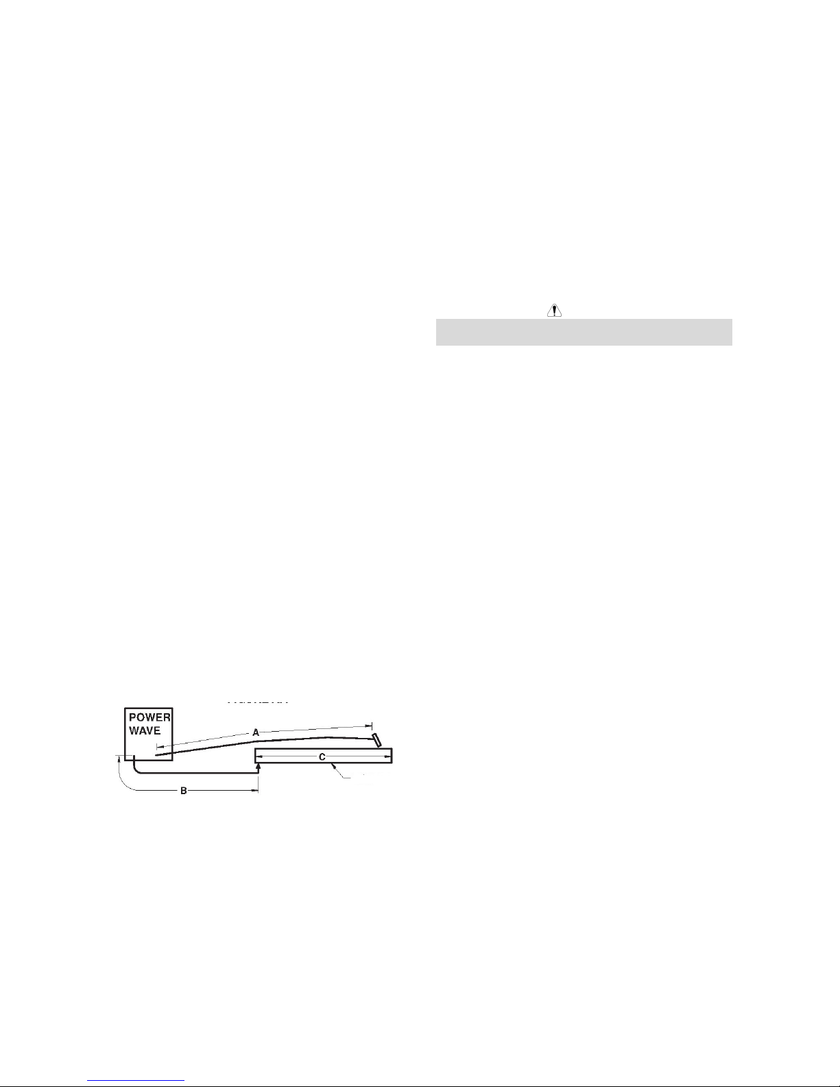
Cable Inductance and its Effects on
Welding
Excessive cable inductance will cause the welding
performance to degrade. There are several factors that
contribute to the overall inductance of the cabling system
including cable size, and loop area. The loop area is
defined by the separation distance between the
electrode and work cables, and the overall welding loop
length. The welding loop length is defined as the total of
length of the electrode cable (A) + work cable (B) + work
path (C) (see Figure #4 below). To minimize inductance
always use the appropriate size cables, and whenever
possible, run the electrode and work cables in close
proximity to one another to minimize the loop area.
Since the most significant factor in cable inductance is
the welding loop length, avoid excessive lengths and do
not coil excess cable. For long work piece lengths, a
sliding ground should be considered to keep the total
welding loop length as short as possible.
WORK
Figure #4
Remote Sense Lead Connections
Voltage Sensing Overview
Certain welding process requires the use of remote
voltage sense leads to more accurately monitor the
conditions of the arc. These leads originate in the power
source, and are connected and configured through the
Advanced Module. Consult the connection diagrams
included in this manual for detailed information.
Note:
Not all processes run through the Advanced Module do
not necessarily require sense leads, but will benefit from
their use. Consult the power source instruction manual
for recommendations.
DO NOT connect the remote electrode sense (67) lead
to the TIG (GTAW) output.
General Voltage Sensing Considerations for Multiple
Arc Systems
Special care must be taken when more than one arc is
welding simultaneously on a single part. The placement
and configuration of remote work voltage sense leads is
critical to the proper operation of multiple arc AC and
®
STT
applications.
Recommendations:
Position the sense leads out of the path of the
weld current. Especially any current paths
common to adjacent arcs. Current from adjacent
arcs can induce voltage into each others current
paths that can be misinterpreted by the power
sources, and result in arc interference.
For longitudinal applications, connect all work
leads at one end of the weldment, and all of the
work voltage sense leads at the opposite end of the
weldment. Perform welding in the direction away
from the work leads and toward the sense leads.
(See Figure #5).
WARNING
English English
8
 Loading...