

Page 1

Operator’s Manual
POWER WAVE ®MANAGER
Register your machine:
www.lincolnelectric.com/register
Authorized Service and Distributor Locator:
www.lincolnelectric.com/locator
Save for future reference
Date Purchased
Code: (ex: 10859)
Serial: (ex: U1060512345)
IM8002 | Issue D ate Jul-13
© Lincoln Global, Inc. All Rights Reserved.
Need Help? Call 1.888.935.3877
to talk to a Service Representative
Hours of Operation:
8:00 AM to 6:00 PM (ET) Mon. thru Fri.
After hours?
Use “Ask the Experts” at lincolnelectric.com
A Lincoln Service Representative will contact you
no later than the following business day.
For Service outside the USA:
Email: globalservice@lincolnelectric.com
Page 2
THANK YOU FOR SELECTING
A QUALITY PRODUCT BY
LINCOLN ELEC TRIC.
!
"
When this equipment is shipped, title passes to the purchaser upon
receipt by the carrier. Consequently, Claims for material damaged in
shipment must be made by the purchaser against the transportation
company at the time the shipment is received.
""
Lincoln arc welding and cutting equipment is designed and built with
safety in mind. However, your overall safety can be increased by
proper installation ... and thoughtful operation on your part.
DO NOT INSTALL, OPERATE OR REPAIR THIS EQUIPMENT
WITHOUT READING THIS MANUAL AND THE SAFETY PRECAUTIONS
CONTAINED THROUGHOUT. And, most importantly, think before you
act and be careful.
WARNING
This statement appears where the information must be followed
exactly to avoid serious personal injury or loss of life.
CAUTION
This statement appears where the information must be followed to
avoid minor personal injury or damage to this equipment.
"
DON’T get too close to the arc. Use
corrective lenses if necessary to
stay a reasonable distance away
from the arc.
READ and obey the Material Safety
Data Sheet (MSDS) and the warning
label that appears on all containers
of welding materials.
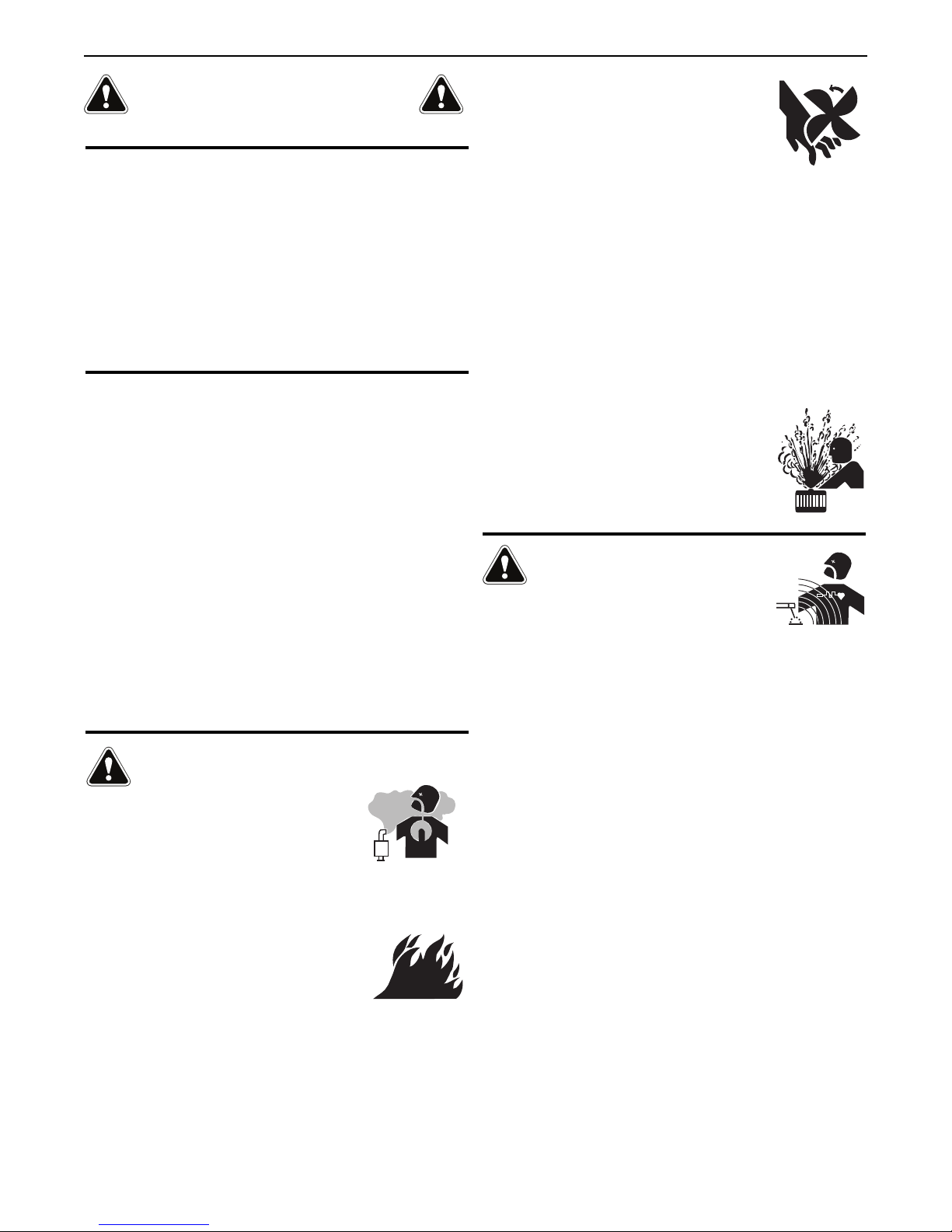
USE ENOUGH VENTILATION or
exhaust at the arc, or both, to keep
the fumes and gases from your breathing zone and the general area.
IN A LARGE ROOM OR OUTDOORS, natural ventilation may be
adequate if you keep your head out of the fumes (See below).
USE NATURAL DRAFTS or fans to keep the fumes away from your
face.
If you de velop unusual symptoms, see your supervisor. Perhaps the
welding atmosphere and ventilation system should be checked.
""
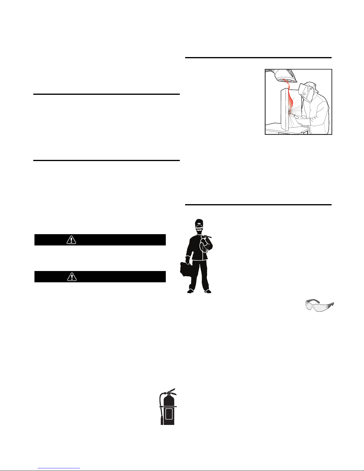
PROTECT your eyes and face with welding helmet
properly fitted and with proper grade of filter plate
(See ANSI Z49.1).
PROTECT your body from welding spatter and arc
flash with protective clothing including woolen
clothing, flame-proof apron and gloves, leather
leggings, and high boots.
PROTECT others from splatter, flash, and glare with
protective screens or barriers.
IN SOME AREAS, protection from noise may be
appropriate.
BE SURE protective equipment is in good condition.
Also, wear safety glasses in work area
AT ALL
TIMES.
SPECIA L SI TUATIONS
DO NOT WELD OR CUT containers or materials which previously had
been in contact with hazardous substances unless they are properly
cleaned. This is extremely dangerous.
DO NOT WELD OR CUT painted or plated parts unless special
precautions with ventilation have been taken. They can release highly
toxic fumes or gases.
Additional precautionary measures
PROTECT compressed gas cylinders from excessive heat, mechanical
shocks, and arcs; fasten cylinders so they cannot fall.
BE SURE cylinders are never grounded or part of an electrical circuit.
REMOVE all potential fire hazards from welding area.
ALWAYS HAVE FIRE FIGHTING EQUIPMENT READY FOR
IMMEDIATE USE AND KNOW HOW TO USE IT.
Page 3
SECTION A:
WARNINGS
CALIFORNIA PROPOSITION 65 WARNINGS
Diesel Engines
Diesel engine exhaust and some of its constituents are known
to the State of California to cause cancer, birth defects, and other
reproductive harm.
Gasoline Engines
The engine exhaust from this product contains chemicals known
to the State of California to cause cancer, birth defects, or other
reproductive harm.
#
"
" "
Read and understand the following safety highlights. For additional
safety information, it is strongly recommended that you purchase a
copy of “Safety in Welding & Cutting - ANSI Standard Z49.1” from the
American Welding Society, P.O. Box 351040, Miami, Florida 33135 or
CSA Standard W117.2-1974. A Free copy of “Arc Welding Safety”
booklet E205 is available from the Lincoln Electric Company, 22801
St. Clair Avenue, Cleveland, Ohio 44117-1199.
BE SURE THAT ALL INSTALLATION, OPERATION,
MAINTENANCE AND REPAIR PROCEDURES ARE
PERFORMED ONLY BY QUALIFIED INDIVIDUALS.
SAFETY
1.d. Keep all equipment safety guards, covers and
devices in position and in good repair.Keep
hands, hair, clothing and tools away from
V-belts, gears, fans and all other moving parts
when starting, operating or repairing
equipment.
1.e. In some cases it may be necessary to remove safety guards to
perform required maintenance. Remove guards only when
necessary and replace them when the maintenance requiring
their removal is complete. Always use the greatest care when
working near moving parts.
1.f. Do not put your hands near the engine fan. Do not attempt to
override the governor or idler by pushing on the throttle control
rods while the engine is running.
1.g. To prevent accidentally starting gasoline engines while turning
the engine or welding generator during maintenance work,
disconnect the spark plug wires, distributor cap or magneto wire
as appropriate.
1.h. To avoid scalding, do not remove the radiator
pressure cap when the engine is
hot.
ELECTRIC AND
MAGNETIC FIELDS MAY
BE DANGEROUS
2.a. Electric current flowing through any conductor
causes localized Electric and Magnetic Fields (EMF). Welding
current creates EMF fields around welding cables and welding
machines
FOR ENGINE POWERED
EQUIPMENT.
1.a. Turn the engine off before troubleshooting
and maintenance work unless the
maintenance work requires it to be running.
1.b. Operate engines in open, well-ventilated
areas or vent the engine exhaust fumes outdoors.
1.c. Do not add the fuel near an open flame
welding arc or when the engine is running.
Stop the engine and allow it to cool before
refueling to prevent spilled fuel from
vaporizing on contact with hot engine parts
and igniting. Do not spill fuel when filling
tank. If fuel is spilled, wipe it up and do not start engine until
fumes have been eliminated.
2.b. EMF fields may interfere with some pacemakers, and welders
having a pacemaker should consult their physician before
welding.
2.c. Exposure to EMF fields in welding may have other health effects
which are now not known.
2.d. All welders should use the following procedures in order to
minimize exposure to EMF fields from the welding circuit:
2.d.1. Route the electrode and work cables together - Secure
them with tape when possible.
2.d.2. Never coil the electrode lead around your body.
2.d.3. Do not place your body between the electrode and work
cables. If the electrode cable is on your right side, the
work cable should also be on your right side.
2.d.4. Connect the work cable to the workpiece as close as possible to the area being welded.
2.d.5. Do not work next to welding power source.
III
Page 4
SAFETY
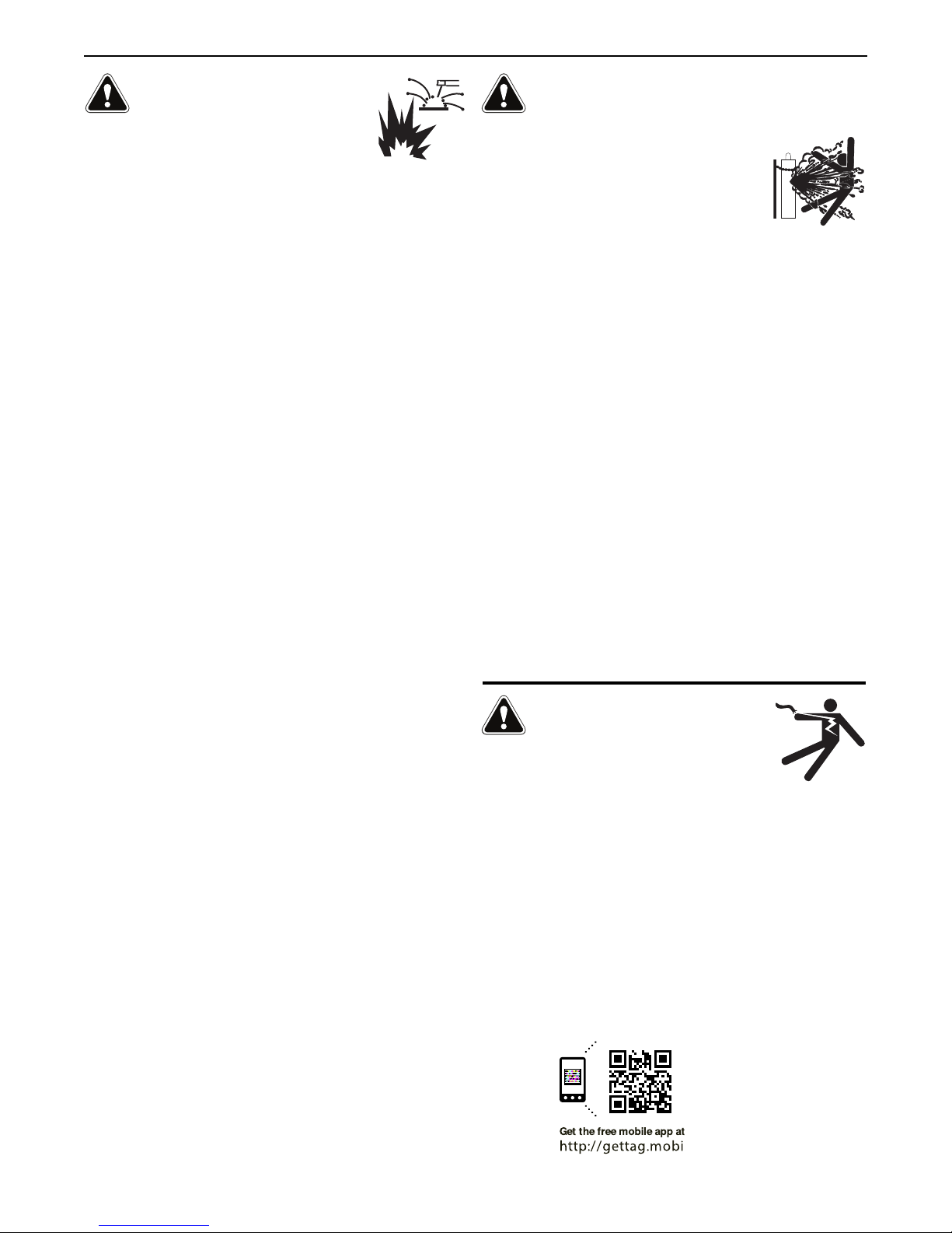
ELECTRIC SHOCK
CAN KILL.
3.a. The electrode and work (or ground) circuits are
electrically “hot” when the welder is on. Do
not touch these “hot” parts with your bare skin
or wet clothing. Wear dry, hole-free gloves to insulate hands.
3.b. Insulate yourself from work and ground using dry insulation.
Make certain the insulation is large enough to cover your full area
of physical contact with work and ground.
0$'',6,10616+(014/$.5$)(6;24(&$76,105,)
9(.',0*/756%(2(4)14/('70'(4(.(&64,&$..;
+$<$4'175&10',6,105,0'$/2.1&$6,105149+,.(
9($4,0*9(6&.16+,0*10/(6$.5647&674(557&+$5
).1145*4$6,0*5145&$))1.'59+(0,0&4$/2('
215,6,10557&+$55,66,0*-0((.,0*14.;,0*,)6+(4(
,5$+,*+4,5-1)70$81,'$%.(14$&&,'(06$.&106$&6
9,6+6+(914-2,(&(14*4170'75(6+()1..19,0*
(37,2/(06
• Semiautomatic DC Constant Voltage (Wire) Welder.
• DC Manual (Stick) Welder.
• AC Welder with Reduced Voltage Control.
3.c. In semiautomatic or automatic wire welding, the electrode,
electrode reel, welding head, nozzle or semiautomatic welding
gun are also electrically “hot”.
3.d. Always be sure the work cable makes a good electrical
connection with the metal being welded. The connection should
be as close as possible to the area being welded.
3.e. Ground the work or metal to be welded to a good electrical (earth)
ground.
3.f. Maintain the electrode holder, work clamp, welding cable and
welding machine in good, safe operating condition. Replace
damaged insulation.
3.g. Never dip the electrode in water for cooling.
3.h. Never simultaneously touch electrically “hot” parts of electrode
holders connected to two welders because voltage
two can be the total of the open circuit voltage of both
welders.
3.i. When working above floor level, use a safety belt to protect
yourself from a fall should you get a shock.
between the
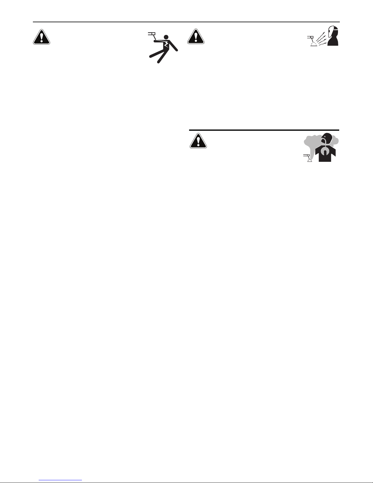
ARC RAYS CAN BURN.
4.a. Use a shield with the proper filter and cover plates to protect your
eyes from sparks and the rays of the arc when welding or
observing open arc welding. Headshield and filter lens should
conform to ANSI Z87. I standards.
4.b. Use suitable clothing made from durable flame-resistant material
to protect your skin and that of your helpers from the arc rays.
4.c. Protect other nearby personnel with suitable, non-flammable
screening and/or warn them not to watch the arc nor expose
themselves to the arc rays or to hot spatter or metal.
FUMES AND GASES
CAN BE DANGEROUS.
5.a. Welding may produce fumes and gases
hazardous to health. Avoid breathing these
fumes and gases. When welding, keep your head out of the fume.
Use enough ventilation and/or exhaust at the arc to keep fumes
and gases away from the breathing zone. +(09(.',0*
9,6+(.(&641'(59+,&+4(37,4(52(&,$.8(06,.$6,10
57&+$556$,0.(5514+$4')$&,0*5((,05647&6,105
10&106$,0(4141410.($'14&$'/,7/
2.$6('56((.$0'16+(4/(6$.514&1$6,0*59+,&+
241'7&(+,*+.;61:,&)7/(5-((2(:21574($5.19
$52155,%.($0'9,6+,0$22.,&$%.($0'
.,/,6575,0*.1&$.(:+$75614
/(&+$0,&$.8(06,.$6,100&10),0('52$&(514,0
51/(&,4&7/56$0&(5176'1145$4(52,4$614/$;
%(4(37,4(''',6,10$.24(&$76,105$4($.51
4(37,4('9+(09(.',0*10*$.8$0,<('56((.
5. b. The operation of welding fume control equipment is affected by
various factors including proper use and positioning of the
equipment, maintenance of the equipment and the specific
welding procedure and application involved. Worker exposure
level should be checked upon installation and periodically
thereafter to be certain it is within applicable OSHA PEL and
ACGIH TLV limits.
5.c. Do not weld in locations near chlorinated hydrocarbon vapors
coming from degreasing, cleaning or spraying operations. The
heat and rays of the arc can react with solvent vapors to form
phosgene, a highly toxic gas, and other irritating products.
3.j. Also see It ems 6.c. and 8.
5.d. Shielding gases used for arc welding can displace air and
injury or death. Always use enough ventilation, especially in
confined areas, to insure breathing air is safe.
5.e. Read and understand the manufacturer’s instructions for this
equipment and the consumables to be used, including the
material safety data sheet (MSDS) and follow your employer’s
safety practices. MSDS forms are available from your welding
distributor or from the manufacturer.
5.f. Also see item 1.b.
IV
cause
Page 5
SAFETY
WELDING AND CUTTING
SPARKS CAN CAUSE
FIRE OR EXPLOSION.
6.a. Remove fire hazards from the welding area. If
this is not possible, cover them to prevent the
welding sparks from starting a fire. Remember that welding
sparks and hot materials from welding can easily go through
small cracks and openings to adjacent areas. Avoid welding near
hydraulic lines. Have a fire extinguisher readily available.
6.b. Where compressed gases are to be used at the job site, special
precautions should be used to prevent hazardous situations.
Refer to “Safety in Welding and Cutting” (ANSI Standard Z49.1)
and the operating information for the equipment being used.
6.c. When not welding, make certain no part of the electrode circuit is
touching the work or ground. Accidental contact can cause
overheating and create a fire hazard.
6.d. Do not heat, cut or weld tanks, drums or containers until the
proper steps have been taken to insure that such procedures will
not cause flammable or toxic vapors from substances inside.
They can cause an explosion even though they have been
“cleaned”. For information, purchase “Recommended Safe
Practices for the Preparation for Welding and Cutting of
Containers and Piping That Have Held Hazardous Substances”,
AWS F4.1 from the American Welding Society (see address
above).
6.e. Vent hollow castings or containers before heating, cutting or
welding. They may explode.
6.f. Sparks and spatter are thrown from the welding arc. Wear oil free
protective garments such as leather gloves, heavy shirt, cuffless
trousers, high shoes and a cap over your hair. Wear ear plugs
when welding out of position or in confined places. Always wear
safety glasses with side shields when in a welding area.
6.g. Connect the work cable to the work as close to the welding area
as practical. Work cables connected to the building framework or
other locations away from the welding area increase the
possibility of the welding current passing through lifting chains,
crane cables or other alternate circuits. This can create fire
hazards or overheat lifting chains or cables until they fail.
6.h. Also see item 1.c.
CYLINDER MAY EXPLODE IF
DAMAGED.
7.a. Use only compressed gas cylinders containing
the correct shielding gas for the process used
and properly operating regulators designed for
the gas and pressure used. All hoses, fittings,
etc. should be suitable for the application and
maintained in good condition.
7.b. Always keep cylinders in an upright position securely chained to
an undercarriage or fixed support.
7.c. Cylinders should be located:
• Away from areas where they may be struck or subjected
to physical damage.
• A safe distance from arc welding or cutting operations
and any other source of heat, sparks, or flame.
7.d. Never allow the electrode, electrode holder or any other
electrically “hot” parts to touch a cylinder.
7.e. Keep your head and face away from the cylinder valve outlet
when opening the cylinder valve.
7.f. Valve protection caps should always be in place and hand tight
except when the cylinder is in use or connected for use.
7.g. Read and follow the instructions on compressed gas cylinders,
associated equipment, and CGA publication P-l, “Precautions for
Safe Handling of Compressed Gases in
Cylinders,” available
from the Compressed Gas Association 1235 Jefferson Davis
Highway, Arlington, VA 22202.
FOR ELECTRICALLY
POWERED EQUIPMENT.
8.a. Turn off input power using the disconnect
switch at the fuse box before working on the
equipment.
8.b. Install equipment in accordance with the U.S. National Electrical
Code, all local codes and the manufacturer’s recommendations.
6.I. Read and follow NFPA 51B “ Standard for Fire Prevention During
Welding, Cutting and Other Hot Work”, available from NFPA, 1
Batterymarch Park, PO box 9101, Quincy, Ma 022690-9101.
6.j. Do not use a welding power source for pipe thawing.
8.c. Ground the equipment in accordance with the U.S. National
Electrical Code and the manufacturer’s recommendations.
()(461
+662999.,0&1.0(.(&64,&&1/5$)(6;
)14$'',6,10$.5$)(6;,0)14/$6,10
Welding Safety
Interactive Web Guide
for mobile devices
V
Page 6

NOTES
Page 7

Table of Contents
Preface
Typographical Conventions Used ........................................................................................................ 1
Cross-References ....................................................................................................................... 1
Text You Type Using the Keyboard ............................................................................................ 1
Keys You Press and Buttons You Click ........................................................................................ 1
Menus You Select ...................................................................................................................... 1
Dialog Box, Application Window Titles, and Field Names .......................................................... 1
Notes, Warnings, and Tips ................................................................................................................... 2
Revision History
Introduction
System Requirements ....................................................................................................................... 1.1
Compatible Equipment ..................................................................................................................... 1.1
Connecting the Power Source
IP Addresses ..................................................................................................................................... 2.1
Ethernet Connection ........................................................................................................................ 2.1
Serial Cable Connection .................................................................................................................... 2.2
Installing Power Wave® Manager
Update Welding Power Source Firmware......................................................................................... 3.1
Installing Power Wave® Manager ..................................................................................................... 3.4
Overview of Power Wave® Manager
Setting a Preferences Folder............................................................................................................. 4.1
Connecting to the Welding Power Source ........................................................................................ 4.1
Ethernet Connection ............................................................................................................... 4.2
Finding the IP Address of a Welder ......................................................................................... 4.3
Modifying the Ethernet Settings of a Power Source ............................................................... 4.3
Serial Connection .................................................................................................................... 4.5
Navigating Power Wave® Manager .................................................................................................. 4.5
Language Selection ........................................................................................................................... 4.5
System Status
Tool Bar ............................................................................................................................................ 5.1
System Status Tab ............................................................................................................................ 5.2
Diagnostic Display ................................................................................................................... 5.2
Detailed Status Display ........................................................................................................... 5.3
Module Information Tab .................................................................................................................. 5.4
IM8002 Power Wave® Manager User Manual TOC.1
Page 8

Table of Contents
Power Source Settings
Calibration ........................................................................................................................................ 6.1
Cable Settings and Tests ................................................................................................................... 6.3
Sense Lead Settings Tab .......................................................................................................... 6.3
Weld Cable Test Tab ............................................................................................................... 6.4
Sense Lead Diagnostics Tab .................................................................................................... 6.5
Miscellaneous ................................................................................................................................... 6.7
Time Settings on the Power Source ........................................................................................ 6.8
Total Welding Lifetime ............................................................................................................ 6.8
Weld Controller ...................................................................................................................... 6.8
Network Settings
Communication Status ..................................................................................................................... 7.1
ArcLink .............................................................................................................................................. 7.2
Mapping Status Tab ................................................................................................................ 7.2
Pairing Setup ........................................................................................................................... 7.3
DeviceNet ......................................................................................................................................... 7.4
Multiple DeviceNet Modules .................................................................................................. 7.4
Status Tab ............................................................................................................................... 7.4
Configuration Tab ................................................................................................................... 7.5
Monitor Tab ............................................................................................................................ 7.9
Trace Tab .............................................................................................................................. 7.10
Weld Limits Tab .................................................................................................................... 7.11
Weld Sequencer Tab ............................................................................................................. 7.12
Ethernet .......................................................................................................................................... 7.13
Multiple Ethernet Modules ................................................................................................... 7.13
Configuration ........................................................................................................................ 7.13
Wire Feeder
Feeder Settings ................................................................................................................................. 8.1
Multiple Wire Feeders ............................................................................................................ 8.1
Settings Tab ............................................................................................................................ 8.2
Diagnostics Tab ....................................................................................................................... 8.3
User Interface ................................................................................................................................... 8.4
ltiple User Interfaces ......................................................................................................... 8.4
Mu
Setup/Security Settings Tab .................................................................................................... 8.5
Memory Settings Tab .............................................................................................................. 8.6
Tools
Lookup Error ..................................................................................................................................... 9.1
SnapShot .......................................................................................................................................... 9.2
WeldView ......................................................................................................................................... 9.3
Creating a Weld Trace ............................................................................................................. 9.4
TOC.2 Power Wave® Manager User Manual IM8002
Page 9

Weld Data Tab ........................................................................................................................ 9.5
Charts Tab ............................................................................................................................... 9.5
Backup/Restore ................................................................................................................................ 9.6
Backing Up a Power Source .................................................................................................... 9.6
Restoring a Backup ................................................................................................................. 9.7
Observer ........................................................................................................................................... 9.9
Charts Tab ............................................................................................................................... 9.9
Logged Welds Tab ................................................................................................................. 9.10
Settings Tab .......................................................................................................................... 9.11
Production Monitoring
Register........................................................................................................................................... 10.2
Saving an Installation Key File ............................................................................................... 10.2
CheckPoint™ Setup ............................................................................................................... 10.2
Diagnostics Tab ..................................................................................................................... 10.3
Configuration .................................................................................................................................. 10.3
Weld Profiles ......................................................................................................................... 10.3
Weld Profile Selection Tab .................................................................................................... 10.4
Out-of-Limit Actions Tab ....................................................................................................... 10.5
Profile Limits Tab .................................................................................................................. 10.7
Wire Package Tab ............................................................................................................... 10.11
E-mail Setup Tab ................................................................................................................. 10.12
Miscellaneous Tab .............................................................................................................. 10.15
Table of Contents
Training
Before You Begin Training a Weld .................................................................................................. 11.1
WeldScore™ ................................................................................................................................... 11.1
How WeldScore™ Works ...................................................................................................... 11.1
Where to Use WeldScore™ ................................................................................................... 11.2
Meaning of the WeldScore™ Value ....................................................................................... 11.2
Weld Profile Training ...................................................................................................................... 11.3
Welds to Train ................................................................................................................................ 11.3
Training Profiles .............................................................................................................................. 11.4
Viewing the Calculated Limits for a Weld ....
Deleting a Trained Weld from a Weld Profile ................................................................................. 11.8
Clearing Training Data .................................................................................................................... 11.8
Loading a Weld File......................................................................................................................... 11.9
Copying a Weld File ........................................................................................................................ 11.9
Troubleshooting
Cannot Connect to a Power Source ................................................................................................. A.1
IP Address or Other Ethernet Settings on the Welding Power Source Are Invalid ................. A.1
Ethernet Settings Seem Valid but Still Cannot Connect ......................................................... A.2
................................................................................... 11.7
IM8002 Power Wave® Manager User Manual TOC.3
Page 10

Table of Contents
FANUC Robots
FANUC Systems and IP Addresses ....................................................................................................B.1
FANUC® Robot Application (Prior to v7.70P/21) ..............................................................................B.1
Requirements .........................................................................................................................B.2
Setting Limits ..........................................................................................................................B.3
Adding Production Monitoring™/CheckPoint™ to Welding Programs ....................................B.3
Alarm/Alert Programs .............................................................................................................B.4
Erroneous Low Time Limit Alarms ..........................................................................................B.5
FANUC Program References (Prior to v7.70P/21) ...................................................................B.5
FANUC® Robot Application (v7.70P/21 or Later) ..............................................................................B.8
Procedure: Enabling Arc Production Monitor ...................................................................................B.8
Conditions ...............................................................................................................................B.8
Procedure ...............................................................................................................................B.8
Weld Profile Selection .............................................................................................................B.9
Part Serial Number Selection ..................................................................................................B.9
Production Monitoring™ Error Handling ...............................................................................B.10
Wire Monitor Setup Menu ....................................................................................................B.11
WeldScore™ Display .............................................................................................................B.12
Proxy Server Function for CheckPoint™ Cloud Server Data Storage .....................................B.13
Reference: $AWELEPM System Variable ..............................................................................B.15
Glossary
TOC.4 Power Wave® Manager User Manual IM8002
Page 11

Preface
Typographical Conventions Used
Before using this guide, it is important to understand the typographical conventions used to identify and
describe information.
Cross-References
Cross-references to chapters, sections, page numbers, headings, etc. are shown in an italic typeface.
e.g., Refer to Text You Type Using the Keyboard on page 1.
Text You Type Using the Keyboard
Text that you type using the keyboard is shown in a Courier typeface.
e.g., Type John Smith in the Name field.
Keys You Press and Buttons You Click
Keys that you press on the keyboard and buttons/icons that you click with the mouse are shown in a bold
sans-serif typeface.
e.g., Press Enter.
e.g., Click OK to continue.
Menus You Select
Menus and the selections you make from the menus are shown in a bold sans-serif typeface.
e.g., Select Start > Control Panel from the main computer menu.
e.g., Select Tools > Options from the menu.
Dialog Box, Application Window Titles, and Field Names
The titles of dialog boxes and application windows are shown in italics. Field names and selections made
from drop-down menus, etc. are also shown in italics.
e.g., The Print Preview window opens.
e.g., Select All Shifts from the drop-down list.
IM8002 Power Wave® Manager User Manual 1
Page 12

Preface Notes, Warnings, and Tips
Notes, Warnings, and Tips
Notes, stops and tips appear throughout the manual. They provide additional information that is important
for you to know about the topic.
NOTE | A note is an important piece of information.
STOP | You should definitely read the information in a stop table.
It could help you prevent a situation from which you cannot
recover.
TIP | A tip table helps you with some interesting or useful
information about using the program.
2 Power Wave® Manager User Manual IM8002
Page 13

Revision History
Date Change Description
July 2013 Initial Release as IM8002
IM8002 Power Wave® Manager User Manual REV.1
Page 14

Revision History
REV.2 Power Wave® Manager User Manual IM8002
Page 15

Chapter 1
Introduction
Power Wave® Manager is an application that allows you to configure and manage a multitude of settings
and configuration options within the full range of the Lincoln Electric Power Wave® line of Welding Power
Sources. It also provides in-depth diagnostics of the welding power source’s hardware and firmware to
help identify and eliminate issues with welding or configuration.
Depending on how your company is organized and who is configuring your power sources, you install
Power Wave® Manager on a computer with some kind of cable or network access to the Welding Power
Sources on the floor. This could be a laptop you use to walk the floor and configure the power sources. Or
you might choose to install the software on a central server.
System Requirements
Minimum hardware requirements for the computer on which you install Power Wave® Manager:
256 MB of system RAM
1.0 GHz processor speed
1024 x768 display resolution
50 MB free disk space
Connection to a Lincoln Electric Welding Power Source or compatible Welding Power Source
through an Ethernet network or serial (RS-232) cable
Power Wave® Manager runs under the Microsoft® .NET 2.0 framework. Therefore, it can run on the
following versions of Microsoft® operating systems:
Windows 7
Windows Vista
Windows XP Service Pack 2
Windows 2000 Service Pack 4
Windows 98 Second Edition
You must be logged in to the computer as a user with Administrator privileges in order to install Power
Wave® Manager.
Compatible Equipment
Power Wave® Manager may be used with any Welding Power Source in the Lincoln Electric Power Wave®
family that utilizes the digital controls platform. This list includes, but is not limited to:
Power Wave® 355M
Power Wave® 405M
Power Wave® 455M, 455M/STT, 455R (and corresponding CE models)
Power Wave® 655
IM8002 Power Wave® Manager User Manual 1.1
Page 16

Chapter 1. Introduction Compatible Equipment
Power Wave® AC/DC 1000, AC/DC 1000SD
Power Wave® i400
Power Wave® C300
Power Wave® S350
Power Wave® S500
The program may also be used to diagnose and modify settings in the following Welding Power Sources
outside the Power Wave® family that also use the digital common controls platform:
Invertec® V350, V450
Power MIG 300
Power MIG 350MP
NOTE | The Power Wave® Manager application is not compatible
with legacy Power Wave® models such as the Power Wave®
450. The application also does not support dual wire
feeding system.
NOTE | Not all Welding Power Source models have an Ethernet
port. However, you can upgrade some models to utilize
Ethernet by adding the Communication Interface module,
available from Lincoln Electric as K2207-2 or K2436-1
(depending on the Power Wave® model).
Connecting to robotic applications could vary from the
information in this manual. Please refer to the appropriate
Operators Manuals for more information.
1.2 Power Wave® Manager User Manual IM8002
Page 17

Chapter 2
Connecting the Power Source
Any time you need to connect the Power Wave® Manager application to a Welding Power Source to do any
configuration, you physically connect your computer to the power source using one of three methods:
A direct connection between your computer and the Welding Power Source using an Ethernet
cable from your computer to the port on the power source.
An existing company network connection.
A serial connection.
IP Addresses
An IP (Internet Protocol) address is the location of the Welding Power Source on the network (e.g.,
10.23.10.91). Any device on the network that wants to communicate with the Welding Power Source must
use the IP address to make the connection.
IP addresses can be set up as dynamic (where the computer network automatically assigns an IP address to
the machine) or as a static IP address (where an IT department assigns a specific address to each device on
the network). Power Wave® Manager can handle either scenario (page 4.3); however, it is best to check
with your local IT department for the policies used on your network.
Ethernet Connection
The Ethernet connection is the recommended method of connecting your computer to your power source.
(The Ethernet port on your computer and on the Welding Power Source is an RJ-45 jack, which resembles a
wider telephone jack.)
For an Ethernet connection, your computer can be physically connected to the Welding Power Source over
the network in one of the following ways:
Direct connection between the computer and the Welding Power Source (which may require a
crossover cable on older computers/power sources). Plug one end of the Ethernet cable to the
port on your computer and the other end into the Ethernet port of the Welding Power Source.
This is the preferred method.
Computer and Welding Power Source connected to the same network switch.
Computer and Welding Power Source on the same corporate network (may include switches
and routers)
NOTE | Not all Welding Power Source models have an Ethernet
port. However, you can upgrade some models to utilize
Ethernet by adding the Communication Interface module,
available from Lincoln Electric as K2207-2 or K2436-1
(depending on the Power Wave® model).
Connecting to robotic applications could vary from the
information in this manual. Please refer to the appropriate
Operators Manuals for more information.
IM8002 Power Wave® Manager User Manual 2.1
Page 18

Chapter 2. Connecting the Power Source Serial Cable Connection
Serial Cable Connection
If the Welding Power Source you are trying to connect to has a serial port and your computer also has a
serial port that is a DE-9 male connector (a nine-pin connector also referred to as a DB9), you can connect
to the Welding Power Source with a nine- to 25-pin serial cable. The serial port on the Welding Power
Source is a DB-25 female connector (25 pins).
Figure 2.1 Serial Cable Connection
This cable is available at Lincoln Electric automation division as part number AD1207-2. It is also available
at various electronics retailers and online stores by searching for the keywords “DB9 to DB25 modem
cable”.
If your computer does not have a serial port, you will need to purchase a “USB to Serial” adapter that
converts one of your computer’s USB ports to a serial port. If you are using a “USB to Serial” adapter, make
sure the drivers for the adapter are properly installed.
2.2 Power Wave® Manager User Manual IM8002
Page 19
Chapter 3
Installing Power Wave® Manager
Once you have physically connected the Welding Power Source and your computer, you must perform two
main steps to install Power Wave® Manager:
Update the firmware on each power source you connect to
Install the Power Wave® Manager software on the computer(s) you want to use to connect
to the power source
Update Welding Power Source Firmware
“Firmware” is the memory and programming code within the Welding Power Source that is the control
program for the machine. Making sure you have the latest firmware ensures that you have the latest
features available for the power source, including the most recent version of the Production Monitoring™
and CheckPoint™ software.
To install the latest firmware:
Procedure Details
1. Log in to the computer as a user with
administrative privileges.
2. Open your browser and go to
www.powerwavesoftware.com
.
3. Enter your username and password in the Email
and Password fields and click Sign In.
OR
Click the Register Today link to create an
account.
Contact your IT department if you do not have
administrator privileges.
The Login page displays.
If you’re creating a new account, follow the
onscreen instructions and return to this step
when finished.
Once you log in, the system displays the Power
Wave Resource Center.
IM8002 Power Wave® Manager User Manual 3.1
Page 20
Chapter 3. Installing Power Wave® Manager Update Welding Power Source Firmware
TIP | If you run into a problem, please refer to
Procedure Details
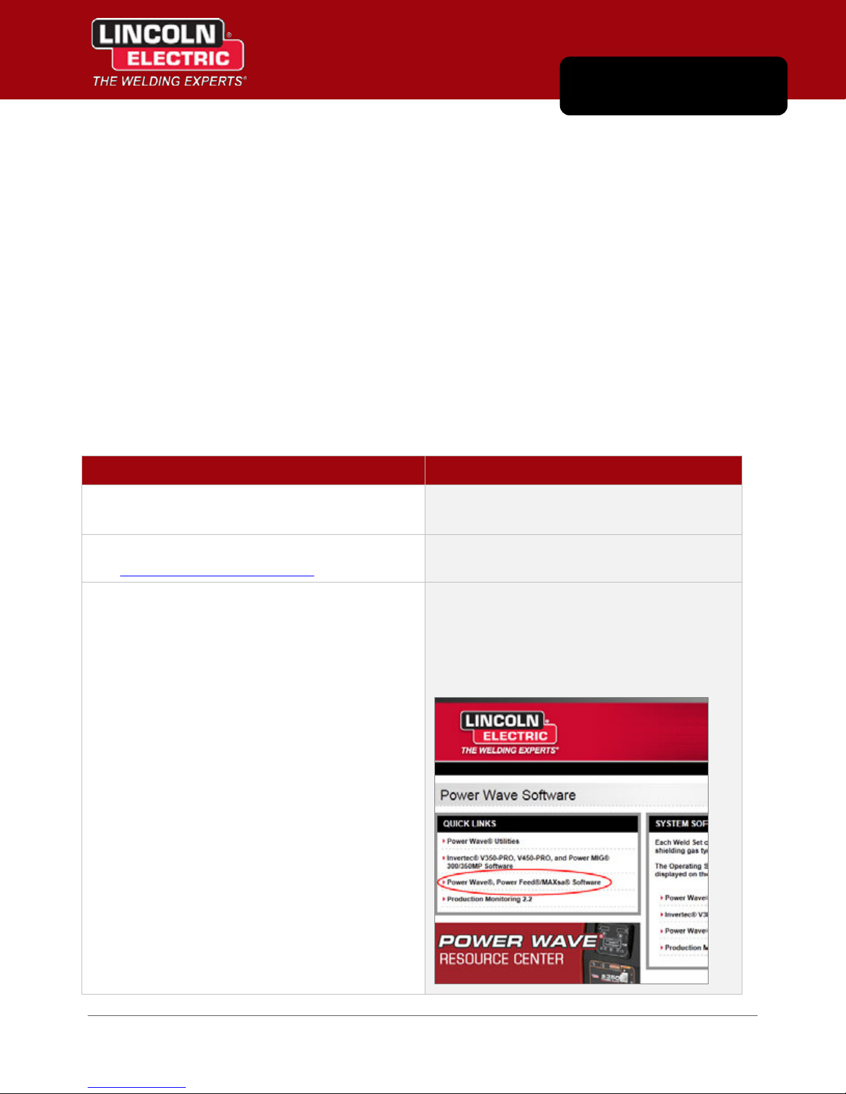
4. In the Quick Links section, click the Power
Wave®, Power Feed®/MAXsa® Software link.
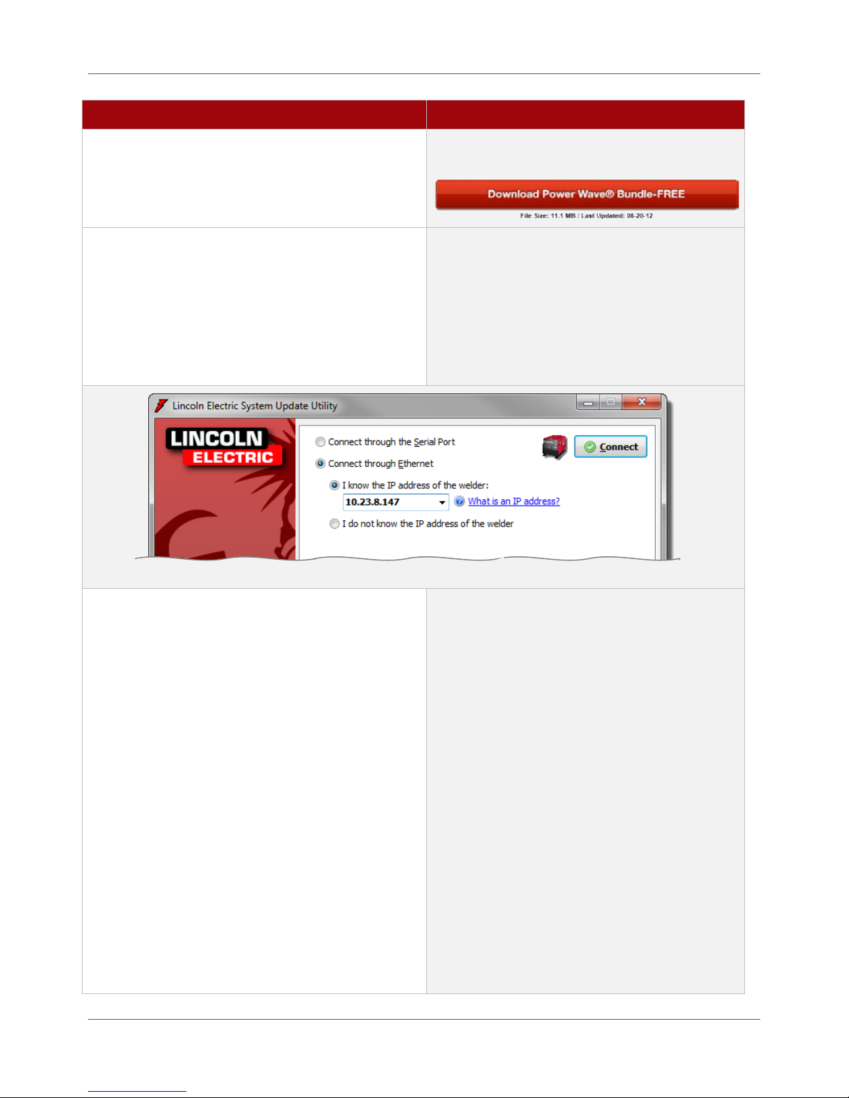
5. Click the Download Power Wave® Bundle-FREE
button to run the update.
The system displays a page containing the
Download Power Wave® Bundle-FREE button.
NOTE | Depending on your Windows version,
you may have to click Run or Allow to permit
your system to launch the file.
The system opens the Lincoln Electric System
Update Utility window where you tell the utility
how to find the Welding Power Source you want
to update.
6. Choose the Connect through Ethernet option
and enter the IP address of the Welding Power
Source you want to update.
TIP | If there is an IP address already
displayed, it is the IP address of the last
Welding Power Source that was connected.
Be sure you enter the correct address for the
current Welding Power Source you want to
update.
You can enter the IP address for the Welding
Power Source in one of two ways:
Type the specific IP address into the I
know the IP address of the welder field.
Choosing the I do not know the IP
address of the welder option. The
update utility scans your network and
displays a list of Welding Power Source
IP addresses on the same subnet.
NOTE | If this Welding Power Source has
older firmware, the IP address will not show up
using this method.
3.2 Power Wave® Manager User Manual IM8002
Page 21
Update Welding Power Source Firmware Chapter 3. Installing Power Wave® Manager
the Troubleshooting section (Appendix A).
Procedure Details
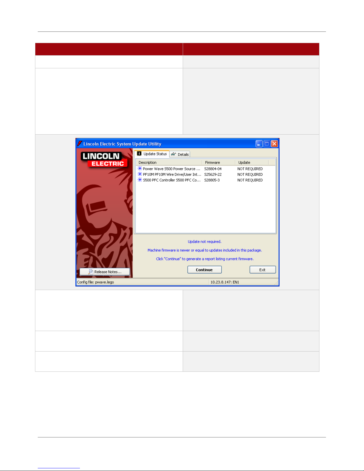
7. Click the Connect button once you have
entered the IP address for the power source
you are updating.
The software scans the Welding Power Source to
verify if the firmware currently on the machine
is up to date.
TIP | You can also see this information under
System Status > Module Information > Software
Version in Power Wave® Manager. See Figure
5.4 on page 5.4.
8. If the firmware is not up to date, you must click
Continue to update the Welding Power Source.
9. Exit the program once the firmware has
finished updating.
10. Repeat steps 4 through 9 for each power source
you need to update.
IM8002 Power Wave® Manager User Manual 3.3
The system proceeds with the update.
If the firmware is already up to date, you will
receive the message Update not required and
you can click Exit to close the window.
Page 22

Chapter 3. Installing Power Wave® Manager Installing Power Wave® Manager
Installing Power Wave® Manager
Once you update the Welding Power Source(s), you need to upgrade to the latest version of Power Wave®
Manager. If installing Power Wave® Manager for the first time, these instructions are also for you. Power
Wave® Manager is a software application that allows you to manage a multitude of settings and
configuration options within the Lincoln Electric Power Wave® family of Welding Power Sources. It also
provides in-depth diagnostics of the Welding Power Source’s hardware and firmware to help identify and
eliminate issues with welding or configuration.
TIP | If you already have Power Wave® Manager installed, you
can simply open the software. Depending on your version
of the software, the system automatically checks for and
installs any updates. If it doesn’t do this automatically, you
can click the Check for Updates button. If the software
updates, you can skip ahead to the next section.
Procedure Details
1. Log in to the computer as a user with
administrative privileges.
2. Open your browser and go to
www.powerwavesoftware.com
.
3. Enter your username and password in the
Email and Password fields and click Sign In.
Contact your IT department if you do not have
administrator privileges.
The Login page displays.
These are the same credentials you used when
updating the Welding Power Source firmware.
Once you log in, the system displays the Power
Wave Resource Center.
4. In the Quick Links section, click the Power
Wave® Utilities link.
3.4 Power Wave® Manager User Manual IM8002
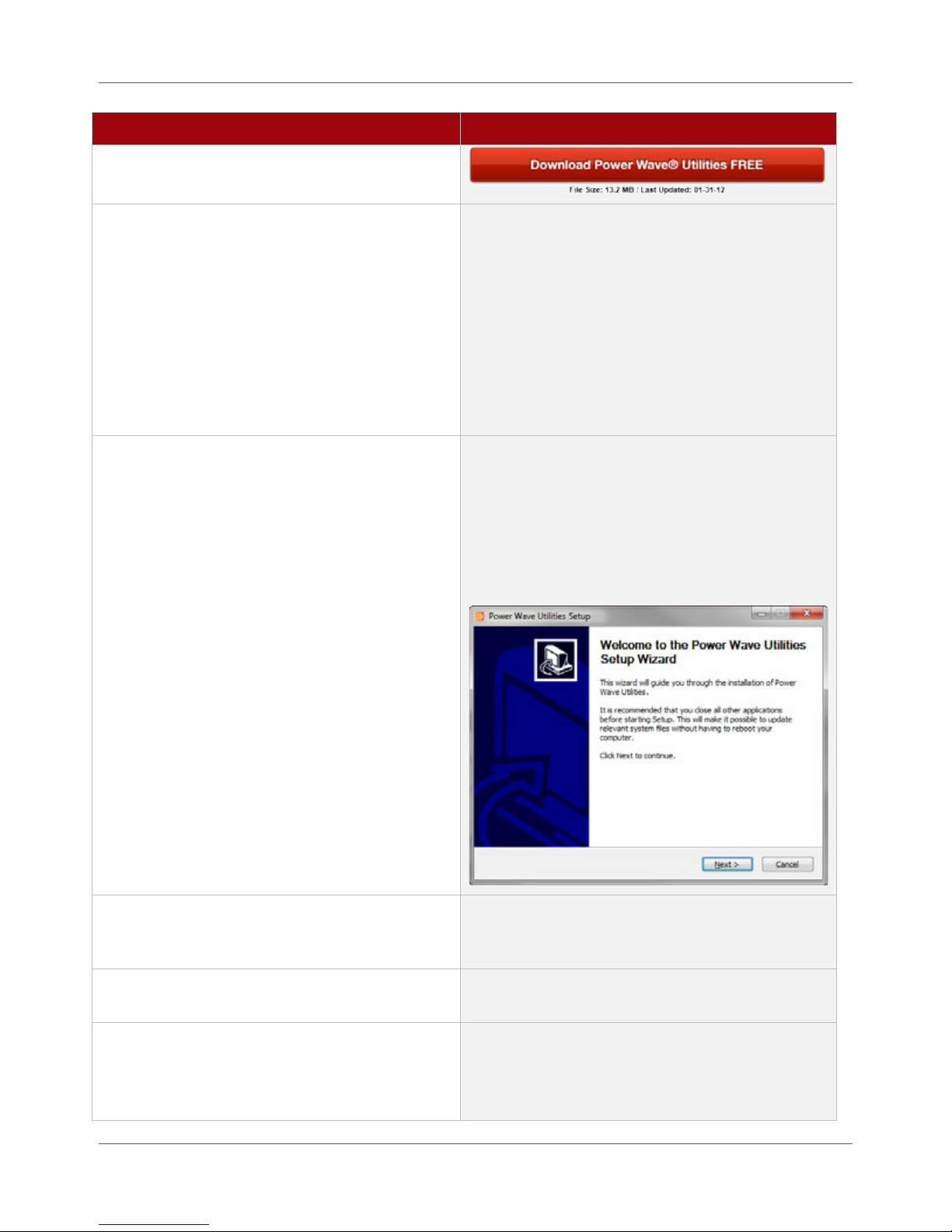
The system displays a page containing the
Download Power Wave® Utilities FREE button.
Page 23
Installing Power Wave® Manager Chapter 3. Installing Power Wave® Manager
Procedure Details
5. Click the Download Power Wave® Utilities
FREE button to run the update.
6. Select your language from the drop-down
and click OK.
NOTE | Depending on your Windows version,
you may have to click Run or Allow to permit your
system to launch the file.
TIP | If you haven’t logged in as a user with
administrative privileges, you may have to
download the file, open the location where you
downloaded it, right-click the file and select Run
as administrator.
The system displays the Installer Language dialog.
If you are running an older version of Power Wave®
Manager, the system prompts you to remove the
old version. Click OK to allow the installer to
remove the old version.
If this is a new installation (or once the old version
is removed), the system displays the installation
welcome window.
7. Click Next on the Welcome screen to move to
the License Agreement and continue the
installation.
8. You must accept the License Agreement and
click Next to continue.
9. Leave the default value in the Destination
Folder field and click Install.
IM8002 Power Wave® Manager User Manual 3.5
The system extracts files and installs the Power
Wave® Utilities on your computer. Once it is
complete, the final page of the Setup Wizard
opens.
Page 24

Chapter 3. Installing Power Wave® Manager Installing Power Wave® Manager
Procedure Details
10. Click the Finish button to exit the installer.
Congratulations! You have installed Power Wave®
Manager and can now configure your Welding
Power Source.
3.6 Power Wave® Manager User Manual IM8002
Page 25
Chapter 4
Overview of Power Wave® Manager
Power Wave® Manager is a software application that allows you to configure and manage the Power
Wave® family of Welding Power Sources. Once you connect to a Welding Power Source, you have a
multitude of tools at your disposal.
Setting a Preferences Folder
When you first open Power Wave® Manager, the system may prompt you to set a Preferences folder. This
folder houses weld training files and is the backup location used for storing weld logs, backups, SnapShots
and other files. Simply choose a folder on your computer where Power Wave® Manager can store these
files. Your computer must have permissions to access to this folder (whether specific to your user account
or a user group of which your account is a member). If you do not, Power Wave® Manager prompts you
again to select a folder. Check with your local IT department if you need permissions to the folder to which
you want to save files.
Connecting to the Welding Power Source
Once you have physically connected the Welding Power Source to the computer with an Ethernet cable or a
serial cable setup (Chapter 2), you can open Power Wave® Manager and connect to the software within the
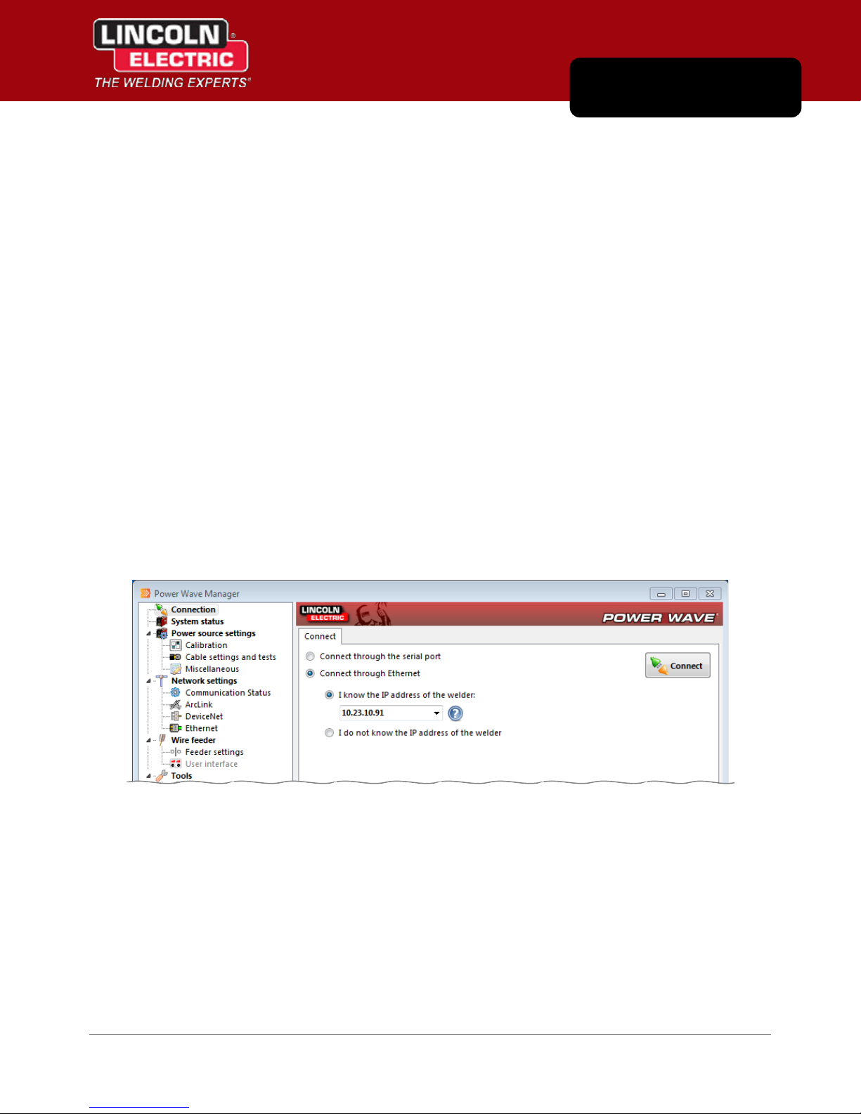
power source. When you first open Power Wave® Manager, the system displays the Connection section
(Figure 4.1). From here you can choose your connection method: Ethernet or a serial connection.
Figure 4.1 Available Connection Methods
IM8002 Power Wave® Manager User Manual 4.1
Page 26
Chapter 4. Overview of Power Wave® Manager Connecting to the Welding Power Source
Ethernet Connection
The preferred method of connecting your computer to the Welding Power Source is through an Ethernet
connection, even if you do not know the specific IP address of the power source. Power Wave® Manager
can help you find it. The steps below walk you through connecting to the power source.
Figure 4.2 Connecting Using an Ethernet Connection
To connect the Power Wave® Manager application to the power source through an Ethernet connection:
Procedure Details
1. Open Power Wave® Manager.
2. Choose the Connect through Ethernet option.
Generally, you can select Start > All Programs >
Lincoln Electric > Power Wave® Manager from the
computer’s main menu.
When Power Wave® Manager opens, it
automatically displays the Connect tab for you
(Figure 4.2).
4.2 Power Wave® Manager User Manual IM8002
Page 27

Connecting to the Welding Power Source Chapter 4. Overview of Power Wave® Manager
Procedure Details
3. Choose I know the IP address of the welder (if
you know the network address) and type the
IP address in the text field.
OR
Choose I don’t know the IP address of the
welder if you need to scan the network to
find the welder’s address. See page 4.3 for
more information on finding the IP address.
4. Click the Connect button.
An IP address is a numeric identifier for a device
on a network, similar to a phone number, and is
composed of four numbers (each ranging from 0
to 255). All devices that participate on the
network must each have a unique IP address.
For example, 10.23.10.90 is a valid IP address.
NOTE | If there is an IP address already
displayed in the text field, it is the IP address of
the last Welding Power Source that was
connected. Be sure you enter the correct address
for the current Welding Power Source you want
to update.
The system attempts to connect to the Welding
Power Source. If the connection is established
successfully, the software automatically displays
the System status section for you (Chapter 5).
If Power Wave® Manager could not connect to the
Welding Power Source, there may be a couple of
solutions you can try. Please refer to Appendix A
for more information.
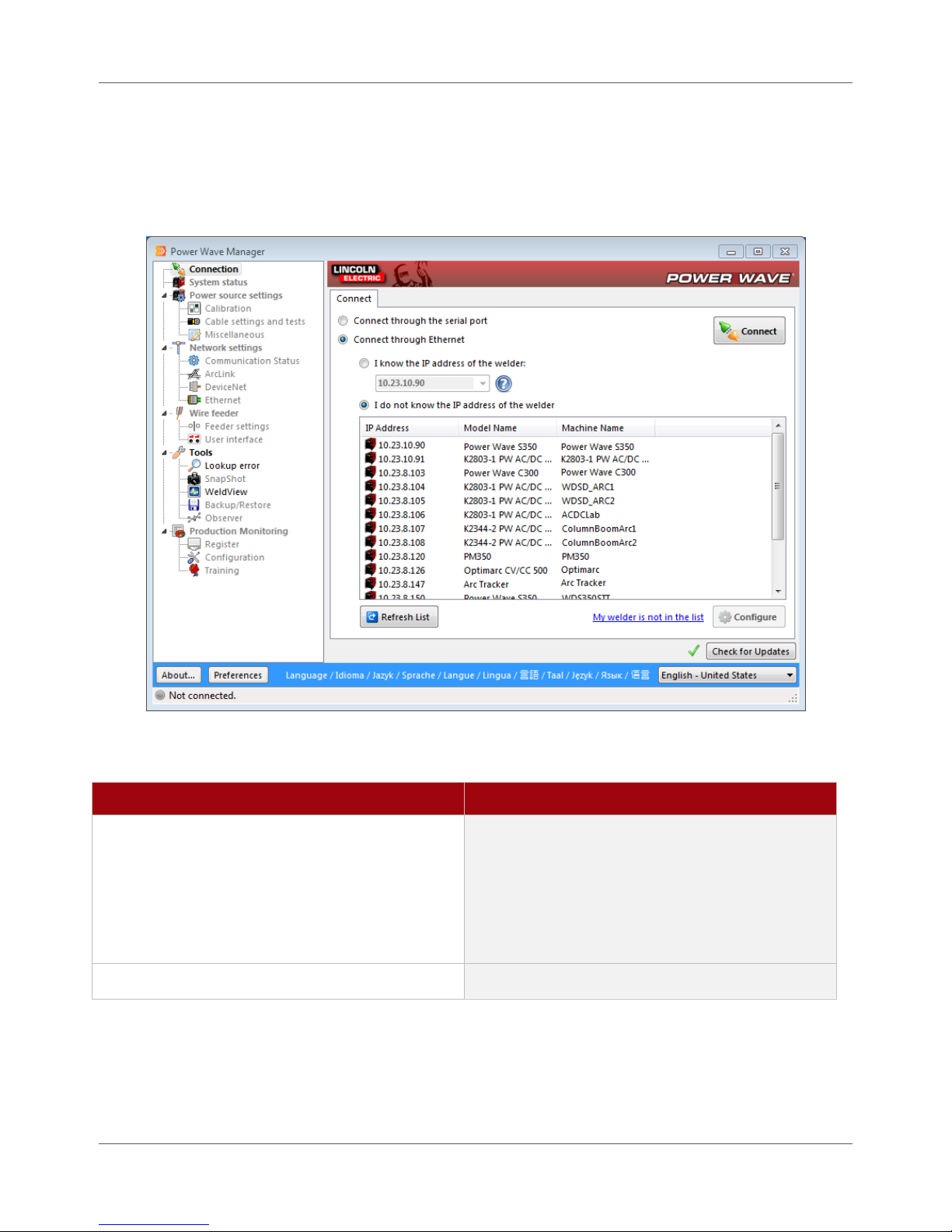
Finding the IP Address of a Welder
If you don’t know the IP address of a Welding Power Source or if you are having trouble connecting when
you enter a specific IP address, you can have Power Wave® Manager scan your network for welders. When
you choose the I do not know the IP address of the welder option on the Connect tab, the system
automatically begins scanning your network for power sources. Once it completes the scan, Power Wave®
Manager displays the results in the list, along with the model name and machine name.
Simply click on each Welding Power Source in the list until you see the green status light on the Welding
Power Source you want start to blink rapidly. Click Connect. See Appendix A for common reasons you may
experience problems connecting to the power source.
NOTE | The Welding Power Source must be on the same subnet as
the Power Wave® Manager application in order to retrieve
the IP address when using this option.
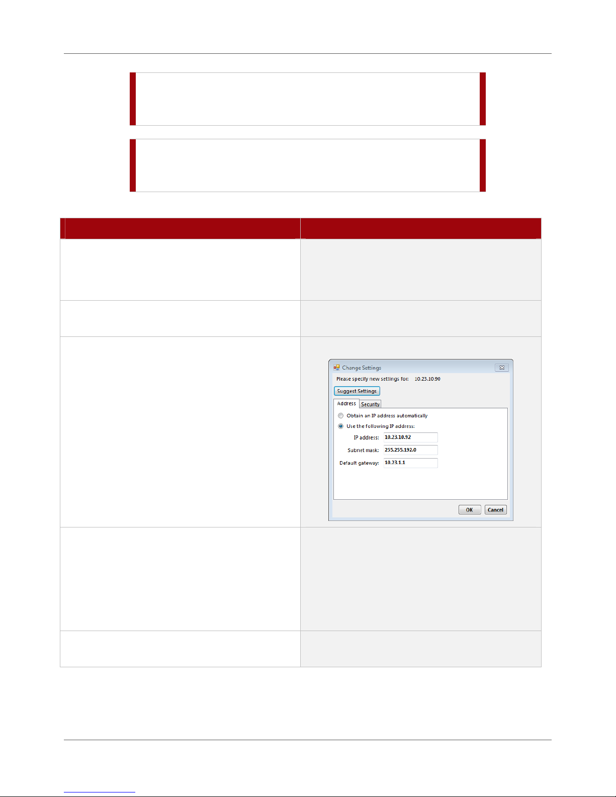
Modifying the Ethernet Settings of a Power Source
In some circumstances, it is necessary to change the Ethernet settings of the Welding Power Source. For
example, you may be moving the Welding Power Source from one location to another on a network, or a
Welding Power Source fails to connect even though it appears in the list.
IM8002 Power Wave® Manager User Manual 4.3
Page 28
Chapter4.OverviewofPowerWave®Manager ConnectingtotheWeldingPowerSource
STOP | WhenyouclicktheOKbutton,theWeldingPowerSource
resetsandstopswelding.Besuretoonlyclickthisbuttonif
thepowersourceisnotcurrentlywelding.
STOP | IftheWeldingPowerSourceiscurrentlypartofanetwork,
contactyournetworkadministratortoverifyyoucanmake
changestotheEthernetsettingsofthepowersource.
Tochangethenetworksettings(includingtheIPaddress)onapowersource:
Procedure Details
1. OntheConnecttabofPowerWave®
Manager,chooseIdonotknowtheIPaddress
ofthewelderandselectthepowersource
fromthelist.
2. VerifytheselectedWeldingPowerSourcehas
ablinkinggreenstatuslight.
3. ClicktheConfigurebutton.
4. Makeyourchanges.
Thishelpsyouensureyouchangethesettingson
theintendedWeldingPowerSource.
TheChangeSettingswindowopens.
Ifyourcomputerisdirectlyconnectedtothe
WeldingPowerSourceusinganEthernetcable,
youmayclicktheSuggestSettingsbutton.This
willautomaticallygeneratethepropernetwork
settingsfortheWeldingPowerSourcethatwould
makeitreadytocommunicatewithyour
computer.
5. ClickOK.
4.4 PowerWave®ManagerUserManual IM8002
TheWeldingPowerSourcethenresetsand
acceptsitsnewnetworksettings.
Page 29
Navigating Power Wave® Manager Chapter 4. Overview of Power Wave® Manager
Serial Connection
Once you have the computer and power source physically connected through a serial cable setup, simply
choose the Connect through the serial port option on the Connect tab of Power Wave® Manager (Figure 4.1
on page 4.1). Follow the onscreen instructions to establish a connection to the power source.
Navigating Power Wave® Manager
When you launch Power Wave® Manager, the navigation tree down the left side allows you to access
configuration options for the power source to which you have connected. Click the menu item in the
navigation tree to display the available options on the right side of the window.
By default, Power Wave® Manager starts up in the Connection section and allows you to connect to a
power source. In order to access the other menu items of Power Wave® Manager (with the exception of
Lookup Error and WeldView), you must connect to a power source.
Figure 4.3 Power Wave® Manager
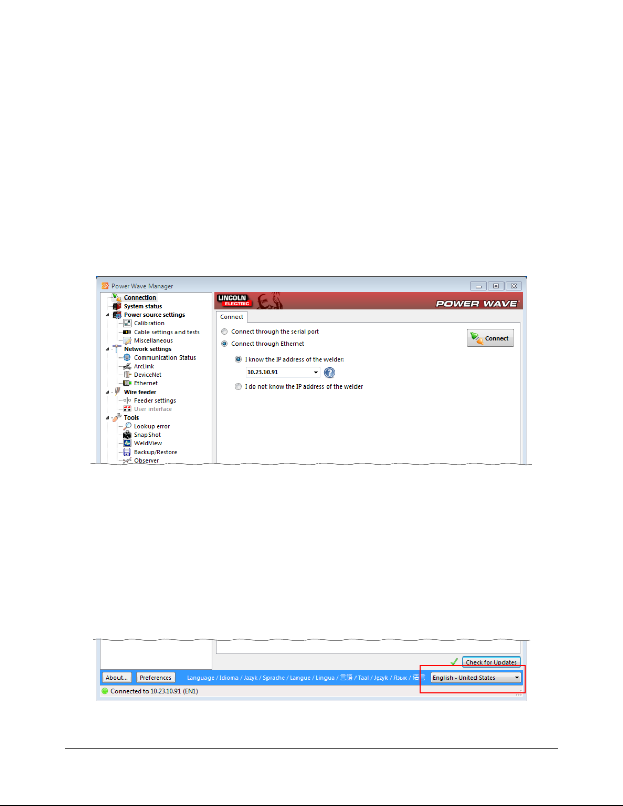
Language Selection
Power Wave® Manager has built-in support for multiple languages. By default, the program automatically
detects the language used by your operating system and switches the language of the interface accordingly.
For example, on a Japanese installation of Windows, Power Wave® Manager automatically switches to
using Japanese text and messages.
If you would like to change the language used by Power Wave® Manager, select the appropriate language
from the Language drop-down (Figure 4.4).
Figure 4.4 Changing the Language of Power Wave® Manager
IM8002 Power Wave® Manager User Manual 4.5
Page 30

Chapter 4. Overview of Power Wave® Manager Language Selection
THIS PAGE INTENTIONALLY LEFT BLANK.
4.6 Power Wave® Manager User Manual IM8002
Page 31
Chapter 5
System Status
When Power Wave® Manager first establishes a connection to the Welding Power Source, it switches to the
System status section and provides you with in-depth information about the Welding Power Source. With
the System status section, you can review each component of the Welding Power Source, review a module
if there is a problem and create a SnapShot file for troubleshooting.
Figure 5.1 System Status
Tool Bar
At the top of the System status section (Figure 5.1), there is an action bar that allows you to change your
display, clear the history and save a SnapShot of the current activity on the power source.
Refresh button: This button allows you to rescan the Welding Power Source for problems. The
most recent results are displayed on the System status tab.
Display drop-down: The Display drop down allows you to switch between Diagnostics (page 5.2)
and Detailed Status (page 5.3).
Clear logs button: This button deletes the Event and Fatal Event log histories in all modules of
the Welding Power Source. The system records the date and time the logs were cleared and
displays this information under the appropriate component.
STOP | When you click the Clear logs button, the Welding Power
Source resets and stops welding. Be sure the power source
is not currently welding.
TIP | When you click the Clear logs button, Power Wave®
Manager uses the date and time of the local host computer,
rather than the date and time on the selected Welding
Power Source.
SnapShot button: This button allows you to save a file that contains detailed configuration and
debugging information collected from each module in the Welding Power Source. This can help
Lincoln Electric Support to troubleshoot any possible issues that cannot be easily resolved. See
page 9.2 for more details.
IM8002 Power Wave® Manager User Manual 5.1
Page 32
Chapter 5. System Status System Status Tab
System Status Tab
The System status tab displays any problems that may be present in any of the components of the Welding
Power Source, including hardware, firmware and software (e.g., DeviceNet module, wire drives, or user
interfaces).
Figure 5.2 System Status Tab
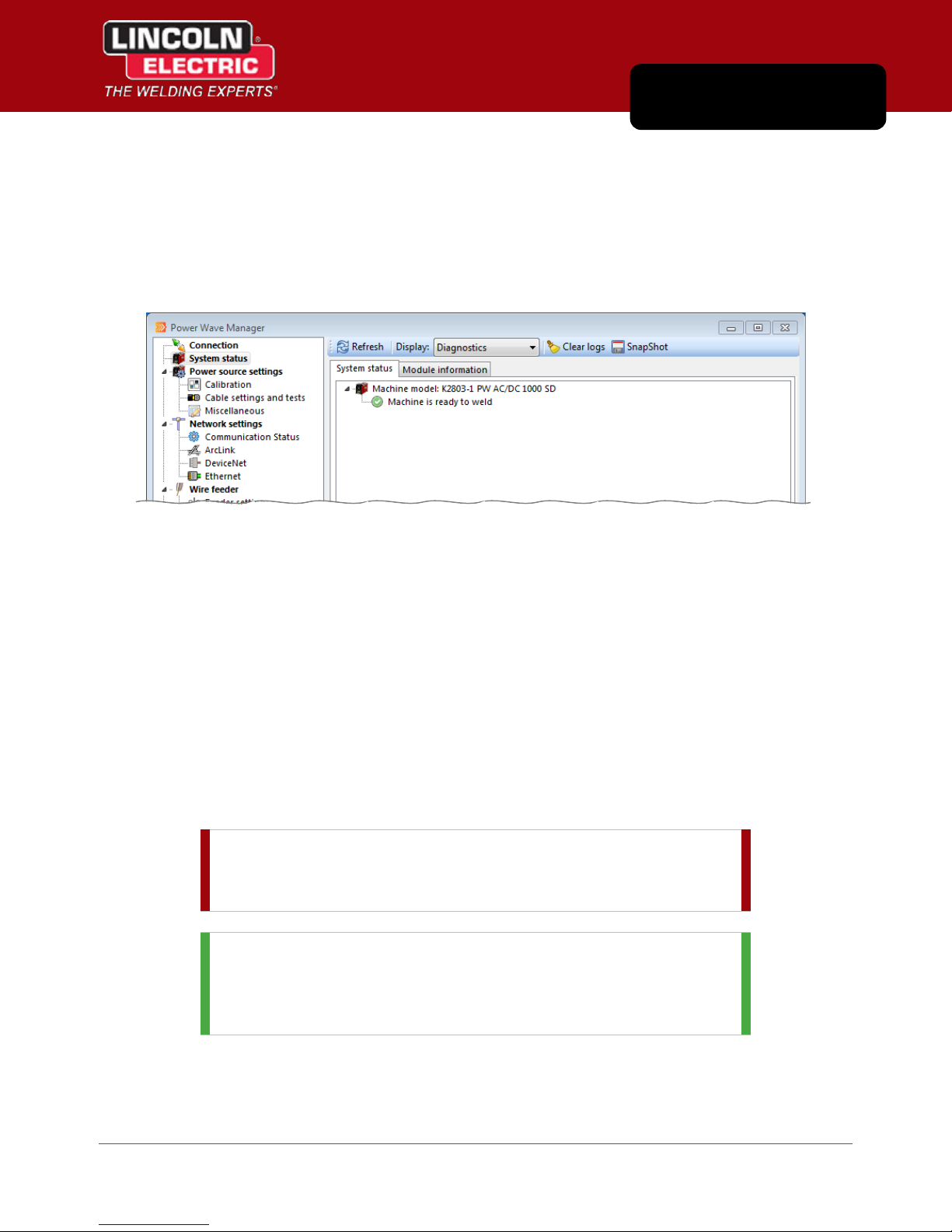
Diagnostic Display
Power Wave® Manager automatically runs a diagnostic on the Welding Power Source when you connect to
a power source and displays the System status section for you when the connection is successful. If there
are no problems with the Welding Power Source, the Ready icon ( ) displays and indicates that the
machine is ready to weld (Figure 5.1 on page 5.1).
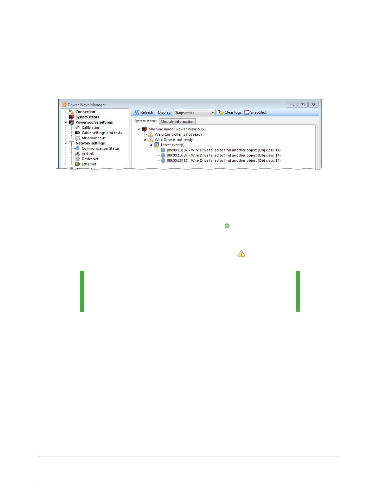
If the program detects an event or a malfunction in the Welding Power Source, it will attempt to determine
which component caused the malfunction and displays the Error icon ( ), along with any error codes or
log entries to help you correct the problem.
TIP | To retrieve more information about a certain error code,
refer to the Lookup error section on page 9.1. You can also
double-click the icon next to the error, and the system
automatically takes you to the Lookup error section.
Each event has a time stamp and a description. For modules that have a real-time clock, such as a robot or
Ethernet module, the time stamp will indicate the time of the event. Otherwise, the time stamp indicates
the amount of time that passed since the Welding Power Source powered up before the power source
experienced the error.
For example, in Figure 5.2, the Weld Operator powered up the power source and 13 seconds later, the
event occurred.
5.2 Power Wave® Manager User Manual IM8002
Page 33

System Status Tab Chapter 5. System Status
Detailed Status Display
If you see error icons and need to look into the problems further, you can select Detailed status from the
Display drop-down and view additional information for each component connected to the Welding Power
Source. In Figure 5.3, all components are ready to weld, except two (the Weld Controller and the User
Interface). Click the arrow ( ) in front of each component to review the details if there are any available.
Figure 5.3 Detailed Status
There are two types of error logs: a Fatal Error Log and an Event Log. These are historical histories for the
component and could include log entries from a previous issue. When you expand the component
displaying the Error icon ( ), Power Wave® Manager displays the number and description of the error or
event (Figure 5.3). These log entries can provide additional information to help you find the cause of any
problems.
NOTE | An event does not always indicate a malfunction. An event
can be posted as an informational entry. Even components
that are ready to weld may have events recorded in their
log.
IM8002 Power Wave® Manager User Manual 5.3
Page 34

Chapter 5. System Status Module Information Tab
Module Information Tab
The Module information tab displays information about each hardware module attached to the Welding
Power Source. This information includes versions of the hardware and firmware of each module, serial
numbers, Weld Set name, and miscellaneous information such as firmware revision numbers and
checksums. You can switch between different sub-tabs to view information about the corresponding
hardware module.
TIP | The Software Version is important to know when updating
the firmware on the Welding Power Source. See step 7 on
page 3.3.
Figure 5.4 Module Information Tab
5.4 Power Wave® Manager User Manual IM8002
Page 35

Chapter 6
Power Source Settings
The Power source settings section consists of various subsections that contain settings for the Welding
Power Source component of the welding system. You will access the Power Source Settings when you first
set up your Welding Power Source, but once you have your Welding Power Sources set up and welding, you
will use this section infrequently. You may need to recalibrate the machine over time or as processes
change.
Calibration
The Calibration section allows you to calibrate the Welding Power Source by adjusting the amperage and
voltage outputs so that they match setpoint values. You can also use this function to activate the Welding
Power Source output for other troubleshooting purposes. To change the amperage setpoint, you can click
the up or down arrows ( ) next to the Amperage setpoint field or type the specific value directly in the
field.
STOP | Buttons on this tab control the output of the
Welding Power Source. Be sure to exercise all
appropriate safety procedures when
performing actions on this tab. Be careful that
the Welding Power Source is not currently
welding before calibrating.
IM8002 Power Wave® Manager User Manual 6.1
Figure 6.1 Calibration
Page 36

Chapter 6. Power Source Settings Calibration
The following is the recommended procedure for calibrating your power source:
Procedure Details
1. Attach Welding Power Source output cables
to a 300A/30V resistive grid load.
2. Open Power Wave® Manager.
3. Connect to the power source.
4. Display the Calibration section.
5. Click the Turn output ON button.
6. Use the plus and minus icons ( and ) to
the right of Amperage adjust (Figure 6.1) to
calibrate the Welding Power Source to the
value you set in Power Wave® Manager.
7. Use the plus and minus icons ( and ) to
the right of Voltage adjust (Figure 6.1) to
calibrate Power Wave® Manager to the
Welding Power Source.
The Turn Output ON button enables the output
of the Welding Power Source. When you turn
the output on, the indicator will begin to flash red
( ), and values will appear under Feedback for:
Output amperage, Output voltage, Capacitor
voltages and Voltage sense location.
This adjusts the actual measured values on the
Welding Power Source to match Power Wave®
Manager.
This adjusts the feedback in Power Wave®
Manager to match the Welding Power Source.
STOP | Do not calibrate voltage at voltages
greater than 50V.
8. Click the Turn output OFF button.
The Turn Output OFF button disables the Welding
Power Source’s output.
6.2 Power Wave® Manager User Manual IM8002
Page 37

Cable Settings and Tests Chapter 6. Power Source Settings
Cable Settings and Tests
The Cable settings and tests section allows you to configure and test your welding cables and sense leads
for the Welding Power Source to which you are connected.
Sense Lead Settings Tab
Use these settings to enable or disable automatic hardware sense lead selection or to modify the behavior
through manual settings. For most applications, the Automatic hardware sense lead selection is the best
method to use. This method reduces the chance of fairing and losing tips due to sense lead losses.
NOTE | The Sense lead settings tab is only available for those
Welding Power Sources that do not have DIP switches for
modifying the sense lead location. The settings are also not
available for Welding Power Sources that do not support
changing the sense lead selection.
Figure 6.2 Sense Lead Settings Tab
Enabling Work Sense Lead
You can configure the system to force sense arc voltage from the work sense lead (21 lead) instead of
the negative output stud. This requires connecting to the voltage sense connector and attaching the
work lead to the work.
To enable the work sense lead:
Procedure Details
1. Remove the check mark from the Automatic
hardware sense lead selection checkbox.
2. Place a check mark in the Enable remote
voltage sense leads checkbox.
3. Click the Apply settings button.
IM8002 Power Wave® Manager User Manual 6.3
Page 38

Chapter 6. Power Source Settings Cable Settings and Tests
Enable Negative Welding Polarity
If negative welding polarity is required for the Welding Power Source, such as in some Innershield™
applications, you may need to configure the correct voltage sense location manually.
NOTE | If the system is already configured to sense arc voltage at
the remote voltage sense leads, no changes are required.
To enable negative welding polarity:
Procedure Details
1. Remove the check mark from the Automatic
hardware sense lead selection checkbox.
2. Place a check mark in the Force negative
weld polarity checkbox.
3. Click the Apply settings button
NOTE | If the sense lead selection is specified
for a welding procedure, that selection will have
precedence over the settings you set here.
Therefore, some welding processes, such as TIG
(GTAW), stick (MMAW), and SMAW, will override
the Power Wave® Manager settings.
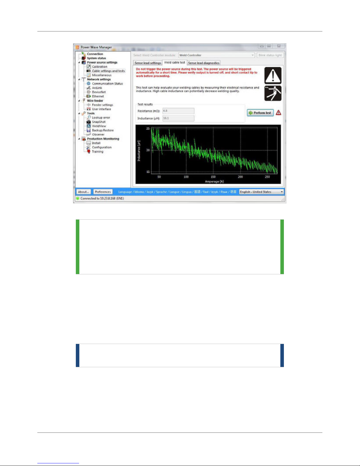
Weld Cable Test Tab
The Weld cable test tab (Figure 6.3) allows you to measure the resistance and the inductance of your
welding circuit. This can be used to determine how setup changes affect the welding circuit. In order to
run this test, the contact tip must be shorted to the work piece.
STOP | Do not trigger the power source during this test.
The power source will be triggered for a short
time. Please verify output is turned off, and
short contact tip to work before proceeding.
Click the Perform test button to begin the inductance and resistance test.
STOP | When you perform this test, the Welding Power Source’s
output will be turned on for a very short time (100
milliseconds).
Once the test is complete, Power Wave® Manager displays the values that were calculated based on the
downloaded weld trace. The resistance value appears in the Resistance field (measured in milliohms) and
the inductance value appears in the Inductance field (measured in microhenries) (Figure 6.3).
6.4 Power Wave® Manager User Manual IM8002
Page 39
Cable Settings and Tests Chapter 6. Power Source Settings
Figure 6.3 Weld Cable Test Tab
TIP | It is good practice to record the results of these tests when
the welding system is operating well. You can then use
those values to compare to values taken when there are
welding problems on the same weld cell. This may help
isolate the problem when the old and new numbers are
significantly different.
Sense Lead Diagnostics Tab
The Sense lead diagnostics tab helps you troubleshoot arc starting problems or erratic arc behavior by
testing and changing the location of the sense lead temporarily. Over time, the constant movement of
equipment, such as robot motion, can cause arc voltage sense leads to detach. The settings on this tab
allow you to test and verify the connectivity and reliability of the voltage sense selection currently set. This
is done by a process of testing voltage sense starting at the studs, then incrementally moving to the remote
voltage sense locations.
NOTE | Any changes made in this tab are temporary and are reset
when the power to the Welding Power Source is turned off.
IM8002 Power Wave® Manager User Manual 6.5
Page 40

Chapter 6. Power Source Settings Cable Settings and Tests
Figure 6.4 Sense Lead Diagnostics
NOTE | You cannot perform this test with ServoTorch.
Automatic Test
Power Wave® Manager can also help you troubleshoot sense lead issues. The software automatically
attempts to detect the sense lead location by turning on the Welding Power Source’s output in an
open circuit voltage (OCV) mode and reading back voltage. The system does this while stepping
through the various manual sense lead locations, determining which location is most likely the one
being used.
STOP | Make sure your welding circuit is open before performing
this test.
To perform the automatic test, choose the Detect sense lead location automatically option in Power
Wave® Manager and click the Test sense lead selection button.
6.6 Power Wave® Manager User Manual IM8002
Page 41
Miscellaneous Chapter 6. Power Source Settings
Manual Test
If you know want to step through each sense lead manually, you can use Power Wave® Manager to
test them individually and force the Welding Power Source to sense voltage from the location you
choose.
To perform the test, choose the Select sense lead location manually option and choose one of the
following options. Click the Apply settings button to confirm your choice and click the Test sense lead
selection button to perform the test. Repeat for each option you want to test.
Output studs: This configuration utilizes arc voltage sensing from inside the Welding Power
Source and does not require polarity to be configured.
67 Positive or 67 Negative: Choose the option depending on the welding polarity in which your
system is configured to operate.
67 and 21: Use this option to test both remote voltage sense leads.
STOP | When you have completed testing, cycle the power to the
Welding Power Source (off then back on) to clear any
changes made to the voltage sense location. Be careful that
no welding is currently in progress.
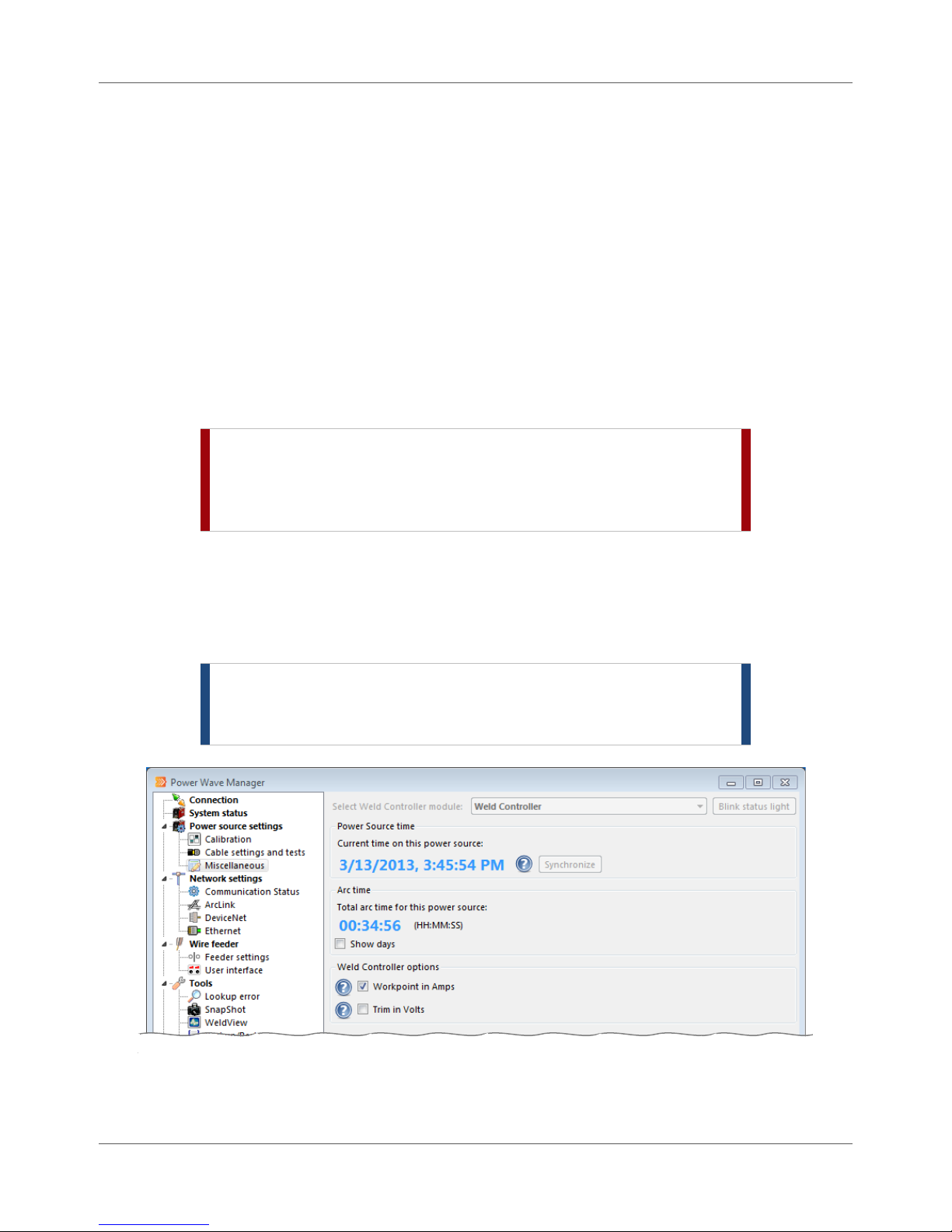
Miscellaneous
In the Miscellaneous section under Power source settings, you can synchronize the date and time on the
power source. You can also see the lifetime arc time for the power source. You can also set a couple of
options for the selected weld controller.
NOTE | Anytime you make changes to the options in this section,
be sure you click the Apply settings button to commit your
changes.
IM8002 Power Wave® Manager User Manual 6.7
Figure 6.5 Miscellaneous Section
Page 42

Chapter 6. Power Source Settings Miscellaneous
Time Settings on the Power Source
The Power Source time section displays the current time on the Welding Power Source’s internal clock. The
power source uses this when recording internal events, errors, and information that it sends to Production
Monitoring™ and CheckPoint™.
NOTE | The Production Monitoring™ and CheckPoint™ application,
if present, periodically sets the clock on the Welding Power
Source to match the time of the Production Monitoring™
server or the CheckPoint™ data center, whichever is
applicable.
If the time shown on the Welding Power Source does not match the time on your local computer, you can
manually synchronize the clocks. Simply click the Synchronize button and the software changes the time
on the Welding Power Source to match the time on your computer.
NOTE | The Synchronize button is not available when CheckPoint™
is enabled. The power source updates the time
automatically from the CheckPoint™ data center.
Total Welding Lifetime
The Arc time section displays the total amount of time that the Welding Power Source has generated an arc
over its lifetime. The time appears in HH:MM:SS format (hours, minutes, and seconds). If the number of
hours is greater than 23, place a check mark in the Show days checkbox to convert the hours into days and
display the result.
Weld Controller
If the Welding Power Source supports the following features, you can use the Weld Controller section to set
a couple of control options:
Workpoint in Amps: Use this option to base the output level on Amps instead of wire feed
speed.
Trim in Volts: You can use this to set the output level based on voltage instead of a unitless
control.
STOP | If you make changes to the Weld Controller and click Apply
settings button, the Welding Power Source automatically
resets. Be careful that no welding is currently in progress.
6.8 Power Wave® Manager User Manual IM8002
Page 43
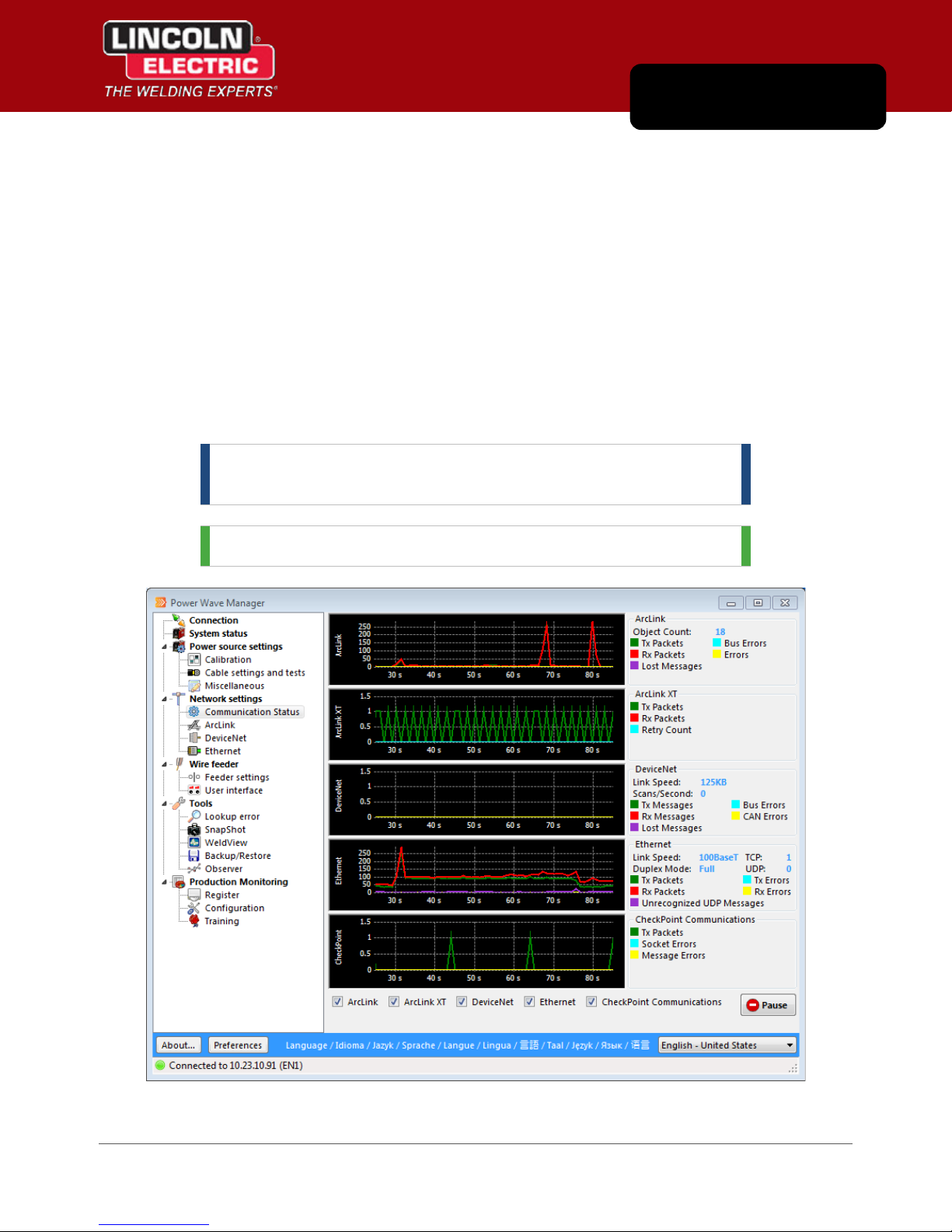
Chapter 7
Network Settings
The Network settings section provides you with the flexibility to configure the connection of the Welding
Power Source to other equipment. You can connect various components through the use of ArcLink
technology, DeviceNet communications, and/or Ethernet connections. The Network settings section allows
you to review and monitor these settings.
Communication Status
Under Communication status, Power Wave® Manager displays an active graph and provides you with the
real-time communication status of the various components connected to this Welding Power Source. This
section is useful for identifying problems or errors in communication. Use the checkboxes at the bottom of
the graphs to add or remove graphs from your displays.
NOTE | The graphs displayed for you depend on the hardware
connected to and supported by the Welding Power Source.
TIP | “Tx” means “transmitted” and “Rx” means “received”.
IM8002 Power Wave® Manager User Manual 7.1
Figure 7.1 Connection Status
Page 44

Chapter 7. Network Settings ArcLink
ArcLink
The ArcLink section provides you with an overview of all the welding system components connected to this
Welding Power Source using the ArcLink technology. This section of Power Wave® Manager also provides
you with the opportunity to “pair” devices together if they haven’t automatically paired themselves. (See
page 7.3 for more on pairing.)
Mapping Status Tab
The Mapping status tab provides you with the logical layout (or “mapping”) of the components connected
to the power source with an ArcLink connection. The display shows the current mapping of the system and
the serial numbers of the components.
TIP | If you have recently connected a new component to the
power source, click the Refresh button to display the most
up to date ArcLink connection information.
If you click on a component, the system displays the available history for that specific component at the
bottom of the window. You can see how many times the unit has powered up, how many times it was
reset, and several other pieces of information.
7.2 Power Wave® Manager User Manual IM8002
Figure 7.2 Mapping Status
Page 45

ArcLink Chapter 7. Network Settings
Pairing Setup
Certain Lincoln Electric components can be “paired” together, such as dual-head wire feeders and user
interfaces. The system usually pairs these automatically for you. However, if there was a problem with
pairing between two or more components, Power Wave® Manager displays the Pairing setup tab (Figure
7.3).
NOTE | If automatic pairing was successful, you will not see the
Pairing setup tab.
Figure 7.3 Pairing Setup Tab
Each module that requires one or more other modules to be paired with it will be shown in the list on the
left, with “slots” that can be filled by modules from the list on the right.
To pair two modules together:
Procedure Details
1. Click an unused slot under the module you
want to pair with another.
2. Click the module on the right and drag it over
to the left and drop it over the unused slot.
3. Click the Apply settings button.
Power Wave® Manager displays any other
modules on the right side that are available for you
to pair it with.
You can also click the arrow buttons between the
two panes to move the modules back and forth.
IM8002 Power Wave® Manager User Manual 7.3
Page 46

Chapter 7. Network Settings DeviceNet
DeviceNet
The DeviceNet section allows the setup and verification of the DeviceNet connections of various modules to
the Welding Power Source.
NOTE | Modifying DeviceNet settings is highly technical. If you are
uncomfortable with making changes, contact your local IT
support for assistance. You should also consult the
appropriate Lincoln Electric Operator Manual for the
module you have installed.
Multiple DeviceNet Modules
If the system to which a Welding Power Source is connected contains more than one DeviceNet module
(e.g., a Power Wave® connected to a robot teach pendant), you can select the module you want to review
from the drop-down list. This allows you to configure settings for each module.
Figure 7.4 Multiple DeviceNet Module Drop-down
If you’re not sure the selection in the drop-down refers to the actual DeviceNet module you want to review,
click the Blink status light button. This causes the green light on the selected machine to start blinking
rapidly so you can visually identify the module.
Status Tab
The Status tab displays basic information about the DeviceNet interface on the Welding Power Source, as
well as any errors currently present on the interface. Remember: You can select each module connected
using DeviceNet from the Select DeviceNet module drop-down at the top of the window to see information
about that specific module.
7.4 Power Wave® Manager User Manual IM8002
Figure 7.5 Status Tab
Page 47

DeviceNet Chapter 7. Network Settings
For other Welding Power Sources that do not have a DIP Switch, you must use
Configuration Tab
Use the Configuration tab to review and/or edit options for the DeviceNet interface connected to this
Welding Power Source. Power Wave® Manager reads these options from the connected Welding Power
Source and displays them here. The available fields depend on the DeviceNet module. Table 7.1 explains
each of the fields in more detail.
NOTE | For more information on setting up the DeviceNet interface,
refer to the DeviceNet Interface Specification Document
(Y50031) included with the Power Wave® Utilities
installation.
Figure 7.6 Configuration Tab
Table 7.1 Fields on the Configuration Tab
Field Description
System Control
MAC ID This field displays the current media access control (MAC) ID of the DeviceNet
interface installed on this Welding Power Source.
For the following power sources, the MAC ID is usually set by a DIP switch
located on the gateway board, but you can also set the MAC ID from Power
Wave® Manager: PW455, PW455M, ACDC1000, PW655, and Welding Power
Sources that use the K2436-1 Ethernet/DeviceNet Communication Interface.
IM8002 Power Wave® Manager User Manual 7.5
Page 48

Chapter 7. Network Settings DeviceNet
Power Wave® Manager to set the MAC ID of the DeviceNet interface.
Field Description
STOP | If you change the MAC ID, you must cycle the power to the Welding
Power Source (off then back on) in order for the change to take effect. Be
careful not to cycle the power while the power source is currently welding.
Baud Rate
This field displays the current baud rate configured in the DeviceNet interface
installed on this Welding Power Source.
For the following power sources, the Baud Rate is usually set by a DIP switch
located on the gateway board, but you can also set the baud rate from Power
Wave® Manager: PW455, PW455M, ACDC1000, PW655, and Welding Power
Sources that use the K2436-1 Ethernet/DeviceNet Communication Interface.
For other Welding Power Sources that do not have a DIP Switch, you must use
Power Wave® Manager to set the Baud Rate of the DeviceNet interface.
STOP | If you change the Baud Rate, you must cycle the power to the
Welding Power Source (off then back on) in order for the change to take
effect. Be careful not to cycle the power while the power source is currently
welding.
Event Logging The Event Logging checkboxes allow you to control the types of issues that
create a log entry when they occur on this DeviceNet module.
Enable passive mode
operation
Place a check mark in this checkbox when you need to use the DeviceNet
connection only to monitor system operation. When you enable passive mode,
the polled inputs from DeviceNet have no effect on the system except for the
Weld Output disable bit and the Production Monitoring Fault Reset bit.
Restore settings from
memory on reset
DeviceNet will automatically restore weld schedule values on power up that are
not accessible from a polled connection. These include weld mode, strike,
restrike, cold-inch wire feed speeds, and times for preflow, postflow and
burnback.
NOTE | If the system contains a user interface with a memory panel or a
robot/PLC that restores settings on power up, do not check this box.
Fault if no polled
connection detected
This option disables welding if a polled DeviceNet connection is not present.
Place a check mark in this checkbox when a DeviceNet master controls the
machine.
Report Trim/Wave
Outer Process Limits
When you choose to report the Trim/Wave Control input in Engineering units
and these inputs are dependent on the Workpoint, place a check mark in this
checkbox to report back the high and low limits of the Trim and Wave Control
parameters. Typically, this item is checked.
If there is no check mark in this checkbox, the returned limits will be based on
the Workpoint. As the Workpoint changes, the acceptable range for the Trim
and Wave Control change as well, removing the check mark from this box also
reports back that acceptable range.
7.6 Power Wave® Manager User Manual IM8002
Page 49

DeviceNet Chapter 7. Network Settings
Field Description
TAST update
frequency
Meter time constant This parameter sets the filtering of the feedback data. The default value of 400
Analog scans
between updates
Cold-inch wire feed
speed
This parameter is used for Through the Arc Seam Tracking (TAST). The lower
the number the more often the feedback is updated, but higher the system load
on the boards. In general, if TAST is being used, this frequency is set to a value
between 10 and 20. Otherwise, a value of 100 is usually acceptable. This value
is only relevant for the PW455, 455M, 655, 355, and ACDC1000.
is usually used unless TAST is being done. With TAST, this field is usually set to a
value around 75. This value is only relevant for the PW455, 455M, 655, 355,
and ACDC1000.
This determines how often the analog input channels (i.e., workpoint, trim, and
wave control) update the system in terms of polled I/O scans. For example, if
you enter 50, every 50th I/O scan will be accepted.
The setting of this item depends on how often the Welding Power Source is
scanned. For systems with a scan rate of 200 or more, the default is generally
50. For systems with very low scan rates, such as 10 Hz, a setting as low as 2
might be needed.
This parameter sets the feed speed of the wire while cold-inching or jogging the
wire. This value is used for either cold-inching forward (Jog +) or cold-inching
reverse (Jog -). This value is in units of inches per minute (IPM).
Polled I/O Connection
Workpoint input This indicates whether the values passed to the system through the analog
DeviceNet channels for the Workpoint parameter are raw values or scaled
engineering values. For most applications, choose Engineering units.
For example, when the Workpoint is in inches per minute and you choose
Engineering units, a value between 50 and 800 might be expected to be
commanded on the DeviceNet analog input for the Workpoint. This would
represent a value of 50 to 800 inches per minute.
When you choose the Unscaled values option, the commands for Workpoint
range from 0 to 32767, corresponding to the minimum and maximum
Workpoint of the selected Weld Mode.
Trim/Wave
Control input
This indicates whether the values passed to the system through the analog
DeviceNet channels for the Trim and Wave Control parameters are raw values
or scaled engineering values.
For example, when the Trim is in volts and you choose Engineering units, a value
between 75 and 520 might be expected to be commanded on the DeviceNet
analog input for the Trim. This would represent a value of 7.5 to 52.0 volts.
When you choose the Unscaled values option, the commands for Trim and
Wave Control range from -32768 to 32767 with 0 representing a nominal value.
A great majority of applications will require Trim and Wave Control command
values to be set near the nominal value.
IM8002 Power Wave® Manager User Manual 7.7
Page 50

Chapter 7. Network Settings DeviceNet
Field Description
Analog output This setting controls the value that is reported by the power source's third
analog feedback. The options that appear vary depending on the machine. A
great majority of applications will use the default Actual WFS option.
Actual WFS: This option reports the actual wire feed speed of the
feeder through the third analog feedback.
Commanded WFS: Typically used for non-Lincoln Electric wire
feeders, this option sends the recommended wire feed speed
through the third analog feedback.
Wire Drive Motor Current: Mainly for diagnostics, this output sends
the current driving the motor. If the current deviates from the
current expected, this could indicate a problem such as the wire
being stuck or that the machine just isn’t running efficiently.
Basically, non-AC/DC machines use either the Actual WFS option or the Wire
Drive Motor Current option. AC/DC machines use either the Actual WFS option
or the Commanded WFS option. The appropriate options are visible for that
machine.
Analog Input Channels
Analog input
channels
These values indicate the magnitude of change that must occur on the first
three polled I/O analog DeviceNet channels before the Welding Power Source
will respond to the change. In the case of a command value that is sourced
from an A/D whose output may differ slightly, this configuration prevents
unintended parameter changes.
The attribute is not useful for command values whose source is completely
digital and should be set to 0. One exception is when the Welding Power
Source has an Analog Interface module. In this case, set these values to a 30.
Input channels will be ignored if their Active boxes are unchecked in which case
the Welding Power Source will assign default values to the associated
parameters.
Interface Support
Interface support This field only appears for AC/DC 1000 SD machines. It sets how the DeviceNet
interface behaves for the machine. The two available options are Standard and
Legacy AC/DC 1000:
Choose the Standard option to make the DeviceNet interface
operate like a standard MIG interface. The DeviceNet master must
initialize all sequencer state items.
Choose the Legacy AC/DC 1000 option to make the DeviceNet
7.8 Power Wave® Manager User Manual IM8002
interface operate like an AC/DC1000 DeviceNet interface where
certain sequencer state items are fanned out to other states,
duplicating what was done in the older AC/DC1000 DeviceNet
interface.
Page 51

DeviceNet Chapter 7. Network Settings
Monitor Tab
The Monitor tab contains detailed information about the polled input/output data coming to and from the
Welding Power Source’s DeviceNet interface. This is a troubleshooting tool for those customers
implementing a DeviceNet connection to the Welding Power Source. For detailed information about the
data on this tab, refer to the DeviceNet Interface Specification Document (Y50031) included with the Power
Wave® Manager installation. You can find the document under the Start menu of the computer.
Figure 7.7 Monitor Tab
IM8002 Power Wave® Manager User Manual 7.9
Page 52

Chapter 7. Network Settings DeviceNet
Trace Tab
This tab allows you to record the DeviceNet network traffic coming to and from the Welding Power
Source’s DeviceNet interface and create a file you can send to Lincoln Electric support or keep for reference
in the future. This is extremely useful for troubleshooting communication issues.
Figure 7.8 Trace Tab
Simply set your options and click the Start trace button when you’re ready to capture DeviceNet messages.
Click the Stop trace button when you have the information you need. Power Wave® Manager downloads
the recorded messages from the DeviceNet module and displays them in the list, with all relevant fields
decoded. Table 7.2 explains your options in more detail.
NOTE | The Read trace button allows you to transfer the buffered
data from the Welding Power Source into Power Wave®
Manager manually if needed.
TIP | Click the Save trace button to export the data to a file that
you can send to Lincoln Electric Support for troubleshooting
or keep for your own reference in the future.
7.10 Power Wave® Manager User Manual IM8002
Page 53

DeviceNet Chapter 7. Network Settings
Table 7.2 Options on the Trace Tab
Field Description
Trace type This option helps you control how much data you collect with the
trace.
Continuous: Choose this option if you want the trace to keep
recording data until you click the Stop trace button, regardless
how long the trace is.
Stop when buffer full: Choose this option if you want the trace
to stop automatically when the buffer on the power source is
full of data.
Record outgoing packets and
Record incoming packets
The options in these sections allow you fine tune the amount of data
being buffered. Data buffers can only hold so much data. If you
carefully choose the type of messages you want to trace, you can fit
more messages into the trace.
Without restrictions: Choose this option to run the trace wide
open and including all data. This option fills the buffer very
quickly with fewer messages.
Only if data is different from previous: Choose this option to
include only those DeviceNet messages whose ID is different
from the previous message.
Only if ID, data are different from previous: Choose this option
to include only those DeviceNet messages where both the ID
and the data are different from the previous message.
Only if ID AND _____ = _____: Choose this option to include
only specific messages in the trace.
Weld Limits Tab
The Weld limits tab displays a list of all available Weld Modes supported by the Welding Power Source to
which you are currently connected, as well as basic information for each mode.
When you click on a Weld Mode, Power Wave® Manager displays the types of controls associated with it
(e.g., Workpoint, Trim, and Wave Control) and the outer limits of each control. These appear below the list
of Weld Modes (Figure 7.9). You can use this section to verify that the correct Weld Mode information is
being read over the DeviceNet connection.
IM8002 Power Wave® Manager User Manual 7.11
Page 54

Chapter 7. Network Settings DeviceNet
Figure 7.9 Weld Limits Tab
NOTE | Updating the firmware on the Welding Power Source may
cause the limits of some procedures to change.
Weld Sequencer Tab
The Weld sequencer tab contains advanced configuration settings for the Weld Sequencer component of
the system. It presents an array of sequencer-controlled system attributes, grouped by welding state. This
useful diagnostic tool can help you verify that the settings are correct. If you need to modify a system
variable, double-click the appropriate cell. Refer to the DeviceNet documentation provided by Lincoln
Electric for more information.
7.12 Power Wave® Manager User Manual IM8002
Figure 7.10 Weld Sequencer Tab
Page 55
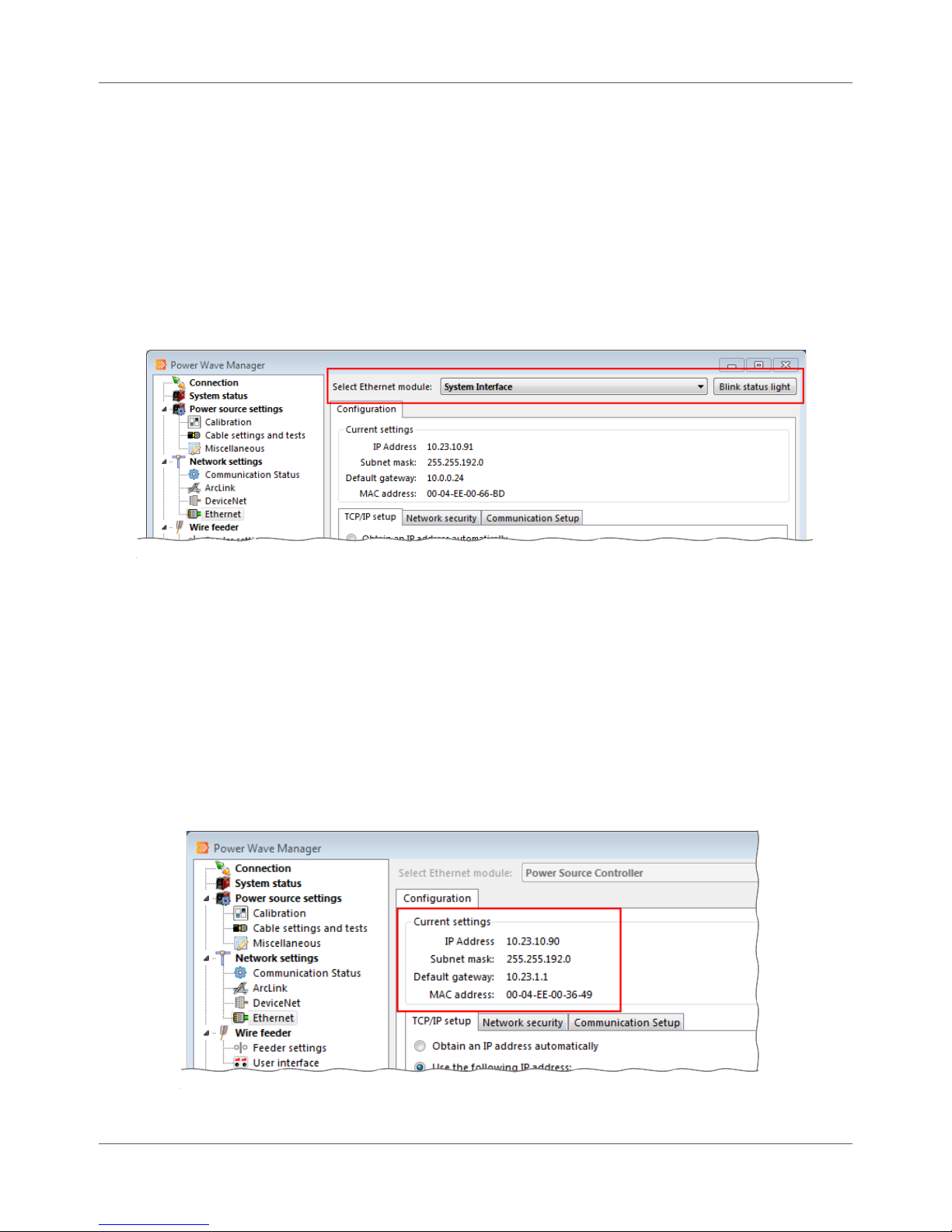
Ethernet Chapter 7. Network Settings
Ethernet
This section provides options for configuring the network settings for the modules connected to the
Welding Power Source through an Ethernet connection.
Multiple Ethernet Modules
If the system to which a Welding Power Source is connected contains more than one Ethernet module (e.g.,
a Power Wave® AC/DC 1000 connected to a System Interface module), you can select the module you want
to review from the drop-down list. This allows you to configure settings for each module connected to the
power source.
Figure 7.11 Multiple Ethernet Module Drop-down
If you’re not sure the selection in the drop-down refers to the actual Ethernet module you want to review,
click the Blink status light button. This causes the status light of the selected module to start blinking
rapidly so you can visually identify the module.
Configuration
The top portion of the Configuration section displays the Welding Power Source’s current network settings,
including IP address, subnet mask and default gateway. (Table 7.3 explains the data under Current settings
in more detail.) The sub-tabs in this section allow you to make modifications to these connection settings,
as well as configure the address of the machines you want to allow access to the Welding Power Source and
adjust the communication speed of the power source over the network.
IM8002 Power Wave® Manager User Manual 7.13
Figure 7.12 Configuration Tab
Page 56

Chapter 7. Network Settings Ethernet
Table 7.3 Fields under Current Settings
Field Description
IP Address This is the location of this Welding Power Source on the computer network. Any
device on your network that wants to communicate with the Welding Power
Source must use the power source’s address to make the connection.
Subnet mask This number is assigned by your local IT department. A subnet is a section of a
computer network. Subnets are used to divide up large networks into small
sections for ease of management, increased performance and increased security.
Default gateway This is the IP address of a router or other device that allows communication with
addresses that are outside your local area network.
MAC address This field displays the current media access control (MAC) ID of the module
selected in the drop-down at the top of the window.
TCP/IP Setup Sub-Tab
On the TCP/IP setup tab, you can configure the IP address of the power source, changing from the
current address to a new IP. Generally, you may need to use Dynamic Host Configuration Protocol
(DHCP) to find an open IP address for initial configuration, for use prior to system integration, or for
mobile or remote welding equipment. Generally, though, you need to use a static IPs, subnets and
gateway addresses assigned by your IT department for most fixed production equipment. A static IP is
required for Production Monitoring™ and CheckPoint™.
STOP | Assigning an incorrect IP address to the Welding Power
Source may cause it to be unreachable on the network.
Figure 7.13 TCP/IP Setup Tab
7.14 Power Wave® Manager User Manual IM8002
Page 57

Ethernet Chapter 7. Network Settings
Simply choose the Obtain an IP address automatically option if you want the Welding Power Source to
assign the IP address automatically using a dynamic IP address.
STOP | If you choose this option, the Welding Power Source
obtains a different IP address every time it connects
to a network.
If you want to assign a specific address to this Welding Power Source, choose the Use the following IP
address option and enter the appropriate information. (Table 7.3 on page 7.14 explains these fields in
more detail.)
Once you have configured the network settings, click the Apply settings button and cycle the power to
the Welding Power Source (off then back on) in order for the new settings to take effect.
NOTE | If you have modified the Welding Power Source’s IP address
and would like to modify more settings, you will need to
connect to the Welding Power Source using the new
address. (See page 4.1 for connecting to a power source.)
TIP | If you cannot connect to the Welding Power Source, refer to
Appendix A for troubleshooting options.
Network Security Sub-Tab
The Network Security tab allows the configuration of a range of IP addresses that are allowed to
connect to the Welding Power Source, as well as another range of addresses that are allowed to
modify parameters on the Welding Power Source (the latter range is a subset of the first). This
provides some control over the components and modules (e.g., controllers, wire feeders, user
interfaces) that can connect to this Welding Power Source.
For each of the two ranges, the user can select either all addresses, addresses only within the
machine’s subnet, or a custom range of addresses.
IM8002 Power Wave® Manager User Manual 7.15
Figure 7.14 Network Security Tab
Page 58

Chapter 7. Network Settings Ethernet
For example, if the custom range is from 192.168.1.0 to 192.168.1.255, a computer whose IP address
is 192.168.1.10 will be able to access this machine, but a computer whose IP address is 192.168.2.1
will not.
Communications Setup Tab
Network speed (how fast your network can transmit data) and the duplex setting (the two-way
communication allowed on that network) dictate how effective the communication is between your
Welding Power Source and the network. The speed and duplex of the Welding Power Source should
match the speed and duplex of your network. Welding Power sources are shipped with default
settings that operate properly with most networks. You typically do not need modify this setting.
Figure 7.15 Communication Setup Tab
You have the following options if you ever need to make adjustments:
100 BaseT, Full Duplex (default)
10 BaseT, Full Duplex
100 BaseT, Half Duplex
10 BaseT, Half Duplex
STOP | Assigning an incorrect network speed and duplex on the
Welding Power Source may cause it to become unreachable
on the network. If you are unsure about what values to
assign to the Welding Power Source, consult your network
administrator.
7.16 Power Wave® Manager User Manual IM8002
Page 59
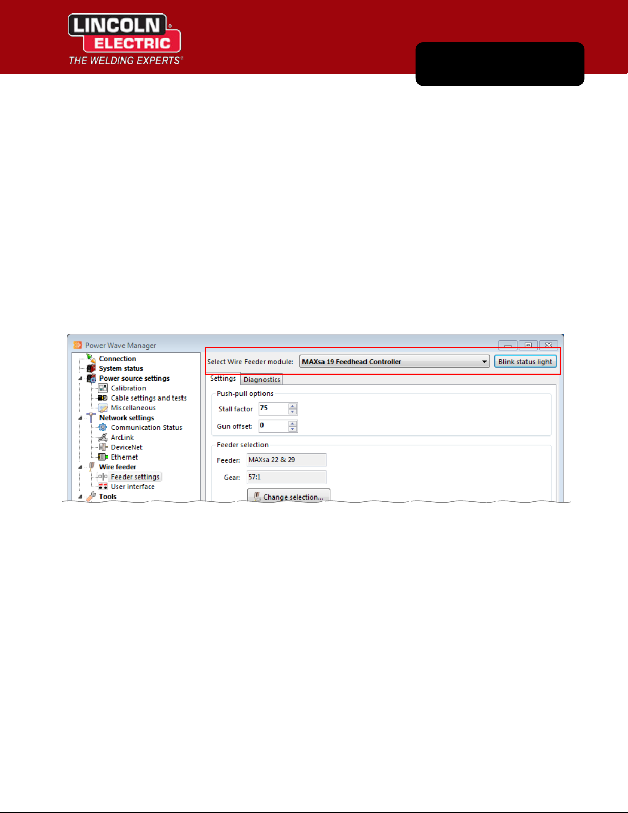
Chapter 8
Wire Feeder
The Wire Feeder section contains settings and diagnostic information for any wire feeders and user
interfaces attached to the Welding Power Source to which you are currently connected with Power Wave®
Manager.
Feeder Settings
In the Feeder Settings section, you can fine tune the behavior of the wire feeders connected to this Welding
Power Source.
Multiple Wire Feeders
If the system to which you have connected (using Power Wave® Manager) contains more than one wire
feeder module, Power Wave® Manager displays the different modules in the Select Wire Feeder module
drop-down. Click the drop-down and select the wire feeder for which you would like to view settings.
Figure 8.1 Multiple Wire Feeder Module Drop-down
If you’re not sure the selection in the drop-down refers to the actual machine you want to review, click the
Blink status light button. This causes the green status light on the wire feeder to start blinking rapidly, and
you can verify you have the correct device selected in Power Wave® Manager.
IM8002 Power Wave® Manager User Manual 8.1
Page 60

Chapter 8. Wire Feeder Feeder Settings
Settings Tab
Under the Settings tab, you can change the stall factor and gun offset for push-pull operation, as well as
change the feed head and gear type. Table 8.1 explains the fields in more detail.
Figure 8.2 Wire Feeder Settings Tab
Table 8.1 Fields on the Settings Tab
Field Description
Stall factor
Gun offset
Feeder and Gear
The Stall factor controls the stall torque of the push motor when using a push-pull
gun. The wire feeder is factory set to not stall unless there is a large resistance to
feeding wire. The stall factor can be reduced to stall more easily and possibly
prevent the feeder wire from bird nesting.
Increasing the stall factor raises the motor torque and decreasing the stall factor
lowers the motor torque. Do not increase the stall factor more than necessary. A
high stall factor may increase the occurrence of bird nesting and a low stall factor
may cause the wire to burn back to the tip.
NOTE | If you are experiencing bird nests, check for other feeding problems
before adjusting the stall factor.
The push-pull Gun offset option adjusts the wire feed speed calibration of the pull
motor. The procedure should only be performed when other possible corrections
do not solve the push-pull feeding problems. Refer to the Operator Manual for your
wire feeder for more information.
If you need to change the feeder or the gear ratio, click the Change selection button
and make your selections from the drop-downs. This process could take some time
and disable certain functions in Power Wave® Manager until the process is
complete.
STOP | Power Wave® Manager resets the Welding Power Source when you click
OK to change feeder or gear ration. Be sure the machine is not welding.
NOTE | The Feeder selection options are only available for feeders that support
custom selections and are not available if the wire feeder requires the use of DIP
switches to make these selections.
8.2 Power Wave® Manager User Manual IM8002
Page 61
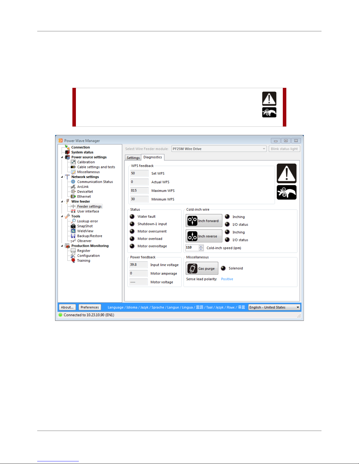
Feeder Settings Chapter 8. Wire Feeder
Diagnostics Tab
You can use the Diagnostics tab to troubleshoot and verify the operational state of your wire feeder. If you
have multiple wire feeders connected to this welding power source, you can select the wire feeder from
the Select Wire Feeder module drop-down at the top of the window (Figure 8.1 on page 8.1).
STOP | Buttons on this tab control the wire feeder
powered by the Welding Power Source. Be sure
to exercise all appropriate safety procedures when
performing actions on this tab.
IM8002 Power Wave® Manager User Manual 8.3
Figure 8.3 Diagnostics Tab
Page 62

Chapter 8. Wire Feeder User Interface
ield displays the lowest limit to the wire feeder’s
Table 8.2 Fields on the Diagnostics Tab
Option Description
WFS feedback The fields in the WFS feedback section displays the wire feed speed
information coming from the wire feeder. This includes:
Set WFS: This is the wire feed speed that was set in the Weld Profile
being used for the weld or that was set manually on the machine by
the Weld Operator.
Actual WFS: This field displays the actual speed at which the feeder
feeds the wire into the weld.
Maximum WFS: This field displays the uppermost limit to the wire
feeder’s speed capability. This is the highest speed at which the wire
feeder can make a successful weld.
Minimum WFS: This f
speed capability. This is the slowest speed at which the wire feeder
can make a successful weld.
Status These indicators display the current status of the wire feeder to which you
are connected.
Cold-inch Wire In the Cold-inch Wire section, you can use the Inch forward and Inch reverse
buttons to feed the wire through the feeder without welding. The Inching
and I/O status indicator lights let you know that the machine is in use and the
input/output communication status.
The Cold-inch speed (ipm) field allows you to set the speed at which the
machine feeds when you click the inching buttons. This defaults from the
current speed on the wire feeder.
Power feedback The fields in the Power feedback section provide you with the power details
for the wire feeder so you can keep your eyes on the power as you diagnose.
Miscellaneous In the Miscellaneous section, the Gas purge or Flux fill button (depending on
your system) allows you to prepare the wire feeder. The Solenoid indicator
lets you know when the feeder is active when using the button. The Sense
lead polarity field displays the polarity for the machine to which you are
connected.
User Interface
If the Welding Power Source to which you have connected has a user interface module attached, the User
interface section of Power Wave® Manager provides you the ability to configure that module, including
integration of specific welding process configurations (i.e., sequences, schedules, procedures, profiles, and
modes).
Multiple User Interfaces
If there are more than one User Interface connected to this Welding Power Source, the User Interface
section provides a drop-down at the top of the window so you can select which User Interface to configure.
8.4 Power Wave® Manager User Manual IM8002
Page 63
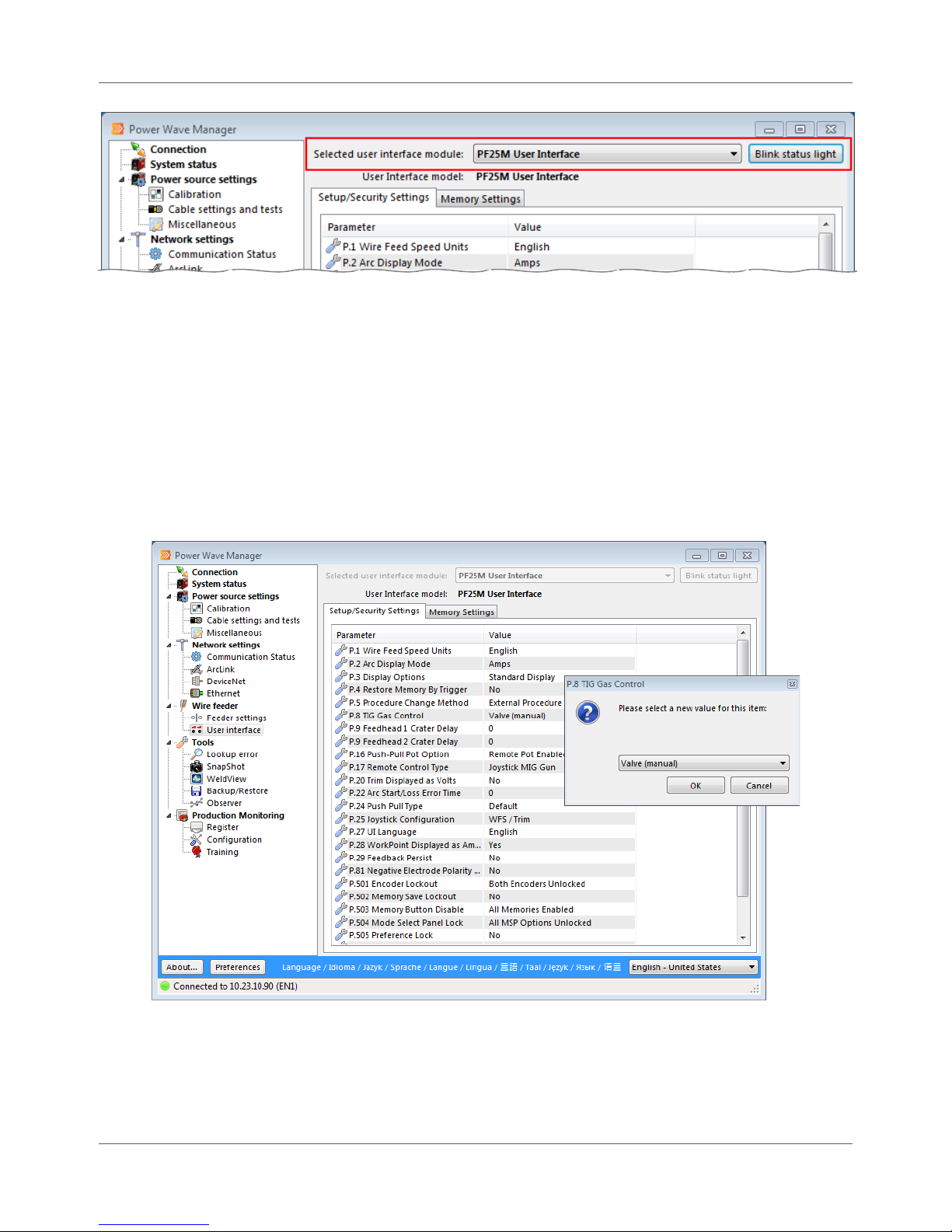
User Interface Chapter 8. Wire Feeder
Figure 8.4 Multiple User Interface Drop-down
If you’re not sure the selection in the drop-down refers to the actual user interface you want to review,
click the Blink status light button. This causes the green status light on the User Interface to start blinking
rapidly, and you can verify you have the correct device selected in Power Wave® Manager.
Setup/Security Settings Tab
The Setup/Security Settings tab allows the user to modify several User Interface parameters and security
settings. The parameters and settings available on this tab vary depending on the User Interface
connected. Please refer to the appropriate Operator Manual for more detailed information on these
parameters.
Figure 8.5 Setup/Security Settings Tab
To change a parameter, double-click the parameter to open the edit window (Figure 8.5). Simply make
your change and click OK.
IM8002 Power Wave® Manager User Manual 8.5
Page 64
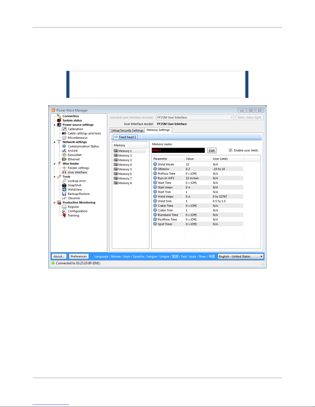
Chapter 8. Wire Feeder User Interface
Memory Settings Tab
The Memory Settings section allows you to configure any of the memory buttons that exist on the User
Interface module(s) attached to your welding system. Memory buttons allow you to preset weld settings
for those welds commonly performed using this power source.
NOTE | If the User Interface is a dual feed head system, click the
appropriate feed head button at the top of the list to access
the memory buttons specific to that feed head.
Memory Buttons
The number of memory slots that appear on the Memory Settings tab depends on the number of
buttons on the physical User Interface. To edit a memory button, simply click the memory button to
select it (e.g., Memory 1 in Figure 8.6). The parameters currently set for that memory button appear
on the right.
Each memory button has text that displays on the Mode Select Panel of the User Interface. To change
this text, click the Edit button next to the Memory name field in Power Wave® Manager. Enter the
new name and click OK.
8.6 Power Wave® Manager User Manual IM8002
Figure 8.6 Memory Settings Tab
Page 65

User Interface Chapter 8. Wire Feeder
Memory Parameters
To edit a parameter, double-click the entry. The parameter’s edit window opens (Figure 8.7). Simply
enter a new value and click OK. The Weld Modes and parameters that are available for the memory
buttons vary depending on the individual User Interface. Please refer to the appropriate Operator
Manual for details on the memory parameters for your User Interface.
Figure 8.7 Editing Memory Parameters
User Limits
If you have a check mark in the Enable User Limits checkbox, the User Interface enables the User limits
fields for certain parameters and enforces the values defined in the those fields (Figure 8.8). With this
checked, if you enter a value that is above the upper limit, Power Wave® Manager automatically
changes that value to match the upper limit when you click OK. The same is true if you enter a value
that is below the lower limit. The system automatically changes that value to match the lower limit.
For example, if the upper User limit is 410 and you enter a value of 654, Power Wave® Manager
automatically changes the value to 410. If the lower User limit is 60 and you enter a value of 50,
Power Wave® Manager automatically changes the value to 60.
If this is not checked, the values in the User limits fields have no effect.
Figure 8.8 Entering a Limit Higher than the User-Specified Limit
The Machine limits displayed represent the absolute limits of this parameter. The User limits, as well
as the entered value, must be within this range. When finished modifying the parameter, click OK to
write the new settings to the machine.
IM8002 Power Wave® Manager User Manual 8.7
Page 66

Chapter 8. Wire Feeder User Interface
THIS PAGE INTENTIONALLY LEFT BLANK.
8.8 Power Wave® Manager User Manual IM8002
Page 67
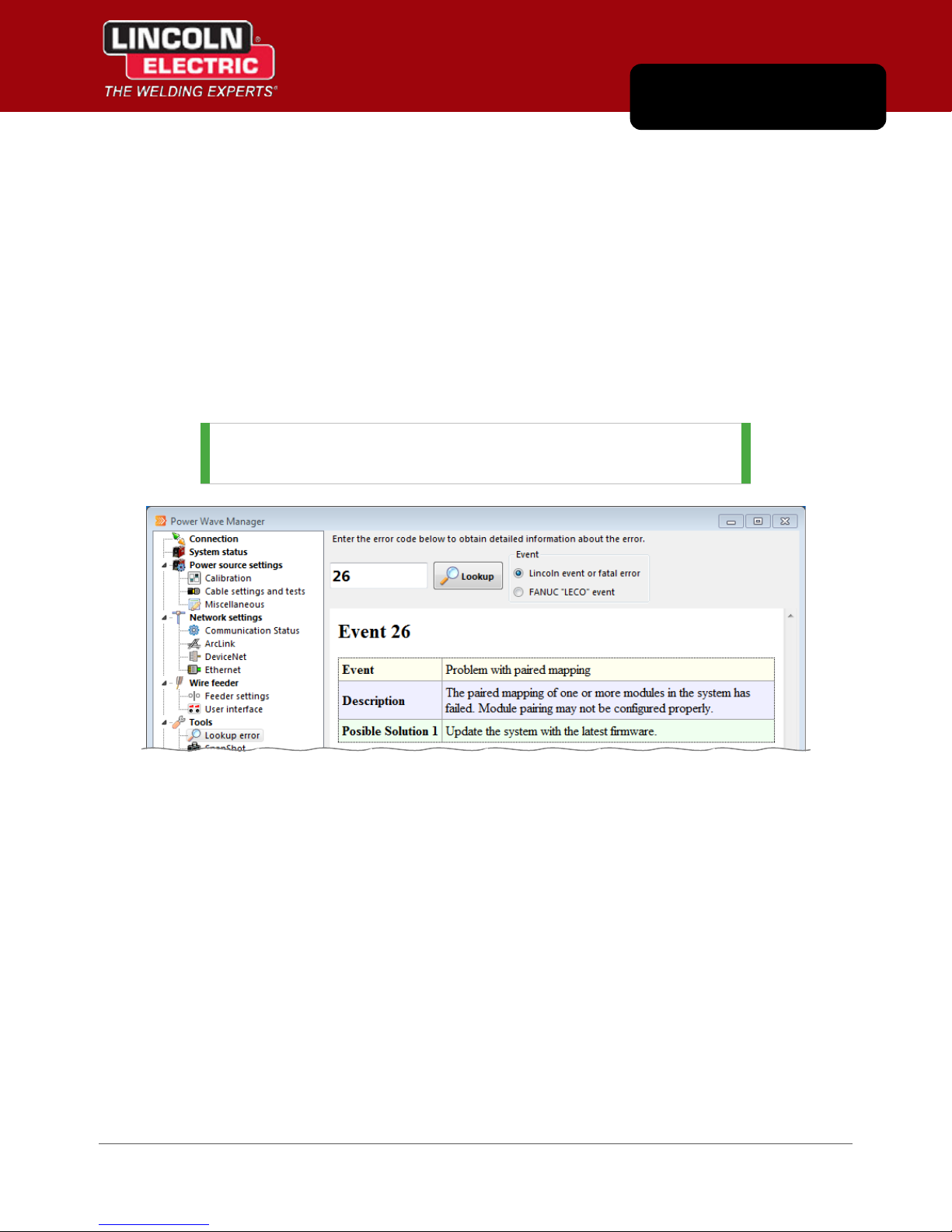
Chapter 9
Tools
The Tools section of Power Wave® Manager provides you with the ability look up an error codes you
receive from a Welding Power Source, create backup and troubleshooting files and view the weld as it is
being made.
Lookup Error
The Lookup error section allows you to obtain information about any error code given by a Welding Power
Source (Figure 9.1). When a Welding Power Source is in a faulted condition, it flashes an error code using
the Status light and blinking in red and green. Please refer to the Operator Manual for the Welding Power
Source for more detailed information on interpreting the error code on the specific power source.
TIP | The Lookup error section is available even if you are not
connected to a Welding Power Source.
Figure 9.1 Lookup Error Tool
To look up a certain error code, choose the type of error from the Event options, type in the error code
number in the text field and click the Lookup button. The system displays a description of the error, as well
as possible solutions or a possible course of action to resolve the error.
IM8002 Power Wave® Manager User Manual 9.1
Page 68

Chapter 9. Tools SnapShot
SnapShot
A SnapShot is a small file that contains very detailed configuration and troubleshooting information
collected from each module in the Welding Power Source, including the User Interface memories. This can
help Lincoln Electric Support to troubleshoot any possible issues that cannot be easily resolved.
When a problem or issue occurs with the Welding Power Source, record a SnapShot of the Welding Power
Source, clear the logs (in the System status section, page 5.1), and attempt to reproduce the issue. If you
can reproduce the issue, record another SnapShot and send both files to Lincoln Electric Support for
analysis.
Figure 9.2 Saving a Troubleshooting File
To save a SnapShot of the Welding Power Source:
Procedure Details
1. Click the SnapShot menu option under the
Tools menu.
2. Click the Save SnapShot button.
3. Leave the default path and click Save.
4. Click OK.
The Save SnapShot dialog opens.
TIP | The default path is the directory set under
the Preferences button (page 4.1).
The system begins generating the file. Depending
on the amount of data, this process could take
several minutes.
Once complete, Power Wave® Manager displays a
confirmation that the file was created successfully.
Once you save the file, you can e-mail it to Lincoln
Electric Support for analysis to the e-mail address
they provide to you.
9.2 Power Wave® Manager User Manual IM8002
Page 69

WeldView Chapter 9. Tools
WeldView
WeldView is a feature of Power Wave® Manager that allows you to capture a high-speed trace of a weld
performed by your Welding Power Source. The trace is a series of data points that the machine stores
while welding. Each record consists of several variables, including amperage and voltage at the time that
the record was written. You can use the weld trace to troubleshoot or fine tune welding performance by
examining the waveform of the weld during starting and ending.
NOTE | Lincoln Electric service personnel may request a weld trace
to aid in resolving welding issues. Click the Save button to
save a trace file that you can send to Lincoln Electric
Support for evaluation.
TIP | If the Acquire new weld trace and Read trace from power
source buttons are disabled, the feature may not be
supported by the connected Welding Power Source.
IM8002 Power Wave® Manager User Manual 9.3
Figure 9.3 WeldView
Page 70

Chapter 9. Tools WeldView
Creating a Weld Trace
The WeldView Wizard allows you to fully configure the trace before starting it, including the trace
frequency, the event that begins the trace (i.e., the trigger event), and if you want to record an extra
channel with the trace.
Figure 9.4 WeldView Wizard
To capture a weld trace:
Procedure Details
1. Select to Tools > WeldView from the
navigation tree.
2. Click the Acquire new weld trace button
on the top toolbar.
3. Choose your trace settings and click Next.
The WeldView Wizard window opens to the trace
settings step (Figure 9.4).
The trigger settings step displays.
9.4 Power Wave® Manager User Manual IM8002
Page 71

WeldView Chapter 9. Tools
Procedure Details
4. If you want the trace to begin only when a
specific event occurs, place a check mark in
the Use trigger checkbox.
5. Select the event from the drop-down.
6. Enter the specific value of the event in
the text field.
7. Click Next.
8. Make the weld with the power source.
9. Once you complete the weld, click the
Next button.
You can skip to step 7 if you do not want to use a
trigger. Make sure there is no check mark in the
Use trigger checkbox.
The Perform weld step displays.
The status light on the Welding Power Source
changes to solid green to indicate the machine is
currently welding.
The power source transfers the data to Power
Wave® Manager and displays it on the Weld data
and Charts tabs.
TIP | To transfer the data from the power
source manually or re-read the last trace made,
simply click the Read trace from power source
button.
Weld Data Tab
On the Weld data tab, Power Wave® Manager displays the data collected from the weld trace in tabular
form. Scroll through the data to review the information (Figure 9.5).
Figure 9.5 WeldView Data in Tabular Form
Charts Tab
The Charts tab (Figure 9.3 on page 9.3) displays a line graph for each aspect of the weld you traced,
including raw voltage, raw current and more. You can scroll through the charts to review the information.
If you want to review the charts in more detail, click the zoom icons. The Zoom in icon ( ) displays the
IM8002 Power Wave® Manager User Manual 9.5
Page 72
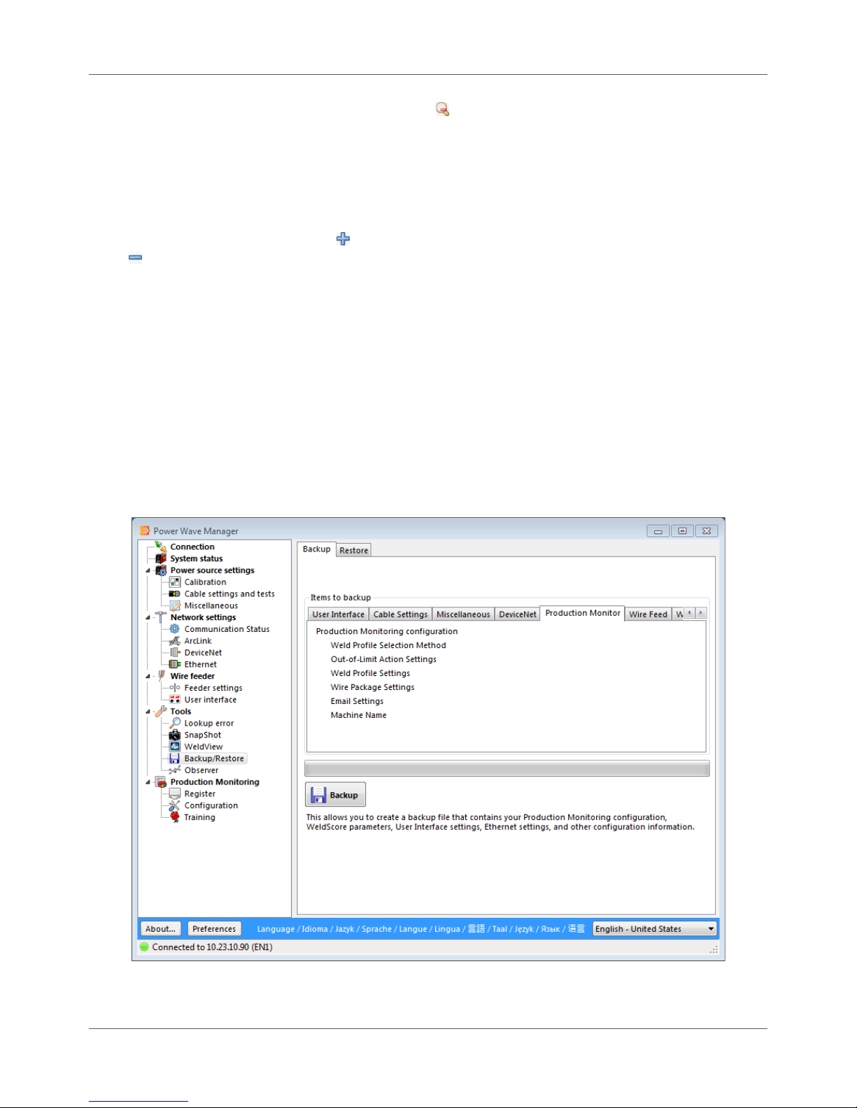
Chapter 9. Tools Backup/Restore
data in smaller segments of time. The Zoom out icon ( ) condenses data and displays the time segments
in larger segments.
For example, if your chart currently displays one second of data segmented every millisecond and you click
the Zoom in icon, the chart begins to expand that one second into parts of a second. When you click the
Zoom out icon, the display condenses again to show you the data segmented every millisecond. (Displays
vary depending on the weld data.)
You can also click the Max Zoom icon ( ) to quickly display the most time segments or click the Min Zoom
icon ( ) to view the fewest time segments.
Backup/Restore
The Backup/Restore section of Power Wave® Manager allows you to save Welding Power Source settings
(e.g., memory configuration, lockout parameters, and network settings) to a backup file. You can use this
file to restore the saved settings at a later time to the same Welding Power Source or to a different power
source (e.g., if you want to configure each power source the same way).
Backing Up a Power Source
The Backup tab (Figure 9.6) provides you with the list of information in various categories that you will save
when you click the Backup button. Click through the sub-tabs to see what the backup file could contain.
The backup file will include the information if that information exists on the Welding Power Source.
9.6 Power Wave® Manager User Manual IM8002
Figure 9.6 Backup Tab
Page 73

Backup/Restore Chapter 9. Tools
To create a backup of the Welding Power Source to which you are currently connected:
Procedure Details
1. Click the Backup/Restore menu item.
2. On the Backup tab, click the Backup button.
3. Click OK.
The program prompts you for a location where
you would like to save the file. The default
location is the path you established under the
Preferences button (page 4.1). The file name
defaults to the serial number of the control board
in the Welding Power Source plus the current date
and time.
The system creates the backup file. The backup
could take a few moments.
Restoring a Backup
You can use a backup file to restore the same power source to a previous state, or you can use a backup file
to quickly configure another power source as you set up your production line. When you use a backup file,
you choose the settings you want to restore, and the process overwrites the existing settings on the
connected power source.
IM8002 Power Wave® Manager User Manual 9.7
Figure 9.7 Restoring to a Backup File
Page 74

Chapter 9. Tools Backup/Restore
To load a settings file and overwrite the existing settings on this Welding Power Source:
Procedure Details
1. Click the Backup/Restore menu item.
2. Click the Restore tab.
3. Click the Browse icon ( ) next to the File to
restore field.
4. Navigate to and select the backup file you
want to load into this power source.
5. Click Open.
6. Click the tab for the category of settings you
want to restore.
7. Place a check mark next to each setting you
want to upload to the connected power
source.
The system displays the categories of settings you can
restore.
The Open file dialog appears.
The file extension for a backup file is WMB (Figure
9.7).
The system loads the file and displays the settings
you can restore.
STOP | Use caution when restoring the TCP/IP
configuration option. Only one machine can have a
specific IP address on the network. Restoring the
same IP address to more than one machine can
cause problems on your network. It is
recommended to restore TCP/IP configuration only
to the machine from which it was originally backed
up.
8. Repeat steps 7 and 6 for each category
containing settings you want to restore.
9. Click the Restore button.
After an IP address is restored, the machine must be
reset in order for the setting to take effect. Be sure
the machine is not welding when you reset.
Power Wave® Manager overwrites the selected
settings on the connected power source with the new
settings.
STOP | Depending on the categories and settings
you choose to restore, the Welding Power Source
may reset and interrupt welding. Be sure the power
source is not currently welding.
9.8 Power Wave® Manager User Manual IM8002
Page 75
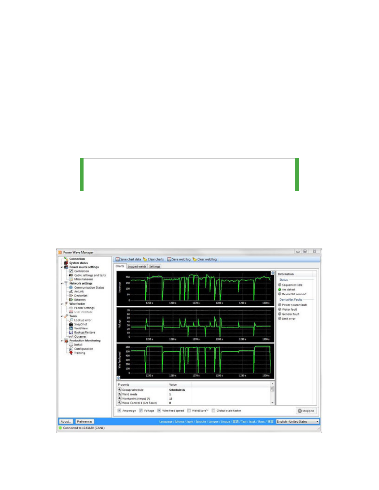
Observer Chapter 9. Tools
Observer
While WeldView gives a detailed view of a portion of a weld with a short duration, the Observer tool graphs
welding feedback at a slower rate over the course of several entire welds. When you begin a weld, Power
Wave® Manager displays a real-time view of the weld. The Observer tool also allows you to change some
basic welding parameters including the Group Schedule, Weld Mode, Workpoint, Trim and other values.
Charts Tab
Power Wave® Manager produces the plots on the Charts tab by periodically reading feedback values from
the Welding Power Source as it welds (Figure 9.8). The data updates whenever the Welding Power Source
output is on. The graphs display Amperage, Voltage, Wire Feed Speed, WeldScore™ (if available), and
Global Scale Factor.
TIP | The checkboxes at the bottom control which graphs you can
see on the Charts tab. Remove the check mark to hide the
graph. Replace the check mark to display it again.
The Information section of the tab displays the status of various system components connected to this
Welding Power Source (if supported). When the indicator is green, this means the status is good. If there is
a fault, the respective gray indicator changes to red.
The Arc detect indicator changes to green when it detects an arc and yellow if the output is on but the
system cannot detect any arc (e.g., when there is not enough voltage to create an arc).
IM8002 Power Wave® Manager User Manual 9.9
Figure 9.8 Observer Tool
Page 76

Chapter 9. Tools Observer
TIP | To save the data in the charts to a tab-delimited text file,
click the Save chart data button on the top toolbar. Click
the Clear charts button to clear the data from the screen
and start fresh.
TIP | Click the plus icon ( ) at each corner of the chart to
collapse the panel next to it (if available).
Logged Welds Tab
The Logged Welds tab displays a list of the welds that were made during the Observer session. The
Observer session begins when you click into the Observer section of Power Wave® Manager. The session
ends when you close Power Wave® Manager or disconnect the power source. Each weld that you create
during this time appears on the Logged welds tab when the Welding Power Source’s output turns off after
you complete the weld.
Figure 9.9 Logged Welds Tab
TIP | To save the log to a tab-delimited text file, click the Save
weld log button on the top toolbar. To clear the log, click
the Clear weld log button.
Table 9.1 Columns on the Logged Welds Tab
Field Description
Date/time This column represents the date and time that the weld began.
Duration (s) This column represents the length of time (in seconds) from the time listed in the
Date/time column to the time the Welding Power Source stopped welding.
Weld mode This column displays the number of the Weld Mode used for this weld.
Workpoint This column displays the value of the workpoint variable for this weld.
WeldScore™ The application displays the WeldScore™ for this weld. A value appears here only if
you used a Weld Profile for this weld and there was a training model created for
that Weld Profile.
9.10 Power Wave® Manager User Manual IM8002
Page 77
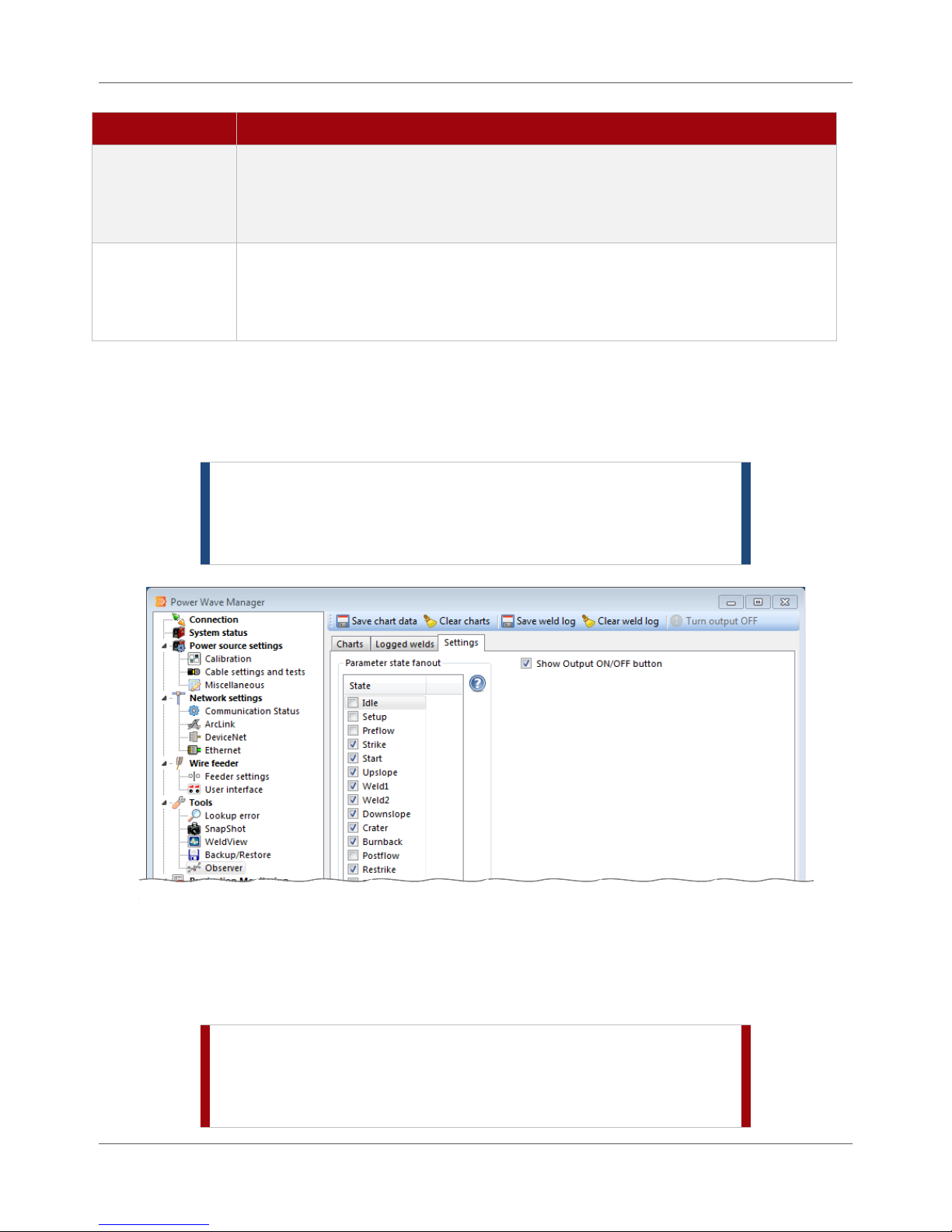
Observer Chapter 9. Tools
Field Description
Average amps Hundreds of times per second, the Welding Power Source takes a measurement of
the arc current being used while the welder is active for this weld. When the weld
is complete, the power source averages those measurements together. The
Average amps column displays that average value for this weld.
Average volts Hundreds of times per second, the Welding Power Source takes a measurement of
the arc voltage being used while the welder is active for this weld. When the weld
is complete, the power source averages those measurements together. The
Average volts column displays that average arc voltage value for this weld.
Settings Tab
The Settings tab allows you to identify which weld sequencer states are modified when you change
a welding setting on the Charts tab (such as Workpoint or Trim). Place a check mark next to the
appropriate states.
NOTE | In order to see a parameter in the charts for the weld, you
must choose the signal before you begin welding. Adding
the signal after completing the weld does not create any
data to display.
If you want to control the machine’s output from within Power Wave® Manager, place a check mark next to
the Show Output ON/OFF button option. This displays a button in the toolbar allowing you to turn the
output of the Welding Power Source on or off. For safety, you must press and hold the Ctrl key on the
keyboard while clicking the button in order for it to turn the power source on or off.
STOP | Use extreme caution when controlling the output from
Power Wave® Manager. The output does not automatically
shut off if you change screens or exit Power Wave®
Manager.
IM8002 Power Wave® Manager User Manual 9.11
Figure 9.10 Settings Tab
Page 78

Chapter 9. Tools Observer
THIS PAGE INTENTIONALLY LEFT BLANK.
9.12 Power Wave® Manager User Manual IM8002
Page 79
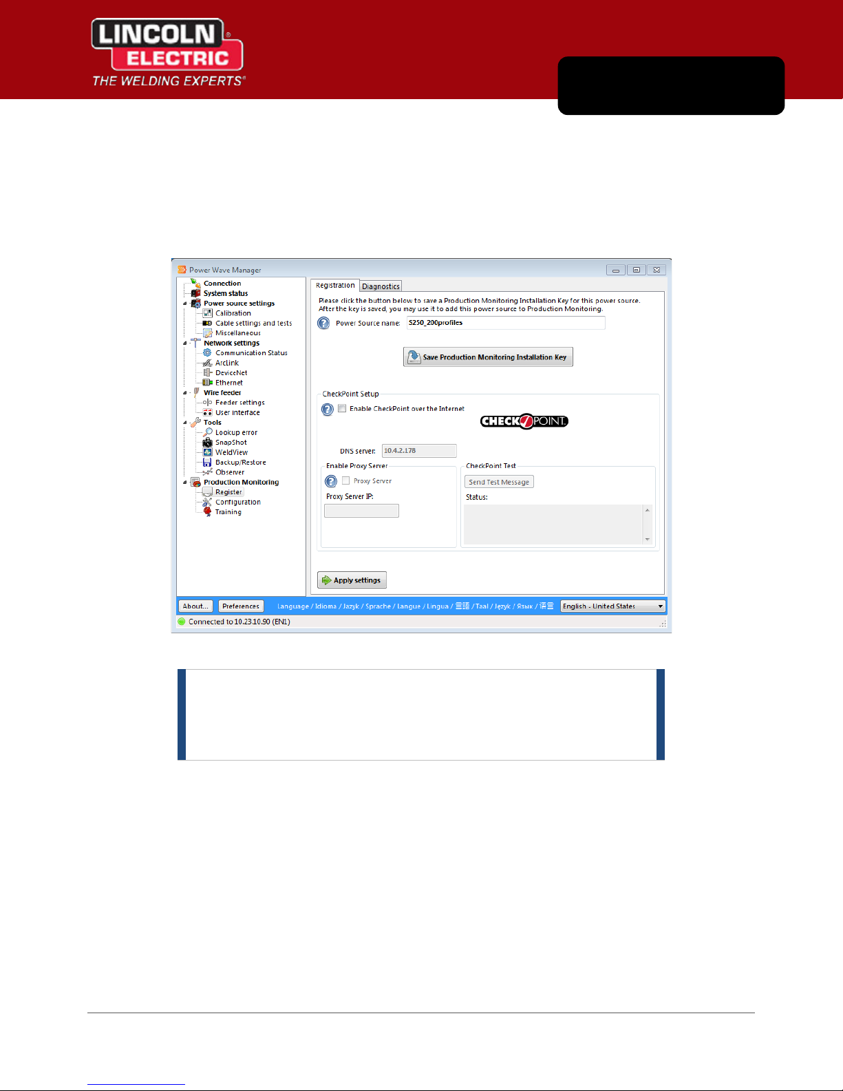
Chapter 10
Production Monitoring
You use the Production Monitoring section of Power Wave® Manager to help you configure the Production
Monitoring™ or CheckPoint™ software on this Welding Power Source (whichever is applicable). You also
use this section to configure Weld Profiles and create training models for the Welding Power Source.
Figure 10.1 Installation Section
NOTE | If you do not see the Production Monitoring section in the
navigation tree, you probably have an older version of
Power Wave® Manager. See page 3.4 for information on
installing the latest version.
IM8002 Power Wave® Manager User Manual 10.1
Page 80

Chapter 10. Production Monitoring Register
Register
The Register section in Power Wave® Manager allows you to perform some of the necessary installation
procedures for the Production Monitoring™ and CheckPoint™ applications, as well as review the current
welds in the memory of the Welding Power Source. For more information on either of these applications,
refer to the Production Monitoring™ User Manual or the CheckPoint™ User Manual, whichever is relevant
for your power source model.
Saving an Installation Key File
Each individual power source has a unique installation key file. The system uses these files to register the
equipment in Production Monitoring™ or CheckPoint™. The steps below walk you through how to save the
installation key file for the Welding Power Source. Each Welding Power Source you add to Production
Monitoring™ or CheckPoint™ needs its own key file.
Figure 10.2 Save an Installation Key File
On the Registration tab of Power Wave® Manager (Figure 10.2), simply click the Save Production
Monitoring Installation Key button and save the file on your computer or network. Close Power Wave®
Manager when finished
STOP | It is recommended that you do not change the text in the
Power Source name field, especially after creating files from
the power source (e.g., training files or backups). Power
Wave® Manager uses the Power Source name to organize
and name weld training, backups, SnapShot files, weld logs,
calibration logs, and more. If you change a name, you will
have to find and load files manually.
CheckPoint™ Setup
The options in the CheckPoint Setup section of this tab allow you to enable CheckPoint™ for the Welding
Power Source to which you are currently connected and to verify that connection. For more in-depth
details on setting up CheckPoint™, please refer to the CheckPoint™ User Manual.
10.2 Power Wave® Manager User Manual IM8002
Page 81
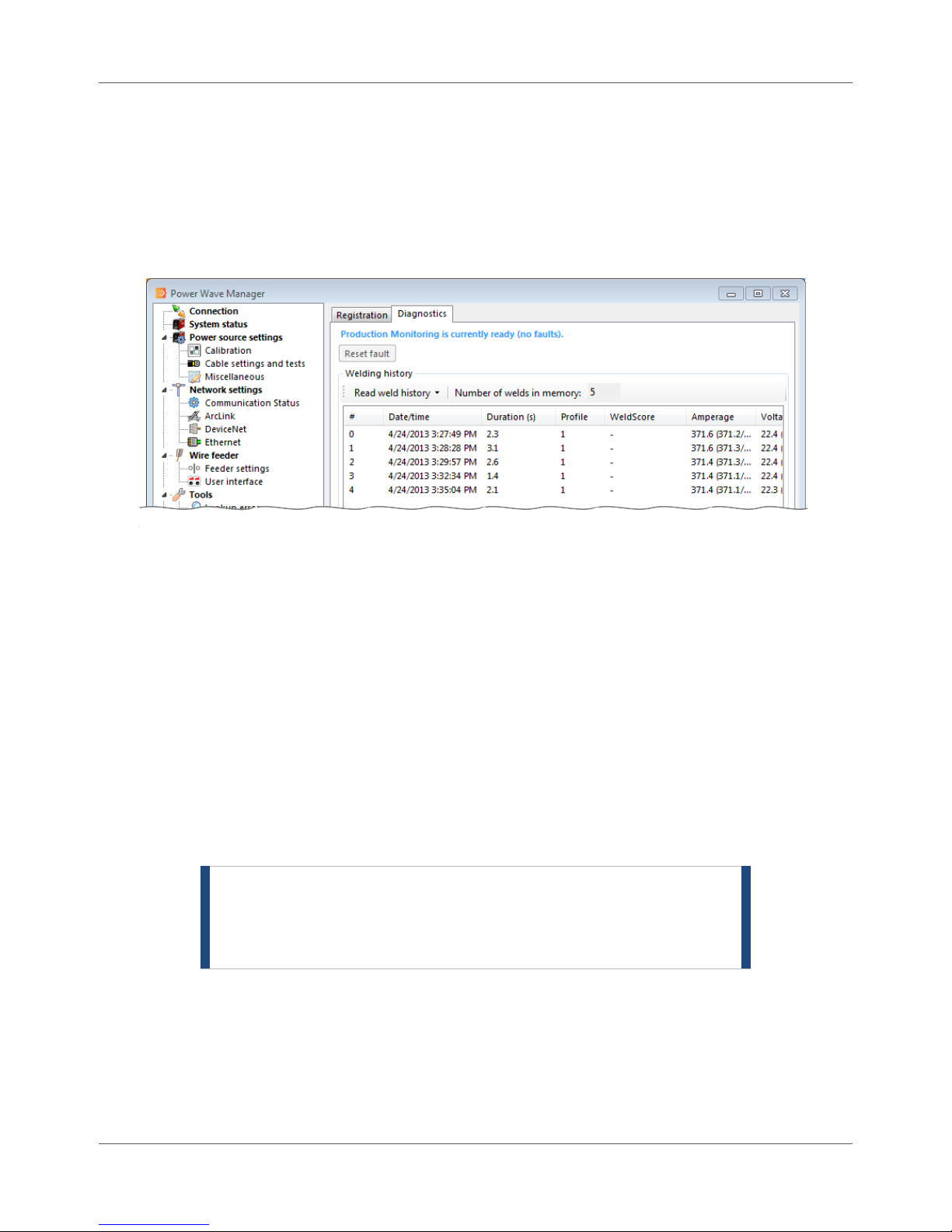
Configuration Chapter 10. Production Monitoring
Diagnostics Tab
The Diagnostics tab provides you with a way to view a list of welds that the power source currently has in
its memory since the last time it powered on (the Number of welds in memory field), as well as a way to
reset the machine if there is an Alarm Latch detected from an out-of-limits condition (click the Reset fault
button). At the top of the tab, Power Wave® Manager displays the current status of the monitoring
software on the power source.
Figure 10.3 Diagnostics Tab
You can view the list of welds in a few different formats, depending on your Welding Power Source. From
the Read weld history drop-down menu, simply select the highest number format that works with your
Welding Power Source:
Format 1 displays basic information about each weld.
Format 2 includes more detailed information about each weld.
Format 3 includes the most information about each weld, including WeldScore™ and part serial
numbers.
Configuration
The Configuration section allows you to set up the Weld Profiles needed on this Welding Power Source,
set up e-mail notifications from the power source, manage the consumables used by the power source
and more.
NOTE | When you finish changing configuration options on one
or more tabs, be sure to click the Apply settings button
to commit your changes. Otherwise, you will lose your
new settings.
Weld Profiles
One of the principal goals of Production Monitoring™ or CheckPoint™ is to report on welds that are outside
of user-defined limits with respect to WeldScore™, current, voltage, wire feed speed and duration. This
goal would be simple to implement if the Welding Power Source were to perform only one type of weld
over and over. However, in practical applications, this is not the case. The assembly of many different
industrial components requires welds of varying type and length.
IM8002 Power Wave® Manager User Manual 10.3
Page 82

Chapter 10. Production Monitoring Configuration
Weld Profiles allows the Welding Power Source to apply different limit settings for each weld that is
performed on a certain part. A Weld Engineer creates a Weld Profile for each weld needed to make a part.
The Weld Profile configures the power source to complete a certain type of weld within certain limits
needed to obtain a specified level of quality. The Weld Profile is selected through a system controller, user
interface or other device prior to initiating each weld, as required by the production sequence.
As an example, consider a part that requires 10 different welds for proper assembly. The Weld Engineer
begins by configuring 10 of the available Weld Profiles, with proper limit settings for each of the different
welds. The Weld Operator can then begin welding the part, selecting the proper Weld Profile for each of
the 10 welds.
There are several ways of selecting the Weld Profile (page 10.4):
Based on welding set point
Through DeviceNet (using a PLC)
Through an ArcLink®-compatible controller
Through memory buttons on the power source’s User Interface
The Welding Power Source can compare the limits stored in a Weld Profile to the real-time data values
collected while performing a weld and take various actions if the weld exceeds these limits (page 10.5).
Power Wave® Manager provides up to 32 Weld Profiles on supported second-generation Welding Power
Sources and up to 200 Weld Profiles on some supported third-generation power sources. In order to make
use of the 200 Weld Profiles on third-generation Welding Power Sources, be sure you have the latest
version of the Welding Power Source firmware (page 3.1) and the latest version of the Power Wave®
Manager software (page 3.4).
Weld Profile Selection Tab
The Weld Profile selection tab allows you to configure how this Welding Power Source chooses the Weld
Profile to use for a weld. Table 10.1 explains each option in more detail. Simply choose the appropriate
option and click the Apply settings button.
Figure 10.4 Example Weld Profile Selection Tab
TIP | If an option does not appear on the Weld Profile selection
tab, the Welding Power Source to which you are connected
does not support that feature.
10.4 Power Wave® Manager User Manual IM8002
Page 83

Configuration Chapter 10. Production Monitoring
Table 10.1 Options on the Weld Profile Selection Tab
Field Description
Select Weld Profile
automatically based on the
last digit of the Workpoint
Allow an external controller to
select the Weld Profile
Select Weld Profile based on
User Interface memory
selection
When you choose this option, the last digit of the welding set point
becomes the Weld Profile number currently in use.
For example, if the welding set point is set to 125, the Power Wave®
will use Weld Profile 5 for the given weld. If the last digit of welding
set point is zero (0), the Power Wave® will use Weld Profile 10.
With this method, the user can access only 10 of the available Weld
Profiles in Power Wave® Manager, constricting procedure
adjustments. Despite these limitations, this method is simple and
effective, and may be the preferred choice for many applications.
When you choose this option for selecting the Weld Profile, you tell
the Welding Power Source to provide an external controller (e.g.,
DeviceNet controller such a PLC or an ArcLink® controller FANUC®
RJ3iB v6.4) with direct access to all Weld Profile numbers on the power
source. The controller must be one that communicates to the power
source over a DeviceNet or ArcLink® network.
When you choose this option, you have configured the Welding Power
Source to use the memory buttons on the connected User Interface to
select the Weld Profile.
This method offers ease of use and straightforwardness in selecting
the Weld Profile, but the number of Weld Profiles that can be selected
are limited by the number of physical buttons on the User Interface.
For example, if there are only six memory buttons on the User
Interface, the Weld Operator can only choose from six Weld Profiles.
With this configuration chosen, if the Weld Operator does not choose
a memory button before performing the weld, the power source uses
the last Weld Profile by default. On second-generation Welding Power
Sources and third-generation power sources that have not upgraded,
this means Profile 32. On third-generation Welding Power Sources
that support this feature, this means Profile 200. See page 10.3 for
more details on Weld Profiles.
Select Weld Profile based on
Analog Interface I/O
When you select this option, the I/O from the analog interface is
configured to choose the Weld Profile.
Out-of-Limit Actions Tab
On the Out-of-limit actions tab, you tell this Welding Power Source what action to take when a weld
exceeds limits established on the Profile limits tab (page 10.7). You can also provide the Welding Power
Source with a short amount of tolerance time before it takes that action. The Out-of-limits tolerance fields
represent the total accumulative amount of time the weld can be outside the limit before the selected
action occurs.
IM8002 Power Wave® Manager User Manual 10.5
Page 84

Chapter 10. Production Monitoring Configuration
When setting the Out-of-limit tolerance for WeldScore™, remember that the sample rate is 0.25 seconds.
You should choose a tolerance value according to the fewest number of samples you want to include. For
example, a value of 0.3 seconds in the Out-of-limit tolerance field only ensures one sample. A value of 0.6
seconds ensures two samples. And so on. We recommend no less than three to five samples, which means
setting your tolerance between 0.8 seconds to 1.3 seconds (or greater as appropriate).
STOP | If you set the Out-of-limit tolerance field for a long time
period, any welds that are shorter than this tolerance will
never trigger the action you select.
For example, John at Advanced Manufacturing set the
tolerance for the Action on voltage limit to 2.0 seconds
(where the normal range might be 0.5 to 1.5 seconds). The
welds made yesterday each took around one second to
complete. There was a problem with the welder, and the
arc voltage ran too low all day. Since the voltage was not
out of limits longer than 2.0 seconds for over the course of
each weld, no one knew until the end of the day and all
parts had to be scrapped and redone.
10.6 Power Wave® Manager User Manual IM8002
Figure 10.5 Out-of-Limits Tab
Page 85

Configuration Chapter 10. Production Monitoring
TIP | If the Action on WeldScore limit value field is grayed out,
either the power source does not support WeldScore™ or
the power source has older firmware that needs to be
updated. See page 3.1 for details on upgrading the power
source’s firmware.
Table 10.2 Available Actions When a Weld is Out of Limits
Field Description
Log Event This option tells the Welding Power Source to create an event log entry to record
that the weld was out of limits. The power source continues welding, even if the
weld does not meet limits set on the Weld Profile.
Fault System If you select this option, the power source will stop the weld currently in progress
when it detects the weld has gone outside the limits set by the Weld Profile. The
Weld Operator can make adjustments and begin welding again.
Alarm Latch When you select this option, a weld that goes outside the limits set by the Weld
Profile causes the power source to enter into a faulted state when the weld ends
(also known as a “latched fault”). In order for the power source to continue
welding, the Weld Operator must clear the fault.
You can reset an Alarm Latch fault on the Diagnostic tab under Production
Monitoring > Register (page 10.3), or by cycling the power to the Welding Power
Source (off then back on).
Profile Limits Tab
The Profile limits tab is where you set limits or adjust trained limits for every Weld Profile available to the
Welding Power Source. Each power source stores all Weld Profiles that are available, but it can only access
the profiles based on the choice you make on the Weld Profile selection tab (page 10.4). You can set the
profile limits manually on the Profile limits tab or you can teach the power source what you consider to be
a weld within limits.
STOP | Be sure you plan your Weld Profiles before you begin. See
page 11.1 for more details.
STOP | For information on training a weld for a Weld Profile, please
refer to Chapter 11.
IM8002 Power Wave® Manager User Manual 10.7
Page 86
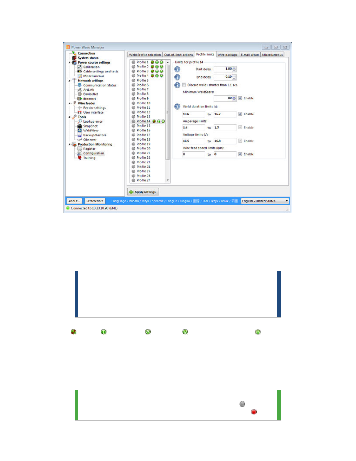
Chapter 10. Production Monitoring Configuration
Figure 10.6 Profile Limits Tab
To change settings in a particular Weld Profile, simply click the Weld Profile to select it and make changes
to the fields on the right. Place a check mark in the Enable checkbox to tell the power source to use that
limit for the profile. (If the values are zero (0) or there is no check mark next to Enable, the system
automatically ignores the limit.) Remember to click the Apply settings button to commit your changes.
Table 10.3 explains each of the limits available.
NOTE | When you enable the Minimum WeldScore option, you can
only set the Weld duration limit and/or the Wire feed speed
limit. Since you must train a weld in order for WeldScore™
to be effective, the trained weld already includes the
amperage and voltage limits.
Next to each Weld Profile in the list are icons that represent each limit available in that Weld Profile:
WeldScore ( ), Time ( ), Amperage ( ), Voltage ( ), and Wire Feed Speed ( ).
If the Weld Profile contains an active limit (i.e., a check mark in the Enabled checkbox) with
values greater than zero (0), the green icon appears next to that Weld Profile number.
If the WeldScore™ limit is not enabled and there is a value entered in the field, the icon appears
but is gray.
If the limit is not enabled or the value for the limit is zero (0), the icon does not appear.
TIP | If you have made changes to a Weld Profile and have not
clicked the Apply settings button, the gray icon ( ) at the
beginning of the Weld Profile changes to a red icon ( ).
10.8 Power Wave® Manager User Manual IM8002
Page 87

Configuration Chapter 10. Production Monitoring
WeldScore™ on machines that support this value (if a training model exists
Table 10.3 Limits Available for Each Weld Profile
Field Description
Start delay This is the amount of delay the power source should use when applying
limits at the beginning of this weld. The Start delay is the amount of time (in
seconds) that the power source should wait, directly after the start of a weld,
before it begins to apply the limits entered for this Weld Profile. This option
is necessary because the start of a weld is often unpredictable and may fall
out of limits easily. (The Start delay must be within the range of 0.1 seconds
to 10.0 seconds.)
NOTE | The combined Start delay and End delay times must be 0.7
seconds or greater if the Production Monitoring firmware on the power
source is at revision 4. If the total is less than 0.7, Power Wave® Manager
automatically adjusts the Start delay value so the total equals 0.7 seconds.
If the Production Monitoring firmware revision is 5 or greater, the
combined Start delay and End delay times must be 0.4 or greater. If the
total is less than 0.4, Power Wave® Manager automatically adjusts the
Start delay value accordingly.
End delay This is the amount of delay the power source should use when applying
limits at the end of this weld. The End delay is the amount of time (in
seconds) directly before the end of a weld that the power source should
stop applying the limits entered for this Weld Profile. This option is
necessary because, at the end of a weld, the set points for the Welding
Power Source are often different than the rest of the weld (e.g., if the power
source is in a burn-back state). The End delay must be within the range of
0.1 seconds to 10.0 seconds.
Discard welds shorter
than “n” seconds
(where “n” is the Start
delay time plus the End
delay time)
Place a check mark next to this option to tell Production Monitoring™ or
CheckPoint™ that it should not record welds where the duration of the weld
is shorter than the combined Start delay and End delay times.
If this option is unchecked, welds that are greater than 0.4 seconds but less
than the Start plus End delay time will be recorded but will be marked as a
Short Weld.
Minimum WeldScore Every quarter of a second, the Welding Power Source compares the
performance of the current weld against the trained weld for the selected
Weld Profile. When the weld is complete, the power source averages those
measurements together for an overall WeldScore™.
The Minimum WeldScore field allows you to enable the action you selected
for WeldScore™ on the Out-of-limit actions tab (page 10.5). If the overall
WeldScore™ for the weld falls below the value you enter here, the system
performs the action you selected in the Action on WeldScore limit drop-down
on the Out-of-limit actions tab.
Even if you do not have the alerts enabled, the power source still calculates
IM8002 Power Wave® Manager User Manual 10.9
Page 88

Chapter 10. Production Monitoring Configuration
for that Weld Profile) and displays the value in the system.
Field Description
NOTE | The default, as well as minimum, value for this setting is 80. If
you need to set a minimum WeldScore™ limit of less than 80 to prevent
your welds from triggering limit alerts, either the training was performed
incorrectly or a variable has changed since the original training was done.
The Weld Profile should be retrained instead of lowering the minimum
WeldScore™ value.
NOTE | If the Minimum WeldScore field is grayed out, either the power
source does not support WeldScore™ or the power source has older
firmware that needs to be updated. See page 3.1 for details on upgrading
the power source’s firmware.
Weld duration limits (s) Enter the minimum and maximum amount of time (in seconds) that you
consider acceptable for a weld made using this Weld Profile. If the overall
duration of the weld falls below the minimum value or above the maximum
value set for the weld, the system considers that “out of limit”. When this
happens, the power source performs the action you selected in the Action on
duration limit drop-down on the Out-of-limit actions tab (page 10.5).
Amperage limits Enter the minimum and maximum amps for the arc current you consider
acceptable for a weld made using this Weld Profile. If the overall amperage
used to make the weld falls below the minimum value or above the
maximum value set for the weld, the system considers that “out of limit”.
When this happens, the power source performs the action you selected in
the Action on amperage limit drop-down on the Out-of-limit actions tab
(page 10.5).
Voltage limits (V) Enter the minimum and maximum volts for the arc voltage you consider
acceptable for a weld made using this Weld Profile. If the overall voltage
used to make the weld falls below the minimum value or above the
maximum value set for the weld, the system considers that “out of limit”.
When this happens, the power source performs the action you selected in
the Action on voltage limit drop-down on the Out-of-limit actions tab (page
10.5).
Wire feed speed limits
(ipm)
Enter the minimum and maximum speed (in inches per minute) for the wire
feeder that you consider acceptable for a weld made using this Weld Profile.
If the overall wire feed speed used to make the weld falls below the
minimum value or above the maximum value set for the weld, the system
considers that “out of limit”. When this happens, the power source
performs the action you selected in the Action on wire feed speed limit drop-
down on the Out-of-limit actions tab (page 10.5).
10.10 Power Wave® Manager User Manual IM8002
Page 89
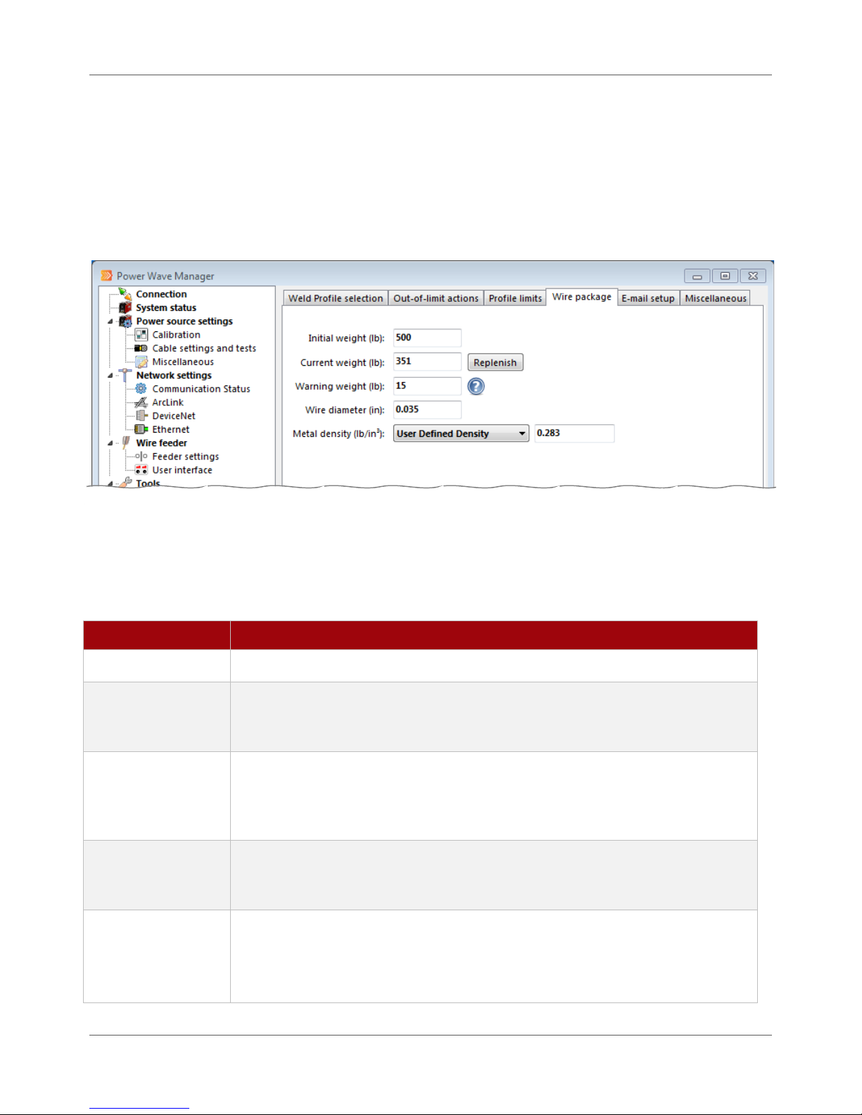
Configuration Chapter 10. Production Monitoring
Wire Package Tab
In order for Power Wave® Manager, Production Monitoring™ or CheckPoint™ to notify you when the
consumable on the Welding Power Source is running low or to allow the monitoring software to calculate a
variety of values, you need to enter the details of the consumable into the power source. You use the Wire
package tab in Power Wave® Manager to do this. Simply enter the details of the consumable and click the
Apply settings button. Table 10.4 explains the fields in more detail.
Figure 10.7 Wire Package Tab
Once you restock the power source after it runs out, click the Replenish button to reset the Current weight
field to the same value as the Initial weight field, provided the new wire is the same. Remember to click
the Apply settings button to commit the change to the power source.
Table 10.4 Fields on the Wire Package Tab
Field Description
Initial Weight Enter the original weight of the wire package, as indicated on the container.
Current weight If the package is partially used, you can enter the current weight of the package
in this field. However, if the package is new, this weight should be the same as
the Initial weight field.
Warning weight The power source can generate notifications to replace the wire package when it
gets low. You can set the alert for Production Monitoring™ on the E-mail setup
tab (page 10.12) and in each user’s account in the main CheckPoint™ application.
Both applications rely on the value entered in the Warning weight field.
Wire diameter Enter the diameter of the wire loaded for the power source. The power source
uses the diameter of the wire when calculating several values that it sends to
Production Monitoring™ or CheckPoint™.
Metal density
From the drop-down, select the density of the metal from which the wire is
composed. If none of the available options apply to the wire loaded into the
power source, select User Defined Density from the drop-down and enter the
density value in the text field that appears.
IM8002 Power Wave® Manager User Manual 10.11
Page 90
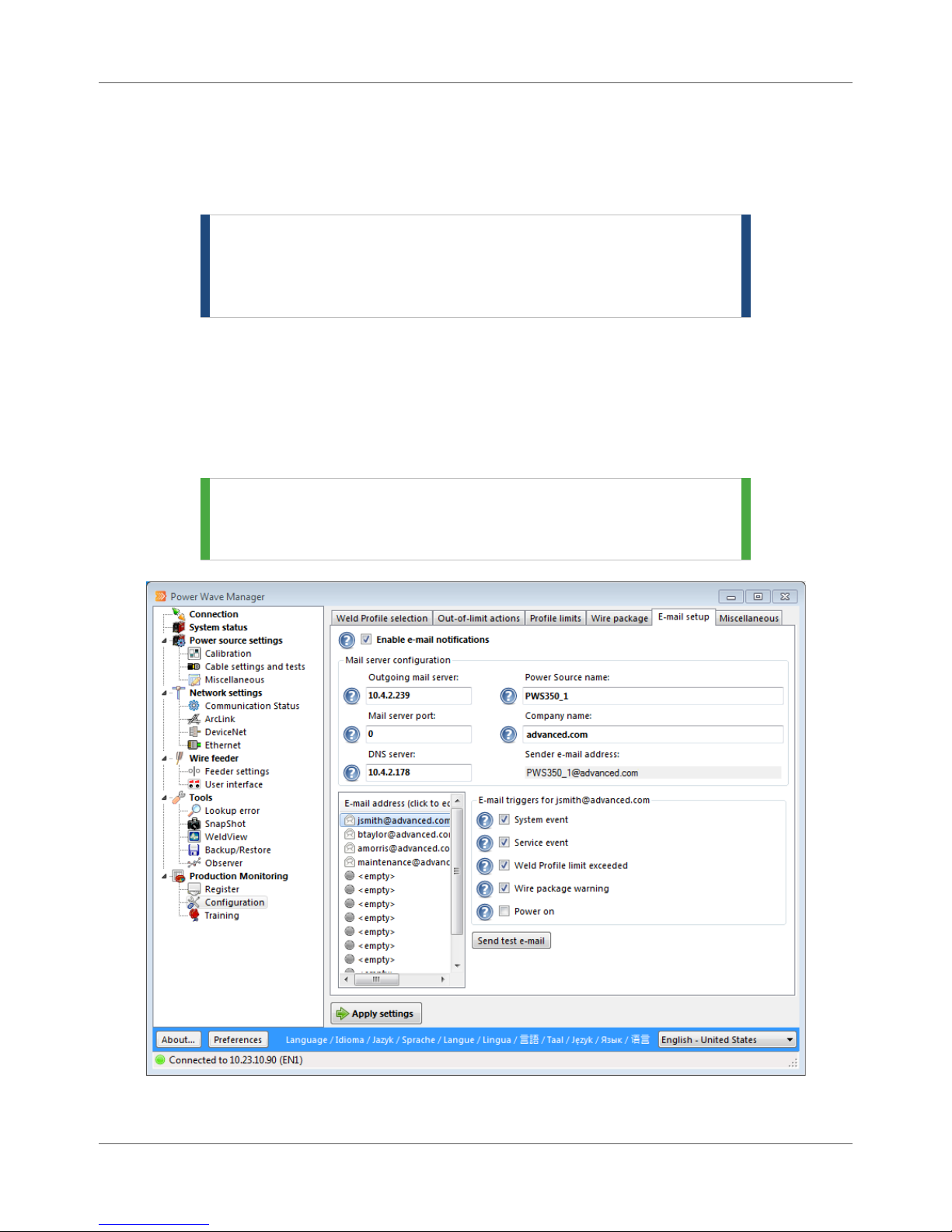
Chapter 10. Production Monitoring Configuration
E-mail Setup Tab
The E-mail setup tab provides you with the ability to configuration e-mail alerts (such as system events and
wire package warnings) for up to 12 e-mail addresses. This requires collecting a bit of information before
you begin.
NOTE | When you enable CheckPoint™, the options on this tab are
disabled. E-mail notifications are processed from the data
center rather than by the power source. Please refer to the
CheckPoint™ User Manual for more information.
Before setting up the Welding Power Source to send e-mails, collect the following information:
List of e-mail addresses that will receive e-mail alerts
IP address (or host name) of the SMTP e-mail server
IP address (or host name) of the DNS server the power source should use for e-mail
Port number on which the e-mail server receives e-mail
TIP | Contact your local IT department for assistance on
obtaining the information about the e-mail server or
the DNS server.
10.12 Power Wave® Manager User Manual IM8002
Figure 10.8 E-mail Setup Tab
Page 91

Configuration Chapter 10. Production Monitoring
Mail Server Configuration
The following options allow you to configure the Welding Power Source to send e-mail notifications to
the addresses in the Address Book (page 10.13). Table 10.5 explains these options in more detail.
Table 10.5 Configuration Options on the E-mail Setup Tab
Field Description
Enable e-mail
notifications
Outgoing mail server Enter the IP address of the e-mail server on your network.
Mail server port Enter the port number that the SMTP service uses to connect to the e-mail
DNS server Enter the IP address of your network’s DNS server. This is only required if
Power Source name
and Company name
Sender E-mail Address Power Wave® Manager combines the Power Source name and Company
Place a check mark in the Enable e-mail notifications checkbox to turn on the
e-mail functions of this power source.
server. The standard port number for SMTP servers is 25. Only change this
number if recommended by your local IT department.
you specified a host name for your mail server, rather than an IP address. If
you are unaware of this information, contact your local IT department.
The power source combines these two fields into an e-mail address for the
power source and uses this address for e-mail alerts it generates. Enter the
company’s domain name in the Company name field. There is generally no
need to change the Power Source name field, as it defaults to the current
power source’s name (from the Registration tab) automatically, helping you
maintain a consistent naming convention and ensuring all files using this
name can be easily found and loaded.
name fields to produce an e-mail address for the power source. When the
Welding Power Source sends an e-mail alert to addresses in the address
book, this e-mail address appears as the sender of the e-mail.
Address Book
The Welding Power Source contains an internal address book, capable of storing up to 12 different email addresses (62 characters in length or less). You can configure each address to receive an e-mail
notification when one or more events occur within the Welding Power Source (E-mail Triggers on page
10.14).
IM8002 Power Wave® Manager User Manual 10.13
Page 92

Chapter 10. Production Monitoring Configuration
Figure 10.9 Address Book
To add a user to the address book, click <empty> slot in the address list to activate a text field. Type
the address and press Enter on the keyboard.
To edit an address, simply click on the address and begin typing. Press Enter on the keyboard to
commit your changes.
To delete an address, click on the address and press the Delete key on your keyboard.
TIP | E-mail addresses can contain uppercase and lower case
letters, the digits 0 through 9, the characters! # $ % * / ? | ^
{ } `~ & ' + - = _
The address can contain the period character “.” provided
that it is not the first or last character in the local part of the
address. It also cannot appear two or more times
consecutively.
E-mail Triggers
In the E-mail triggers section, you can select which event(s) in the Welding Power Source generate an
e-mail notification to the address selected on the left. Each time the event occurs that e-mail address
will receive an e-mail.
For example, if you have a check mark next to the Weld Profile limit exceeded option (Figure 10.10)
and a Weld Operator completes a weld whose WeldScore™ is below the minimum score allowed, the
10.14 Power Wave® Manager User Manual IM8002
Figure 10.10 E-mail Triggers
Page 93

Configuration Chapter 10. Production Monitoring
power source will generate an e-mail. If the Weld Operator completes the next weld and the
WeldScore™ is again below the minimum, the power source generates another e-mail.
To assign an e-mail trigger to an e-mail address, simply make sure you have the e-mail address
selected and place a check mark in the checkbox next to the appropriate options. Table 10.6 explains
each one in a little more detail.
Table 10.6 E-mail Triggers
Field Description
System event When a System Event occurs within the Welding Power Source (e.g., a
thermostat fault), when it is reprogrammed with new software, or when one of
its hardware components is replaced, removed, or added, the power source
sends an e-mail if there is a check mark next to this option.
Service event To trigger an e-mail to this e-mail address when a service event occurs, place a
check mark next to this option. The power source uses these events for
specific troubleshooting and reports them during general operation.
Weld Profile limit
exceeded
Wire package
warning
Power on Choosing this trigger causes the power source to send out an e-mail when the
When a completed weld has exceeded one or more of the limits defined in a
given Weld Profile, the power source sends an e-mail message.
When the consumable package reaches the limit set in the Warning weight
field (page 10.11), the power source sends an e-mail to this address when
there is a check mark next to this option.
power source is turned on or reset.
Sending an E-mail Test
Once you have established your e-mail settings and entered the person’s address into Power Wave®
Manager, you can test the e-mail address to make sure the recipient receives e-mail notifications
properly.
To test the e-mail settings, simply click the address in the E-mail address list and click the Send test e-
mail button. The Welding Power Source attempts to send out an e-mail as soon as you click the test
button, but the amount of time it takes for the recipient to receive the e-mail depends on the e-mail
server in your company. If the recipient hasn’t received the e-mail within about half an hour, verify
the address and try again, or contact your IT administrator for assistance.
Miscellaneous Tab
The Miscellaneous tab displays the part serial number, operator ID and consumable lot number currently
being used by the Welding Power Source for the welds that it makes. These numbers can come
automatically from a robotic system, an external controller, or the mobile app, but you can update the
numbers manually in Power Wave® Manager if necessary.
IM8002 Power Wave® Manager User Manual 10.15
Page 94
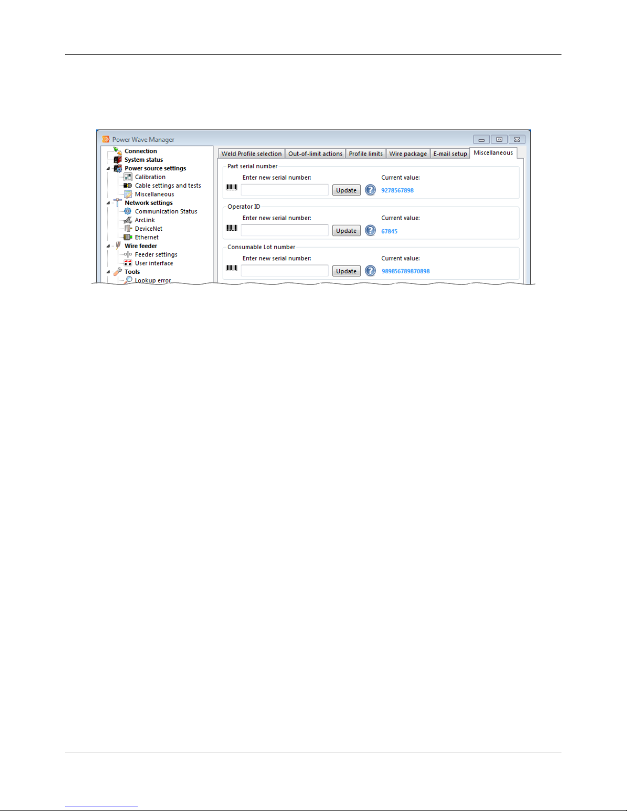
Chapter 10. Production Monitoring Configuration
Click inside the appropriate field and type the serial number. Click the Update button to commit your
changes. Once you update with the new number, Power Wave® Manager displays it in the Current value
field. (You can also click Apply settings to commit changes made to all serial numbers.)
Figure 10.11 Miscellaneous Tab
10.16 Power Wave® Manager User Manual IM8002
Page 95

Chapter 11
Training
For third-generation Welding Power Sources, you need to create training models in order to use
WeldScore™. For second-generation power sources (which do not support WeldScore™), training models
simply help you set limits for current, voltage and wire feed speed. You use both the Profile limits tab
(page 10.7) and the Training section (this chapter) to maintain your Weld Profiles.
Before You Begin Training a Weld
Before you begin setting up your Weld Profiles and creating training models, you need to do some planning.
Planning the Weld Profiles helps make sure that they provide that consistent and repeatable process so
important for an accurate WeldScore™. Be sure you have completed the following before you begin
teaching welds on the Welding Power Source:
Read through this Training chapter in its entirety. Be sure you fully understand the nature of
WeldScore™ and how to create a training model.
Determine how many Weld Profiles you need.
Decide which Weld Profile numbers you want to use on this Welding Power Source.
Decide how many example welds you want to train for each Weld Profile you want to use. If you
train a small number of consistent and repeatable welds, you create a low tolerance for
variability in production. A larger number of training welds allows a bit of flexibility when
making welds in production.
Plan the attributes of each example weld in terms of parameter settings and physical changes.
Remember: You want to create an acceptable average for the training model using these
individual training welds. (Page 11.3 explains the welds to train in more detail.)
WeldScore™
WeldScore™, a new feature available in all third-generation Welding Power Source models (including the
Power Wave® i400, C300, S350, S500 and AC/DC 1000 SD), can be used to support a weld quality control
program. It assigns a score to welds on a 0% to 100% scale that indicates the acceptability of the weld. The
score is based on a comparison to previously trained welding conditions. A weld with a score of 85% to
90% or above can be considered, with a reasonable amount of confidence, to be an acceptable weld.
WeldScore™ can be used independently on the power source or together with Production Monitoring™ or
CheckPoint™.
NOTE | WeldScore™ is not a guarantee of quality and is not
intended to replace a quality control system.
How WeldScore™ Works
Traditional weld-monitoring systems measure current and voltage and must then guess what the Welding
Power Source is trying to do before attempting to determine how well it is actually doing it. WeldScore™ is
built right into the Welding Power Source control system, which gives the control system a significant
advantage by removing the guesswork involved with how the power source should be functioning. In
IM8002 Power Wave® Manager User Manual 11.1
Page 96

Chapter 11. Training WeldScore™
addition to traditional current and voltage measurements, WeldScore™ also looks at 30 to 40 additional
variables that help to make it more reliable and accurate than traditional weld monitoring systems.
Consistency and repeatability are the keys to make your use of WeldScore™ effective. In order to assign a
score, the Welding Power Source must first be taught what is considered to be an acceptable weld. This is
done through the training section of Power Wave® Manager. When a score is assigned to a future weld, it
is done by comparing it to the taught weld. Therefore, it is necessary to teach the Welding Power Source
every weld for which a WeldScore™ is desired. Some examples of when new training is required include
changes in wire feed speed, voltage, joint type or position.
WeldScore™ is able to accommodate both welds with very tight tolerances and welds that have some
acceptable process variation. If the welds taught to the Welding Power Source all have very little variation,
then the only welds that will receive a passing WeldScore™ are ones that meet that very tight tolerance.
Likewise, if there is room for some variation (e.g., small changes in electrical stickout) and the acceptable
variations are used in the training process, then WeldScore™ will assign passing scores to welds that fall
within those variations.
Where to Use WeldScore™
WeldScore™, like any statistical analysis method or technique, requires a controlled process. WeldScore™
works best with a consistent and repeatable process. It will produce the most accurate results with singlepass welds or welds with a small number of passes because, as more passes are used, the process
inherently becomes less repeatable. If there are a large number of variables that are allowed, a significant
amount of variation, the criteria may be too broad for the WeldScore™ to be a meaningful value.
Meaning of the WeldScore™ Value
An instantaneous WeldScore™ value is calculated every 0.25 seconds. The average of these scores over the
entire weld is reported as an overall score displayed on the User Interface, in Production Monitoring™ or in
CheckPoint™.
Keep in mind that this overall WeldScore™ is an average over the entire weld. A weld could still have a high
WeldScore™ even if there is a problem for a short portion of the weld time. For example, if a 50-inch weld
has a score of 95% for 49 inches, but a score of 45% for the last inch, the overall score will be a 94%.
However, that last inch is actually problematic and not acceptable.
The Out-of-Limit features in Power Wave® Manager alert you when the WeldScore™ goes below the
minimum you set for a defined moving window of time. This helps ensure the integrity of the overall
WeldScore™. See pages 10.5 and 10.7 for more details on these features.
11.2 Power Wave® Manager User Manual IM8002
Page 97

Weld Profile Training Chapter 11. Training
Weld Profile Training
You use Weld Profile Training to create training files for the welds you consider acceptable when a Weld
Operator uses that specific Weld Profile. Training helps you generate limits for current, voltage, wire feed
speed and duration for a Weld Profile automatically. Training a weld also generates the necessary data in
order to use WeldScore™. You generally perform three to five training welds in the same manner as they
would be made in normal production. This provides you with a good average on the weld and allows a bit
of flexibility when making welds in production. If you make any welds during training that are outside of
the acceptable limits, you can simply remove those welds from the training.
STOP | You must train a Weld Profile in order for the power source
to provide a WeldScore™.
If your intent is to train a weld to implement WeldScore™ (available on third-generation machines), due to
the volume of data required when training for WeldScore™, the longest weld you can perform for training is
up to 60 seconds (one minute) in duration for a meaningful WeldScore™. Otherwise, the power source
begins to overwrite the old data in the buffer and the WeldScore™ for that Weld Profile will not be
accurate.
On second-generation power sources that do not support WeldScore™, you can still use training models to
help you set limits for current, voltage, wire feed speed and duration. The longest weld you can train is up
to 1260 seconds (21 minutes) before the power source begins to overwrite the data in the buffer. When
you create those training files for each Weld Profile, the power source calculates the limits for you
automatically. You can adjust those calculated limits under Production Monitoring > Configuration >
Profile limits in Power Wave® Manager (page 10.7).
Welds to Train
You should train each Weld Profile that is being used for shorter welds where the welds are consistent and
repeatable. The longer the weld, the less consistent and the less repeatable it becomes. You must train
any Weld Profile you want to use to implement WeldScore™. WeldScore™ works by comparing production
welds to welds that have been trained. In order for an accurate score to be assigned, you should train
between three to five welds at each allowable production extreme for each Weld Profile.
For example, John at Advanced Manufacturing has a weld where the electrical stickout is allowed to vary
from 5/8” to 3/4”. He trained five welds, one at each of these stickouts.
Only train the allowable extremes for the weld. For example, if the stickout can increase to 1” but you
consider this out of limits for an acceptable weld, do not include this in the training. The purpose of
training is to demonstrate to the Welding Power Source the types of welds you consider acceptable.
IM8002 Power Wave® Manager User Manual 11.3
Page 98

Chapter 11. Training Training Profiles
Training Profiles
Be sure you are connected to the Welding Power Source on which you want to train the welds and that all
components are working properly.
STOP | Be sure you have read Before You Begin Training a Weld
on page 11.1 before you continue.
For any Weld Profiles in the list with existing limits, green icons appear that represent each limit recorded
for that profile: WeldScore ( ), Time ( ), Amperage ( ), Voltage ( ), and Wire Feed Speed ( ).
If the Weld Profile contains an active limit (i.e., a check mark in the Enabled checkbox) with
values greater than zero (0), the green icon appears next to that Weld Profile number.
If the WeldScore™ limit is not enabled and there is a value entered in the field, the icon
appears but is gray.
If a limit is not enabled or the value for the limit is zero (0), the icon does not appear.
TIP | Generally when you create a training model for a Weld
Profile, only the WeldScore, Time and Wire Feed Speed
icons appear, and sometimes only the WeldScore icon,
depending on how you have chosen to use the Weld Profile.
11.4 Power Wave® Manager User Manual IM8002
Figure 11.1 Weld Training Window
Page 99

Training Profiles Chapter 11. Training
When a Weld Profile has one or more training files associated with it, the gray icon ( ) next to the Weld
Profile number appears as a star icon ( ). Click the plus icon ( ) to expand the Weld Profile and view
the training files created. The training files use the date and time naming convention and are stored in the
folder selected under the Preferences button (page 4.1). See page 11.7 for details on viewing the limits
calculated for the Weld Profile and for the individual training files.
To train a Weld Profile:
Procedure Details
1. Click Production Monitoring > Training
in the navigation tree of Power Wave®
Manager.
2. Click the Start training button at the top of
the window.
3. Click Yes to send the power source into
Training Mode.
4. Select the Weld Profile you want to train by
using the method chosen for this Welding
Power Source on the Weld Profile selection
tab under Production Monitoring >
Configuration.
5. Physically make all the welds necessary to
set the accepted values for this Weld Profile
(typically between three to five welds).
The Training section opens (Figure 11.1).
The system goes into Training Mode and does not
record new weld history. This helps maintain
production data integrity for the Production
Monitoring™ and CheckPoint™ software
applications.
NOTE | The system clears any unsaved weld
history data from the Production Monitoring™
server computer or the CheckPoint™ data center.
The top of the window now displays the text:
Waiting for next weld to start.
See page 10.4 for details on the Weld Profile
selection tab.
If you have short welds to train, you can train them
in succession with a short pause in between. If,
however, you have long welds to train, train them
one at a time and verify the data has transferred
before beginning the next training weld.
IM8002 Power Wave® Manager User Manual 11.5
NOTE | After you complete a training weld, the
computer must read the data from the Welding
Power Source. If you start a new weld before
Power Wave® Manager reads this data, the new
weld may not be recorded.
In general, it takes about one second to read data
from every 63 seconds of welding. This means a
very long training weld lasting 21 minutes could
take up to 20 seconds to be transfer to the
computer.
Page 100
Chapter 11. Training Training Profiles
Procedure Details
6. Repeat steps 4 and 5 for each Weld Profile
you want to train during this session.
7. Once you have finished training the Weld
Profile(s), click the Stop training button at
the top of the window.
8. Click OK when prompted to take the power
source out of training mode.
9. Verify there is a check mark next to each
Weld Profile you want to save to the
Welding Power Source and click the
Apply settings button.
Enable WeldScore™ Alerts
Power Wave® Manager adds a check mark next to
each profile you have trained during this session and
changes the gray icon ( ) to a star icon ( ). Each
weld training file you add appears with a red icon
( ) to indicate unsaved training data.
The system finishes processing all the data and
displays the information under each Weld Profile
(Figure 11.1 on page 11.4).
This process takes some time and disables certain
functions in Power Wave® Manager until the
process is complete.
NOTE | Power Wave® Manager also resets the
Welding Power Source when you save the Weld
Profiles to the machine.
1. Select Production Monitoring >
Configuration from the navigation tree.
2. Click the Profile limits tab.
3. Select the Weld Profile.
4. Place a check mark in the Enable checkbox
next to the Minimum WeldScore value.
5. Repeat steps 3 and 4 for each Weld Profile
where you want to monitor WeldScore™.
6. Click Apply settings.
The gray WeldScore icon ( ) should change to a
green icon ( ).
Power Wave® Manager saves the changes to the
Welding Power Source.
11.6 Power Wave® Manager User Manual IM8002
 Loading...