

Lincoln Electric POWER WAVE I400 Operator's Manual
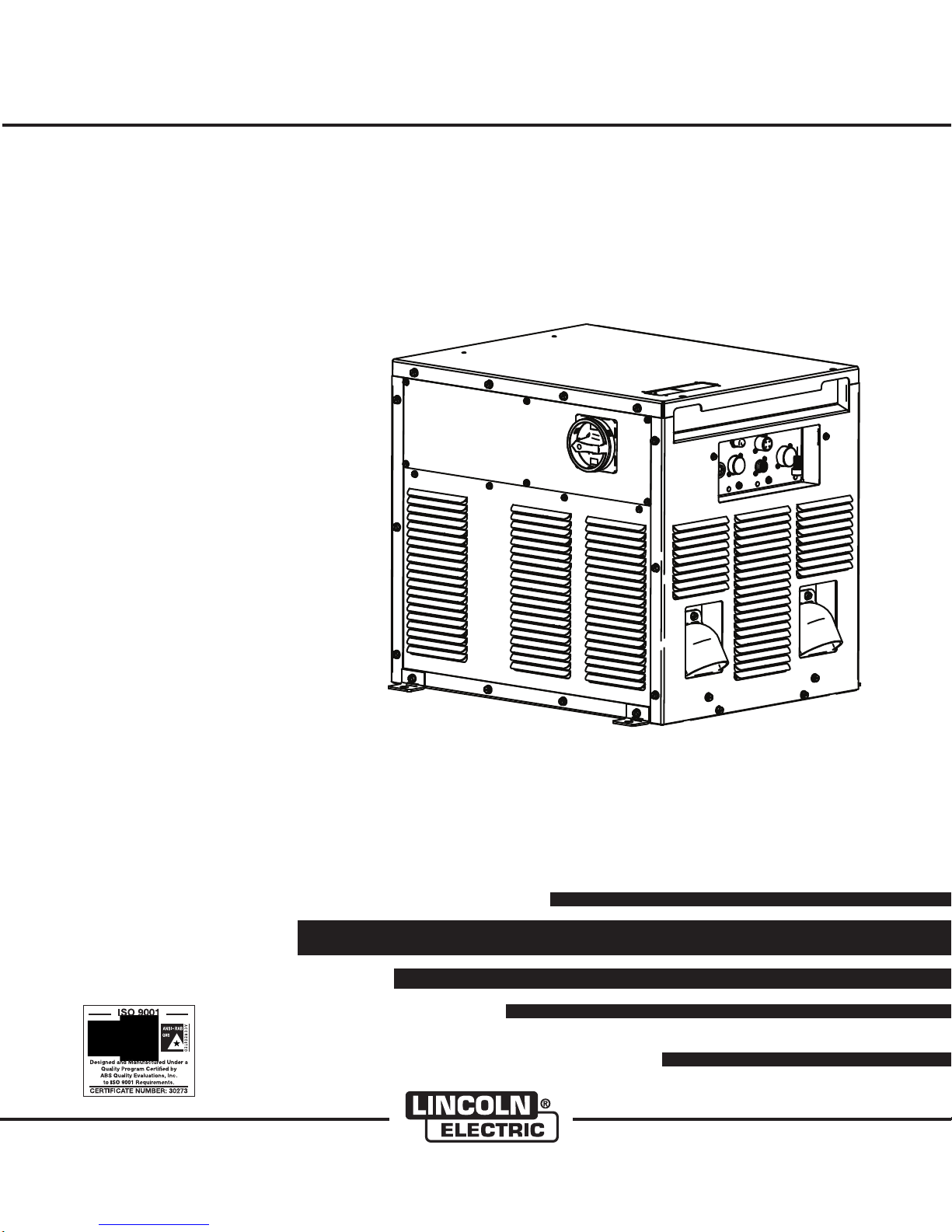
POWER WAVE
®
i400
IM943
October, 2009
For use with machines having Code Numbers:
Safety Depends on You
Lincoln arc welding and cutting
equipment is designed and built
wi th saf ety in mi nd. Ho wev er,
you r over a l l sa f e ty ca n be
increased by proper installation ...
and thoughtful operation on your
part. DO NOT INSTALL, OPER-
ATE OR REPAIR THIS EQUIPMEN T WITHO U T REA D I NG
THIS MANUAL AND THE SAFETY PRECAUTIONS CONTAINED
THR O U GHOUT . And , most
importantly, think before you act
and be careful.
11454, 11454R
OPERATOR’S MANUAL
• World's Leader in Welding and Cutting Products •
• Sales and Service through Subsidiaries and Distributors Worldwide •
Cleveland, Ohio 44117-1199 U.S.A. TEL: 216.481.8100 FAX: 216.486.1751 WEB SITE: www.lincolnelectric.com
Copyright © Lincoln Global Inc.
i
SAFETY
WARNING
CALIFORNIA PROPOSITION 65 WARNINGS
Diesel engine exhaust and some of its constituents
are known to the State of California to cause cancer, birth defects, and other reproductive harm.
The Above For Diesel Engines
ARC WELDING CAN BE HAZARDOUS. PROTECT YOURSELF AND OTHERS FROM POSSIBLE SERIOUS INJURY OR DEATH.
KEEP CHILDREN AWAY. PACEMAKER WEARERS SHOULD CONSULT WITH THEIR DOCTOR BEFORE OPERATING.
Read and understand the following safety highlights. For additional safety information, it is strongly recommended that you
purchase a copy of “Safety in Welding & Cutting - ANSI Standard Z49.1” from the American Welding Society, P.O. Box
351040, Miami, Florida 33135 or CSA Standard W117.2-1974. A Free copy of “Arc Welding Safety” booklet E205 is available
from the Lincoln Electric Company, 22801 St. Clair Avenue, Cleveland, Ohio 44117-1199.
BE SURE THAT ALL INSTALLATION, OPERATION, MAINTENANCE AND REPAIR PROCEDURES ARE
PERFORMED ONLY BY QUALIFIED INDIVIDUALS.
The engine exhaust from this product contains
chemicals known to the State of California to cause
cancer, birth defects, or other reproductive harm.
The Above For Gasoline Engines
i
FOR ENGINE
powered equipment.
1.a. Turn the engine off before troubleshooting and maintenance
work unless the maintenance work requires it to be running.
____________________________________________________
1.b.Operate engines in open,well-ventilated
areas or vent the engine exhaust fumes
outdoors.
____________________________________________________
1.c. Do not add the fuel near an open flame
welding arc or when the engine is running.
Stop the engine and allow it to cool before
refueling to prevent spilled fuel from vaporizing on contact with hot engine parts and
igniting. Do not spill fuel when filling tank. If
fuel is spilled, wipe it up and do not start
engine until fumes have been eliminated.
____________________________________________________
1.d. Keep all equipment safety guards, covers and devices in
position and in good repair.Keep hands, hair, clothing and
tools away from V-belts, gears, fans and all other moving
parts when starting, operating or repairing equipment.
____________________________________________________
1.e. In some cases it may be necessary to remove safety
guards to perform required maintenance. Remove
guards only when necessary and replace them when the
maintenance requiring their removal is complete.
Always use the greatest care when working near moving
parts.
___________________________________________________
1.f. Do not put your hands near the engine fan.
Do not attempt to override the governor or
idler by pushing on the throttle control rods
while the engine is running.
1.h. To avoid scalding, do not remove the
radiator pressure cap when the engine is
hot.
ELECTRIC AND
MAGNETIC FIELDS
may be dangerous
2.a. Electric current flowing through any conductor causes
localized Electric and Magnetic Fields (EMF). Welding
current creates EMF fields around welding cables and
welding machines
2.b. EMF fields may interfere with some pacemakers, and
welders having a pacemaker should consult their physician
before welding.
2.c. Exposure to EMF fields in welding may have other health
effects which are now not known.
2.d. All welders should use the following procedures in order to
minimize exposure to EMF fields from the welding circuit:
2.d.1.
Route the electrode and work cables together - Secure
them with tape when possible.
2.d.2. Never coil the electrode lead around your body.
2.d.3. Do not place your body between the electrode and
work cables. If the electrode cable is on your right
side, the work cable should also be on your right side.
___________________________________________________
1.g. To prevent accidentally starting gasoline engines while
turning the engine or welding generator during maintenance
work, disconnect the spark plug wires, distributor cap or
magneto wire as appropriate.
2.d.4. Connect the work cable to the workpiece as close as
possible to the area being welded.
2.d.5. Do not work next to welding power source.
Mar ‘95
ii
SAFETY
ii
ELE CTR IC SHOCK can
kill.
3.a. The electrode and work (or ground) circuits
are electrically “hot” when the welder is on.
Do not touch these “hot” parts with your bare
skin or wet clothi ng. Wear dry, hole -free
gloves to insulate hands.
3.b. Insulate yourself from work and ground using dry insulation.
Make certain the insulation is large enough to cover your full
area of physical contact with work and ground.
In addition to the normal safety precautions, if welding
mu s t be per form ed und er ele ctri call y haza r dou s
con ditions (in damp locations o r while wearing wet
clothing; on metal structures such as floors, gratings or
scaffolds; when in cramped positions such as sitting,
kneeling or lying, if there is a high risk of unavoidable or
accidental contact with the workpiece or ground) use
the following equipment:
• Semiautomatic DC Constant Voltage (Wire) Welder.
• DC Manual (Stick) Welder.
• AC Welder with Reduced Voltage Control.
3.c. In semiautomatic or automatic wire welding, the electrode,
elect rode reel, we lding head , nozzle or semiautomat ic
welding gun are also electrically “hot”.
3.d. Always be sure the work cable makes a good electrical
connection with the metal being welded. The connection
should be as close as possible to the area being welded.
3.e. Ground the work or metal to be welded to a good electrical
(earth) ground.
3.f.
Maintain the electrode holder, work clamp, welding cable and
welding machine in good, safe operating condition. Replace
damaged insulation.
3.g. Never dip the electrode in water for cooling.
3.h. N ever sim ul taneous ly tou ch elect ri cally “hot” parts of
electrode holders connected to two welders because voltage
between the two can be the total of the open circuit voltage
of both welders.
3.i. When working above floor level, use a safety belt to protect
yourself from a fall should you get a shock.
3.j. Also see Items 6.c. and 8.
ARC RAYS can burn.
4.a. Use a shield with the proper filter and cover
plates to protect your eyes from sparks and
the rays of the arc when welding or observing
open arc welding. Headshield and filter lens
should conform to ANSI Z87. I standards.
4.b. Use suitable clothing made from durable flame-resistant
material to protect your skin and that of your helpers from
the arc rays.
4.c. Protect other nearby personnel with suitable, non-flammable
screening and/or warn them not to watch the arc nor expose
themselves to the arc rays or to hot spatter or metal.
FUMES AND GASES
can be dangerous.
5.a. Weldin g may produce fumes and gases
hazardous to health. Avoid breathing these
fumes and gases. When welding, keep
your head out of the fume. Use enough
ventilation and/or exhaust at the arc to keep
fumes and gases away from the breathing zo ne. When
we l ding w i th el e ctr o des wh i ch req u ire s p eci a l
ve n til atio n suc h as st a inl ess or hard faci n g (s e e
in str uct ion s on cont ain er o r MS DS) or on lead or
cadmi um plated steel and o ther metal s or coatings
which produce highly toxic fumes, keep exposure as
low as possible and within applicable OSHA PEL and
ACGIH TLV limits using local exhaust or mechanical
ventilation. In confined spaces or in s om e c ir cu mst a nce s, ou t doo r s, a resp i rat o r ma y be req uir e d.
Additional precautions are also required when welding
on galvanized steel.
5. b. The operation of welding fume control equipment is affected
by various factors including proper use and positioning of
the equipment, maintenance of the equipment and the specific welding procedure and application involved. Worker
exposure level should be checked upon installation and
periodically thereafter to be certain it is within applicable
OSHA PEL and ACGIH TLV limits.
5.c.
Do not weld in locations near chlorinated hydrocarbon
coming from degreasing, cleaning or spraying operations.
The heat and rays of the arc can react with solvent vapors
form phosgene, a highly toxic gas, and other irritating products.
5.d. Shielding gases used for arc welding can displace air and
cause injury o r d ea th . A lw ay s u se enough ventilation,
especially in confined areas, to insure breathing air is safe.
vapors
to
5.e. Read and understand the manufacturer’s instructions for this
equipment and the consumables to be used, including the
ma t eria l s afet y d ata sh e et (MS D S) and fo l low yo ur
employer’s safety practices. MSDS forms are available from
yo u r wel d ing d ist r ibu t or or f rom t he ma nuf a ctur er.
5.f. Also see item 1.b.
Jan ‘09
iii
SAFETY
iii
WELDING and CUTTING
SPARKS can
cause fire or explosion.
6.a.
Remove fire hazards from the welding area.
If this is not possible, cover them to prevent
Re m embe r th a t we l din g spa r ks an d ho t
materials from welding can easily go through small cracks
an d op eni ngs to a djace nt a reas. A vo id w eld ing nea r
hydraulic lines. Have a fire extinguisher readily available.
6.b. Where compressed gases are to be used at the job site,
special precautions should be used to prevent hazardous
situations. Refer to “Safety in Welding and Cutting” (ANSI
Standar d Z49.1) and t he op erating info rmation fo r t he
equipment being used.
6.c. When not welding, make certain no part of the electrode
circuit is touching the work or ground. Accidental contact
can cause overheating and create a fire hazard.
6.d. Do not heat, cut or weld tanks, drums or containers until the
proper steps have been taken to insure that such procedures
will not cause flammable or toxic vapors from substances
inside. They can cause an explosion even
been “cleaned”. For information, purchase “Recommended
Safe Practices for the
Co n tain ers a n d Pi ping That Have Held Haz a rdo u s
Substances”, AWS F4.1 from the American Welding Society
(see address above).
6.e. Vent hollow castings or containers before heating, cutting or
welding. They may explode.
Sparks and spatter are thrown from the welding arc. Wear oil
6.f.
free protective garments such as leather gloves, heavy shirt,
cuffless trousers, high shoes and a cap over your hair. Wear
ear plugs when welding out of position or in confined places.
Always wear safety glasses with side shields when in a
welding area.
6.g. Connect the work cable to the work as close to the welding
area as practical. Work cables connected to the building
framework or other locations away from the welding area
incre ase the possi bility o f the welding cu rrent pa ssing
through lifting chains, crane cables or other alternate circuits. This can create fire hazards or overheat lifting chains
or cables until they fail.
6.h. Also see item 1.c.
the welding sp ar ks from starting a fire.
though
they have
Preparation
for Welding and Cutting of
CYLINDER may explode
if damaged.
7.a. U se on l y co m pres sed ga s cy l ind e rs
containing the correct shielding gas for the
pr o cess u s ed and pr ope r ly ope r ati n g
re g ulat ors d esig ned f o r th e ga s an d
pressure used. All hoses, fittings, etc. should be suitable for
the application and maintained in good condition.
7.b. A lw ays keep cylinders in an upright po sition securely
chained to an undercarriage or fixed support.
7.c. Cylinders should be located:
• Away from areas where they may be struck or subjected to
physical damage.
• A safe distance from arc welding or cutting operations and
any other source of heat, sparks, or flame.
7.d. Never allow the electrode, electrode holder or any other
electrically “hot” parts to touch a cylinder.
7.e. Keep your head and face away from the cylinder valve outlet
when opening the cylinder valve.
7.f. Valve protection caps should always be in place and hand
tight except when the cylinder is in use or connected for
use.
7.g. R ead and follo w th e i nst ru ction s on com pr ess ed gas
cylinders, associated equipment, and CGA publication P-l,
“Precautions for Safe Handling of Compressed Gases in
Cylinders,” available from the Compressed Gas Association
1235 Jefferson Davis Highway, Arlington, VA 22202.
FOR ELECTRICALLY
powered equipment.
8.a. Turn off input power using the disconnect
switch at the fuse box before working on
the equipment.
8.b. Install equipme nt in accordan ce with the U.S. Nati onal
Electrical Code, all local codes and the manufacturer’s
recommendations.
8.c. Ground the equipment in accordance with the U.S. National
Electrical Code and the manufacturer’s recommendations.
6.I. Read and follow NFPA 51B “ Standard for Fire Prevention
During Welding, Cutting and Other Hot Work”, available
from NFPA, 1 Batterymarch Park, PO box 9101, Quincy, Ma
022690-9101.
6.j. Do not use a welding power source for pipe thawing.
Refer to http://www.lincolnelectric.com/safety for additional safety information.
Jan ‘09

iv
SAFETY
iv
PRÉCAUTIONS DE SÛRETÉ
Pour votre propre protection lire et observer toutes les instructions
et les précautions de sûreté specifiques qui parraissent dans ce
manuel aussi bien que les précautions de sûreté générales suivantes:
Sûreté Pour Soudage A L’Arc
1. Protegez-vous contre la secousse électrique:
a. Les circuits à l’électrode et à la piéce sont sous tension
quand la machine à souder est en marche. Eviter toujours
tout contact entre les parties sous tension et la peau nue
ou les vétements mouillés. Porter des gants secs et sans
trous pour isoler les mains.
b. Faire trés attention de bien s’isoler de la masse quand on
soude dans des endroits humides, ou sur un plancher
metallique ou des grilles metalliques, principalement dans
les positions assis ou couché pour lesquelles une grande
partie du corps peut être en contact avec la masse.
c. Maintenir le porte-électrode, la pince de masse, le câble
de soudage et la machine à souder en bon et sûr état
defonctionnement.
d.Ne jamais plonger le porte-électrode dans l’eau pour le
refroidir.
e. Ne jamais toucher simultanément les parties sous tension
des porte-électrodes connectés à deux machines à souder
parce que la tension entre les deux pinces peut être le
total de la tension à vide des deux machines.
f. Si on utilise la machine à souder comme une source de
courant pour soudage semi-automatique, ces precautions
pour le porte-électrode s’applicuent aussi au pistolet de
soudage.
2. Dans le cas de travail au dessus du niveau du sol, se protéger
contre les chutes dans le cas ou on recoit un choc. Ne jamais
enrouler le câble-électrode autour de n’importe quelle partie
du corps.
5. Toujours porter des lunettes de sécurité dans la zone de
soudage. Utiliser des lunettes avec écrans lateraux dans les
zones où l’on pique le laitier.
6. Eloigner les matériaux inflammables ou les recouvrir afin de
prévenir tout risque d’incendie dû aux étincelles.
7. Quand on ne soude pas, poser la pince à une endroit isolé de
la masse. Un court-circuit accidental peut provoquer un
échauffement et un risque d’incendie.
8. S’assurer que la masse est connectée le plus prés possible
de la zone de travail qu’il est pratique de le faire. Si on place
la masse sur la charpente de la construction ou d’autres
endroits éloignés de la zone de travail, on augmente le risque
de voir passer le courant de soudage par les chaines de levage, câbles de grue, ou autres circuits. Cela peut provoquer
des risques d’incendie ou d’echauffement des chaines et des
câbles jusqu’à ce qu’ils se rompent.
9. Assurer une ventilation suffisante dans la zone de soudage.
Ceci est particuliérement important pour le soudage de tôles
galvanisées plombées, ou cadmiées ou tout autre métal qui
produit des fumeés toxiques.
10. Ne pas souder en présence de vapeurs de chlore provenant
d’opérations de dégraissage, nettoyage ou pistolage. La
chaleur ou les rayons de l’arc peuvent réagir avec les vapeurs
du solvant pour produire du phosgéne (gas fortement toxique)
ou autres produits irritants.
11. Pour obtenir de plus amples renseignements sur la sûreté,
voir le code “Code for safety in welding and cutting” CSA
Standard W 117.2-1974.
PRÉCAUTIONS DE SÛRETÉ POUR
3. Un coup d’arc peut être plus sévère qu’un coup de soliel,
donc:
a. Utiliser un bon masque avec un verre filtrant approprié
ainsi qu’un verre blanc afin de se protéger les yeux du rayonnement de l’arc et des projections quand on soude ou
quand on regarde l’arc.
b. Porter des vêtements convenables afin de protéger la
peau de soudeur et des aides contre le rayonnement de
l‘arc.
c. Protéger l’autre personnel travaillant à proximité au
soudage à l’aide d’écrans appropriés et non-inflammables.
4. Des gouttes de laitier en fusion sont émises de l’arc de
soudage. Se protéger avec des vêtements de protection libres
de l’huile, tels que les gants en cuir, chemise épaisse, pantalons sans revers, et chaussures montantes.
LES MACHINES À SOUDER À
TRANSFORMATEUR ET À
REDRESSEUR
1. Relier à la terre le chassis du poste conformement au code de
l’électricité et aux recommendations du fabricant. Le dispositif
de montage ou la piece à souder doit être branché à une
bonne mise à la terre.
2. Autant que possible, I’installation et l’entretien du poste seront
effectués par un électricien qualifié.
3. Avant de faires des travaux à l’interieur de poste, la debrancher à l’interrupteur à la boite de fusibles.
4. Garder tous les couvercles et dispositifs de sûreté à leur
place.
Mar. ‘93

v
SAFETY
Electromagnetic Compatibility (EMC)
Conformance
Products displaying the CE mark are in conformity with European Community Council Directive of 3 May
1989 on the approximation of the laws of the Member States relating to electromagnetic compatibility
(89/336/EEC). It was manufactured in conformity with a national standard that implements a harmonized
standard: EN 60974-10 Electromagnetic Compatibility (EMC) Product Standard for Arc Welding Equipment.
It is for use with other Lincoln Electric equipment. It is designed for industrial and professional use.
Introduction
All electrical equipment generates small amounts of electromagnetic emission. Electrical emission may be
transmitted through power lines or radiated through space, similar to a radio transmitter. When emissions
are received by other equipment, electrical interference may result. Electrical emissions may affect many
kinds of electrical equipment; other nearby welding equipment, radio and TV reception, numerical controlled
machines, telephone systems, computers, etc. Be aware that interference may result and extra precautions
may be required when a welding power source is used in a domestic establishment.
Installation and Use
The user is responsible for installing and using the welding equipment according to the manufacturer’s
instructions. If electromagnetic disturbances are detected then it shall be the responsibility of the user of the
welding equipment to resolve the situation with the technical assistance of the manufacturer. In some cases
this remedial action may be as simple as earthing (grounding) the welding circuit, see Note. In other cases it
could involve construction an electromagnetic screen enclosing the power source and the work complete
with associated input filters. In all cases electromagnetic disturbances must be reduced to the point where
they are no longer troublesome.
v
Note: The welding circuit may or may not be earthed for safety reasons according to national codes.
Changing the earthing arrangements should only be authorized by a person who is competent to access whether the changes will increase the risk of injury, e.g., by allowing parallel
welding current return paths which may damage the earth circuits of other equipment.
Assessment of Area
Before installing welding equipment the user shall make an assessment of potential electromagnetic problems in the surrounding area. The following shall be taken into account:
a) other supply cables, control cables, signaling and telephone cables; above, below and adjacent to the
welding equipment;
b) radio and television transmitters and receivers;
c) computer and other control equipment;
d) safety critical equipment, e.g., guarding of industrial equipment;
e) the health of the people around, e.g., the use of pacemakers and hearing aids;
f) equipment used for calibration or measurement
g) the immunity of other equipment in the environment. The user shall ensure that other equipment being
used in the environment is compatible. This may require additional protection measures;
h) the time of day that welding or other activities are to be carried out.
L10093 3-1-96H

vi
SAFETY
Electromagnetic Compatibility (EMC)
The size of the surrounding area to be considered will depend on the structure of the building and other
activities that are taking place. The surrounding area may extend beyond the boundaries of the premises.
Methods of Reducing Emissions
Mains Supply
Welding equipment should be connected to the mains supply according to the manufacturer’s recommendations. If interference occurs, it may be necessary to take additional precautions such as filtering of the mains
supply. Consideration should be given to shielding the supply cable of permanently installed welding equipment, in metallic conduit or equivalent. Shielding should be electrically continuous throughout its length. The
shielding should be connected to the welding power source so that good electrical contact is maintained
between the conduit and the welding power source enclosure.
Maintenance of the Welding Equipment
The welding equipment should be routinely maintained according to the manufacturer’s recommendations.
All access and service doors and covers should be closed and properly fastened when the welding equipment is in operation. The welding equipment should not be modified in any way except for those changes
and adjustments covered in the manufacturers instructions. In particular, the spark gaps of arc striking and
stabilizing devices should be adjusted and maintained according to the manufacturer’s recommendations.
vi
Welding Cables
The welding cables should be kept as short as possible and should be positioned close together, running at
or close to floor level.
Equipotential Bonding
Bonding of all metallic components in the welding installation and adjacent to it should be considered.
However, metallic components bonded to the work piece will increase the risk that the operator could
receive a shock by touching these metallic components and the electrode at the same time. The operator
should be insulated from all such bonded metallic components.
Earthing of the Workpiece
Where the workpiece is not bonded to earth for electrical safety, not connected to earth because of its size
and position, e.g., ships hull or building steelwork, a connection bonding the workpiece to earth may reduce
emissions in some, but not all instances. Care should be taken to prevent the earthing of the workpiece
increasing the risk of injury to users, or damage to other electrical equipment. Where necessary, the connection of the workpiece to earth should be made by a direct connection to the workpiece, but in some countries
where direct connection is not permitted, the bonding should be achieved by suitable capacitance, selected
according to national regulations.
Screening and Shielding
Selective screening and shielding of other cables and equipment in the surrounding area may alleviate problems of interference. Screening of the entire welding installation may be considered for special applications.
1
_________________________
1
Portions of the preceding text are contained in EN 60974-10: “Electromagnetic Compatibility (EMC) product standard for arc welding equipment.”
L10093 3-1-96H
TThhaannkk YYoouu
viivii
for selecting a QUALITY product by Lincoln Electric. We want you
to take pride in operating this Lincoln Electric Company product
••• as much pride as we have in bringing this product to you!
The business of The Lincoln Electric Company is manufacturing and selling high quality welding equipment, consumables, and cutting equipment. Our challenge is to meet the needs of our customers and to exceed their expectations. On occasion, purchasers may ask Lincoln
Electric for advice or information about their use of our products. We respond to our customers based on the best information in our possession at that time. Lincoln Electric is not in a position to warrant or guarantee such advice, and assumes no liability, with respect to such information or advice. We expressly disclaim any warranty of any kind, including any warranty of fitness for any customer’s particular purpose,
with respect to such information or advice. As a matter of practical consideration, we also cannot assume any responsibility for updating or
correcting any such information or advice once it has been given, nor does the provision of information or advice create, expand or alter any
warranty with respect to the sale of our products.
Lincoln Electric is a responsive manufacturer, but the selection and use of specific products sold by Lincoln Electric is solely within the control
of, and remains the sole responsibility of the customer. Many variables beyond the control of Lincoln Electric affect the results obtained in
applying these types of fabrication methods and service requirements.
Subject to Change – This information is accurate to the best of our knowledge at the time of printing. Please refer to www.lincolnelectric.com
for any updated information.
CUSTOMER ASSISTANCE POLICY
Please Examine Carton and Equipment For Damage Immediately
When this equipment is shipped, title passes to the purchaser upon receipt by the carrier. Consequently, Claims
for material damaged in shipment must be made by the purchaser against the transportation company at the
time the shipment is received.
Please record your equipment identification information below for future reference. This information can be
found on your machine nameplate.
Product _________________________________________________________________________________
Model Number ___________________________________________________________________________
Code Number or Date Code_________________________________________________________________
Serial Number____________________________________________________________________________
Date Purchased___________________________________________________________________________
Where Purchased_________________________________________________________________________
Whenever you request replacement parts or information on this equipment, always supply the information you
have recorded above. The code number is especially important when identifying the correct replacement parts.
On-Line Product Registration
- Register your machine with Lincoln Electric either via fax or over the Internet.
• For faxing: Complete the form on the back of the warranty statement included in the literature packet
accompanying this machine and fax the form per the instructions printed on it.
• For On-Line Registration: Go to our
“Product Registration”. Please complete the form and submit your registration.
Read this Operators Manual completely before attempting to use this equipment. Save this manual and keep it
handy for quick reference. Pay particular attention to the safety instructions we have provided for your protection.
The level of seriousness to be applied to each is explained below:
WEB SITE at www.lincolnelectric.com. Choose “Quick Links” and then
WARNING
This statement appears where the information must be followed exactly to avoid serious personal injury or loss of life.
CAUTION
This statement appears where the information must be followed to avoid minor personal injury or damage to this equipment.

viii
TABLE OF CONTENTS
Page
Installation.......................................................................................................Section A
Technical Specifications - POWER WAVE® i400..........................................A-1, A-2
Safety Precautions.................................................................................................A-3
Location and Mounting ..........................................................................................A-3
Environmental Considerations...............................................................................A-3
Lifting.....................................................................................................................A-3
Stacking.................................................................................................................A-3
Electromagnetic Compatibility ...............................................................................A-4
Input and Grounding Connections.........................................................................A-4
Input Connection....................................................................................................A-4
Reconnect Diagram...............................................................................................A-5
Connection Diagrams and Systems................................................................A-6,A-7
Fanuc R30iA Controller Mounting...................................................................A-8
Typical Integrated Systems (Single Arm)........................................................A-9
Typical Stand Alone Systems (Single Arm) ..................................................A-10
Typical Master / Slave System (Dual Arm) ...................................................A-11
Typical F355i Retrofit (Single Arm)...............................................................A-12
Electrode and Work Connections, General Guidelines .......................................A-13
Cable Inductance, and its Effects on Welding.....................................................A-14
Remote Sense Lead Connections .............................................................A-14,A-15
Sense Lead Diagrams of Circumferential Applications........................................A-16
Control Cable Connections..................................................................................A-17
Common Equipment Connections ..............................................................A-17,A-18
DeviceNet Configuration, Other Set-up Issues...................................................A-18
________________________________________________________________________
Operation.........................................................................................................Section B
Safety Precautions.................................................................................................B-1
Graphic Symbols ...................................................................................................B-2
Product Description ...............................................................................................B-3
Recommended Processes and Equipment ...........................................................B-3
Recommended Processes..............................................................................B-3
Process and Equipment Limitations................................................................B-3
Case Front Controls ................................................................................B-4, B-5
Case Back Controls ........................................................................................B-5
Internal Controls, Power Up Sequence...........................................................B-6
Duty Cycle.......................................................................................................B-6
Basic Welding Controls...................................................................................B-7
Constant Voltage Welding...............................................................................B-7
________________________________________________________________________
Accessories.....................................................................................................Section C
________________________________________________________________________
Maintenance ....................................................................................................Section D
________________________________________________________________________
Troubleshooting..............................................................................................Section E
________________________________________________________________________
Wiring Diagram.............................................................................................Section F-1
Dimension Print............................................................................................Section F-2
________________________________________________________________________
Parts Lists...............................................................................................................P-565
________________________________________________________________________
Pulse Welding.................................................................................................B-8
Optional Equipment...............................................................................................C-1
Factory Installed..............................................................................................C-1
Field Installed..................................................................................................C-1
Compatible Lincoln Equipment.......................................................................C-1
Safety Precautions ................................................................................................D-1
Routine and Periodic Maintenance........................................................................D-1
Calibration Specification, Chassis Removal Procedure ........................................D-1
Capacitor Discharge Procedure ............................................................................D-2
How to use Troubleshooting Guide .......................................................................E-1
Using the Status LED to Troubleshoot System Problems.....................................E-2
Error Codes For POWER WAVE® ................................................................E-3, E-4
Troubleshooting Guide...........................................................................E-5 thru E-14
viii
A-1
INSTALLATION
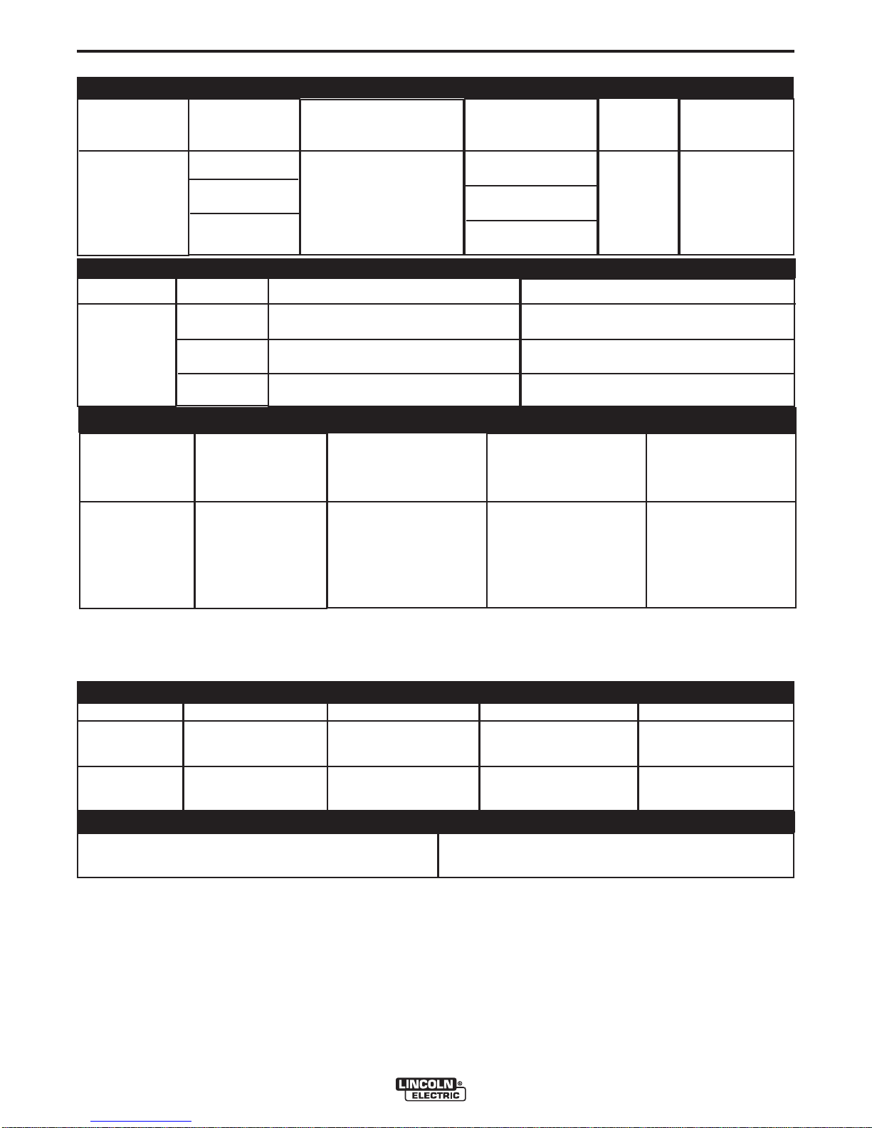
TECHNICAL SPECIFICATIONS - POWER WAVE® i400 (K2669-1, K2673-1)
INPUT AT RATED OUTPUT - THREE PHASE ONLY
Model
K2669-1
K2673-1
(Chassis Only)
Process
Duty Cycle
40% rating
60% rating
100% rating
Duty Cycle
Input Voltage ± 10%
208†/230/380*/460/575
3 phase 50/60 Hz
† includes 200V to 208V)
(
(* includes 380V to 415V)
RATED OUTPUT
Volts at Rated Amperes
Input Amperes
(incl. robot and
aux. load)
54/49/28/25/20
(73/66/38/33/26)
50/45/26/23/18
(69/62/36/31/25)
40/37/21/18/15
(59/54/31/27/21)
Idle Power
475 Watts
Max.
(fan on)
Amperes
Power Factor @
Rated Output
A-1
.95
40%
GMAW
GMAW-Pulse
FCAW
GTAW-DC
60%
100%
RECOMMENDED INPUT WIRE AND FUSE SIZES
3 PHASE INPUT
VOLTAGE
50/60Hz
208
230
380
460
575
1
Wire and Fuse Sizes based upon the U.S. National Electric Code and maximum output for 40°C (104°) ambient.
2
Also called “inverse time” or “thermal/magnetic” circuit breakers; circuit breakers that have a delay in tripping action that decreases as the
magnitude of current increases.
Input
Amperes
(incl. robot and
aux. load)
54 (73)
49 (66)
28 (38)
25 (33)
20 (26)
35
34
31.5
Type 75°C Copper
Wire in Conduit
AWG (mm
4 (25)
4 (25)
8 (10)
8 (10)
10 (6)
2
)
1
COPPER GROUNDING
CONDUCTOR
AWG (mm
8 (10)
8 (10)
10 (6)
10 (6)
10 (6)
2
)
420
400
350
Fuse (Super Lag) or
Breaker Size
80
70
50
40
30
PHYSICAL DIMENSIONS
MODEL
HEIGHT
WIDTH
DEPTH
WEIGHT
2
K2669-1
K2673-1
OPERATING TEMPERATURE RANGE
22.7 in. (577 mm)
21.0 in. (533 mm)
14°F to 104°F (-10C to 40C)
24.4 in. (620 mm)
22.6 in. (574 mm)
21.5 in. (546 mm)
18.5 in. (470 mm)
TEMPERATURE RANGES
STORAGE TEMPERATURE RANGE
-40°F to 185°F(-40°C to 85°C)
POWER WAVE® i400
209 lbs. (95 kg.)
147 lbs. (66.8 kg.)
A-2
INSTALLATION
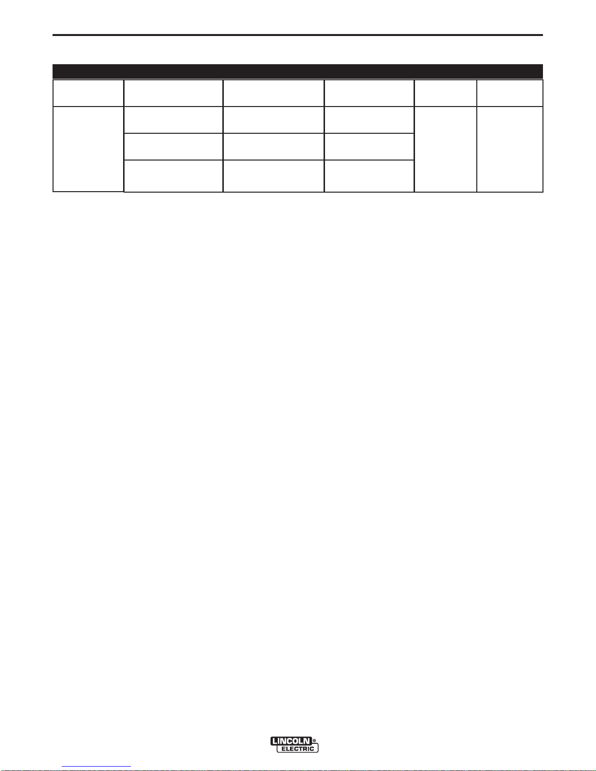
TECHNICAL SPECIFICATIONS - POWER WAVE® i400 (K2669-1, K2673-1)
REGULATORY REQUIREMENTS
MODEL
Market
Europe
Conformity Mark
4
CE
C-Tick
Standard
EN 60974-1
EN 50199
K2669-1
K2673-1
3
(Chassis Only)
China
US and Canada
CCC
CSA
C/UL
GB15579-1995
C22.2 No. 60
UL551
3
Chassis ratings applicable only when installed as a replacement in the POWER WAVE® i400 cabinet.
4
K2670-[ ] CE Filter Kit is required to meet CE and C-Tick conducted emission requirements.
Enclosure
Rating
IP21S
A-2
Insulation
Class
Class F
(155°C)
POWER WAVE® i400
A-3
INSTALLATION
SAFETY PRECAUTIONS
Read this entire installation section before you
start installation.
WARNING
ELECTRIC SHOCK can kill.
• Only qualified personnel should perform this installation.
• Turn the input power OFF at the disconnect switch or fuse box before
working on this equipment. Turn off
the input power to any other equipment connected to the welding system at the disconnect switch or fuse
box before working on the equipment.
• Do not touch electrically hot parts.
• Always connect the POWER WAVE® grounding
lug (located inside the reconnect input access
door) to a proper safety (Earth) ground.
-------------------------------------------------------------
LOCATION AND MOUNTING
The POWER WAVE® i400 case is designed to support the Fanuc R30iA controller and op box (up to
300lbs), matching the controller’s footprint and styling.
Mounting is externally accessible for simplified integration. The flexibility of the POWER WAVE® i400
also allows it to be operated as a stand alone unit. In
either case, bolting the unit to the floor or a suitable
platform is recommended to provide maximum stability.The minimum recommended clearance for chassis
removal is 26” (66cm) from the rear of the machine as
viewed from the output studs. See the Chassis
Removal Procedure for additional information.
CAUTION
• DO NOT MOUNT OVER COMBUSTIBLE SURFACES.
Where there is a combustible surface directly
under stationary or fixed electrical equipment,
that surface shall be covered with a steel plate at
least .06”(1.6mm) thick, which shall extend not
less than 5.90”(150mm) beyond the equipment
on all sides.
-----------------------------------------------------------------------
ENVIRONMENTAL CONSIDERATIONS
The POWER WAVE® i400 will operate in harsh environments. Even so, it is important that simple preventative measures are followed in order to assure long
life and reliable operation.
A-3
• Dirt and dust that can be drawn into the POWER
WAVE® i400 should be kept to a minimum. The
use of air filters on the air intake is not recommended because normal air flow may be restricted.
Failure to observe these precautions can result in
excessive operating temperatures and nuisance
shutdown.
• Do not use the POWER WAVE® i400 in an outdoor
environment. The power source should not be subjected to falling water, nor should any parts of it be
submerged in water. Doing so may cause improper
operation as well as pose a safety hazard. The
best practice is to keep the machine in a dry, sheltered area.
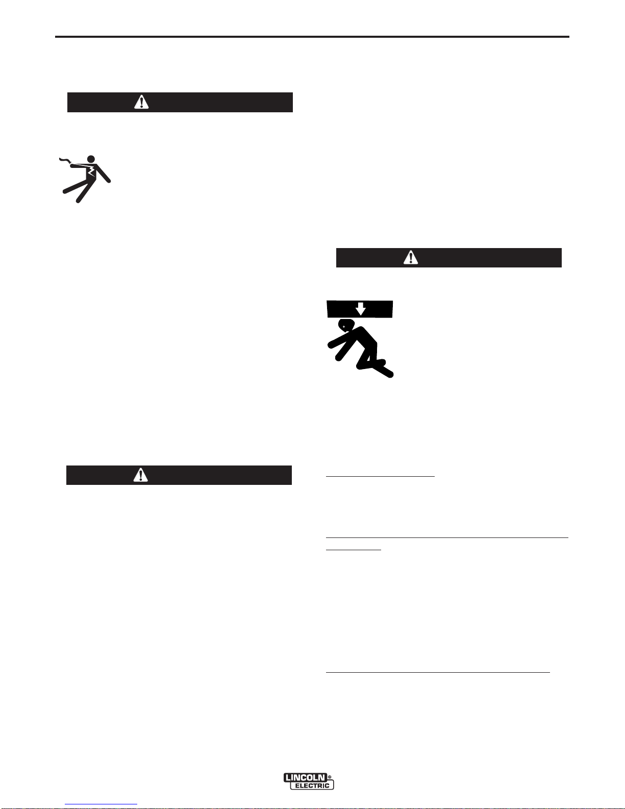
LIFTING
WARNING
• Lift only with equipment of adequate lifting capacity.
• Be sure machine is stable when
lifting.
• Do not lift this machine using lift
bail if it is equipped with a heavy
accessory such as trailer or gas
cylinder.
FALLING • Do not lift machine if lift bail is
EQUIPMENT can damaged.
cause injury. • Do not operate machine while
suspended from lift bail.
----------------------------------------------------------------------POWER WAVE® i400:
ner mounted lift bails only. Do not attempt to lift the
POWER WAVE® i400 with accessories attached to
it.
POWER WAVE® i400 with the Fanuc R30iA
Controller: When properly mounted the complete
integrated unit (power source and controller) can be
lifted using the lift hooks provided on the Fanuc
R30iA controller. Consult the Fanuc instruction manual for details and precautions.
NOTE: The POWER WAVE® i400 external corner
mounted lift bales must be removed when
mounted to the Fanuc R30iA controller.
Lift the machine by the cor-
• The POWER WAVE® i400 must be located where
there is free circulation of clean air such that air
movement in the louvered sections of the machine
will not be restricted.
POWER WAVE® i400 Replacement Chassis:
the chassis by the lift bail on top of the harmonic filter
assembly.
STACKING
The POWER WAVE® i400 cannot be stacked.
POWER WAVE® i400
Lift
A-4
INSTALLATION
A-4
ELECTROMAGNETIC COMPATIBILITY (EMC)
The EMC classification of the POWER WAVE® i400 is
Industrial, Scientific and Medical (ISM) group 2, class A. The
POWER WAVE® i400 is for industrial use only. (See prints
L10093-1, -2 Safety Pages in the front of Instruction Manual
for further details).
Locate the POWER WAVE® i400 away from radio controlled machinery. The normal operation of the POWER
WAVE® i400 may adversely affect the operation of RF controlled equipment, which may result in bodily injury or damage to the equipment.
INPUT AND GROUNDING CONNECTIONS
MACHINE GROUNDING
The frame of the welder must be
grounded. A ground terminal marked with the symbol
shown is located inside the reconnect/input access door for
this purpose. See your local and national electrical codes
for proper grounding methods.
INPUT CONNECTIONS
WARNING
ELECTRIC SHOCK can kill.
• Only a qualified electrician should
connect the input leads to the POWER
WAVE®. Connections should be made
in accordance with all local and
National Electrical Codes and the connection diagram located on the inside
of the reconnect / input access door
of the machine. Failure to do so may
result in bodily injury or death.
--------------------------------------------------------------------------------
Use a three-phase supply line. A 1.75 inch (45 mm) diameter access hole for the input supply is located on the case
back. Connect L1, L2, L3 and ground according to the input
supply and ground connection decals located near the input
power terminal block (1TB) and ground block inside of the
rear input reconnect box.
Input Fuse and Supply Wire Considerations
Refer to Specification in Installation Section for recommended fuse, wire sizes and type of the copper wires. Fuse the
input circuit with the recommended super lag fuse or delay
type breakers (also called "inverse time" or "thermal/magnetic" circuit breakers).
Choose input and grounding wire size according to local or
national electrical codes. Using input wire sizes, fuses or
circuit breakers smaller than recommended may result in
"nuisance" shut-offs from welder inrush currents, even if the
machine is not being used at high currents.
Input Voltage Selection
(See Figure A.1)
The POWER WAVE® i400 is shipped connected for the
highest input voltage listed on the rating plate. To move this
connection to a different input voltage, see the diagram
located on the inside of the reconnect access door, also
illustrated below. If the Auxiliary lead (indicated as ‘A’) is
placed in the wrong position, there are two possible results.
If the lead is placed in a position higher than the applied line
voltage, the welder may not come on at all. If the Auxiliary
lead is placed in a position lower than the applied line voltage, the welder will not come on, and the fuse located in the
reconnect area will open. If this occurs, turn off the input
voltage, properly connect the auxiliary lead, replace the
fuse, and try again.
Power Supply Connection for the Fanuc R30iA
Controller
The POWER WAVE® i400 is equipped with a dedicated
robot power terminal block (4TB) specifically designed to
feed input power directly to the Fanuc R30iA controller
through the power source rotary ON/OFF switch. The
K2677-1 Integration kit provides the proper cable and installations instructions to make this connection.
WARNING
The POWER WAVE® i400 on/off switch is not intended
as a service disconnect for this equipment. Only a qualified electrician should connect the input leads to the
POWER WAVE®. Connections should be made in
accordance with all local and national electrical codes
and the connection diagram located on the inside of the
reconnect access door of the machine. Failure to do so
may result in bodily injury or death.
Do not attempt to back feed input power though the
robot power terminal block (4TB) into the POWER
WAVE® i400. This is not its intended purpose and may
result in machine damage, bodily injury or death.
--------------------------------------------------------------------------------
POWER WAVE® i400

A-5
INSTALLATION
FIGURE A.1
Reconnect Diagram for K2669-1 POWER WAVE® i400
A-5
POWER WAVE® i400

A-6
INSTALLATION
CONNECTION DIAGRAMS AND SYSTEM
RECOMMENDED EQUIPMENT
System
Identifier
Power Source
Part No.
K2669-1
POWER WAVE® i400 Power Source
(includes S26064 POWER WAVE® Utilities CD)
A-6
Description
Integration Kit
Wire Drive
Power Source
to Wire Drive
Control Cable
Weld Cables
Robot Arm
Robot Controller
Torch
1
Maximum length 100 ft.(30.5 m) Cannot be connected end to end.
K2677-1
K2685-2
K1785-xx
K2163-xx
-or-
K1842-xx
Kxxxx
Kxxxx
Kxxxx
Integration Kit for Fanuc R30iA Controller. Includes industrial ethernet cable, power
cable, protective grommets, mounting plate, and dust proof strain relief.
1
See Price Book for details and bulk cable availability.
OPTIONAL EQUIPMENT
System
Identifier
Sense Lead Kit
Part No.
K940-xx
Remote Sense Lead Kit. Recommended for sensitive or critical applications to more accurately monitor the
arc voltage.
AutoDrive 4R90 Wire Drive
Feeder Control Cable (14 pin).
Welding Power Cables
Power Source to Wire Drive,
and Power Source to Work
K2163 Series cables sold in pairs.
K1842 Series cables sold individually.
Consult Automation Division
Description
DeviceNet Kit
Sync-Tandem Kit
CE Filter Kit
ArcLink Digital
Communication
Cable
External Ethernet
Network Equipment
DeviceNet Cables
and Accessories
2
Cables can be connected end to end to extend length (recommended maximum 200 ft [61.0m]).
K2780-1
K2781-1
K2670-1
K1543-xx
K2683-xx
Consult
Automation
Division
Customer
Supplied
DeviceNet Kit. Allows Power Wave i400 to communicate via DeviceNet protocol.
Sync-Tandem Kit. Allows two Power Wave i400s to perform synchronized tandem pulse welding. Includes all
necessary harnesses and cabling for 2 machines. Also provides access to special Sync-Tandem welding software.
CE Filter Kit. Required to meet CE and C-Tick conducted emission requirements. Input voltage limited to
380-415/3/50/60 with kit installed
2
ArcLink Control Cable (5 pin). Required for earlier controllers communicating via traditional ArcLink® over a
standard 2 wire CAN based network.
2
K2683 Recommended on Sever Duty application.
Ethernet Switch, Cables, etc. Required for external Ethernet system connectivity typically associated with
multiple arm or multiple power source applications.
DeviceNet Cables, Tees, and Terminators (5 pin sealed "mini style") Typically required for PLC or earlier
model controllers communicating via DeviceNet.
For additional information refer to the “DeviceNet Cable Planning and Installation Manual” (Allen Bradley publication DN-6.7.2).
POWER WAVE® i400

A-7
System
Identifier
Part No.
K1796-xx
INSTALLATION
A-7
OPTIONAL EQUIPMENT
Description
Coax Cable. Recommended to minimize the effects of the weld cable loop inductance and maximize perfor-
mance in critical high speed pulse applications.
Coaxial Weld Cable
External Dress
Cable for Robot
Arm
Personal Computer
Replacement
Chassis
K2593-xx
K2709-xx
Customer
Supplied
K2673-1
Note: K1796 coaxial cable is equivalent to 1/0 standard cable. K2539 coaxial cable is equivalent to AWG #1
standard cable. Connecting coaxial cables in parallel to increase current carrying capacity can significantly
reduce their inductance minimizing properties, and is therefore NOT RECOMMENDED. Consult the Output
Cable Guidelines for further information.
External Dress Cable. Heavy duty externally mounted 14pin wire feeder cable for use with robot arms not
equipped with an integral cable.
IBM Compatible PC (Windows NT SP6, Windows 2000, Windows XP, or greater) required for use with all
POWER WAVE® Utilities
POWER WAVE® i400 Replacement Chassis. Complete inverter power section. Intended only as a replacement to be installed in the POWER WAVE® i400 cabinet (includes S26064 POWER WAVE® Utilities CD).
POWER WAVE i400
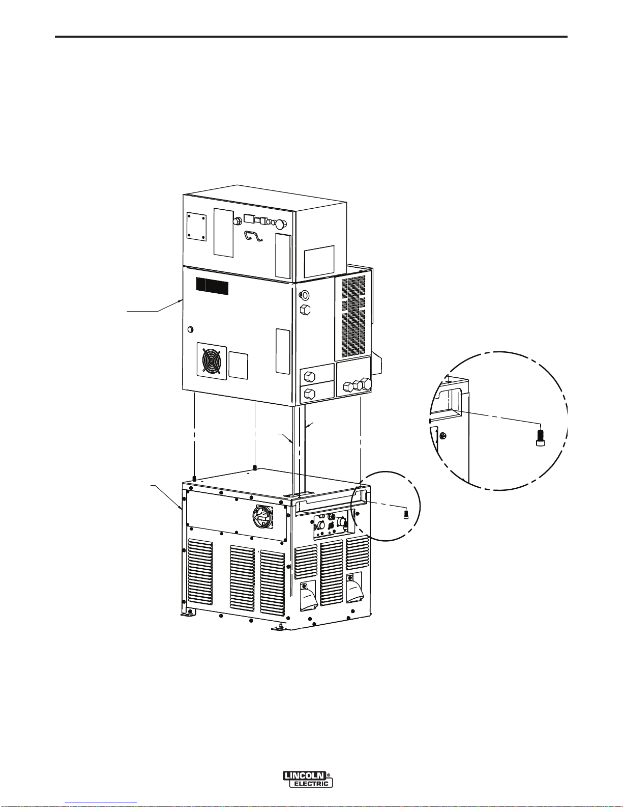
A-8
FANUC R30iA CONTROLLER MOUNTING
FANUC Robotics R-30iA
"a-cabinet" Controller
with Integrated Op Box
Power Wave i400
K2669-1
* ArcLink XT
Ethernet cable
* Power
cable
DETAIL A
A
* Refer to Output Cab le gu ideli nes for recommended cable size in PowerWave i400 Instruction Manual.
** Refer to Intergration kit K2677-1 instruct ion sheet
**
O
R
INSTALLATION
A-8
POWER WAVE® i400
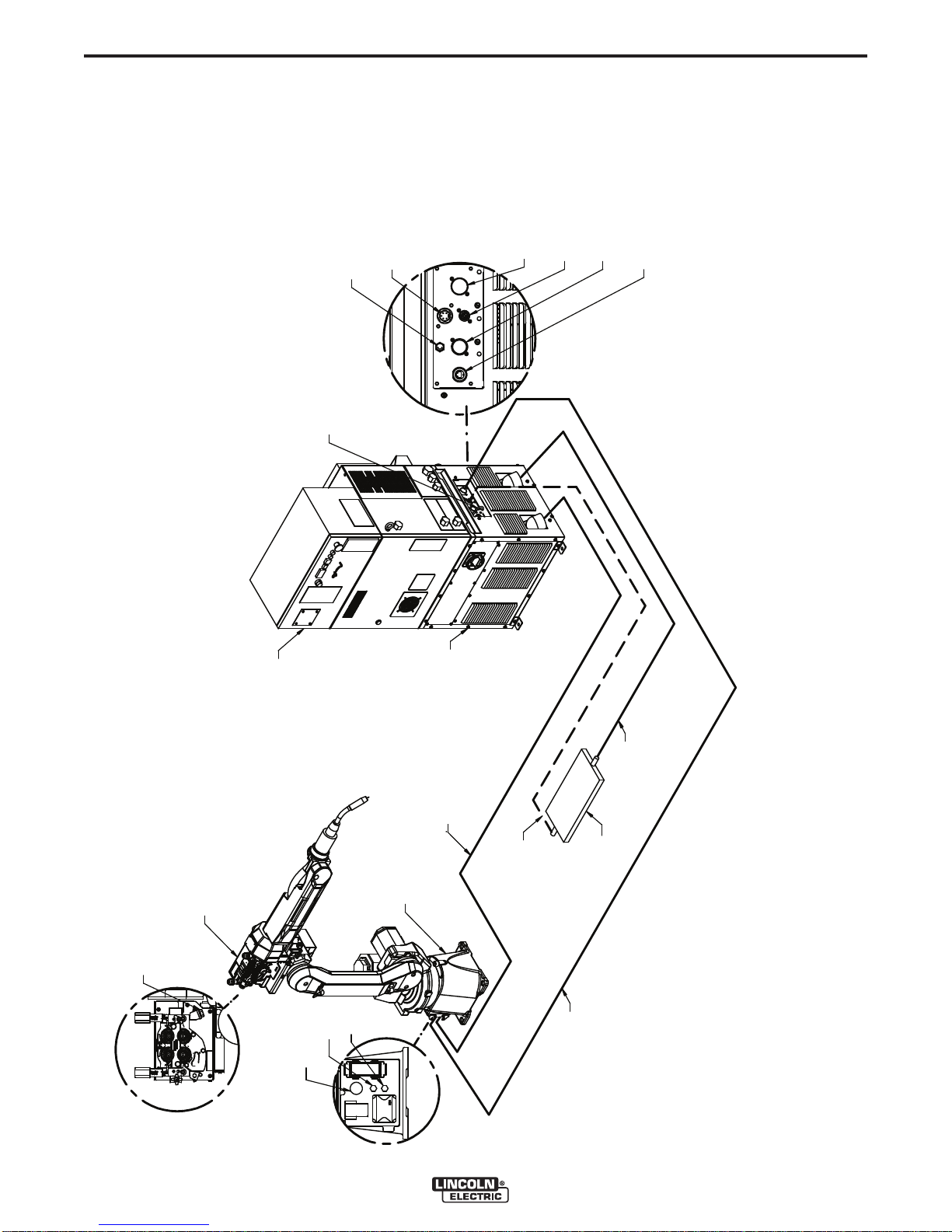
A-9
TYPICAL INTEGRATED SYSTEMS (SINGLE ARM)
ArcLink XT
Ethernet Connection
Voltage Sense
Connector
Wire Feeder
Connector
Power Wave i400
K2669-1
Optional Work
Sense Lead (21)
Wire Feeder
Control Cable
K1785-XX
ArcLink XT
Ethernet Cable
(Internal)
* Electrode
Cable (+)
K2163-xx or
K1842-xx
* Refer to Output Cable Guidelines for recommended
cable size in PowerWave i400 Instruction Manual.
Wire Feeder
Gas
Electrode
Connection
ARC Mate 1XXiC
Work
Piece
FANUC Robotics R-30iA
"a-cabinet" Controller
with Integrated Op Box
Air
* Work
Cable (-)
K2163-xx or
K1842-xx
ArcLink
Connector
Devicenet
Connector
Circuit Breaker
(15 Amp)
R
O
AutoDrive 4R90
K2685-2
INSTALLATION
A-9
POWER WAVE® i400
 Loading...