

Lincoln Electric POWER WAVE C300 CE Operator's Manual
IM2033
04/2010
Rev. 0
POWER WAVE C300 CE
OPERATOR’S MANUAL
ENGLISH
THE LINCOLN ELECTRIC COMPANY
22801 St. Clair Ave., Cleveland Ohio 44117-1199 USA
www.lincolnelectric.eu

English English
I
THE LINCOLN ELECTRIC COMPANY
EC DECLARATION OF CONFORMITY
Manufacturer and technical
documentation holder:
The Lincoln Electric Company
Address:
22801 St. Clair Ave.
Cleveland Ohio 44117-1199 USA
EC Company:
Lincoln Electric Europe S.L.
Address:
c/o Balmes, 89 - 80 2a
08008 Barcelona SPAIN
Hereby declare that welding equipment: Power Wave C300 CE, including options and accessories
Sales code:
K2865, code may also contain prefixes and suffixes
Is in conformity with Council Directives
and amendments:
EMC Directive 2004/108/EC
Low Voltage Directive 2006/95/EC
Standards: EN 60974-1, Arc Welding Equipment – Part 1: Welding Power
Sources, 2005
EN 60974-10 Arc Welding Equipment – Part 10: Electromagnetic
compatibility (EMC) requirements, 2003
Frank Stupczy,
Manufacturer
Dario Gatti,
European Community Representative
Compliance Engineering Manager European Engineering Director Machines
18 March 2010 19 March 2010
MCD234

English English
II
12/05
THANKS!
For having choosen the QUALITY of the Lincoln Electric products.
• Please Examine Package and Equipment for Damage. Claims for material damaged in shipment must be notified
immediately to the dealer.
• For future reference record in the table below your equipment identification information. Model Name, Code &
Serial Number can be found on the machine rating plate.
Model Name:
………………...…………………………….…………………………………………………………………………………………..
Code & Serial number:
………………….………………………………………………..
…………………………………………………….……………..
Date & Where Purchased:
…………………………………………………………………...
……………………….…………………………………………..
ENGLISH INDEX
Safety .............................................................................................................................................................................. 1
Installation and Operator Instructions .............................................................................................................................. 2
Electromagnetic Compatibility (EMC) ............................................................................................................................ 13
Technical Specifications .................................................................................................................................................. 1
WEEE .............................................................................................................................................................................. 1
Spare Parts ...................................................................................................................................................................... 2
Electrical Schematic ........................................................................................................................................................ 2
Accessories ..................................................................................................................................................................... 2
English English
1
Safety
11/04
WARNING
This equipment must be used by qualified personnel. Be sure that all installation, operation, maintenance and repair
procedures are performed only by qualified person. Read and understand this manual before operating this equipment.
Failure to follow the instructions in this manual could cause serious personal injury, loss of life, or damage to this
equipment. Read and understand the following explanations of the warning symbols. Lincoln Electric is not responsible
for damages caused by improper installation, improper care or abnormal operation.
WARNING: This symbol indicates that instructions must be followed to avoid serious personal injury,
loss of life, or damage to this equipment. Protect yourself and others from possible serious injury or
death.
READ AND UNDERSTAND INSTRUCTIONS: Read and understand this manual before operating
this equipment. Arc welding can be hazardous. Failure to follow the instructions in this manual could
cause serious personal injury, loss of life, or damage to this equipment.
ELECTRIC SHOCK CAN KILL: Welding equipment generates high voltages. Do not touch the
electrode, work clamp, or connected work pieces when this equipment is on. Insulate yourself from
the electrode, work clamp, and connected work pieces.
ELECTRICALLY POWERED EQUIPMENT: Turn off input power using the disconnect switch at the
fuse box before working on this equipment. Ground this equipment in accordance with local electrical
regulations.
ELECTRICALLY POWERED EQUIPMENT: Regularly inspect the input, electrode, and work clamp
cables. If any insulation damage exists replace the cable immediately. Do not place the electrode
holder directly on the welding table or any other surface in contact with the work clamp to avoid the
risk of accidental arc ignition.
ELECTRIC AND MAGNETIC FIELDS MAY BE DANGEROUS: Electric current flowing through any
conductor creates electric and magnetic fields (EMF). EMF fields may interfere with some
pacemakers, and welders having a pacemaker shall consult their physician before operating this
equipment.
CE COMPLIANCE: This equipment complies with the European Community Directives.
FUMES AND GASES CAN BE DANGEROUS: Welding may produce fumes and gases hazardous to
health. Avoid breathing these fumes and gases. To avoid these dangers the operator must use
enough ventilation or exhaust to keep fumes and gases away from the breathing zone.
ARC RAYS CAN BURN: Use a shield with the proper filter and cover plates to protect your eyes from
sparks and the rays of the arc when welding or observing. Use suitable clothing made from durable
flame-resistant material to protect you skin and that of your helpers. Protect other nearby personnel
with suitable, non-flammable screening and warn them not to watch the arc nor expose themselves to
the arc.
WELDING SPARKS CAN CAUSE FIRE OR EXPLOSION: Remove fire hazards from the welding
area and have a fire extinguisher readily available. Welding sparks and hot materials from the welding
process can easily go through small cracks and openings to adjacent areas. Do not weld on any
tanks, drums, containers, or material until the proper steps have been taken to insure that no
flammable or toxic vapors will be present. Never operate this equipment when flammable gases,
vapors or liquid combustibles are present.
WELDED MATERIALS CAN BURN: Welding generates a large amount of heat. Hot surfaces and
materials in work area can cause serious burns. Use gloves and pliers when touching or moving
materials in the work area.
SAFETY MARK: This equipment is suitable for supplying power for welding operations carried out in
an environment with increased hazard of electric shock.
English English
2
CYLINDER MAY EXPLODE IF DAMAGED: Use only compressed gas cylinders containing the
correct shielding gas for the process used and properly operating regulators designed for the gas and
pressure used. Always keep cylinders in an upright position securely chained to a fixed support. Do
not move or transport gas cylinders with the protection cap removed. Do not allow the electrode,
electrode holder, work clamp or any other electrically live part to touch a gas cylinder. Gas cylinders
must be located away from areas where they may be subjected to physical damage or the welding
process including sparks and heat sources.
NOISE APPEARES DURING WELDING CAN BE HARMFUL: Welding arc can cause noise with high
level of 85dB for 8-hour week day. Welders operating welding machines are obligated to wear the
proper ear protectors /appendix No. 2 for the Decree of the Secretary of Labor and Social Policy from
17.06 1998 – Dz.U. No. 79 pos. 513/. According to the Decree the Secretary of Health and Social
Welfare from 09.07.1996 /Dz.U. No. 68 pos. 194/, employers are obligated to carry examinations and
measurements of health harmful factors.
MOVING PARTS ARE DANGEROUS: There are moving mechanical parts in this machine, which
can cause serious injury. Keep your hands, body and clothing away from those parts during machine
starting, operating and servicing.
Installation and Operator Instructions
Read this entire section before installation or operation
of the machine.
Location and Environment
THE POWER WAVE® C300CE will operate in harsh
environments. Even so, it is important that simple
preventative measures are followed in order to assure
long life and reliable operation.
• The machine must be located where there is free
circulation of clean air such that air movement in the
back, out the sides and bottom will not be restricted.
• Dirt and dust that can be drawn into the machine
should be kept to a minimum. The use of air filters
on the air intake is not recommended because
normal air flow may be restricted. Failure to
observe these precautions can result in excessive
operating temperatures and nuisance shutdown.
• Keep machine dry. Shelter from rain and snow. Do
not place on wet ground or in puddles.
• Do not mount the POWER WAVE® C300 CE over
combustible surfaces. Where there is a combustible
surface directly under stationary or fixed electrical
equipment, that surface shall be covered with a
steel plate at least 1.6mm thick, which shall extend
not less than 150mm beyond the equipment on all
sides.
Lifting
WARNING
FALLING EQUIPMENT can cause injury.
Lift only with equipment of adequate lifting capacity.
• Be sure machine is stable when lifting.
• Do not operate machine while suspended when
lifting.
Both handles should be used when lifting POWER
WAVE® C300 CE. When using a crane or overhead
device a lifting strap should be connected to both
handles. Do not attempt to lift the POWER WAVE
®
C300 CE with accessories attached to it.
Stacking
The POWER WAVE® C300 CE cannot be stacked.
Tilting
Place the machine directly on a secure, level surface or
on a recommended undercarriage. The machine may
topple over if this procedure is not followed.
Duty Cycle and Overheating
The POWER WAVE® C300 CE is rated at 250A - 26.5V
@ 100% duty cycle. It is further rated to provide 300A –
29V @ 40% duty cycle.
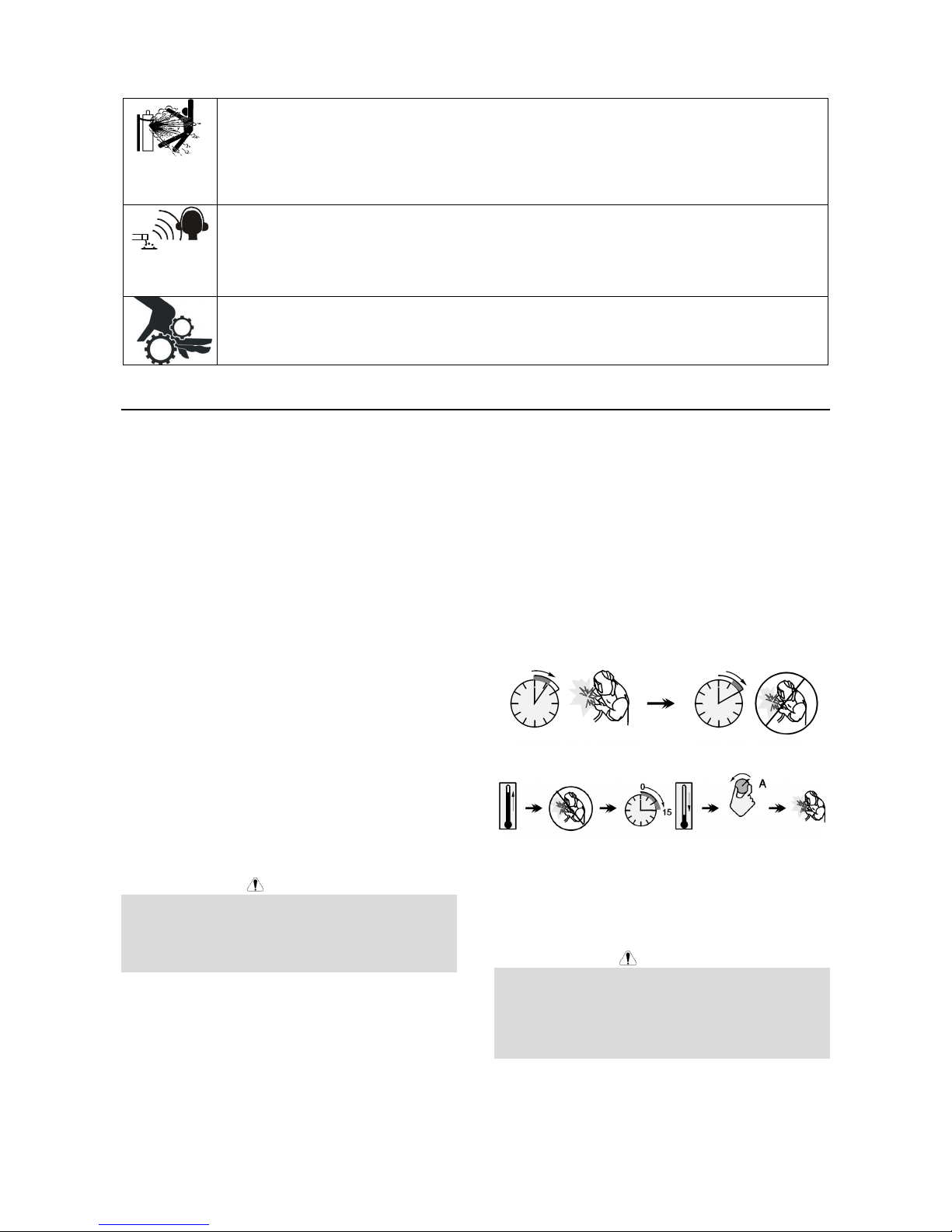
The duty cycle is based on a ten-minute period. A 40%
duty cycle represents 6 minutes of welding and 4
minutes of idling in a 10-minute period.
Example: 40% Duty Cycle:
Welding for 4 minutes. Break for 6 minutes.
Minutes or decrease
Duty Cycle
Preparation for Work
Input and Ground Connections
WARNING
Only a qualified electrician should connect the input
leads to the POWER WAVE® C300 CE. Connections
should be made in accordance with all local and national
electrical codes and the connection diagram located on
the inside of the reconnect access door of the machine.
Failure to do so may result in bodily injury or death.
Machine Grounding
The frame of the welder must be grounded. A ground
terminal marked with a ground symbol is located next to
the input power connection block. See your local and
English English
3
national electrical codes for proper grounding methods.
High Frequency Protection
The EMC classification of the POWER WAVE® C300 CE
is Industrial, Scientific and Medical (ISM) group 2, class
A. The POWER WAVE® C300 CE is for industrial use
only (see Electromagnetic Compatibility EMC Safety
Section).
Locate the POWER WAVE® C300 CE away from radio
controlled machinery. The normal operation of the
POWER WAVE® C300 CE may adversely affect the
operation of RF controlled equipment, which may result
in bodily injury or damage to the equipment.
Input Connection
• 4.6m power cord is provided and wired into the
machine.
• Single Phase Input - Not supported.
• Three Phase Input - Connect green/yellow lead to
ground per National Electric Code. Connect grey,
brown and black leads to power.
• The POWER WAVE® C300 CE automatically
adjusts to work with different input voltages. No
reconnect switches settings are required.
WARNING
The POWER WAVE® C300 CE ON/OFF switch is not
intended as a service disconnect for this equipment.
Power Cord Replacement
If the input power cord is damaged or needs to be
replaced an input power connection block is located in
the access panel under the wire spool.
WARNING
ALWAYS CONNECT THE POWER WAVE
GROUNDING LUG (LOCATED INSIDE THE ACCESS
PANEL) TO A PROPER SAFETY (EARTH) GROUND.
Shielding Gas Connection
Customer must provide a cylinder of shielding gas, a
pressure regulator, any flow control valve.
Connect a supply hose from the gas cylinder flow valve
outlet to the 5/8-18 female inert gas fitting on the back
panel of the POWER WAVE® C300 CE.
• MAXIMUM INLET PRESSURE IS 6.9 BAR.
Procedure to Install Drive Rolls and Wire
Guides
1. Turn power off at the welding power source.
2. Release the idle roll pressure arm.
3. Remove the outer wire guide by turning the knurled
thumbscrews counter-clockwise to unscrew them
from the feed plate.
4. Rotate the triangular lock and remove the drive rolls
(See Figure 1).
Unlocked position Locked position
Figure 1
5. Remove the inner wire guide.
6. Insert the new inner wire guide, groove side out,
over the two locating pins in the feed plate.
7. Install a drive roll on each hub assembly secure with
the triangular lock.
8. Install the outer wire guide by aligning it with the
pins and tightening the knurled thumbscrews.
9. Close the idle arm and engage the idle roll pressure
arm. Adjust the pressure appropriately.
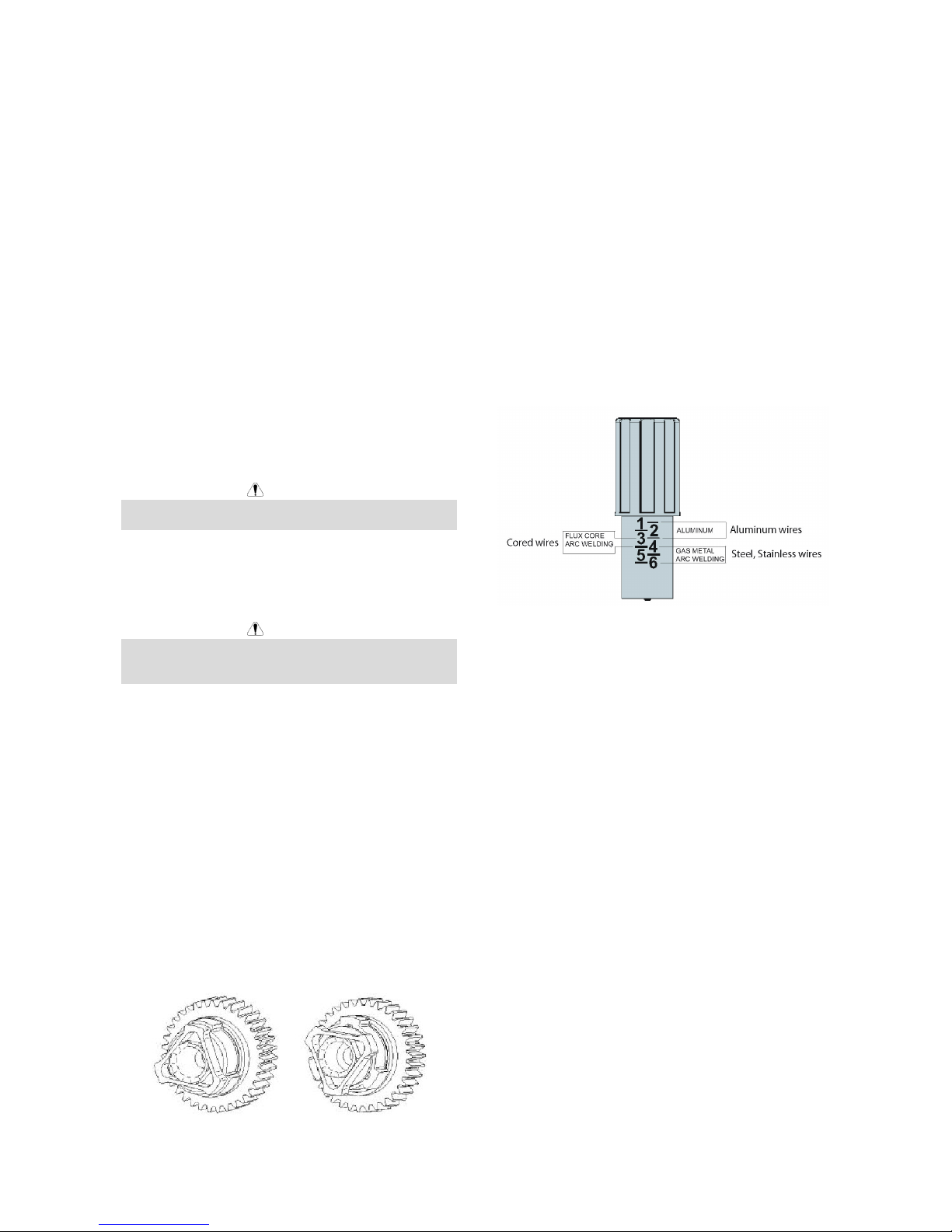
Pressure Arm Adjustment
The pressure arm controls the amount of force the drive
rolls exert on the wire. Proper adjustment of the
pressure arm gives the best welding performance.
Set the pressure arm as follows (see Fig A.3):
• Aluminum wires: between 1 and 3
• Cored wires: between 3 and 4
• Steel, Stainless wires: between 4 and 6
Figure 2
Operation – General
Power-up Sequence
When the POWER WAVE® C300 CE is powered it can
take as long as 30 seconds for the machine to be ready
to weld. During this time period the user interface will
not be active.
Product Description
The POWER WAVE® C300 CE is a high performance
multi-process machine with GMAW, FCAW, SMAW, DC
TIG, and pulse capability. It will offer a premier welding
performance solution for specific areas such as
aluminum, stainless, nickel where size and weight are an
issue.
The POWER WAVE® C300 CE will provide the
following:
• Power - 300A @ 40%, 250A @ 100%.
• Multi Input Voltage with no reconnect - 208-575V,
50-60 Hz input, 3Phase Power.
• < 95% Power factor – optimizes available electrical
capacity.
• Environmentally Hardened - IP23 rated for operating
in difficult environments.
• Ethernet connectivity – allows access to the Power
Wave utilities software tools.
• Line Voltage Compensation.
• ArcLink
®
platform.
• Electronic over current protection.
• Input over voltage protection.
• F.A.N. (fan as needed). Cooling fan runs when the
English English
4
output is energized 15 seconds following the strike
of the welding arc and will continue to run 5 minutes
following the end of the weld.
The following capabilities are supported:
• Push-pull (12-pin) connection - Panther™ and
Cougar™.
• Remote foot pedal or hand amptrol.
• Standard MIG gun trigger connection.
• Watercooler CoolArc 50.
WARNING
The POWER WAVE® C300 CE is not recommended for
pipe thawing.
Equipment Limitations
• Maximum spool size is 305mm diameter.
• Maximum spool weight is 20kg.
• Wire welding processes are limited to positive
polarity only.
• Does not operate on single phase power.
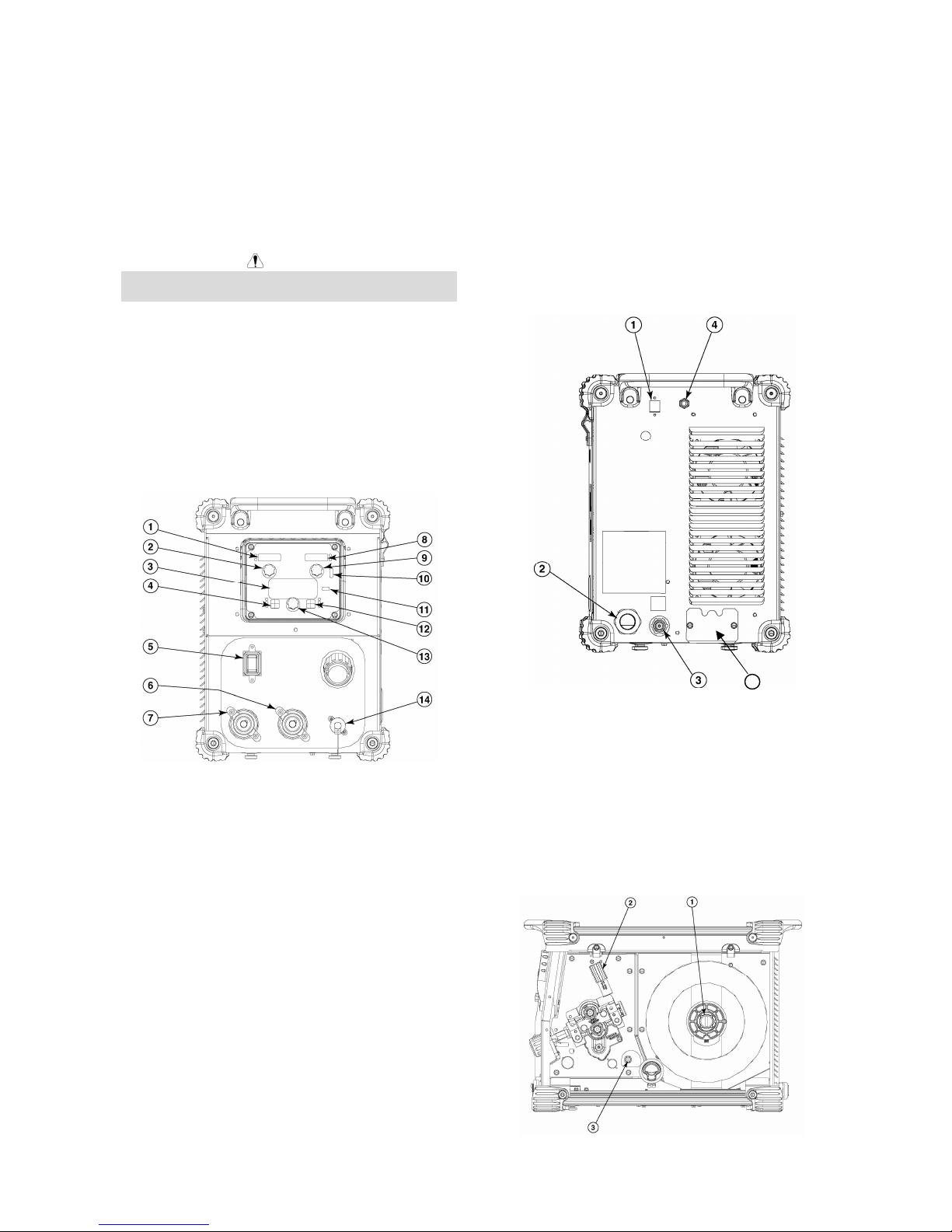
Case Front Controls
All operator controls and adjustments are located on the
case front of the Power Wave.
Figure 3
1. Left Display - Shows wire feed speed or amperage.
2. Left Knob - Adjusts value in left display.
3. Main Display - Shows detailed welding and
diagnostic information.
4. Left Button - Changes the Main display to show the
Weld Mode, Inductance or UltimArc™ Control or
Memories.
5. On/Off Switch - Controls power to the Power Wave
C300CE.
6. “+” Output Stud - Connection for electrode
positive.
7. “-” Output Stud - Connection for electrode
negative.
8. Right Display - Shows voltage or trim.
9. Right Knob - Adjusts value in right display.
10. Thermal Light - Indicates when machine has
thermal fault.
11. Set-Up - Lights when machine is in set-up mode.
12. Right Button - Changes the Main display to arc
start, arc end and trigger options.
13. MAIN KNOB - Changes the values on the Main
display.
14. 12-pin Connector - Connection for cross switch
gun, push pull guns, remotes.
Case Back Controls
Figure 4
1. Ethernet Connector
2. Power Cord
3. Gas Connection
4. Circuit Breaker
5. Cooler connections
Internal Controls
English English
5
Figure 5
1. Spindle Brake
2. Wire Drive Pressure Arm
3. Cold Inch / Gas Purge Switch
Definition of Welding Modes
Non-Synergic Welding Modes
• A Non-synergic welding mode requires all welding
process variables to be set by the operator.
Synergic Welding Modes
• A Synergic welding mode offers the simplicity of
single knob control. The machine will select the
correct voltage and amperage based on the wire
feed speed (WFS) set by the operator.
Basic Welding Controls Weld Mode
Selecting a weld mode determines the output
characteristics of the Power Wave power source. Weld
modes are developed with a specific electrode material,
electrode size, and shielding gas. For a more complete
description of the weld modes programmed into the
Power Wave at the factory, refer to the Weld Set
Reference Guide supplied with the machine or available
at www.powerwavesoftware.com.
Wire Feed Speed (WFS)
In synergic welding modes (synergic CV, GMAW-P),
WFS is the dominant control parameter. The user
adjusts WFS according to factors such as wire size,
penetration requirements, heat input, etc. The Power
Wave then uses the WFS setting to adjust the voltage
and current according to settings contained in the Power
Wave. In non-synergic modes, the WFS control
behaves like a conventional power source where WFS
and voltage are independent adjustments. Therefore, to
maintain proper arc characteristics, the operator must
adjust the voltage to compensate for any changes made
to the WFS.
Amps
In constant current modes, this control adjusts the
welding current.
Volts
In constant voltage modes, this control adjusts the
welding voltage.
Trim
In pulse synergic welding modes, the Trim setting
adjusts the arc length. Trim is adjustable from 0.50 to
1.50. 1.00 is the nominal setting and is a good starting
point for most conditions.
Inductance and UltimArcTM Control
UltimArcTM Control allows the operator to vary the arc
characteristics from “soft” to “crisp”. UltimArc™ Control
is adjustable from –10.0 to +10.0 with a nominal setting
of 0.0.
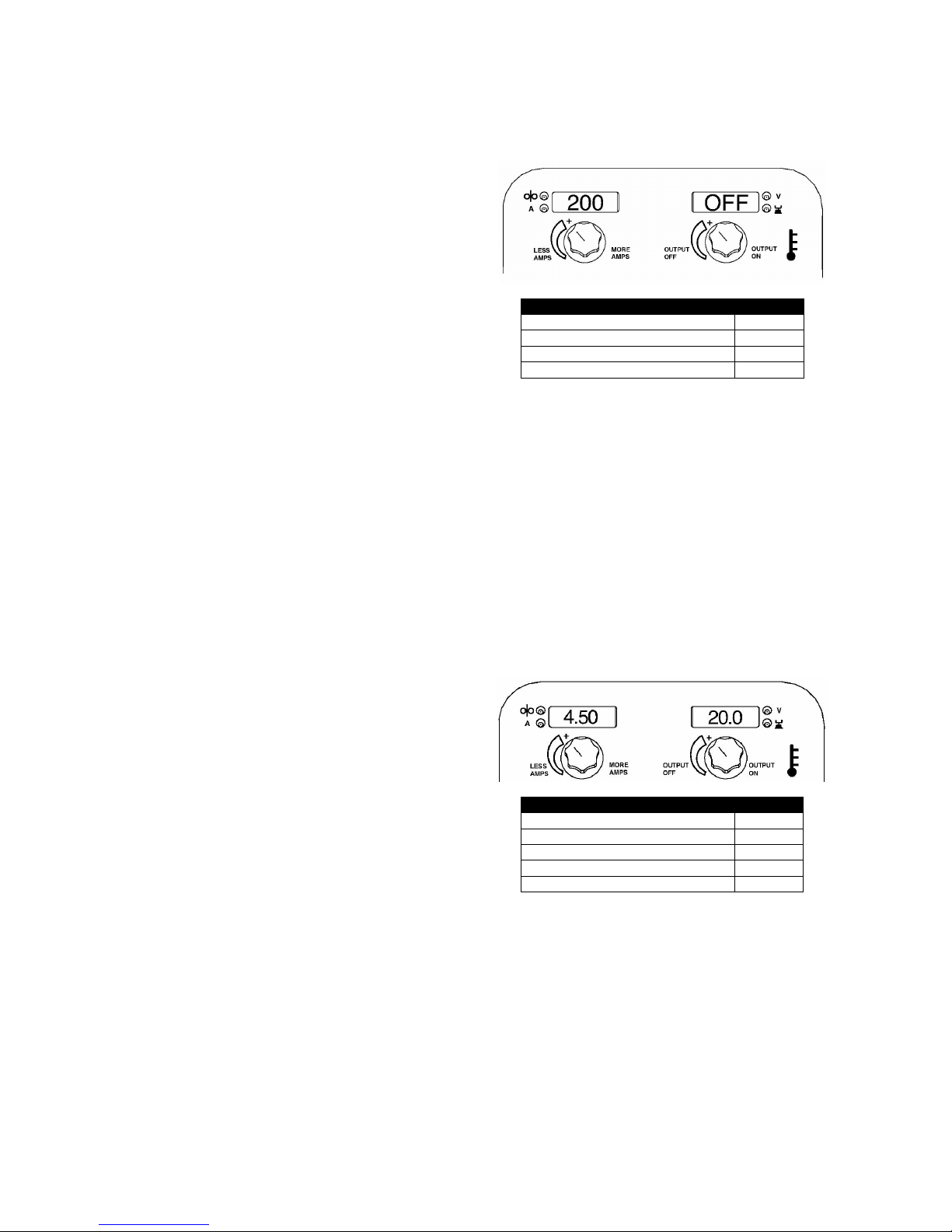
SMAW (Stick) Welding
SMAW is most often used for outdoor construction, pipe
welding and general repairs. The POWER WAVE®
C300 CE controls Amperage, Output Control and Arc
Force during SMAW welding.
During SMAW welding the wire drive remains idle.
Basic Operation
CC STICK MODE
Process
Mode
Stick Soft (7018) 1
Stick Crisp (6010) 2
Stick Pipe 4
Non-Synergic GMAW and FCAW
Welding
In non-synergic modes, the WFS control is similar to a
conventional CV power source where WFS and voltage
are independent adjustments. Therefore to maintain the
arc characteristics, the operator must adjust the voltage
to compensate for any changes made to the WFS.
UltimArc™ Control, adjusts the apparent inductance of
the wave shape. The UltimArc™ Control adjustment is
similar to the “pinch” function in that it is inversely
proportional to inductance. Therefore, increasing
UltimArc™ Control greater than 0.0 results in a crisper
arc (more spatter) while decreasing the UltimArc™
Control to less than 0.0 provides a softer arc (less
spatter).
Basic Operation
WELD MODE
Process
Mode
GMAW, STANDARD CV 5
GMAW, POWER MODE 40
FCAW, (SS) STANDARD CV 6
FCAW, (GS) STANDARD CV 7
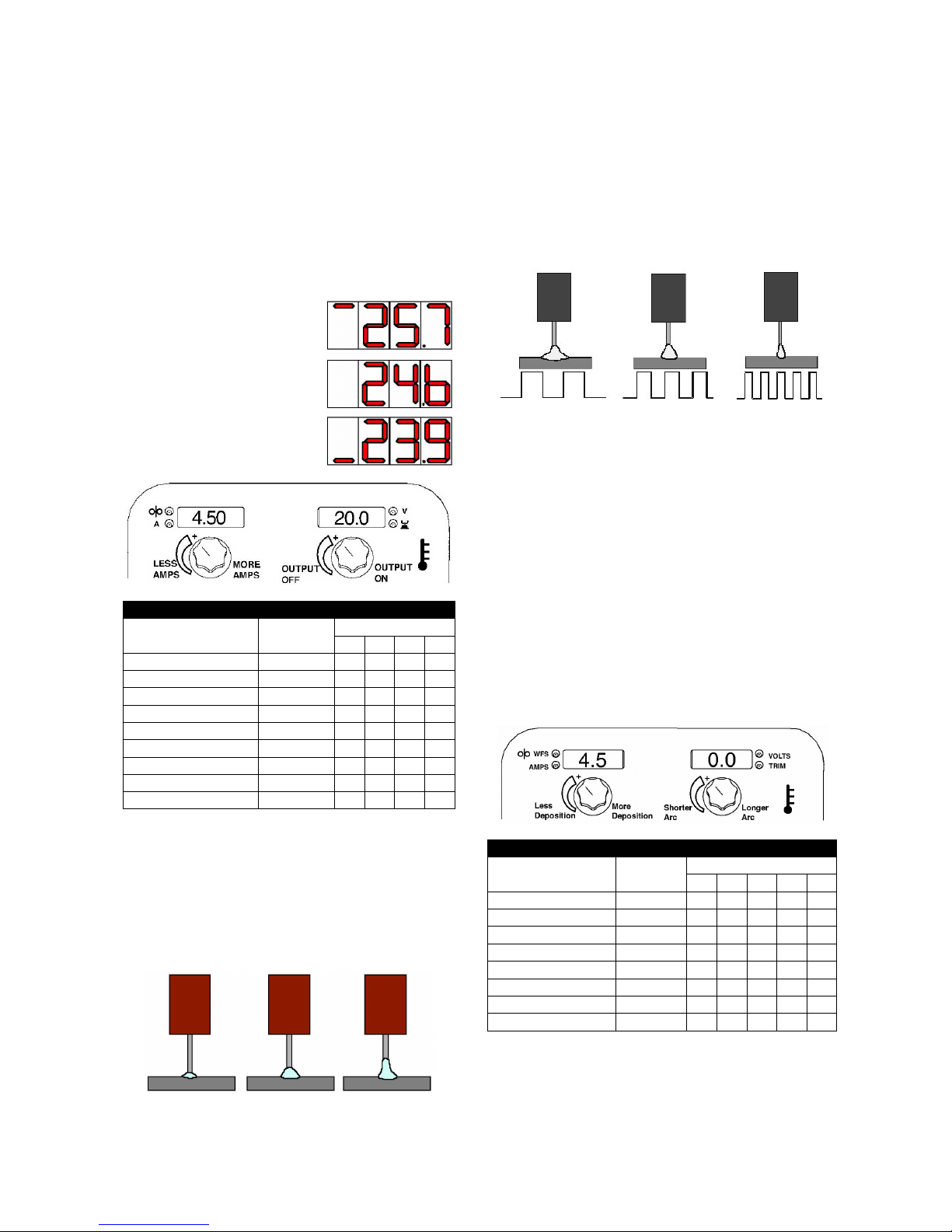
GMAW (MIG) Synergic Welding
In synergic welding modes, WFS is the dominant control
parameter. For each wire feed speed, a corresponding
voltage is programmed into the machine at the factory.
The user adjusts WFS according to factors such as wire
size, material thickness, penetration requirements, etc.
The Power Wave then uses the WFS setting to select
the appropriate voltage. The voltage selected will be a
nominal voltage. The user can adjust the voltage higher
or lower to compensate for material condition or
individual preference.
UltimArc™ Control, adjusts the apparent inductance of
the wave shape. The UltimArc™ Control adjustment is
similar to the “pinch” function in that it is inversely
English English
6
proportional to inductance. Therefore, increasing
UltimArc™ Control greater than 0.0 results in a crisper
arc (more spatter) while decreasing the UltimArc™
Control to less than 0.0 provides a softer arc (less
spatter).
Synergic CV programs feature an ideal voltage best
suited for most procedures. Use this voltage as a
starting point and adjust if needed for personal
preferences.
When the voltage knob is rotated, the display will show
an upper or lower bar indicating if the voltage is
above or below the ideal voltage.
• Preset voltage above ideal
voltage (upper bar
displayed).
• Preset voltage at ideal
voltage (no bar displayed).
• Preset voltage below ideal
voltage (lower bar
displayed).
Basic Operation
WELD MODE
Electrode Gas
Wire Size
0,8 0,9 1,0 1,2
Steel CO2 93 14 10 20
Steel ArMIX 94 15 11 21
Stainless ArCO2 61 - 31 41
Stainless Ar/He/CO2 63 - 33 43
Aluminum AlSi Ar - - - 71
Aluminum AlMg Ar - - 151 75
MetalCore ArMIX - - - 81
CordWire CO2 - - - 90
CordWire ArMIX - - - 91
Steel and Stainless Synergic GMAW-P
(Pulsed MIG)
Pulse welding modes are synergic; using wire feed
speed as the main control parameter. As the wire feed
speed is adjusted, the power source adjusts the
waveform parameters to maintain good welding
characteristics. Trim is used as a secondary control to
change the arc length for material conditions or
individual preference (see figure 6).
Trim .50
Arc Length
Short
Trim 1.00
Arc Length
Medium
Trim 1.50
Arc Length
Long
UltimArc™ Control
UltimArc™ Control adjusts the focus or shape of the arc.
UltimArc™ Control is adjustable from -10.0 to +10.0 with
a nominal setting of 0.0. Increasing the arc control
increases the pulse frequency and background current
while decreasing the peak current.
This results in a tight, stiff arc used for high speed sheet
metal welding. Decreasing the arc control decreases the
pulse frequency and background current while
increasing the peak current. This results in a soft arc
good for out of position welding.
Ultimate™
Control –10.0
Low frequency
Wide
Ultimate™
Control OFF
Medium frequency
and Width
Ultimate™
Control +10.0
High frequency
Focused
Figure 7
The Power Wave utilizes adaptive control to compensate
for changes in the electrical stick-out (distance from the
contact tip to the work piece) while welding. The Power
Wave waveforms are optimized for a 1,6 to 1,9mm stick
out depending on the wire type and wire feed speed.
The adaptive behaviour supports a range of stick outs
from approximately 1,27 to 3,1mm. At low or high wire
feed speeds, the adaptive range may be less due to
physical limitations of the welding process.
Steel and Stainless GMAW-P (Pulsed
MIG) Welding
Basic Operation
WELD MODE
Electrode Gas
Wire Size
0,8 0,9 1,0 1,2 1,4
Steel (Crisp) ArMIX 95 16 12 22 Steel (Rapid Arc) ArMIX - 17 13 18 Stainless ArCO2 66 - 36 46 Stainless Ar/He/CO2 64 - 34 44 MetalCore ArMIX - - 82 84
Ni Alloy 70Ar/30He - - - 175 Si Bronze Ar - - 192 - Copper ArHe - - 195 196 -
Figure 6.
 Loading...