

Page 1
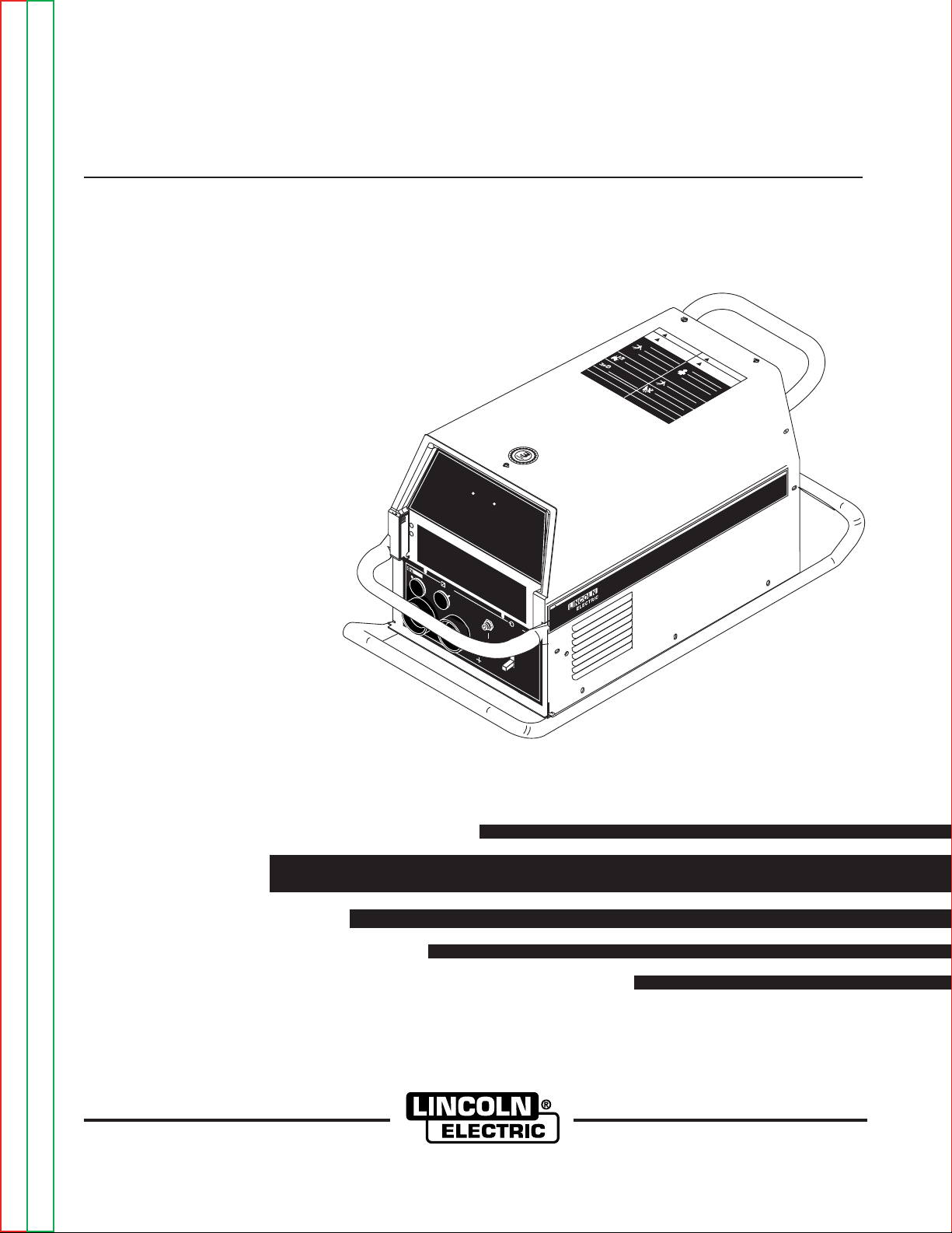
POWER WAVE 355M/405M
W
AR
N
I
N
G
WAR
N
I
N
G
A
VI
SO
D
E
PR
EC
A
U
C
I
O
N
A
T
T
EN
T
I
O
N
!
!
!
!
L
o
r
e
m
i
p
s
u
m
d
o
l
o
r
s
i
t
a
m
e
t
c
o
n
s
e
c
t
e
t
u
e
r
a
d
i
p
i
s
c
i
n
g
L
o
r
e
m
i
p
s
u
m
d
o
l
o
r
s
i
t
a
m
e
t
c
o
n
s
e
c
t
e
t
u
e
r
a
d
i
p
i
s
c
i
n
g
e
l
i
t
,
e
d
d
i
a
m
n
o
n
e
l
i
t
,
e
d
d
i
a
m
n
o
n
u
m
m
u
m
m
y
n
i
b
h
e
u
i
s
m
o
d
t
i
n
c
i
d
u
n
t
u
t
y
n
i
b
h
e
u
i
s
m
o
d
t
i
n
c
i
d
u
n
t
u
t
l
a
o
r
e
e
t
d
o
l
o
r
e
m
a
g
n
a
a
l
i
q
u
a
m
e
r
l
a
o
r
e
e
t
d
o
l
o
r
e
m
a
g
n
a
a
l
i
q
u
a
m
e
r
ata
t
L
o
r
e
m
i
p
s
u
m
d
o
l
o
r
s
i
t
a
m
e
t
c
o
n
s
e
c
t
e
t
u
e
r
a
d
i
p
i
s
c
i
n
g
L
o
r
e
m
i
p
s
u
m
d
o
l
o
r
s
i
t
a
m
e
t
c
o
n
s
e
c
t
e
t
u
e
r
a
d
i
p
i
s
c
i
n
g
e
l
i
t
,
e
d
d
i
a
m
n
o
n
e
l
i
t
,
e
d
d
i
a
m
n
o
n
u
m
m
u
m
m
y
n
i
b
h
e
u
i
s
m
o
d
t
i
n
c
i
d
u
n
t
u
t
y
n
i
b
h
e
u
i
s
m
o
d
t
i
n
c
i
d
u
n
t
u
t
l
a
o
r
e
e
t
d
o
l
o
r
e
m
a
g
n
a
a
l
i
q
u
a
m
e
r
l
a
o
r
e
e
t
d
o
l
o
r
e
m
a
g
n
a
a
l
i
q
u
a
m
e
r
ata
t
W
A
R
N
I
N
G
R
E
M
O
T
E
P
O
WE
R
O
F
F
O
N
P
O
W
E
R W
A V
E 3
5
5
RETURN TO MAIN MENU
For use with machine code numbers 11141, 11142
Safety Depends on You
Lincoln arc welding and cutting
equipment is designed and built
with safety in mind. However,
your overall safety can be
increased by proper installation
. . . and thoughtful operation on
your part. DO NOT INSTALL,
OPERATE OR REPAIR THIS
EQUIPMENT WITHOUT READING THIS MANUAL AND THE
SAFETY PRECAUTIONS CONTAINED THROUGHOUT. And,
most importantly, think before
you act and be careful.
SVM181-A
January, 2008
View Safety Info View Safety Info View Safety Info View Safety Info
Return to Master TOC Return to Master TOC Return to Master TOC Return to Master TOC
Cleveland, Ohio 44117-1199 U.S.A. TEL: 216.481.8100 FAX: 216.486.1751 WEB SITE: www.lincolnelectric.com
SERVICE MANUAL
Copyright © Lincoln Global Inc.
• World's Leader in Welding and Cutting Products •
• Sales and Service through Subsidiaries and Distributors Worldwide •
Page 2
i i
SAFETY
WARNING
CALIFORNIA PROPOSITION 65 WARNINGS
Diesel engine exhaust and some of its constituents
are known to the State of California to cause cancer, birth defects, and other reproductive harm.
The Above For Diesel Engines
ARC WELDING can be hazardous. PROTECT YOURSELF AND OTHERS FROM POSSIBLE SERIOUS INJURY OR DEATH.
KEEP CHILDREN AWAY. PACEMAKER WEARERS SHOULD CONSULT WITH THEIR DOCTOR BEFORE OPERATING.
Read and understand the following safety highlights. For additional safety information, it is strongly recommended that you purchase a copy of “Safety in Welding & Cutting - ANSI Standard Z49.1” from the American Welding Society, P.O. Box 351040,
Miami, Florida 33135 or CSA Standard W117.2-1974. A Free copy of “Arc Welding Safety” booklet E205 is available from the
Lincoln Electric Company, 22801 St. Clair Avenue, Cleveland, Ohio 44117-1199.
BE SURE THAT ALL INSTALLATION, OPERATION, MAINTENANCE AND REPAIR PROCEDURES ARE
PERFORMED ONLY BY QUALIFIED INDIVIDUALS.
The engine exhaust from this product contains
chemicals known to the State of California to cause
cancer, birth defects, or other reproductive harm.
The Above For Gasoline Engines
FOR ENGINE
powered equipment.
1.a. Turn the engine off before troubleshooting and maintenance
work unless the maintenance work requires it to be running.
____________________________________________________
1.b.Operate engines in open, well-ventilated
areas or vent the engine exhaust fumes
outdoors.
____________________________________________________
1.c. Do not add the fuel near an open flame welding arc or when the engine is running. Stop
the engine and allow it to cool before refueling to prevent spilled fuel from vaporizing on
contact with hot engine parts and igniting. Do
not spill fuel when filling tank. If fuel is spilled,
wipe it up and do not start engine until fumes
have been eliminated.
____________________________________________________
1.d. Keep all equipment safety guards, covers and devices in position and in good repair.Keep hands, hair, clothing and tools
away from V-belts, gears, fans and all other moving parts
when starting, operating or repairing equipment.
____________________________________________________
1.e. In some cases it may be necessary to remove safety
guards to perform required maintenance. Remove
guards only when necessary and replace them when the
maintenance requiring their removal is complete.
Always use the greatest care when working near moving
parts.
___________________________________________________
1.f. Do not put your hands near the engine fan.Do
not attempt to override the governor or idler
by pushing on the throttle control rods while
the engine is running.
1.h. To avoid scalding, do not remove the
radiator pressure cap when the engine is
hot.
ELECTRIC AND
MAGNETIC FIELDS
may be dangerous
2.a. Electric current flowing through any conductor causes
localized Electric and Magnetic Fields (EMF). Welding
current creates EMF fields around welding cables and
welding machines
2.b. EMF fields may interfere with some pacemakers, and
welders having a pacemaker should consult their physician
before welding.
2.c. Exposure to EMF fields in welding may have other health
effects which are now not known.
2.d. All welders should use the following procedures in order to
minimize exposure to EMF fields from the welding circuit:
2.d.1.
Route the electrode and work cables together - Secure
them with tape when possible.
2.d.2. Never coil the electrode lead around your body.
2.d.3. Do not place your body between the electrode and
work cables. If the electrode cable is on your right
side, the work cable should also be on your right side.
___________________________________________________
1.g. To prevent accidentally starting gasoline engines while
turning the engine or welding generator during maintenance
work, disconnect the spark plug wires, distributor cap or
magneto wire as appropriate.
Return to Master TOC Return to Master TOC Return to Master TOC Return to Master TOC
2.d.4. Connect the work cable to the workpiece as close as
possible to the area being welded.
2.d.5. Do not work next to welding power source.
Mar ‘95
Page 3
ii ii
SAFETY
ELECTRIC SHOCK can kill.
3.a. The electrode and work (or ground) circuits
are electrically “hot” when the welder is on.
Do not touch these “hot” parts with your bare
skin or wet clothing. Wear dry, hole-free
gloves to insulate hands.
3.b. Insulate yourself from work and ground using dry insulation.
Make certain the insulation is large enough to cover your full
area of physical contact with work and ground.
In addition to the normal safety precautions, if welding
must be performed under electrically hazardous
conditions (in damp locations or while wearing wet
clothing; on metal structures such as floors, gratings or
scaffolds; when in cramped positions such as sitting,
kneeling or lying, if there is a high risk of unavoidable or
accidental contact with the workpiece or ground) use
the following equipment:
• Semiautomatic DC Constant Voltage (Wire) Welder.
• DC Manual (Stick) Welder.
• AC Welder with Reduced Voltage Control.
3.c. In semiautomatic or automatic wire welding, the electrode,
electrode reel, welding head, nozzle or semiautomatic
welding gun are also electrically “hot”.
3.d. Always be sure the work cable makes a good electrical
connection with the metal being welded. The connection
should be as close as possible to the area being welded.
3.e. Ground the work or metal to be welded to a good electrical
(earth) ground.
3.f.
Maintain the electrode holder, work clamp, welding cable and
welding machine in good, safe operating condition. Replace
damaged insulation.
3.g. Never dip the electrode in water for cooling.
3.h. Never simultaneously touch electrically “hot” parts of
electrode holders connected to two welders because voltage
between the two can be the total of the open circuit voltage
of both welders.
3.i. When working above floor level, use a safety belt to protect
yourself from a fall should you get a shock.
3.j. Also see Items 6.c. and 8.
ARC RAYS can burn.
4.a. Use a shield with the proper filter and cover
plates to protect your eyes from sparks and
the rays of the arc when welding or observing
open arc welding. Headshield and filter lens
should conform to ANSI Z87. I standards.
4.b. Use suitable clothing made from durable flame-resistant
material to protect your skin and that of your helpers from
the arc rays.
4.c. Protect other nearby personnel with suitable, non-flammable
screening and/or warn them not to watch the arc nor expose
themselves to the arc rays or to hot spatter or metal.
FUMES AND GASES
can be dangerous.
5.a. Welding may produce fumes and gases
hazardous to health. Avoid breathing these
fumes and gases.When welding, keep
your head out of the fume. Use enough
ventilation and/or exhaust at the arc to keep
fumes and gases away from the breathing zone. When
welding with electrodes which require special
ventilation such as stainless or hard facing (see
instructions on container or MSDS) or on lead or
cadmium plated steel and other metals or coatings
which produce highly toxic fumes, keep exposure as
low as possible and below Threshold Limit Values (TLV)
using local exhaust or mechanical ventilation. In
confined spaces or in some circumstances, outdoors, a
respirator may be required. Additional precautions are
also required when welding on galvanized steel.
5. b. The operation of welding fume control equipment is affected
by various factors including proper use and positioning of the
equipment, maintenance of the equipment and the specific
welding procedure and application involved.
Worker exposure level should be checked upon installation
and periodically thereafter to be certain it is within applicable
OSHA PEL and ACGIH TLV limits.
5.c.
Do not weld in locations near chlorinated hydrocarbon
coming from degreasing, cleaning or spraying operations.
The heat and rays of the arc can react with solvent vapors
form phosgene, a highly toxic gas, and other irritating products.
5.d. Shielding gases used for arc welding can displace air and
cause injury or death. Always use enough ventilation,
especially in confined areas, to insure breathing air is safe.
vapors
to
Return to Master TOC Return to Master TOC Return to Master TOC Return to Master TOC
5.e. Read and understand the manufacturer’s instructions for this
equipment and the consumables to be used, including the
material safety data sheet (MSDS) and follow your
employer’s safety practices. MSDS forms are available from
your welding distributor or from the manufacturer.
5.f. Also see item 1.b.
Aug ‘06
Page 4
iii iii
SAFETY
WELDING SPARKS can
cause fire or explosion.
6.a.
Remove fire hazards from the welding area.
If this is not possible, cover them to prevent
the welding sparks from starting a fire.
materials from welding can easily go through small cracks
and openings to adjacent areas. Avoid welding near
hydraulic lines. Have a fire extinguisher readily available.
6.b. Where compressed gases are to be used at the job site,
special precautions should be used to prevent hazardous
situations. Refer to “Safety in Welding and Cutting” (ANSI
Standard Z49.1) and the operating information for the
equipment being used.
6.c. When not welding, make certain no part of the electrode
circuit is touching the work or ground. Accidental contact can
cause overheating and create a fire hazard.
6.d. Do not heat, cut or weld tanks, drums or containers until the
proper steps have been taken to insure that such procedures
will not cause flammable or toxic vapors from substances
inside. They can cause an explosion even
been “cleaned”. For information, purchase “Recommended
Safe Practices for the
Containers and Piping That Have Held Hazardous
Substances”, AWS F4.1 from the American Welding Society
(see address above).
6.e. Vent hollow castings or containers before heating, cutting or
welding. They may explode.
Sparks and spatter are thrown from the welding arc. Wear oil
6.f.
free protective garments such as leather gloves, heavy shirt,
cuffless trousers, high shoes and a cap over your hair. Wear
ear plugs when welding out of position or in confined places.
Always wear safety glasses with side shields when in a
welding area.
6.g. Connect the work cable to the work as close to the welding
area as practical. Work cables connected to the building
framework or other locations away from the welding area
increase the possibility of the welding current passing
through lifting chains, crane cables or other alternate circuits.
This can create fire hazards or overheat lifting chains or
cables until they fail.
6.h. Also see item 1.c.
Remember that welding sparks and hot
though
they have
Preparation
for Welding and Cutting of
CYLINDER may explode
if damaged.
7.a. Use only compressed gas cylinders
containing the correct shielding gas for the
process used and properly operating
regulators designed for the gas and
pressure used. All hoses, fittings, etc. should be suitable for
the application and maintained in good condition.
7.b. Always keep cylinders in an upright position securely
chained to an undercarriage or fixed support.
7.c. Cylinders should be located:
• Away from areas where they may be struck or subjected to
physical damage.
• A safe distance from arc welding or cutting operations and
any other source of heat, sparks, or flame.
7.d. Never allow the electrode, electrode holder or any other
electrically “hot” parts to touch a cylinder.
7.e. Keep your head and face away from the cylinder valve outlet
when opening the cylinder valve.
7.f. Valve protection caps should always be in place and hand
tight except when the cylinder is in use or connected for
use.
7.g. Read and follow the instructions on compressed gas
cylinders, associated equipment, and CGA publication P-l,
“Precautions for Safe Handling of Compressed Gases in
Cylinders,” available from the Compressed Gas Association
1235 Jefferson Davis Highway, Arlington, VA 22202.
FOR ELECTRICALLY
powered equipment.
8.a. Turn off input power using the disconnect
switch at the fuse box before working on
the equipment.
8.b. Install equipment in accordance with the U.S. National
Electrical Code, all local codes and the manufacturer’s
recommendations.
8.c. Ground the equipment in accordance with the U.S. National
Electrical Code and the manufacturer’s recommendations.
Return to Master TOC Return to Master TOC Return to Master TOC Return to Master TOC
Mar ‘95
Page 5

iv iv
SAFETY
PRÉCAUTIONS DE SÛRETÉ
Pour votre propre protection lire et observer toutes les instructions
et les précautions de sûreté specifiques qui parraissent dans ce
manuel aussi bien que les précautions de sûreté générales suivantes:
Sû
reté Pour Soudage A LʼArc
rotegez-vous contre la secousse électrique:
1. P
a. Les circuits à l’électrode et à la piéce sont sous tension
quand la machine à souder est en marche. Eviter toujours
tout contact entre les parties sous tension et la peau nue
ou les vétements mouillés. Porter des gants secs et sans
trous pour isoler les mains.
b. Faire trés attention de bien s’isoler de la masse quand on
soude dans des endroits humides, ou sur un plancher metallique ou des grilles metalliques, principalement dans
les positions assis ou couché pour lesquelles une grande
partie du corps peut être en contact avec la masse.
c. Maintenir le porte-électrode, la pince de masse, le câble de
soudage et la machine à souder en bon et sûr état defonctionnement.
d.Ne jamais plonger le porte-électrode dans l’eau pour le
refroidir.
e. Ne jamais toucher simultanément les parties sous tension
des porte-électrodes connectés à deux machines à souder
parce que la tension entre les deux pinces peut être le total
de la tension à vide des deux machines.
f. Si on utilise la machine à souder comme une source de
courant pour soudage semi-automatique, ces precautions
pour le porte-électrode s’applicuent aussi au pistolet de
soudage.
2. Dans le cas de travail au dessus du niveau du sol, se protéger
contre les chutes dans le cas ou on recoit un choc. Ne jamais
enrouler le câble-électrode autour de n’importe quelle partie du
corps.
3. Un coup d’arc peut être plus sévère qu’un coup de soliel, donc:
6. Eloigner les matériaux inflammables ou les recouvrir afin de
prévenir tout risque d’incendie dû aux étincelles.
7. Quand on ne soude pas, poser la pince à une endroit isolé de
la masse. Un court-circuit accidental peut provoquer un
échauffement et un risque d’incendie.
8. S’assurer que la masse est connectée le plus prés possible de
la zone de travail qu’il est pratique de le faire. Si on place la
masse sur la charpente de la construction ou d’autres endroits
éloignés de la zone de travail, on augmente le risque de voir
passer le courant de soudage par les chaines de levage,
câbles de grue, ou autres circuits. Cela peut provoquer des
risques d’incendie ou d’echauffement des chaines et des
câbles jusqu’à ce qu’ils se rompent.
9. Assurer une ventilation suffisante dans la zone de soudage.
Ceci est particuliérement important pour le soudage de tôles
galvanisées plombées, ou cadmiées ou tout autre métal qui
produit des fumeés toxiques.
10. Ne pas souder en présence de vapeurs de chlore provenant
d’opérations de dégraissage, nettoyage ou pistolage. La
chaleur ou les rayons de l’arc peuvent réagir avec les vapeurs
du solvant pour produire du phosgéne (gas fortement toxique)
ou autres produits irritants.
11. Pour obtenir de plus amples renseignements sur la sûreté, voir
le code “Code for safety in welding and cutting” CSA Standard
W 117.2-1974.
PRÉCAUTIONS DE SÛRETÉ POUR
LES MACHINES À SOUDER À
TRANSFORMATEUR ET À
REDRESSEUR
Return to Master TOC Return to Master TOC Return to Master TOC Return to Master TOC
a. Utiliser un bon masque avec un verre filtrant approprié ainsi
qu’un verre blanc afin de se protéger les yeux du rayonnement de l’arc et des projections quand on soude ou
quand on regarde l’arc.
b. Porter des vêtements convenables afin de protéger la peau
de soudeur et des aides contre le rayonnement de l‘arc.
c. Protéger l’autre personnel travaillant à proximité au
soudage à l’aide d’écrans appropriés et non-inflammables.
4. Des gouttes de laitier en fusion sont émises de l’arc de
soudage. Se protéger avec des vêtements de protection libres
de l’huile, tels que les gants en cuir, chemise épaisse, pantalons sans revers, et chaussures montantes.
5. Toujours porter des lunettes de sécurité dans la zone de
soudage. Utiliser des lunettes avec écrans lateraux dans les
zones où l’on pique le laitier.
1. Relier à la terre le chassis du poste conformement au code de
l’électricité et aux recommendations du fabricant. Le dispositif
de montage ou la piece à souder doit être branché à une
bonne mise à la terre.
2. Autant que possible, I’installation et l’entretien du poste seront
effectués par un électricien qualifié.
3. Avant de faires des travaux à l’interieur de poste, la debrancher à l’interrupteur à la boite de fusibles.
4. Garder tous les couvercles et dispositifs de sûreté à leur place.
Mar ‘93
Page 6

v v
SAFETY
Electromagnetic Compatibility (EMC)
Conformance
Products displaying the CE mark are in conformity with European Community Council Directive of 3 May
1989 on the approximation of the laws of the Member States relating to electromagnetic compatibility
(89/336/EEC). It was manufactured in conformity with a national standard that implements a harmonized
standard: EN 60974-10 Electromagnetic Compatibility (EMC) Product Standard for Arc Welding Equipment.
It is for use with other Lincoln Electric equipment. It is designed for industrial and professional use.
Introduction
All electrical equipment generates small amounts of electromagnetic emission. Electrical emission may be
transmitted through power lines or radiated through space, similar to a radio transmitter. When emissions
are received by other equipment, electrical interference may result. Electrical emissions may affect many
kinds of electrical equipment; other nearby welding equipment, radio and TV reception, numerical controlled
machines, telephone systems, computers, etc. Be aware that interference may result and extra precautions
may be required when a welding power source is used in a domestic establishment.
Installation and Use
The user is responsible for installing and using the welding equipment according to the manufacturer’s
instructions. If electromagnetic disturbances are detected then it shall be the responsibility of the user of the
welding equipment to resolve the situation with the technical assistance of the manufacturer. In some cases
this remedial action may be as simple as earthing (grounding) the welding circuit, see Note. In other cases
it could involve construction an electromagnetic screen enclosing the power source and the work complete
with associated input filters. In all cases electromagnetic disturbances must be reduced to the point where
they are no longer troublesome.
Note: The welding circuit may or may not be earthed for safety reasons according to national
codes. Changing the earthing arrangements should only be authorized by a person who is
competent to access whether the changes will increase the risk of injury, e.g., by allowing
parallel welding current return paths which may damage the earth circuits of other equipment.
Assessment of Area
Before installing welding equipment the user shall make an assessment of potential electromagnetic problems in the surrounding area. The following shall be taken into account:
a) other supply cables, control cables, signaling and telephone cables; above, below and adjacent to the
welding equipment;
b) radio and television transmitters and receivers;
c) computer and other control equipment;
d) safety critical equipment, e.g., guarding of industrial equipment;
e) the health of the people around, e.g., the use of pacemakers and hearing aids;
f) equipment used for calibration or measurement
g) the immunity of other equipment in the environment. The user shall ensure that other equipment being
used in the environment is compatible. This may require additional protection measures;
Return to Master TOC Return to Master TOC Return to Master TOC Return to Master TOC
h) the time of day that welding or other activities are to be carried out.
L10093 3-1-96H
Page 7

vi vi
SAFETY
Electromagnetic Compatibility (EMC)
The size of the surrounding area to be considered will depend on the structure of the building and other
activities that are taking place. The surrounding area may extend beyond the boundaries of the premises.
Methods of Reducing Emissions
Mains Supply
Welding equipment should be connected to the mains supply according to the manufacturer’s recommendations. If interference occurs, it may be necessary to take additional precautions such as filtering of the
mains supply. Consideration should be given to shielding the supply cable of permanently installed welding
equipment, in metallic conduit or equivalent. Shielding should be electrically continuous throughout its
length. The shielding should be connected to the welding power source so that good electrical contact is
maintained between the conduit and the welding power source enclosure.
Maintenance of the Welding Equipment
The welding equipment should be routinely maintained according to the manufacturer’s recommendations.
All access and service doors and covers should be closed and properly fastened when the welding equipment is in operation. The welding equipment should not be modified in any way except for those changes
and adjustments covered in the manufacturers instructions. In particular, the spark gaps of arc striking and
stabilizing devices should be adjusted and maintained according to the manufacturer’s recommendations.
Welding Cables
The welding cables should be kept as short as possible and should be positioned close together, running at
or close to floor level.
Equipotential Bonding
Bonding of all metallic components in the welding installation and adjacent to it should be considered.
However, metallic components bonded to the work piece will increase the risk that the operator could
receive a shock by touching these metallic components and the electrode at the same time. The operator
should be insulated from all such bonded metallic components.
Earthing of the Workpiece
Where the workpiece is not bonded to earth for electrical safety, not connected to earth because of its size
and position, e.g., ships hull or building steelwork, a connection bonding the workpiece to earth may reduce
emissions in some, but not all instances. Care should be taken to prevent the earthing of the workpiece
increasing the risk of injury to users, or damage to other electrical equipment. Where necessary, the connection of the workpiece to earth should be made by a direct connection to the workpiece, but in some
countries where direct connection is not permitted, the bonding should be achieved by suitable capacitance,
selected according to national regulations.
Screening and Shielding
Selective screening and shielding of other cables and equipment in the surrounding area may alleviate
problems of interference. Screening of the entire welding installation may be considered for special applica-
1
tions.
Return to Master TOC Return to Master TOC Return to Master TOC Return to Master TOC
_________________________
1
Portions of the preceding text are contained in EN 60974-10: “Electromagnetic Compatibility (EMC)
product standard for arc welding equipment.”
L10093 3-1-96H
Page 8

I I
RETURN TO MAIN MENU
- MASTER TABLE OF CONTENTS FOR ALL SECTIONS -
RETURN TO MAIN INDEX
age
P
Safety . . . . . . . . . . . . . . . . . . . . . . . . . . . . . . . . . . . . . . . . . . . . . . . . . . . . . . . . . . . . . . . . . . . . . . . . . . .i-vi
Installation . . . . . . . . . . . . . . . . . . . . . . . . . . . . . . . . . . . . . . . . . . . . . . . . . . . . . . . . . . . . . . . . . .Section A
Operation . . . . . . . . . . . . . . . . . . . . . . . . . . . . . . . . . . . . . . . . . . . . . . . . . . . . . . . . . . . . . . . . . .Section B
Accessories . . . . . . . . . . . . . . . . . . . . . . . . . . . . . . . . . . . . . . . . . . . . . . . . . . . . . . . . . . . . . . . .Section C
Maintenance . . . . . . . . . . . . . . . . . . . . . . . . . . . . . . . . . . . . . . . . . . . . . . . . . . . . . . . . . . . . . . . .Section D
Theory of Operation . . . . . . . . . . . . . . . . . . . . . . . . . . . . . . . . . . . . . . . . . . . . . . . . . . . . . . . . . .Section E
Troubleshooting and Repair . . . . . . . . . . . . . . . . . . . . . . . . . . . . . . . . . . . . . . . . . . . . . . . . . . .Section F
Electrical Diagrams . . . . . . . . . . . . . . . . . . . . . . . . . . . . . . . . . . . . . . . . . . . . . . . . . . . . . . . . . .Section G
Parts Manual . . . . . . . . . . . . . . . . . . . . . . . . . . . . . . . . . . . . . . . . . . . . . . . . . . . . . . . . . . . . .P-418 Series
POWER WAVE 355M/405M
Page 9

A-1 A-1
Installation . . . . . . . . . . . . . . . . . . . . . . . . . . . . . . . . . . . . . . . . . . . . . . . . . . . . . . . . . . . . . . . . . . . . . . . . . . . . .A-1
Technical Specifications 355M . . . . . . . . . . . . . . . . . . . . . . . . . . . . . . . . . . . . . . . . . . . . . . . . . . . . . . . . . .A-2
Technical Specifications 405M . . . . . . . . . . . . . . . . . . . . . . . . . . . . . . . . . . . . . . . . . . . . . . . . . . . . . . . . . .A-3
Safety Precautions .....................................................................................................................................A-4
Stacking......................................................................................................................................................A-4
Tilting ..........................................................................................................................................................A-4
Input Grounding Connections ....................................................................................................................A-4
Power Cord Connection.............................................................................................................................A-4
Output Cables, Connections and Limitations ............................................................................................A-5
TABLE OF CONTENTS - INSTALLATION SECTION
Negative Electrode Polarity ........................................................................................................................A-5
Voltage Sensing..........................................................................................................................................A-5
Power Wave to Semi-Automatic Wire Feeder ...........................................................................................A-6
System Description ....................................................................................................................................A-7
System Set-up ...........................................................................................................................................A-8
Multiple Group System...............................................................................................................................A-9
Single Group Multi-Head System ............................................................................................................A-10
Welding with Multiple Power Waves ........................................................................................................A-11
Control Cable Specifications....................................................................................................................A-11
I/0 Receptacle Specifications ..................................................................................................................A-13
Dip Switch Settings and Locations..........................................................................................................A-13
Return to Master TOC Return to Master TOC Return to Master TOC Return to Master TOC
POWER WAVE 355M/405M
Page 10
A-2 A-2
INSTALLATION
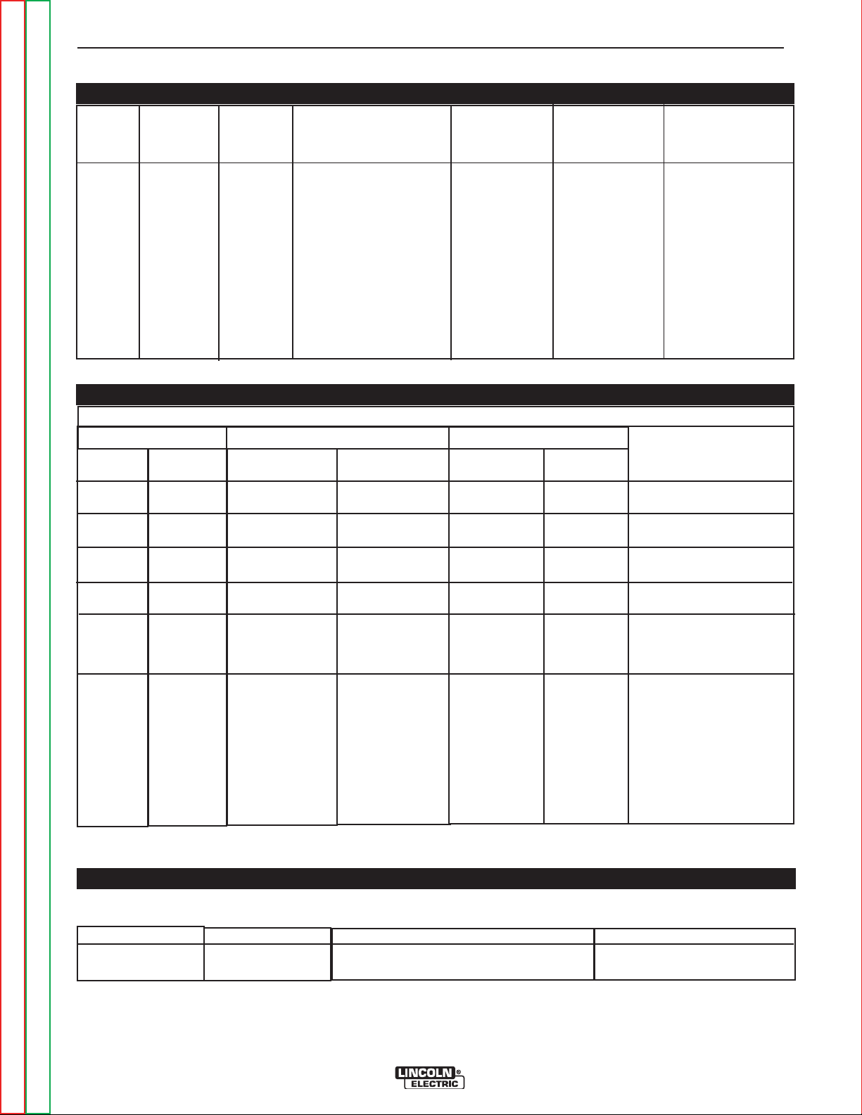
TECHNICAL SPECIFICATIONS -
POWER WAVE 355
INPUT AC VOLTAGE & DC OUTPUT
Product Ordering Input AC Rated DC Output Output Weight Dimensions
Name Information Voltage Amps/Volts/Duty Cycle Range with Cord HxWxD
(continuous)
Power
Wave
355
* Overall Length Including Handle, 21.6” (549mm) without handle.
K2152-1
200-208
220-240
380-415
440-480
575
60/50 HZ
350A / 34V / 60%
1 & 3 Phase
300A / 32V / 100%
1 & 3 Phase
AMPS
5-425
(81.5 lbs.)
(37.0 kg.)
14.8” x 13.3” x
27.8”*
(373 x 338 x
706*)mm
*Includes
Handles
POWER WAVE 355 INPUT CURRENT
Recommended Fuse Sizes Base On The U.S. National Electrical Code And Maximum Machine Outputs
Input 50/60 Hz Output Recommended
Voltage
200
208
230
380
400
415
460
575
Phases
1
1
1
1
1
1
1
1
300Amps @
32Volts(100%)
Not
Recommended
76
69
Not
Recommended
Not
Recommended
41
36
31
350Amps @
34Volts(60%)
Not
Recommended
94
85
Not
Recommended
Not
Recommended
64
42
37
Line Cord
AWG
2
4
---
6
8
8
Fuse size
---
125A
125A
---
---
80A
70A
50A
Notes
Note 1
Note 2
Note 2
Note 1
Note 1
Note 2
Return to Section TOC Return to Section TOC Return to Section TOC Return to Section TOC
200
208
230
380
400
415
460
575
Note 1. Not rated is indicated by 4-x’s in the box on the rating plate.
Note 2. When operating on these inputs, the line cord should be changed to an input conductor of 6 AWG or larger.
3
3
3
3
3
3
3
3
41
39
36
23
22
22
19
16
50
50
42
28
27
26
23
18
6
6
8
8
8
8
8
8
80A
80A
70A
50A
50A
50A
50A
35A
Note 2
Note 2
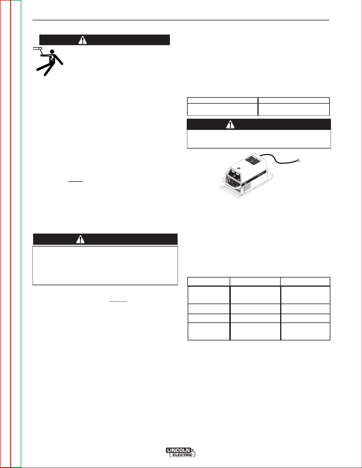
OUTPUT CABLES, CONNECTIONS AND LIMITATIONS
Select The output cable size based upon the following chart.*
Cable sizes for Combined Length of Electrode and Work Cable (Copper) 75C rated:
DUTY CYCLE
100%
60%
CURRENT
300
350
LENGTH UP 200FT.(61m)
1/0
1/0
200-250 FT. (61-76m)
1/0
2/0
*Lincoln Electric recommends using a minimum of 2/0 welding cable for pulse welding.
Return to Master TOC Return to Master TOC Return to Master TOC Return to Master TOC
POWER WAVE 355M/405M
Page 11
A-3 A-3
INSTALLATION
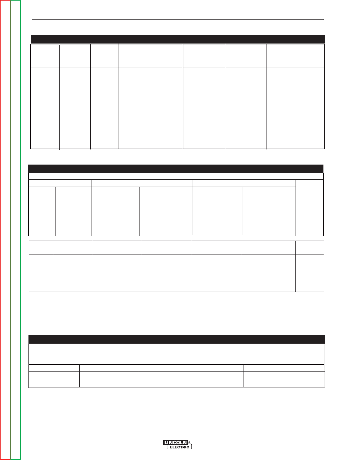
TECHNICAL SPECIFICATIONS -
POWER WAVE 405
INPUT AC VOLTAGE & DC OUTPUT
Product Ordering Input AC Rated DC Output Output Weight Dimensions
Name Information Voltage Amps/Volts/Duty Cycle Range with Cord HxWxD
(continuous)
335500AA // 3344VV // 6600%%
PPoowweerr 220000--220088 // 33 PPhhaassee 2277..88””**
WWaavvee KK 22115522--22 222200--224400// 332200AA // 3333VV // 6600%% AAMMPPSS 8866..55llbbss ((337733xx331188xx
440055 338800--441155// 11 PPhhaassee 55--442255 ((3377..44 kkgg)) 770066**))mmmm
33//5500//6600
6600//5500 HHzz227755AA // 3311VV //110000%%
11 PPhhaassee
330000AA // 3322VV // 110000%% ** IInncclluuddeess
33 PPhhaassee hhaannddlleess
* Overall Length Including Handle, 21.6” (549mm) without handle.
1144..77””xx1122..55””xx
POWER WAVE 405 INPUT CURRENT
Recommended Fuse Sizes Based On The U.S. National Electrical Code And Maximum Machine Outputs
Input 50/60 Hz Output Recommended
Voltage Phases 300Amps@ 350Amps@ Line Cord Size Fuse Size Notes
32Volts(100%) 34Volts(60%) Size mm
200 3 41 48 16 80A Note 2
220 3 37 48 16 80A Note 2
380 3 23 28 10 50A
400 3 22 27 10 50A
415 3 22 26 10 50A
2
Voltage Phases 275Amps@ 320Amps@ Line Cord Fuse Size Notes
31Volts(100%) 33Volts(60%) Size mm
200 1 Not Recommended Not Recommended --- ----- Note 1
220 1 64 82 20 125A Note 2
380 1 44 55 16 80A Note 2
400 1 40 50 10 80A
415 1 38 48 10 80A
1. Not rated is indicated by 4-x's in the box on the rating plate
2. When operating on these inputs, the line cord should be changed to an input conductor of 6 AWG or larger.
2
OUTPUT CABLES, CONNECTIONS AND LIMITATIONS
Select the output cable size based upon the following chart.
Cable sizes for Combined Length of Electrode and Work Cable (Copper) 75C rated:
DUTY CYCLE CURRENT LENGTH UP 61m (200 FT) 61-76m (200-250 FT)
100% 275 1/0 1/0
60% 350 1/0 2/0
Return to Section TOC Return to Section TOC Return to Section TOC Return to Section TOC
Return to Master TOC Return to Master TOC Return to Master TOC Return to Master TOC
POWER WAVE 355M/405M
Page 12
A-4 A-4
W
A
R
N
I
N
G
R
E
M
O
T
E
P
O
W
E
R
O
F
F
O
N
A
A
M
P
S
A
V
V
O
L
T
S
W
E
L
D
T
E
R
M
I
N
A
L
S
S
E
L
E
C
T
O
U
T
P
U
T
L
I
N
C
O
L
N
E
L
E
C
T
R
I
C
I
N
V
E
RTE
C
V
3
5
0
P
R
O
W
A
R
N
I
N
G
W
A
R
N
I
N
G
A
V
I
S
O
D
E
P
R
E
C
A
U
C
I
O
N
A
T
T
E
N
T
I
O
N
!
!
!
!
L
o
r
e
m
i
p
s
u
m
d
o
l
o
r
s
i
t
a
m
e
t
c
o
n
s
e
c
t
e
t
u
e
r
a
d
i
p
i
s
c
i
n
g
L
o
r
e
m
i
p
s
u
m
d
o
l
o
r
s
i
t
a
m
e
t
c
o
n
s
e
c
t
e
t
u
e
r
a
d
i
p
i
s
c
i
n
g
e
l
i
t
,
e
d
d
i
a
m
n
o
n
u
m
m
y
n
i
b
h
e
u
i
s
m
o
d
t
i
n
c
i
d
u
n
t
u
t
e
l
i
t
,
e
d
d
i
a
m
n
o
n
u
m
m
y
n
i
b
h
e
u
i
s
m
o
d
t
i
n
c
i
d
u
n
t
u
t
l
a
o
r
e
e
t
d
o
l
o
r
e
m
a
g
n
a
a
l
i
q
u
a
m
e
r
a
t
l
a
o
r
e
e
t
d
o
l
o
r
e
m
a
g
n
a
a
l
i
q
u
a
m
e
r
a
t
L
o
r
e
m
i
p
s
u
m
d
o
l
o
r
s
i
t
a
m
e
t
c
o
n
s
e
c
t
e
t
u
e
r
a
d
i
p
i
s
c
i
n
g
L
o
r
e
m
i
p
s
u
m
d
o
l
o
r
s
i
t
a
m
e
t
c
o
n
s
e
c
t
e
t
u
e
r
a
d
i
p
i
s
c
i
n
g
e
l
i
t
,
e
d
d
i
a
m
n
o
n
u
m
m
y
n
i
b
h
e
u
i
s
m
o
d
t
i
n
c
i
d
u
n
t
u
t
e
l
i
t
,
e
d
d
i
a
m
n
o
n
u
m
m
y
n
i
b
h
e
u
i
s
m
o
d
t
i
n
c
i
d
u
n
t
u
t
l
a
o
r
e
e
t
d
o
l
o
r
e
m
a
g
n
a
a
l
i
q
u
a
m
e
r
a
t
l
a
o
r
e
e
t
d
o
l
o
r
e
m
a
g
n
a
a
l
i
q
u
a
m
e
r
a
t
L
o
r
e
m
i
p
s
u
m
d
o
l
o
r
s
i
t
a
m
e
t
c
o
n
s
e
c
t
e
t
u
e
r
a
d
i
p
i
s
c
i
n
g
L
o
r
e
m
i
p
s
u
m
d
o
l
o
r
s
i
t
a
m
e
t
c
o
n
s
e
c
t
e
t
u
e
r
a
d
i
p
i
s
c
i
n
g
e
l
i
t
,
e
d
d
i
a
m
n
o
n
u
m
m
y
n
i
b
h
e
u
i
s
m
o
d
t
i
n
c
i
d
u
n
t
u
t
e
l
i
t
,
e
d
d
i
a
m
n
o
n
u
m
m
y
n
i
b
h
e
u
i
s
m
o
d
t
i
n
c
i
d
u
n
t
u
t
l
a
o
r
e
e
t
d
o
l
o
r
e
m
a
g
n
a
a
l
i
q
u
a
m
e
r
a
t
l
a
o
r
e
e
t
d
o
l
o
r
e
m
a
g
n
a
a
l
i
q
u
a
m
e
r
a
t
L
o
r
e
m
i
p
s
u
m
d
o
l
o
r
s
i
t
a
m
e
t
c
o
n
s
e
c
t
e
t
u
e
r
a
d
i
p
i
s
c
i
n
g
L
o
r
e
m
i
p
s
u
m
d
o
l
o
r
s
i
t
a
m
e
t
c
o
n
s
e
c
t
e
t
u
e
r
a
d
i
p
i
s
c
i
n
g
e
l
i
t
,
e
d
d
i
a
m
n
o
n
u
m
m
y
n
i
b
h
e
u
i
s
m
o
d
t
i
n
c
i
d
u
n
t
u
t
e
l
i
t
,
e
d
d
i
a
m
n
o
n
u
m
m
y
n
i
b
h
e
u
i
s
m
o
d
t
i
n
c
i
d
u
n
t
u
t
l
a
o
r
e
e
t
d
o
l
o
r
e
m
a
g
n
a
a
l
i
q
u
a
m
e
r
a
t
l
a
o
r
e
e
t
d
o
l
o
r
e
m
a
g
n
a
a
l
i
q
u
a
m
e
r
a
t
L
o
r
e
m
i
p
s
u
m
d
o
l
o
r
s
i
t
a
m
e
t
c
o
n
s
e
c
t
e
t
u
e
r
a
d
i
p
i
s
c
i
n
g
L
o
r
e
m
i
p
s
u
m
d
o
l
o
r
s
i
t
a
m
e
t
c
o
n
s
e
c
t
e
t
u
e
r
a
d
i
p
i
s
c
i
n
g
e
l
i
t
,
e
d
d
i
a
m
n
o
n
u
m
m
y
n
i
b
h
e
u
i
s
m
o
d
t
i
n
c
i
d
u
n
t
u
t
e
l
i
t
,
e
d
d
i
a
m
n
o
n
u
m
m
y
n
i
b
h
e
u
i
s
m
o
d
t
i
n
c
i
d
u
n
t
u
t
l
a
o
r
e
e
t
d
o
l
o
r
e
m
a
g
n
a
a
l
i
q
u
a
m
e
r
a
t
l
a
o
r
e
e
t
d
o
l
o
r
e
m
a
g
n
a
a
l
i
q
u
a
m
e
r
a
t
L
o
r
e
m
i
p
s
u
m
d
o
l
o
r
s
i
t
a
m
e
t
c
o
n
s
e
c
t
e
t
u
e
r
a
d
i
p
i
s
c
i
n
g
L
o
r
e
m
i
p
s
u
m
d
o
l
o
r
s
i
t
a
m
e
t
c
o
n
s
e
c
t
e
t
u
e
r
a
d
i
p
i
s
c
i
n
g
e
l
i
t
,
e
d
d
i
a
m
n
o
n
u
m
m
y
n
i
b
h
e
u
i
s
m
o
d
t
i
n
c
i
d
u
n
t
u
t
e
l
i
t
,
e
d
d
i
a
m
n
o
n
u
m
m
y
n
i
b
h
e
u
i
s
m
o
d
t
i
n
c
i
d
u
n
t
u
t
l
a
o
r
e
e
t
d
o
l
o
r
e
m
a
g
n
a
a
l
i
q
u
a
m
e
r
a
t
l
a
o
r
e
e
t
d
o
l
o
r
e
m
a
g
n
a
a
l
i
q
u
a
m
e
r
a
t
L
o
r
e
m
i
p
s
u
m
d
o
l
o
r
s
i
t
a
m
e
t
c
o
n
s
e
c
t
e
t
u
e
r
a
d
i
p
i
s
c
i
n
g
L
o
r
e
m
i
p
s
u
m
d
o
l
o
r
s
i
t
a
m
e
t
c
o
n
s
e
c
t
e
t
u
e
r
a
d
i
p
i
s
c
i
n
g
e
l
i
t
,
e
d
d
i
a
m
n
o
n
u
m
m
y
n
i
b
h
e
u
i
s
m
o
d
t
i
n
c
i
d
u
n
t
u
t
e
l
i
t
,
e
d
d
i
a
m
n
o
n
u
m
m
y
n
i
b
h
e
u
i
s
m
o
d
t
i
n
c
i
d
u
n
t
u
t
l
a
o
r
e
e
t
d
o
l
o
r
e
m
a
g
n
a
a
l
i
q
u
a
m
e
r
a
t
l
a
o
r
e
e
t
d
o
l
o
r
e
m
a
g
n
a
a
l
i
q
u
a
m
e
r
a
t
L
o
r
e
m
i
p
s
u
m
d
o
l
o
r
s
i
t
a
m
e
t
c
o
n
s
e
c
t
e
t
u
e
r
a
d
i
p
i
s
c
i
n
g
L
o
r
e
m
i
p
s
u
m
d
o
l
o
r
s
i
t
a
m
e
t
c
o
n
s
e
c
t
e
t
u
e
r
a
d
i
p
i
s
c
i
n
g
e
l
i
t
,
e
d
d
i
a
m
n
o
n
u
m
m
y
n
i
b
h
e
u
i
s
m
o
d
t
i
n
c
i
d
u
n
t
u
t
e
l
i
t
,
e
d
d
i
a
m
n
o
n
u
m
m
y
n
i
b
h
e
u
i
s
m
o
d
t
i
n
c
i
d
u
n
t
u
t
l
a
o
r
e
e
t
d
o
l
o
r
e
m
a
g
n
a
a
l
i
q
u
a
m
e
r
a
t
l
a
o
r
e
e
t
d
o
l
o
r
e
m
a
g
n
a
a
l
i
q
u
a
m
e
r
a
t
L
o
r
e
m
i
p
s
u
m
d
o
l
o
r
s
i
t
a
m
e
t
c
o
n
s
e
c
t
e
t
u
e
r
a
d
i
p
i
s
c
i
n
g
L
o
r
e
m
i
p
s
u
m
d
o
l
o
r
s
i
t
a
m
e
t
c
o
n
s
e
c
t
e
t
u
e
r
a
d
i
p
i
s
c
i
n
g
e
l
i
t
,
e
d
d
i
a
m
n
o
n
u
m
m
y
n
i
b
h
e
u
i
s
m
o
d
t
i
n
c
i
d
u
n
t
u
t
e
l
i
t
,
e
d
d
i
a
m
n
o
n
u
m
m
y
n
i
b
h
e
u
i
s
m
o
d
t
i
n
c
i
d
u
n
t
u
t
l
a
o
r
e
e
t
d
o
l
o
r
e
m
a
g
n
a
a
l
i
q
u
a
m
e
r
a
t
l
a
o
r
e
e
t
d
o
l
o
r
e
m
a
g
n
a
a
l
i
q
u
a
m
e
r
a
t
L
o
r
e
m
i
p
s
u
m
d
o
l
o
r
s
i
t
a
m
e
t
c
o
n
s
e
c
t
e
t
u
e
r
a
d
i
p
i
s
c
i
n
g
L
o
r
e
m
i
p
s
u
m
d
o
l
o
r
s
i
t
a
m
e
t
c
o
n
s
e
c
t
e
t
u
e
r
a
d
i
p
i
s
c
i
n
g
e
l
i
t
,
e
d
d
i
a
m
n
o
n
u
m
m
y
n
i
b
h
e
u
i
s
m
o
d
t
i
n
c
i
d
u
n
t
u
t
e
l
i
t
,
e
d
d
i
a
m
n
o
n
u
m
m
y
n
i
b
h
e
u
i
s
m
o
d
t
i
n
c
i
d
u
n
t
u
t
l
a
o
r
e
e
t
d
o
l
o
r
e
m
a
g
n
a
a
l
i
q
u
a
m
e
r
a
t
l
a
o
r
e
e
t
d
o
l
o
r
e
m
a
g
n
a
a
l
i
q
u
a
m
e
r
a
t
L
o
r
e
m
i
p
s
u
m
d
o
l
o
r
s
i
t
a
m
e
t
c
o
n
s
e
c
t
e
t
u
e
r
a
d
i
p
i
s
c
i
n
g
L
o
r
e
m
i
p
s
u
m
d
o
l
o
r
s
i
t
a
m
e
t
c
o
n
s
e
c
t
e
t
u
e
r
a
d
i
p
i
s
c
i
n
g
e
l
i
t
,
e
d
d
i
a
m
n
o
n
u
m
m
y
n
i
b
h
e
u
i
s
m
o
d
t
i
n
c
i
d
u
n
t
u
t
e
l
i
t
,
e
d
d
i
a
m
n
o
n
u
m
m
y
n
i
b
h
e
u
i
s
m
o
d
t
i
n
c
i
d
u
n
t
u
t
l
a
o
r
e
e
t
d
o
l
o
r
e
m
a
g
n
a
a
l
i
q
u
a
m
e
r
a
t
l
a
o
r
e
e
t
d
o
l
o
r
e
m
a
g
n
a
a
l
i
q
u
a
m
e
r
a
t
L
o
r
e
m
i
p
s
u
m
d
o
l
o
r
s
i
t
a
m
e
t
c
o
n
s
e
c
t
e
t
u
e
r
a
d
i
p
i
s
c
i
n
g
L
o
r
e
m
i
p
s
u
m
d
o
l
o
r
s
i
t
a
m
e
t
c
o
n
s
e
c
t
e
t
u
e
r
a
d
i
p
i
s
c
i
n
g
e
l
i
t
,
e
d
d
i
a
m
n
o
n
u
m
m
y
n
i
b
h
e
u
i
s
m
o
d
t
i
n
c
i
d
u
n
t
u
t
e
l
i
t
,
e
d
d
i
a
m
n
o
n
u
m
m
y
n
i
b
h
e
u
i
s
m
o
d
t
i
n
c
i
d
u
n
t
u
t
l
a
o
r
e
e
t
d
o
l
o
r
e
m
a
g
n
a
a
l
i
q
u
a
m
e
r
a
t
l
a
o
r
e
e
t
d
o
l
o
r
e
m
a
g
n
a
a
l
i
q
u
a
m
e
r
a
t
L
o
r
e
m
i
p
s
u
m
d
o
l
o
r
s
i
t
a
m
e
t
c
o
n
s
e
c
t
e
t
u
e
r
a
d
i
p
i
s
c
i
n
g
L
o
r
e
m
i
p
s
u
m
d
o
l
o
r
s
i
t
a
m
e
t
c
o
n
s
e
c
t
e
t
u
e
r
a
d
i
p
i
s
c
i
n
g
e
l
i
t
,
e
d
d
i
a
m
n
o
n
u
m
m
y
n
i
b
h
e
u
i
s
m
o
d
t
i
n
c
i
d
u
n
t
u
t
e
l
i
t
,
e
d
d
i
a
m
n
o
n
u
m
m
y
n
i
b
h
e
u
i
s
m
o
d
t
i
n
c
i
d
u
n
t
u
t
l
a
o
r
e
e
t
d
o
l
o
r
e
m
a
g
n
a
a
l
i
q
u
a
m
e
r
a
t
l
a
o
r
e
e
t
d
o
l
o
r
e
m
a
g
n
a
a
l
i
q
u
a
m
e
r
a
t
L
o
r
e
m
i
p
s
u
m
d
o
l
o
r
s
i
t
a
m
e
t
c
o
n
s
e
c
t
e
t
u
e
r
a
d
i
p
i
s
c
i
n
g
L
o
r
e
m
i
p
s
u
m
d
o
l
o
r
s
i
t
a
m
e
t
c
o
n
s
e
c
t
e
t
u
e
r
a
d
i
p
i
s
c
i
n
g
e
l
i
t
,
e
d
d
i
a
m
n
o
n
u
m
m
y
n
i
b
h
e
u
i
s
m
o
d
t
i
n
c
i
d
u
n
t
u
t
e
l
i
t
,
e
d
d
i
a
m
n
o
n
u
m
m
y
n
i
b
h
e
u
i
s
m
o
d
t
i
n
c
i
d
u
n
t
u
t
l
a
o
r
e
e
t
d
o
l
o
r
e
m
a
g
n
a
a
l
i
q
u
a
m
e
r
a
t
l
a
o
r
e
e
t
d
o
l
o
r
e
m
a
g
n
a
a
l
i
q
u
a
m
e
r
a
t
L
o
r
e
m
i
p
s
u
m
d
o
l
o
r
s
i
t
a
m
e
t
c
o
n
s
e
c
t
e
t
u
e
r
a
d
i
p
i
s
c
i
n
g
L
o
r
e
m
i
p
s
u
m
d
o
l
o
r
s
i
t
a
m
e
t
c
o
n
s
e
c
t
e
t
u
e
r
a
d
i
p
i
s
c
i
n
g
e
l
i
t
,
e
d
d
i
a
m
n
o
n
u
m
m
y
n
i
b
h
e
u
i
s
m
o
d
t
i
n
c
i
d
u
n
t
u
t
e
l
i
t
,
e
d
d
i
a
m
n
o
n
u
m
m
y
n
i
b
h
e
u
i
s
m
o
d
t
i
n
c
i
d
u
n
t
u
t
l
a
o
r
e
e
t
d
o
l
o
r
e
m
a
g
n
a
a
l
i
q
u
a
m
e
r
a
t
l
a
o
r
e
e
t
d
o
l
o
r
e
m
a
g
n
a
a
l
i
q
u
a
m
e
r
a
t
L
o
r
e
m
i
p
s
u
m
d
o
l
o
r
s
i
t
a
m
e
t
c
o
n
s
e
c
t
e
t
u
e
r
a
d
i
p
i
s
c
i
n
g
L
o
r
e
m
i
p
s
u
m
d
o
l
o
r
s
i
t
a
m
e
t
c
o
n
s
e
c
t
e
t
u
e
r
a
d
i
p
i
s
c
i
n
g
e
l
i
t
,
e
d
d
i
a
m
n
o
n
u
m
m
y
n
i
b
h
e
u
i
s
m
o
d
t
i
n
c
i
d
u
n
t
u
t
e
l
i
t
,
e
d
d
i
a
m
n
o
n
u
m
m
y
n
i
b
h
e
u
i
s
m
o
d
t
i
n
c
i
d
u
n
t
u
t
l
a
o
r
e
e
t
d
o
l
o
r
e
m
a
g
n
a
a
l
i
q
u
a
m
e
r
a
t
l
a
o
r
e
e
t
d
o
l
o
r
e
m
a
g
n
a
a
l
i
q
u
a
m
e
r
a
t
L
o
r
e
m
i
p
s
u
m
d
o
l
o
r
s
i
t
a
m
e
t
c
o
n
s
e
c
t
e
t
u
e
r
a
d
i
p
i
s
c
i
n
g
L
o
r
e
m
i
p
s
u
m
d
o
l
o
r
s
i
t
a
m
e
t
c
o
n
s
e
c
t
e
t
u
e
r
a
d
i
p
i
s
c
i
n
g
e
l
i
t
,
e
d
d
i
a
m
n
o
n
u
m
m
y
n
i
b
h
e
u
i
s
m
o
d
t
i
n
c
i
d
u
n
t
u
t
e
l
i
t
,
e
d
d
i
a
m
n
o
n
u
m
m
y
n
i
b
h
e
u
i
s
m
o
d
t
i
n
c
i
d
u
n
t
u
t
l
a
o
r
e
e
t
d
o
l
o
r
e
m
a
g
n
a
a
l
i
q
u
a
m
e
r
a
t
l
a
o
r
e
e
t
d
o
l
o
r
e
m
a
g
n
a
a
l
i
q
u
a
m
e
r
a
t
L
o
r
e
m
i
p
s
u
m
d
o
l
o
r
s
i
t
a
m
e
t
c
o
n
s
e
c
t
e
t
u
e
r
a
d
i
p
i
s
c
i
n
g
L
o
r
e
m
i
p
s
u
m
d
o
l
o
r
s
i
t
a
m
e
t
c
o
n
s
e
c
t
e
t
u
e
r
a
d
i
p
i
s
c
i
n
g
e
l
i
t
,
e
d
d
i
a
m
n
o
n
u
m
m
y
n
i
b
h
e
u
i
s
m
o
d
t
i
n
c
i
d
u
n
t
u
t
e
l
i
t
,
e
d
d
i
a
m
n
o
n
u
m
m
y
n
i
b
h
e
u
i
s
m
o
d
t
i
n
c
i
d
u
n
t
u
t
l
a
o
r
e
e
t
d
o
l
o
r
e
m
a
g
n
a
a
l
i
q
u
a
m
e
r
a
t
l
a
o
r
e
e
t
d
o
l
o
r
e
m
a
g
n
a
a
l
i
q
u
a
m
e
r
a
t
L
o
r
e
m
i
p
s
u
m
d
o
l
o
r
s
i
t
a
m
e
t
c
o
n
s
e
c
t
e
t
u
e
r
a
d
i
p
i
s
c
i
n
g
L
o
r
e
m
i
p
s
u
m
d
o
l
o
r
s
i
t
a
m
e
t
c
o
n
s
e
c
t
e
t
u
e
r
a
d
i
p
i
s
c
i
n
g
e
l
i
t
,
e
d
d
i
a
m
n
o
n
u
m
m
y
n
i
b
h
e
u
i
s
m
o
d
t
i
n
c
i
d
u
n
t
u
t
e
l
i
t
,
e
d
d
i
a
m
n
o
n
u
m
m
y
n
i
b
h
e
u
i
s
m
o
d
t
i
n
c
i
d
u
n
t
u
t
l
a
o
r
e
e
t
d
o
l
o
r
e
m
a
g
n
a
a
l
i
q
u
a
m
e
r
a
t
l
a
o
r
e
e
t
d
o
l
o
r
e
m
a
g
n
a
a
l
i
q
u
a
m
e
r
a
t
INSTALLATION
Return to Section TOC Return to Section TOC Return to Section TOC Return to Section TOC
SAFETY PRECAUTIONS
WARNING
ELECTRIC SHOCK can kill.
• TURN THE INPUT POWER OFF AT
THE DISCONNECT SWITCH BEFORE
ATTEMPTING TO CONNECT OR DIS-
CONNECT INPUT POWER LINES, OUTPUT
CABLES, OR CONTROL CABLES.
• Only qualified personnel should perform this
installation.
• Connect the green/yellow lead of the power cord
to ground per U.S.National Electrical Code.
----------------------------------------------------------------------
SELECT SUITABLE LOCATION
In order to assure long life and reliable operation,
the owner of this machine should follow these simple preventative measures:
• The machine must be located where there is free circulation of clean
back, out the sides and bottom will not be restricted.
• Dirt and dust that can be drawn into the machine
should be kept to a minimum. Failure to observe
these precautions can result in excessive operating
temperatures and nuisance shutdown.
• Keep machine dry. Shelter from rain and snow. Do not
place on wet ground or in puddles.
air such that air movement in the
CAUTION
• DO NOT MOUNT OVER COMBUSTIBLE SURFACES.
Where there is a combustible surface directly under
stationary or fixed electrical equipment, that surface
shall be covered with a steel plate at least .06”(1.6mm)
thick, which shall extend not less than 5.90”(150mm)
beyond the equipment on all sides.
STACKING
POWER WAVE 355M/405M cannot
TILTING
Place the machine directly on a secure, level surface or
on a recommended undercarriage. The machine may
topple over if this procedure is not followed.
INPUT AND GROUNDING CONNECTIONS
• Only a qualified electrician should connect the
POWER WAVE 355M/405M. Installation should be
made in accordance with the appropriate National
Electrical Code, all local codes and the information
detailed below.
• When received directly from the factory, multiple voltage machines are internally connected for the highest
voltage. Always double-check connections before
powering up the machine.
• Initial 200VAC - 415VAC and 575VAC operation will
Return to Master TOC Return to Master TOC Return to Master TOC Return to Master TOC
require an Input voltage panel setup.
be stacked.
• Open the access panel on the rear of the machine.
• For 200 or 230: Position the large switch to 200-
230.
For higher voltages: Position the large switch to
380-575.
• Move the "A" lead to the appropriate terminal.
POWER CORD CONNECTION
A power cord is provided and wired into the machine.
Follow the power cord connection instructions.
• Incorrect connection may result in equipment
damage.
Single Phase Input (PW 355M)
Connect green lead to ground per National Electrical
Code.
Connect black and white leads to power.
Wrap red lead with tape to provide 600V insulation.
Three Phase Input (PW 355M)
Connect green lead to ground per National Electric
Code.
Connect black, red and white leads to power.
Lead Color Single Phase Three Phase
Green
Black
White
Red
Single Phase Input (PW 405M)
Connect green/yellow lead to ground per National
Electrical Code.
Connect blue and brown leads to power.
Wrap black lead with tape to provide 600V insulation.
Three Phase Input (PW 405M)
Connect green/yellow lead to ground per National
Electric Code.
Connect black, blue and brown leads to power.
POWER WAVE 355M/405M
Machine
PW 355
PW 405
CAUTION
Connect to
ground per NEC
Power Lead
Power Lead
Tape, provide
600V insulation
Cord Length
10 Feet
5 Meters
Connect to
ground per NEC
Power Lead
Power Lead
Power Lead
Page 13
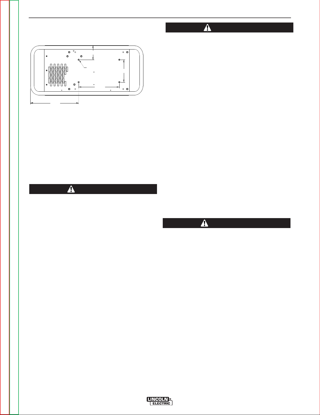
A-5 A-5
3
.44
21.60
2
7.82
5.50
10.00
M
OUNTING HOLE LOCATIONS
M19527
1/4-20 NUT (4 PLACES)
N
OTE: MOUNTING SCREWS CA
4/01
N NOT PROTR
UDE MORE THAN
0.5 IN
C
HES INSIDE THE MACHINE.
11.8
4
3.50
INSTALLATION
UNDERCARRIAGE MOUNTINGS
OUTPUT CABLES, CONNECTIONS AND
LIMITATIONS
Connect a work lead of sufficient size and length
between the proper output terminal on the power
source and the work. Be sure the connection to the
work makes tight metal-to-metal electrical contact. To
avoid interference problems with other equipment and
to achieve the best possible operation, route all cables
directly to the work or wire feeder. Avoid excessive
lengths and do not coil excess cable.
When using inverter type power sources like the
Power Waves, use the largest welding (electrode
and work) cables that are practical. At least 2/0
copper wire - even if the average output current
would not normally require it. When pulsing, the
pulse current can reach very high levels. Voltage
drops can become excessive, leading to poor welding characteristics, if undersized welding cables
are used.
-----------------------------------------------------------------------Most welding applications run with the electrode being
positive (+). For those applications, connect the electrode cable between the wire feeder and the positive
(+) output Twist-Mate terminal on the power source.
Connect the other end of the electrode cable to the
wire drive feed plate. The electrode cable lug must be
against the feed plate. Be sure the connection to the
feed plate makes tight metal-to-metal electrical contact. The electrode cable should be sized according to
the specifications given in the output cable connections
section. Connect a work lead from the negative (-)
power source output Twist-Mate terminal to the work
piece. The work piece connection must be firm and
secure, especially if pulse welding is planned.
CAUTION
CAUTION
Excessive voltage drops caused by poor work
piece connections often result in unsatisfactory
welding performance.
-----------------------------------------------------------------------
NEGATIVE ELECTRODE POLARITY
When negative electrode polarity is required, such as
in some Innershield applications, reverse the output
connections at the power source (electrode cable to
the negative (-) Twist-Mate terminal, and work cable
to the positive (+) Twist-Mate terminal.
When operating with electrode polarity negative the
"Electrode Sense Polarity" DIP switch must be set to
the "Negative" position on the Wire Drive Feed Head
PC Board. The default setting of the switch is positive
electrode polarity. Consult the Power Feed instruction
manual for further details.
VOLTAGE SENSING
The best arc performance occurs when the
PowerWaves have accurate data about the arc conditions. Depending upon the process, inductance within
the electrode and work lead cables can influence the
voltage apparent at the studs of the welder. Voltage
sense leads improve the accuracy of the arc conditions
and can have a dramatic effect on performance.
Sense Lead Kits (K940-10, -25 or -50) are available for
this purpose.
CAUTION
If the voltage sensing is enabled but the sense
leads are missing, improperly connected, or if the
electrode polarity switch is improperly configured,
extremely high welding outputs may occur.
-----------------------------------------------------------------------The ELECTRODE sense lead (67) is built into the control cable, and is automatically enabled for all semiautomatic processes. The WORK sense lead (21) connects to the Power Wave at the four pin connector. By
default the WORK voltage is monitored at the output
stud in the POWER WAVE 355/405. For more information on the WORK sense lead (21), see"Work Voltage
Sensing” in the following paragraph.
Return to Section TOC Return to Section TOC Return to Section TOC Return to Section TOC
For additional Safety information regarding the electrode and work cable set-up, See the standard "SAFETY INFORMATION" located in the front of the
Instruction Manuals.
Return to Master TOC Return to Master TOC Return to Master TOC Return to Master TOC
POWER WAVE 355M/405M
Page 14
A-6 A-6
INSTALLATION
Enable the voltage sense leads as follows:
TABLE A.1
Process Electrode Voltage Work Voltage
Sensing 67 lead * Sensing 21 lead
GMAW 67 lead required 21 lead optional
GMAW-P
FCAW 67 lead required 21 lead optional
GTAW
GMAW
SAW 67 lead required 21 lead optional
CAC-C
* The electrode voltage 67 sense lead is integral to the
control cable to the wire feeder.
Work Voltage Sensing
The standard POWER WAVE 355M/405M default to
the work stud (work sense lead disabled)
For processes requiring work voltage sensing, connect
the (21) work voltage sense lead (K940) from the
Power Wave work sense lead receptacle to the work
piece. Attach the sense lead to the work piece as close
to the weld as practical, but not in the return current
path. Enable the work voltage sensing in the Power
Wave as follows:
67 lead required 21 lead optional
Voltage sense at studs Voltage sense at studs
Voltage sense at studs Voltage sense at studs
Voltage sense at studs Voltage sense at studs
WARNING
• Do not touch electrically live parts or
electrodes with your skin or wet
clothing.
• Insulate yourself from the work and
ground.
• Always wear dry insulating gloves.
5. Replace the wrap around and screws. The PC board
will “read” the switch at power up, and configure the
work voltage sense lead appropriately.
ELECTRODE VOLTAGE SENSING
Enabling or disabling electrode voltage sensing is automatically configured through software. The 67 electrode sense lead is internal to the cable to the wire
feeder and always connected when a wire feeder is
present.
PF10M feeder has user preference features to select
voltage senses temporarily for testing sense leads.
CAUTION
Important: The electrode polarity must be configured at the feed head for all semi-automatic
processes. Failure to do so may result in extremely high welding outputs.
------------------------------------------------------------------------
POWER WAVE TO SEMI-AUTOMATIC POWERFEED WIRE FEEDER INTERCONNECTIONS
The POWER WAVE 355M/405M and semi-automatic
Power Feed family communicate via a 5 conductor
control cable (K1543). The control cable consists of two
power leads, one twisted pair for digital communication, and one lead for voltage sensing. The cables are
designed to be connected end to end for ease of extension. The output receptacle on the POWER WAVE
405M is on the case front. The input receptacle on the
Power Feed is typically located at the back of the feeder, or on the bottom of the user interface.
Return to Section TOC Return to Section TOC Return to Section TOC Return to Section TOC
1. Turn off power to the power source at the disconnect
switch.
2. Remove the wrap around cover from the power
source.
3. The control board is on the center assembly facing
the case front. Locate the 8-position DIP switch and
look for switch 8 of the DIP switch.
4. Using a pencil or other small object, slide the switch
to the OFF position if the work sense lead is NOT
connected. Conversely, slide the switch to the ON
position if the work sense lead is present.
O
N
12 3 456 7 8
Return to Master TOC Return to Master TOC Return to Master TOC Return to Master TOC
Due to the flexibility of the platform the configuration
may vary. The following is a general description of the
system. For specific configuration information, consult
the semi-automatic Power Feed instruction manual.
POWER WAVE 355M/405M
Page 15
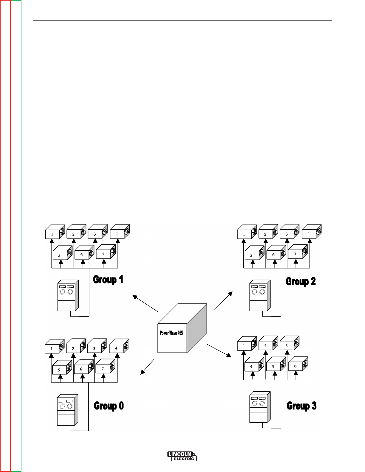
A-7 A-7
INSTALLATION
SYSTEM DESCRIPTION
The POWER WAVE 355M/405M and Power Feed
10/11 family of products utilize a digital communication
system called Arclink. Simply put, Arclink allows large
amounts of information to be passed at very high
speeds between components (nodes) in the system.
The system requires only two wires for communication,
and because of its bus-like structure, the components
may be connected to the network in any order, thus
simplifying the system set-up.
Each "system" must contain only one power source.
The power source may be connected to a maximum of
four feeder groups. Each group containing one user
interface (UI), and up to seven Feed Heads (FH). SEE
FIGURE A.1. The UI controls all of the FH’s of that
group. The UI’s and FH’s are assigned to groups by
setting a code on the DIP switches mounted on their
individual control boards. For example all of the FH’s to
be controlled by a given UI must have their "Group ID"
switches set to the same group number as the UI. In
addition, each FH must be assigned a separate FH
number within that group. See the system set-up section for further details.
From a network perspective, each component in the
system is considered a separate node, regardless of its
physical location. For example, even though a UI and
FH may be physically mounted together, they are still
viewed as separate pieces (nodes) by the network, and
can only communicate via Arclink. The connection is
generally made externally through the Linc-Net Control
Cable, but can also be made internally, as with the PF10 bench model feeder.
The most common Arclink configuration (called a simple system) consists of one power source, one user
interface and one feeder. Under these circumstances
the group and feed head ID DIP switches are ignored
and the system will function regardless of their position. The same is true for the minimum system consisting of a power source and one UI (Example: a stick
welding system).
System Model
FIGURE A.1
Maximum
Configuration
Return to Section TOC Return to Section TOC Return to Section TOC Return to Section TOC
Return to Master TOC Return to Master TOC Return to Master TOC Return to Master TOC
POWER WAVE 355M/405M
Page 16
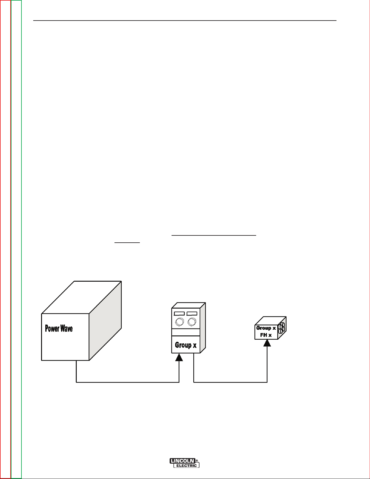
A-8 A-8
INSTALLATION
SYSTEM SET-UP
Basic Rules
• Each group is required to have one user interface. No
group may have more than one user interface.
• Each group can have up to seven Feed Heads.
Exception: Group 3 is limited to a maximum of six
Feed Heads.
• Each system has only one power source. For network
purposes, the PS belongs to Group 3, which is why
group 3 is only allowed 6 feed heads in addition to it’s
user interface.
• No two feed heads can have identical Group and
Feed Head numbers.
• Group and Feed Head ID numbers must be set on the
appropriate dip switches at each node. Consult the
PF-10/11 Instruction Manual for specific details
regarding dip switch settings.
Simple System
• Feed head “0” not allowed. Exception: Simple system ignores all ID numbers, therefore “FH0” will function.
• Each node must be connected to the Linc-Net communication network. The order of connection is not
important, as each node is identified by it’s unique
Group and Feed Head ID number as defined on it’s
dip switches. See Figures A.2 thru A.5.
FIGURE A.2
Group and Feed
Head ID numbers are
ignored in a simple
system.
Return to Section TOC Return to Section TOC Return to Section TOC Return to Section TOC
Return to Master TOC Return to Master TOC Return to Master TOC Return to Master TOC
POWER WAVE 355M/405M
Page 17
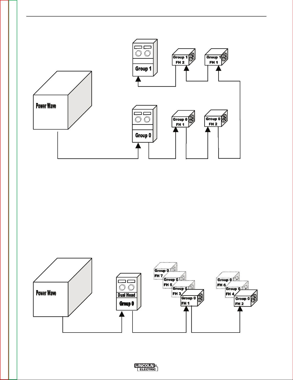
A-9 A-9
Multiple Group System
INSTALLATION
FIGURE A.3
No “FH0 Allowed!
Single Group Multi-Head System
FIGURE A.4
No “FH0 Allowed!
The Dual Head option
allows the ability to
maintain 2 sets of
procedures. If more
then 2 heads are
used, odd #’s use
FH1 settings, even #’s
use FH2 settings.
Return to Section TOC Return to Section TOC Return to Section TOC Return to Section TOC
Return to Master TOC Return to Master TOC Return to Master TOC Return to Master TOC
POWER WAVE 355M/405M
Page 18
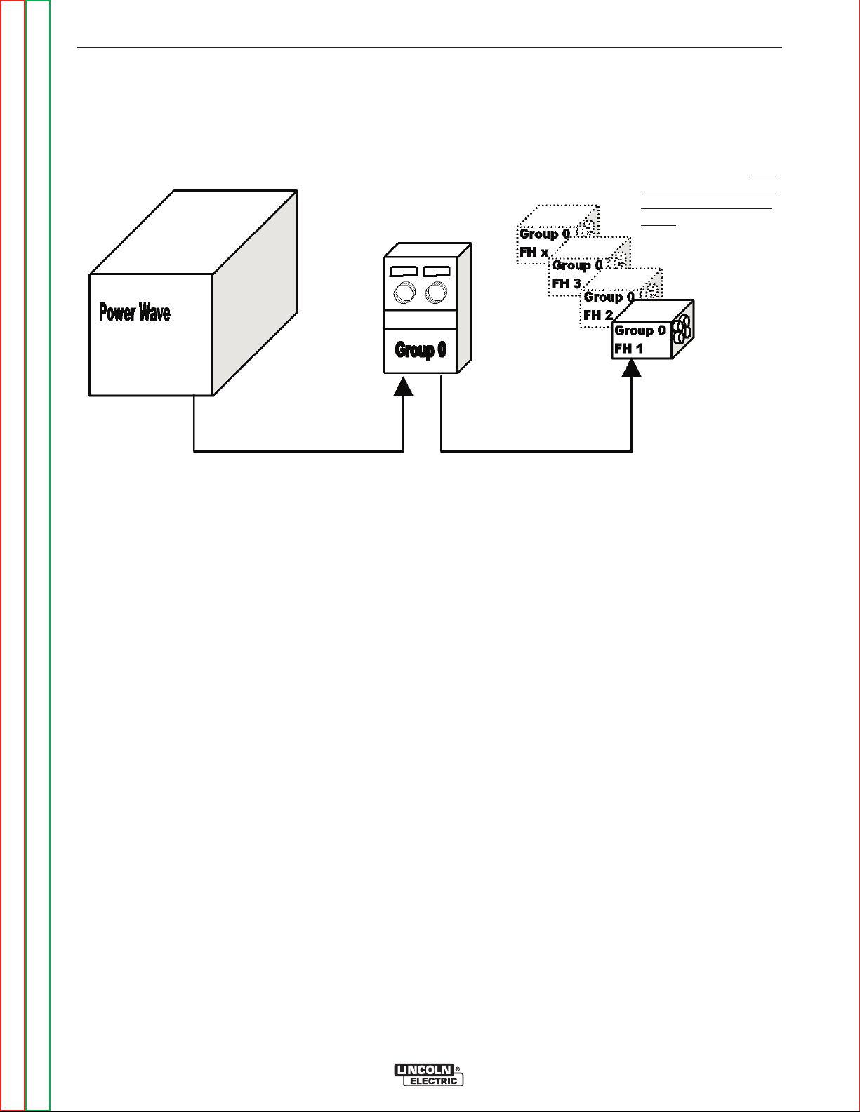
A-10 A-10
Single Group Multi-Head System (Alternate Method)
INSTALLATION
FIGURE A.5
No “FH0 Allowed!
When a standard
User Interface is used
in a group with multiple Feed Heads, all of
the Feed Heads use a
single set of proce-
.
dures
Return to Section TOC Return to Section TOC Return to Section TOC Return to Section TOC
Return to Master TOC Return to Master TOC Return to Master TOC Return to Master TOC
POWER WAVE 355M/405M
Page 19
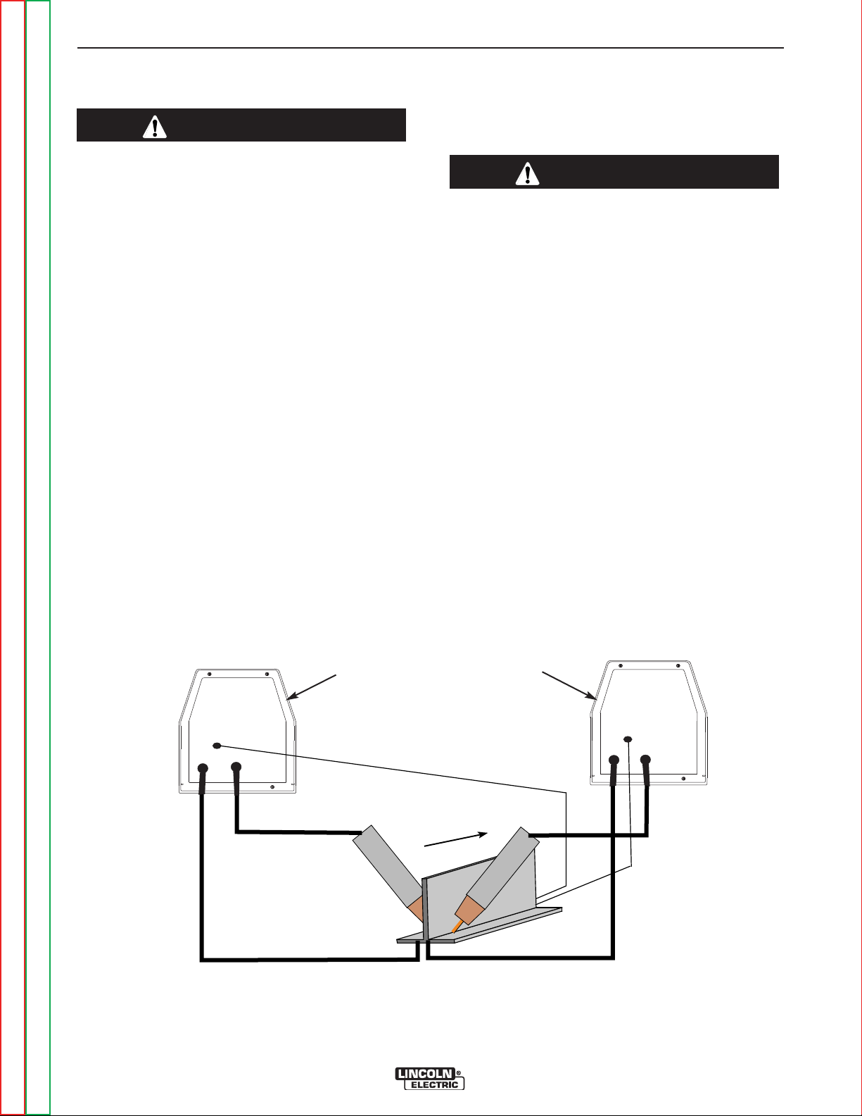
A-11 A-11
Connect All Work
Sense Leads at the End
of the Joint
Connect All Welding
Work Leads at the
Beginning of the Joint
Travel
Direction
P
OWER W
P
OWER WAAVVE 355/405E 355/405
POWER WPOWER WAAVVE 355/405E 355/405
INSTALLATION
WELDING WITH MULTIPLE POWER
WAVES
CAUTION
Special care must be taken when more than one
Power Wave is welding simultaneously on a single
part. Arc blow and arc interference may occur or be
magnified.
Each power source requires a work lead from the work
stud to the welding fixture. Do not combine all of the
work leads into one lead. The welding travel directions
should be in the direction moving away from the work
lead as shown below. Connect all of the work sense
leads from each power source to the work piece at the
end of the weld.
For the best results when pulse welding, set the wire
size and wire feed speed the same for all the Power
Waves. When these parameters are identical, the pulsing frequency will be the same, helping to stabilize the
arcs.
CONTROL CABLE SPECIFICATIONS
It is recommended that genuine Lincoln control cables
be used at all times. Lincoln cables are specifically
designed for the communication and power needs of
the Power Wave / Power Feed system.
CAUTION
The use of non-standard cables, especially in
lengths greater than 25 feet, can lead to communication problems such as: system shutdowns, poor
motor acceleration, poor arc starting) and low wire
driving force (wire feeding problems).
-----------------------------------------------------------------------The K1543 series of control cables can be connected
end to end for ease of extension. Do not exceed more
than 100 feet (30.5 m) total control cable length.
Every welding gun requires a separate shielding gas
regulator for proper flow rate and shielding gas coverage.
Do not attempt to supply shielding gas for two or more
guns from only one regulator.
If an anti-spatter system is in use then each gun must
have its own anti-spatter system. (See Figure A.6)
FIGURE A.6
TWO POWER WAVES
Return to Section TOC Return to Section TOC Return to Section TOC Return to Section TOC
Return to Master TOC Return to Master TOC Return to Master TOC Return to Master TOC
POWER WAVE 355M/405M
Page 20
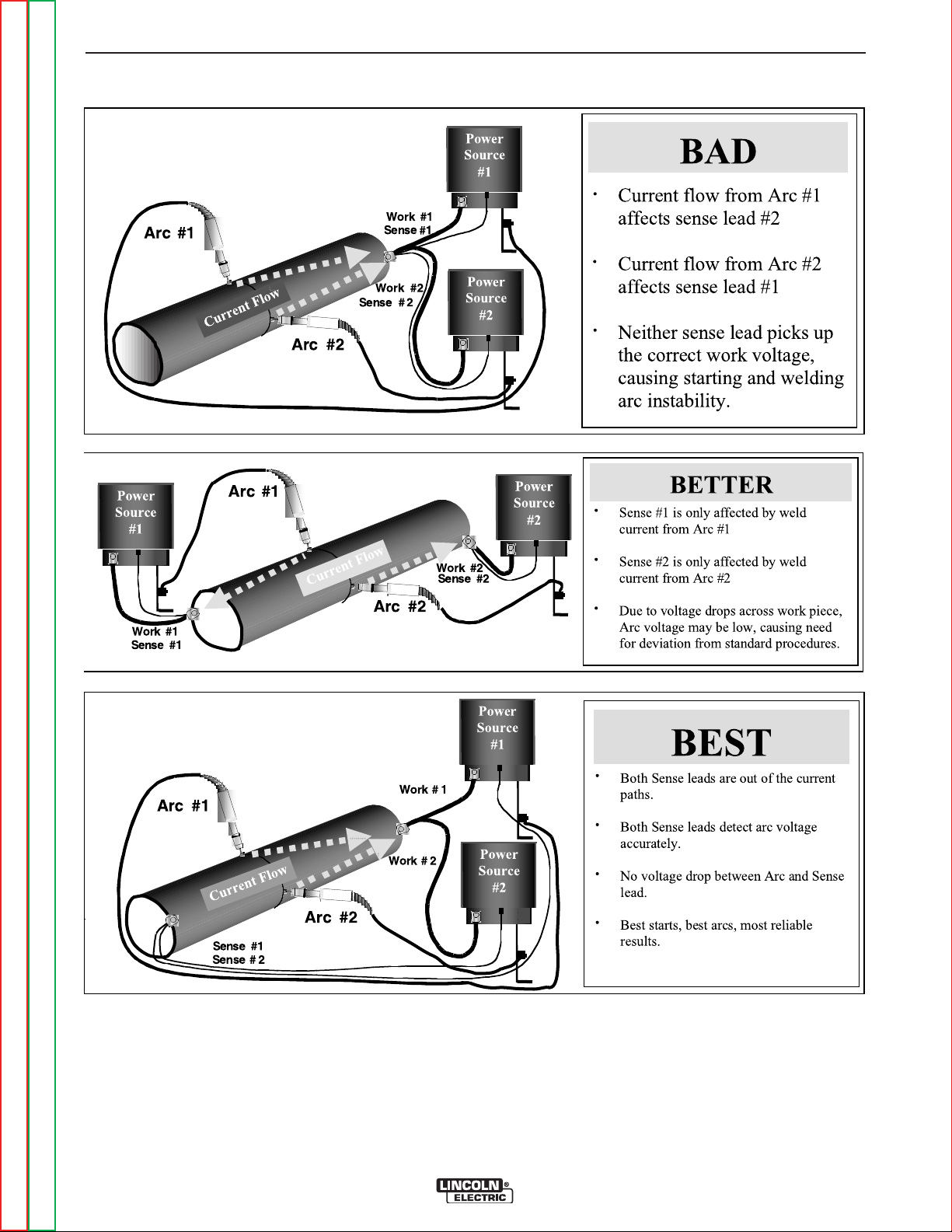
A-12 A-12
INSTALLATION
MULTIPLE ARC UNSYNCHRONIZED SENSE LEAD AND WORK LEAD PLACEMENT GUIDELINES
Return to Section TOC Return to Section TOC Return to Section TOC Return to Section TOC
Return to Master TOC Return to Master TOC Return to Master TOC Return to Master TOC
POWER WAVE 355M/405M
Page 21
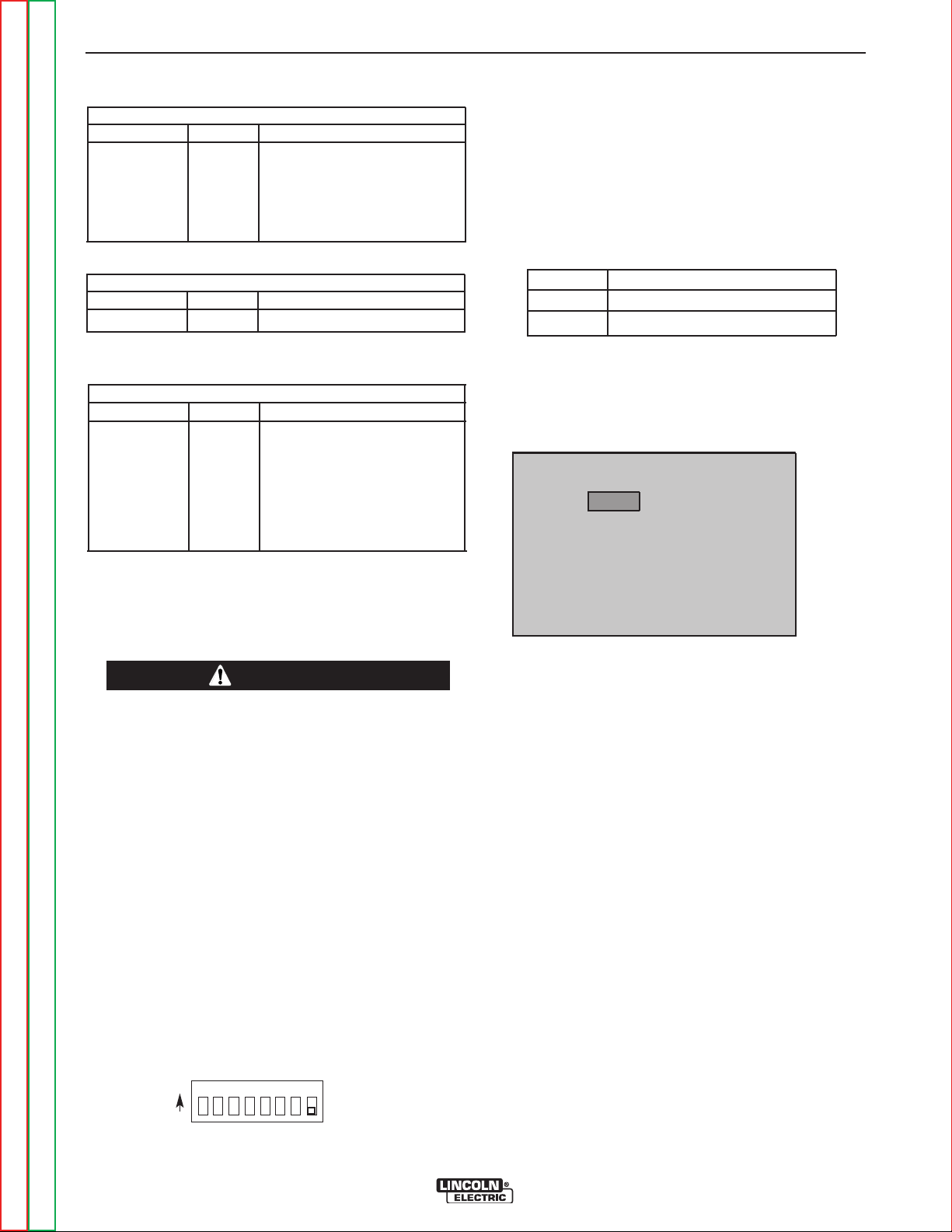
A-13 A-13
CONTROL BOARD (DIP Switch Location)
INSTALLATION
I / O RECEPTACLE SPECIFICATIONS
TABLE A.2
WIRE FEEDER RECEPTACLE
PIN LEAD# FUNCTION
A 53 Communication Bus L
B 54 Communication Bus H
C 67A Electrode Voltage Sense
D 52 +40vdc
E 51 0vdc
TABLE A.3
VOLTAGE SENSE RECEPTACLE
PIN LEAD# FUNCTION
3 21A Work Voltage Sense
TABLE A.4
RS232 RECEPTACLE
PIN LEAD# FUNCTION
2 253 RS232 Receive
3 254 RS232 Transmit
4#Pin5
5#Pin4
6 # # Pin20
20 # # Pin6
7 251 RS232 Common
CONTROL BOARD DIP SWITCH:
switch 1 = reserved for future use
switch 2 = reserved for future use
switch 3 = reserved for future use
switch 4 = reserved for future use
switch 5 = reserved for future use
switch 6 = reserved for future use
switch 7 = reserved for future use
switch 8* = work sense lead
switch 8*
off work sense lead not connected
on work sense lead connected
*Factory setting for Switch 8 is OFF.
work sense lead
FIGURE A.7
DIP SWITCH SETTINGS AND
LOCATIONS
DIP switches on the P.C. Boards allow for custom configuration of the Power Wave. To access the DIP switches:
WARNING
1. Turn off power to the power source at the disconnect switch.
------------------------------------------------------------------------
2. Remove the wrap around cover from the power
source.
3. The control board is on the center assembly facing
the case front. Locate the 8-position DIP switch and
look for switch 8 of the DIP switch.
4. Using a pencil or other small object, slide the switch
to the OFF position if the work sense lead is NOT
connected. Conversely, slide the switch to the ON
position if the work sense lead is present.
5. Replace the wrap around and screws. The PC board
will “read” the switch at power up, and configure the
work voltage sense lead appropriately.
NOTE: For PF10M Dual Boom Feeder set/up and op -
eration. The Power Wave 355M/405M control
board dip switches must be set with 3, 4, 7 to
the “ON” position (Power Wave 355M/405M
input on/off switch must be cycled to enable
any change of dip switches).
Return to Section TOC Return to Section TOC Return to Section TOC Return to Section TOC
Return to Master TOC Return to Master TOC Return to Master TOC Return to Master TOC
O
N
12 3 456 7 8
POWER WAVE 355M/405M
Page 22
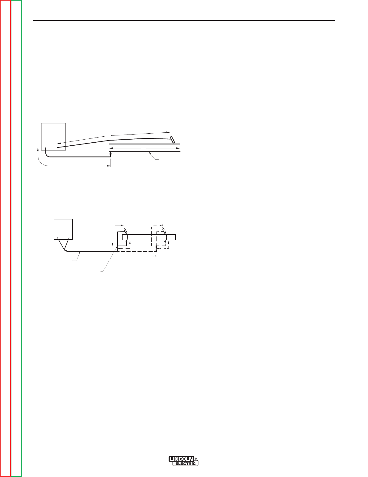
A-14 A-14
B
A
C
FIGURE A.3
POWER
WAVE
WORK
A
C
B
POWER
WAVE
FIGURE A.4
K1796 COAXIAL CABLE
MEASURE FROM END
OF OUTER JACKET OF
CABLE
C
A
B
WORK
SLIDING
WORK
INSTALLATION
CABLE INDUCTANCE, AND ITS EFFECTS
ON PULSE WELDING
For Pulse Welding processes, cable inductance will
cause the welding performance to degrade. For the
total welding loop length less than
tional welding cables may be used without any effects
on welding performance. For the total welding loop
length greater than
50 ft.(15.24m)), the K1796 Coaxial
Welding Cables are recommended. The welding loop
length is defined as the total of electrode cable length
(A) + work cable length (B) + work length (C) (See
Figure A.3).
For long work piece lengths, a sliding ground should be
considered to keep the total welding loop length less
50 ft.(15.24m). (See Figure A.4.)
than
50 ft.(15.24m), tradi-
Most welding applications run with the electrode being
positive (+). For those applications, connect the electrode cable between the wire feeder and the positive
(+) output Twist-Mate terminal on the power source.
Connect the other end of the electrode cable to the
wire drive feed plate. The electrode cable lug must be
against the feed plate. Be sure the connection to the
feed plate makes tight metal-to-metal electrical contact. The electrode cable should be sized according to
the specifications given in the output cable connections section. Connect a work lead from the negative
(-) power source output Twist-Mate terminal to the
work piece. The work piece connection must be firm
and secure, especially if pulse welding is planned.
For additional Safety information regarding the electrode and work cable set-up, See the standard "SAFETY INFORMATION" located in the front of the
Instruction Manuals.
Return to Master TOC Return to Master TOC Return to Master TOC Return to Master TOC
Return to Section TOC Return to Section TOC Return to Section TOC Return to Section TOC
POWER WAVE 355M/405M
Page 23

B-1 B-1
Operation . . . . . . . . . . . . . . . . . . . . . . . . . . . . . . . . . . . . . . . . . . . . . . . . . . . . . . . . . . . . . . . . . . . . . . . . . . . . . .B-1
Safety Precautions.......................................................................................................................................B-2
General Description .....................................................................................................................................B-2
Recommended Processes and Equipment .................................................................................................B-2
Required Equipment ....................................................................................................................................B-3
Limitations....................................................................................................................................................B-3
Duty Cycle and Time Period ........................................................................................................................B-3
Case Front Controls.....................................................................................................................................B-3
Making a Weld .............................................................................................................................................B-4
TABLE OF CONTENTS - OPERATION SECTION
Welding Adjustments ...................................................................................................................................B-4
Constant Voltage Welding............................................................................................................................B-5
Tig (GTAW) ...................................................................................................................................................B-6
Special Welding Processes Available ..........................................................................................................B-6
Power Mode.................................................................................................................................................B-7
Pulse Welding (GMAW-P) ............................................................................................................................B-8
Pulse-on-Pulse (GMAW-PP) ......................................................................................................................B-10
Benefits of Pulse-on-Pulse Welding ..........................................................................................................B-10
Return to Master TOC Return to Master TOC Return to Master TOC Return to Master TOC
POWER WAVE 355M/405M
Page 24
B-2 B-2
OPERATION
SAFETY PRECAUTIONS
Read this entire section of operating instructions
before operating the machine.
WARNING
ELECTRIC SHOCK can kill.
• Unless using cold feed feature, when
feeding with gun trigger, the electrode and drive mechanism are
always electrically energized and
could remain energized several sec-
onds after the welding ceases.
• Do not touch electrically live parts or electrodes
with your skin or wet clothing.
• Insulate yourself from the work and ground.
• Always wear dry insulating gloves.
-----------------------------------------------------------
FUMES AND GASES can be
dangerous.
GENERAL DESCRIPTION
The Power Wave semi-automatic power source is
designed to be a part of a modular, multi-process welding system. Depending on configuration, it can support
constant current, constant voltage, and pulse welding
modes.
The Power Wave power source is designed to be used
with the semi automatic family of Power Feed M wire
feeders, operating as a system. Each component in the
system has special circuitry to "talk with" the other system components, so each component (power source,
wire feeder, user interface) knows what the other is
doing at all times. These components communicate
with Arclink.
The POWER WAVE 355M/405M is a high performance, digitally controlled inverter welding power
source capable of complex, high-speed waveform control. Properly equipped, it can support the GMAW,
GMAW-P, FCAW, SMAW, GTAW, and CAC-A processes. It carries an output rating of 350 Amps, 34 Volts at
60% duty cycle and 300 Amps, 32 volts at 100% duty
cycle.
• Keep your head out of fumes.
• Use ventilation or exhaust to remove fumes from
breathing zone.
-----------------------------------------------------------
WELDING SPARKS can cause
fire or explosion.
• Keep flammable material away.
• Do not weld on containers that have
held combustibles.
-----------------------------------------------------------
ARC RAYS can burn.
• Wear eye, ear, and body protection.
-----------------------------------------------------------
Observe additional guidelines detailed in the
beginning of this manual.
RECOMMENDED PROCESSES
AND EQUIPMENT
RECOMMENDED PROCESSES
The POWER WAVE 355M/405M can be set up in a
number of configurations, some requiring optional
equipment or welding programs. Each machine is factory preprogrammed with multiple welding procedures,
typically including GMAW, GMAW-P, FCAW, GTAW,
and CAC-A for a variety of materials, including mild
steel, stainless steel, cored wires, and aluminum.
The POWER WAVE 355M/405M is recommended for
semi-automatic welding, and may also be suitable for
basic hard automation applications.
• This Power Wave is not recommended for processes
other than those listed.
Return to Section TOC Return to Section TOC Return to Section TOC Return to Section TOC
Return to Master TOC Return to Master TOC Return to Master TOC Return to Master TOC
POWER WAVE 355M/405M
Page 25

B-3 B-3
OPERATION
POWER WAVE 355M/405M – Semi-Automatic
Operation
Semi Automatic Power Waves can only be used with
Arclink compatible Power Feed semi-automatic wire
feeders. In addition, the Power Feed semi-automatic
wire feeders may require optional equipment to access
certain weld modes in the Power Wave. Other models
of Lincoln feeders, or any models of non-Lincoln wire
feeders, cannot be used.
All welding programs and procedures are selected
through the Power Feed semi-automatic user interface
REQUIRED EQUIPMENT
Any Arclink compatible semi-automatic wire feeding
equipment. Specifically, the semi-automatic Power
Feed family (PF10M Series, Power Feed 15M and
Power Feed 25M).
LIMITATIONS
• Only Arclink compatible Power Feed semi-automatic
wire feeders and users interfaces may be used.
Other Lincoln wire feeders or non-Lincoln wire feeders cannot be used.
• POWER WAVE 355M/405M Output Limitations
The POWER WAVE 355M/405M will support maximum average output current of 350 Amps @ 60%
duty cycle.
NOTE: The POWER WAVE 355M/405M status light
will flash green, and sometimes red and green, for up
to one minute when the machine is first turned on. This
is a normal situation as the machine goes through a
self test at power up.
TABLE B.1
Light
Condition
Steady Green
Blinking
Green
Alternating
Green and
Red
System OK. Power source communicating
normally with wire feeder and its components
if other feeder & components show they are
powered up.
Occurs during a reset, and indicates the
POWER WAVE 355M/405M is mapping
(identifying) each component in the system.
Normal for first 1-10 seconds after power is
turned on, or if the system configuration is
changed during operation
Non-recoverable system fault. If the PW
Status light is flashing any combination of red
and green, errors are present in the POWER
WAVE 355M/405M. Read the error code
before the machine is turned off.
Error Code interpretation through the Status
light is detailed in the LED Status Chart.
Individual code digits are flashed in red with
a long pause between digits. If more than
one code is present, the codes will be separated by a green light.
Meaning
DUTY CYCLE AND TIME PERIOD
The duty cycle is based upon a ten minute period. A
60% duty cycle represents 6 minutes of welding and 4
minutes of idling in a ten minute period.
CASE FRONT CONTROLS
All operator controls and adjustments are located on
the case front of the Power Wave. (See Figure B.1)
1. POWER SWITCH: Controls input power to the
Power Wave.
2. STATUS LIGHT: A two color light that indicates sys-
tem errors. Normal operation is a steady green light.
Error conditions are indicated, per table B.1.
To clear the error, turn power source off, and
back on to reset.
Steady Red
Blinking Red
Non recoverable hardware fault. Generally
indicates nothing is connected to the
POWER WAVE 355M/405M wire feeder
receptacle. See Trouble Shooting Section.
Not applicable.
3. HIGH TEMPERATURE LIGHT (thermal overload):
A yellow light that comes on when an over temperature situation occurs. Output is disabled and the
fan continues to run, until the machine cools down.
When cool, the light goes out and output is enabled.
4. CB1 WIRE FEEDER CIRCUIT BREAKER: Protects
40 volt DC wire feeder power supply.
Return to Section TOC Return to Section TOC Return to Section TOC Return to Section TOC
Return to Master TOC Return to Master TOC Return to Master TOC Return to Master TOC
POWER WAVE 355M/405M
Page 26
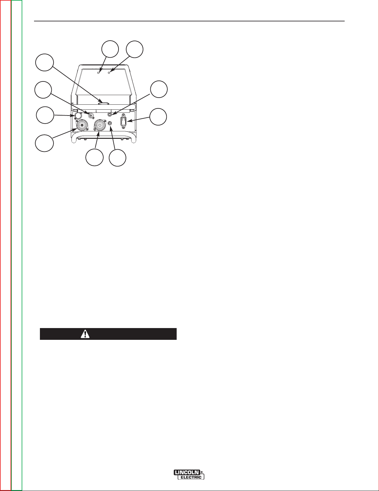
B-4 B-4
OPERATION
FIGURE B.1
2
3
7
6
8
4
1
9
10
5
CASE FRONT LAYOUT
POWER WAVE 355M/405M
5.
Internal POWER CIRCUIT BREAKER:
volt AC circuit.
6. LEAD CONNECTOR (SENSE LEAD)
7. DIAGNOSTIC CONNECTOR (RS-232)
8. WIRE FEEDER RECEPTACLE (5-PIN)
9. NEGATIVE TWIST- MATE TERMINAL
10. POSITIVE TWIST- MATE TERMINAL
Protects 115
NOMINAL PROCEDURES
The Power Wave is designed to operate with 3/4" electrode stick-out for CV and Pulse processes.
FRINGE PROCEDURES
Excessively short or long electrode stick-outs may
function only on a limited basis, if at all.
MAKING A WELD
WARNING
The serviceability of a product or structure utilizing the welding programs is and must be the sole
responsibility of the builder/user. Many variables
beyond the control of The Lincoln Electric
Company affect the results obtained in applying
these programs. These variables include, but are
not limited to, welding procedure, plate chemistry
and temperature, weldment design, fabrication
methods and service requirements. The available
range of a welding program may not be suitable for
all applications, and the build/user is and must be
solely responsible for welding program selection.
------------------------------------------------------------------------
The steps for operating the Power Wave will vary
depending upon the options installed in the user interface (control box) of the welding system. The flexibility
of the Power Wave system lets the user customize
operation for the best performance.
First, consider the desired welding process and the
part to be welded. Choose an electrode material, diameter, shielding gas and process (GMAW, GMAW-P,
etc.)
Second, find the program in the welding software that
best matches the desired welding process. The standard software shipped with the Power Waves encompasses a wide range of common processes and will
meet most needs. If a special welding program is
desired, contact the local Lincoln Electric sales representative.
To make a weld, the Power Wave needs to know the
desired welding parameters. The Power Feed (PF)
family of feeders communicate settings to the Power
Wave through control cable connection. Arc length,
wire feed speed, arc control, etc. are all communicated
digitally via the control cable.
WELDING ADJUSTMENTS
All adjustments are made on the system component
known as the User Interface (Control Box), which contains the switches, knobs, and digital displays necessary to control both the Power Wave and a Power Feed
wire feeder. Typically, the Control Box is supplied as
part of the wire feeder. It can be mounted directly on
the wire feeder itself, the front of the power source, or
mounted separately, as might be done in a welding
boom installation.
Because the Control Box can be configured with many
different options, your system may not have all of the
following adjustments. Regardless of availability, all
controls are described below. For further information,
consult the Power Feed wire feeder instruction manual.
• WFS / AMPS:
In synergic welding modes (synergic CV, pulse GMAW)
WFS (wire feed speed) is the dominant control parameter, controlling all other variables. The user adjusts
WFS according to factors such as weld size, penetration requirements, heat input, etc. The Power Wave
then uses the WFS setting to adjust its output characteristics (output voltage, output current) according to
pre-programmed settings contained in the Power
Wave.
Return to Section TOC Return to Section TOC Return to Section TOC Return to Section TOC
Return to Master TOC Return to Master TOC Return to Master TOC Return to Master TOC
POWER WAVE 355M/405M
Page 27
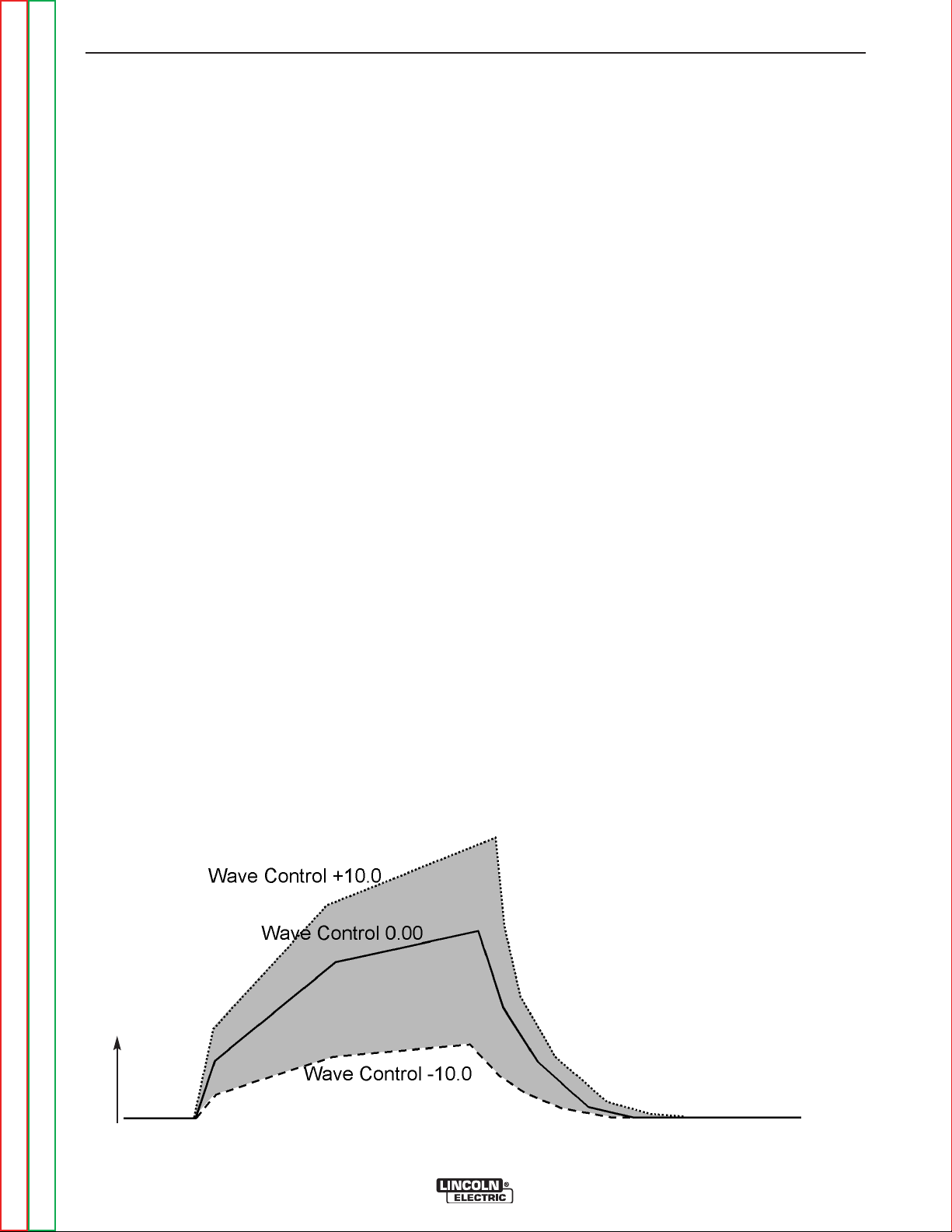
B-5 B-5
OPERATION
In non-synergic modes, the WFS control behaves more
like a conventional CV power source where WFS and
voltage are independent adjustments. Therefore to
maintain the arc characteristics, the operator must
adjust the voltage to compensate for any changes
made to the WFS.
In constant current modes (stick, TIG) this control
adjusts the output current, in amps.
• VOLTS / TRIM:
In constant voltage modes (synergic CV, standard CV)
the control adjusts the welding voltage.
In pulse synergic welding modes (pulse GMAW only)
the user can change the Trim setting to adjust the arc
length. It is adjustable from 0.500 to 1.500. A Trim setting of 1.000 is a good starting point for most conditions.
• WELDING MODE
May be selected by name (CV/MIG, CC/Stick Crisp,
Gouge, etc.) or by a mode number (10, 24, 71, etc.)
depending on the Control Box options. Selecting a
welding mode determines the output characteristics of
the Power Wave power source. A more complete
description of all modes can be found in this section.
• ARC CONTROL
CONSTANT VOLTAGE WELDING
Synergic CV:
For each wire feed speed, a corresponding voltage is
preprogrammed into the machine through special software at the factory. The nominal preprogrammed voltage is the best average voltage for a given wire feed
speed, but may be adjusted to preference. When the
wire feed speed changes, the Power Wave automatically adjusts the voltage level correspondingly to maintain similar arc characteristics throughout the WFS
range.
Non Synergic CV:
This type of CV mode behaves more like a conventional CV power source. Voltage and WFS are independent
adjustments. Therefore to maintain the arc characteristics, the operator must adjust the voltage to compensate for any changes made to the WFS.
All CV Modes:
Arc Control, often referred to as wave control, adjusts
the inductance of the wave shape. The wave control
adjustment is similar to the "pinch" function in that it is
inversely proportional to inductance. Therefore,
increasing wave control greater than 0.0 results in a
harsher, colder arc while decreasing the wave control
to less than 0.0 provides a softer, hotter arc.
(See Figure B.2)
Also known as Inductance or Wave Control. Allows
operator to vary the arc characteristics from "soft" to
"harsh" in all weld modes. It is adjustable from -10.0 to
+10.0, with a nominal setting of 00.0 (The nominal setting of 00.0 may be displayed as OFF on some Power
Feed wire feeder control panels). See the Welding
Mode descriptions for a more detailed explanations of
how the Arc Control affects each mode.
Current
FIGURE B.2
CURRENT WAVE FORM (CV)
Return to Section TOC Return to Section TOC Return to Section TOC Return to Section TOC
Return to Master TOC Return to Master TOC Return to Master TOC Return to Master TOC
POWER WAVE 355M/405M
Page 28

B-6 B-6
OPERATION
TIG GTAW
The TIG mode features continuous control from 5 to
425 amps. The TIG mode can be run in either the
Touch Start TIG or Scratch start mode.
The Arc Control level selects the starting mode.
Between –10 and 0, the Touch Start TIG mode is
selected. The OCV is controlled below 10V and the
short circuit "TIG touch" current is maintained at
approximately 25 amps, independent of the preset
current. When the tungsten is lifted, an arc is initiated
and the output is regulated at the preset value. A setting of 0, results in the most positive arc initiation. A
setting of -10 reduces the start procedure to start the
weld, and from there, to ramp to the welding procedure over a specified amount of time.
A setting above 0 selects a Scratch Start. Full OCV is
available when the arc initiates the output is regulated
to the preset value
Typically starting procedure on a higher “+” setting is
known as a “Hot Start”. Setting a starting procedure
on a lower setting is known as a “Cold Start”.
NOTE: Later versions of weld software
eliminated the Arc Control Function
in TIG mode and only allow for
“Touch Start” operation.
SMAW
In SMAW (STICK mode), the arc control adjusts the
arc force. It can be set to the lower range (0 to -10) for
a soft and less penetrating arc characteristic or to the
higher range (0 to +10) for a crisp and more penetrating arc. Normally, when welding with cellulosic types of
electrodes (E6010, E7010, E6011), a higher energy
arc is required to maintain arc stability. This is usually
indicated when the electrode sticks to the work-piece
or when the arc pops-out during manipulative technique. For low hydrogen types of electrodes (E7018,
E8018, E9018, etc.) a softer arc is usually desirable
and the lower end of the Arc Control suits these types
of electrodes. In either case the arc control is available
to increase or decrease the energy level delivered to
the arc.
Recommended Welding Procedures for Power Mode
TABLE B.2
MATERIAL Aluminum 4043 Aluminum 5356 Mild Steel Mild Steel Mild Steel Mild Steel Mild Steel Mild Steel Stainless Steel Stainless Steel
WIRE E4043 E5356 L56 L56 L56 L56 L56 L56 E308L E308L
WIRE SIZE 0.035 0.035 0.025 0.025 0.030 0.030 0.035 0.035 0.030 0.035
GAS 100% Agr. 100% Agr.
22 ga.
20 ga. 120 / 1.0 120 / 1.0 100 / 0.7 100 / 1.0 80 / 1.5 50 / 0.5
18 ga. 140 / 1.7 140 / 1.5 110 / 1.5 110 / 1.5 100 / 2.5 100 / 2.5 110 / 2.0 110 / 2.0
16 ga. 190 / 2.0 190 / 2.0 125 / 2.0 125 / 2.0 125 / 3.0 125 / 3.0 140 / 2.5 130 / 2.7
14 ga. 400 / 2.0 400 / 2.5 260 / 3.0 260 / 3.0 160 / 2.3 160 / 2.3 160 / 3.8 160 / 3.5 210 / 3.0 190 / 3.5
12 ga. 330 / 5.0 330 / 4.5 230 / 3.5 230 / 3.5 200 / 5.0 200 / 4.5 270 / 5.0 230 / 6.0
MATERIAL THICKNESS
10 ga. 500 / 7.0 500 / 7.0 300 / 6.0 300 / 6.0 240 / 6.5 240 / 7.0 325 / 6.5 300 / 7.0
WFS / POWER MODE SETTING
3/16 570 / 90 600 / 7.8 400 / 7.5 400 / 7.0
1/4 700 / 9.1 700 / 8.5
COMMENTS
Not
Recommended
below 400
WFS
Not
Recommended
below 400
WFS
100% CD275/25 Ar/CO2100% CD275/25 Ar/CO2100% CD275/25 Ar/CO
Not
recommended
100 / 0.8
Not
recommended
90 / 1.0
Tri-mix Tri-mix
2
Return to Section TOC Return to Section TOC Return to Section TOC Return to Section TOC
Return to Master TOC Return to Master TOC Return to Master TOC Return to Master TOC
POWER WAVE 355M/405M
Page 29

B-7 B-7
STEEL BUTTED TOGTHER
WELD GROOVES CREATED BY ARC GOUGING
OPERATION
ARC GOUGING
Gouging is basically removing metal to form a bevel or
groove in a piece of steel with controlled forced air and
a carbon rod.
The common procedures for Arc Gouging metal are:
• Removing poor welds from a weldment so that new
welds can be made.
• Creating a welding groove or grooves in two pieces
of steel butted together. (See Example below)
Power Mode™ is a method of high speed regulation of
the output power whenever an arc is established. It
provides a fast response to changes in the arc. The
higher the Power Mode Setting, the longer the arc. If a
welding procedure is not established, the best way to
determine the Power Mode Setting is by experimentation until the desired output result is established.
In the Power Mode variables need to be set:
• Wire Feed Speed
• Output
• Arc Control
Setting up a Power Mode procedure is similar to setting a CV MIG procedure. Select a shielding gas
appropriate for a short arc process.
• For steel, use 75/25 Ar/CO2 shield gas.
Mode 9 in the POWER WAVE 355M is specifically for
gouging. Gouging can also be done in the stick soft
and crisp modes. Setting the output of the Stick Soft
mode to 425 amps will enable the arc-gouging mode.
The actual output current will depend on the size of
carbon used. The recommended maximum size carbon
is 5/16".
POWER MODE™
The Power Mode™ process was developed by Lincoln
to maintain a stable and smooth arc at low procedure
settings which are needed to weld thin metal without
pop-outs or burning-through. For Aluminum welding, it
provides excellent control and the ability to maintain
constant arc length. This results in improved welding
performance in two primary types of applications.
• Short Arc MIG at low procedure settings.
• Aluminum MIG welding.
• For Stainless, select a Helium blend Tri-Mix.
• For Aluminum, use 100% Ar.
Start by setting the wire feed speed based upon material thickness and appropriate travel speed. Then
adjust the Output knob as follows:
• For steel, listen for the traditional “frying egg”
sound of a good short-arc MIG procedure to know
you have the process set correctly.
• For aluminum, simply adjust the Output knob until
the desired arc length is obtained.
Note the Volts display is simply a relative number and
DOES NOT correspond to voltage.
Some Power Mode procedure recommendations
appear in Table B.2.
Return to Section TOC Return to Section TOC Return to Section TOC Return to Section TOC
Return to Master TOC Return to Master TOC Return to Master TOC Return to Master TOC
POWER WAVE 355M/405M
Page 30
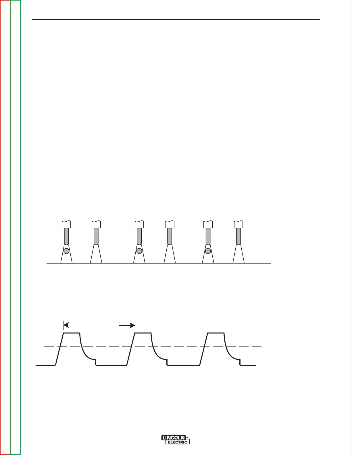
B-8 B-8
PEAK AMPS
FREQUENCY
SPRAY TRANSITION
CURRENT
EACH PULSE DELIVERS ONE DROPLET OF WELD MATERIAL
OPERATION
SPECIAL WELDING PROCESSES
AVAILABLE ON THIS MACHINE
PULSE WELDING (GMAW-P)
The pulsed-arc process is, by definition, a spray transfer process wherein spray transfer occurs in pulses at
regularly spaced intervals. In the time between pulses,
the welding current is reduced and no metal transfer
occurs.
Pulsed-arc transfer is obtained by operating a power
source between low and high current levels. The high
current level or “pulse” forces an electrode drop to the
workpiece. The low current level or “background” maintains the arc between pulses. (See Figure B.3).
Pulsed MIG is an advanced form of welding that takes
the best of all the other forms of transfer while minimizing or eliminating their disadvantages. Unlike short
circuit, pulsed MIG does not create spatter or run the
risk of cold lapping. The welding positions in pulsed
MIG are not limited as they are with globular or spray
and its wire use is definitely more efficient. Unlike the
spray arc process, pulsing offers controlled heat input
that allows better welding on thin materials. Pulsing
allows for lower wire feed speeds which leads to less
distortion and improved overall quality and appearance. This is especially important with stainless, nickel and other alloys that are sensitive to heat input.
In GMAW-P mode, arc control adjusts the background
current and frequency of the wave. When arc control
goes up, the frequency increases thus increasing the
droplet transfer.
FIGURE B.3
Return to Section TOC Return to Section TOC Return to Section TOC Return to Section TOC
Return to Master TOC Return to Master TOC Return to Master TOC Return to Master TOC
POWER WAVE 355M/405M
Page 31

B-9 B-9
OPERATION
PULSE WELDING
Pulse welding procedures are set by controlling an
overall "arc length" variable. When pulse welding, the
arc voltage is highly dependent upon the waveform.
The peak current, back ground current, rise time, fall
time and pulse frequency all affect the voltage. The
exact voltage for a given wire feed speed can only be
predicted when all the pulsing waveform parameters
are known. Using a preset voltage becomes impractical, and instead the arc length is set by adjusting
"trim".
Trim adjusts the arc length and ranges from 0.50 to
1.50, with a nominal value of 1.00. Trim values greater
than 1.00 increase the arc length, while values less
than 1.00 decrease the arc length.
All pulse welding programs are synergic. As the wire
feed speed is adjusted, the Power Wave will automatically recalculate the waveform parameters to maintain
similar arc properties.
The Power Wave utilizes "adaptive control" to compensate for changes in electrical stick out while welding.
(Contact to Work Distance is the distance from the
contact tip to the work piece.) The Power Wave wave
forms are optimized for a 0.75" (19mm) stick-out. The
adaptive behavior supports a range of stickouts from
0.50" (13mm) to 1.25" (32mm). At very low or high wire
feed speeds, the adaptive range may be less due to
reaching physical limitations of the welding process.
FIGURE B.3
CURRENT WAVE FORM (PULSE)
Current
Time
Arc Control, often referred to as wave control, in pulse
programs usually adjusts the focus or shape of the arc.
Wave control values greater than 0.0 increase the
pulse frequency while decreasing the background current, resulting in a tight, stiff arc best for high speed
sheet metal welding. Wave control values less than 0.0
decrease the pulse frequency while increasing the
background current, for a soft arc good for out-of-position welding.
Return to Section TOC Return to Section TOC Return to Section TOC Return to Section TOC
Return to Master TOC Return to Master TOC Return to Master TOC Return to Master TOC
POWER WAVE 355M/405M
Page 32

B-10 B-10
PEAK
AMPS
BACKGROUND
AMPS
TIME
HIGH HEAT
PULSES
LOW HEAT
PULSES
"N" PULSES "N" PULSES
Aluminum 4043 Aluminum 4043 Aluminum 5356 Aluminum 5356
100% Ar. 100% Ar. 100% Ar. 100% Ar.
E4043 E4043 E5356 E5356
0.035 3/64 0.035 3/64
14 ga. 250 / 0 200 / 0 230 / 0 225 / 0
10 ga. 400 / 0 280 / 0 425 / 0 400 / 0
3/16 550 / 0 340 / 0 670 / 0 500 / 0
1/4 600 / 0 400 / 0 700 / 0 550 / 0
WFS /
ARC CONTROL
MATERIAL
THICKNESS
MATERIAL
GAS
WIRE
WIRE SIZE
Not Recommended
below 200 WFS
COMMENTS
Not Recommended
below 200 WFS
Not Recommended
below 100 WFS
Not Recommended
below 200 WFS
OPERATION
PULSE-ON-PULSE™ (GMAW-PP)
Pulse on Pulse™ is a Lincoln process specifically
designed for use in welding relatively thin (less than
1/4" thick) aluminum (See the table below). It gives
weld beads with very consistent uniform ripple.
In Pulse on Pulse modes, two distinct pulse types are
used, instead of the single pulse type normally used in
GMAW-P. A number of high energy pulses are used to
obtain spray transfer and transfer metal across the arc.
Such pulses are shown in the figure below. After a
number "N" of such pulses, depending on the wire feed
speed used, an identical number "N" of low energy
pulses are performed. These low energy pulses, shown
in the figure below, do not transfer any filler metal
across the arc and help to cool the arc and keep the
heat input low.
The Peak Current, Background Current, and
Frequency are identical for the high energy and low
energy pulses. In addition to cooling the weld down, the
major effect of the low energy pulses is that they form
a weld ripple. Since they occur at very regular time
intervals, the weld bead obtained is very uniform with a
very consistent ripple pattern. In fact, the bead has its
best appearance if no oscillation of the welding gun
("whipping") is used.(See the figure below)
When Arc Control is used in the Pulse on Pulse
modes, it does the same things it does in the other
pulsed modes: decreasing the Arc Control decreases
the droplet transfer and weld deposition rate.
Increasing the Arc Control increases the droplet transfer and weld deposition rate. Since Arc Control varies
weld droplet transfer rate, the Arc Control can be used
to vary the ripple spacing in the weld bead.
BENEFITS OF PULSE ON PULSE FROM
LINCOLN ELECTRIC
• Excellent appearance of the weld bead
• Improved cleaning action
• Reduced porosity
Table B.3 shows WFS and Trim settings for common
aluminum types and wire sizes when welding with
Pulse-on-Pulse. The welds made to obtain the values
in the table were fillet welds in the flat position. The values in the table can be helpful as a starting point to
establish a welding procedure. From there, adjustments need to be made to set the proper procedure for
each specific application (out-of-position, other types
of joints, etc.).
The comments on the table below show values of WFS
below which it is not recommended to weld. The reason is, that below these values the weld transfer will
change from a spray arc to a short-arc, which is not
advisable when welding aluminum.
Return to Master TOC Return to Master TOC Return to Master TOC Return to Master TOC
Return to Section TOC Return to Section TOC Return to Section TOC Return to Section TOC
TABLE B.3
WELDING PROCEDURES FOR PULSE-ON-PULSE
POWER WAVE 355M/405M
Page 33

C-1 C-1
Accessories . . . . . . . . . . . . . . . . . . . . . . . . . . . . . . . . . . . . . . . . . . . . . . . . . . . . . . . . . . . . . . . . . . . . . . . . . . . .C-1
Optional Equipment ....................................................................................................................................C-2
TABLE OF CONTENTS - ACCESSORIES SECTION
Field Installed .................................................................................................................................C-2
Compatible Lincoln Equipment ......................................................................................................C-2
Return to Master TOC Return to Master TOC Return to Master TOC Return to Master TOC
POWER WAVE 355M/405M
Page 34

C-2 C-2
ACCESSORIES
OPTIONAL EQUIPMENT
FACTORY INSTALLED
None Available.
FIELD INSTALLED
K940-Work Voltage Sense Lead Kit
K1764-1-Undercarriage*
K1838-1-Valet Style Undercarriage
K1796-Coaxial Welding CableK2176-1 Twist-mate to Lug Adapters
* Dual Cylinder Kit for K1764-1 is K1702-1
K2436-1 Ethernet/Devicenet Communication Interface
Welding Cable Connectors:
K852-70 1/0-2/0 CABLE
K852-95 2/0-3/0 CABLE
COMPATIBLE LINCOLN EQUIPMENT
(Requires Adapter K2176-1)
Any ARC Link compatible wire feeding equipment
PF10M, PF15M, PF25M series.
NOTE: No Linc-Net semi-automatic wire feeding equipment is compatible. Specifically, the semi-automatic
Power Feed family (PF-10, PF-10X2, PF-11) will not
work with a PW355M/405M.
Return to Section TOC Return to Section TOC Return to Section TOC Return to Section TOC
Return to Master TOC Return to Master TOC Return to Master TOC Return to Master TOC
POWER WAVE 355M/405M
Page 35

D-1 D-1
Maintenance . . . . . . . . . . . . . . . . . . . . . . . . . . . . . . . . . . . . . . . . . . . . . . . . . . . . . . . . . . . . . . . . . . . . . . . . . . .D-1
Safety Precautions.......................................................................................................................................D-2
Capacitor Discharge Procedure ..................................................................................................................D-2
Visual Inspection..........................................................................................................................................D-2
Routine Maintenance...................................................................................................................................D-2
Periodic Maintenance ..................................................................................................................................D-2
Major Component Locations .......................................................................................................................D-3
TABLE OF CONTENTS - MAINTENANCE SECTION
Return to Master TOC Return to Master TOC Return to Master TOC Return to Master TOC
POWER WAVE 355M/405M
Page 36

D-2 D-2
CAPACITOR
TERMINALS
RESISTOR
MAINTENANCE
VISUAL INSPECTION
WARNING
Have qualified personnel do the maintenance
wo rk. A l w a y s use the g r e atest c a re when
working near moving parts.
Do not put your hands near the cooling blower
fan. I f a proble m can n o t b e co r recte d by
following the instructions, take the machine to
the nearest Lincoln Field Service Shop.
-----------------------------------------------------------------------
ELECTRIC SHOCK can kill.
• Do not touch electrically live parts or
electrode with skin or wet clothing.
• Insula t e yoursel f f r o m w o r k and
ground
• Always wear dry insulating gloves.
------------------------------------------------------------------------
EXPLODING PARTS can cause
injury.
•
Failed parts can explode or cause other
parts to explode when power is applied.
Always wear a face shield and long sleeves
•
when servicing.
------------------------------------------------------------------------
See a ddi tio na l w arn ing i nfo rma ti on
throughout this Manual.
------------------------------------------------------------------------
Clean interior of machine with a low pressure air
stream. Make a thorough inspection of all components. Look for signs of overheating, broken leads or
other obvious problems. Many problems can be
uncovered with a good visual inspection.
ROUTINE MAINTENANCE
1. Every 6 months or so the machine should be
cleaned with a low pressure airstream. Keeping
the machine clean will result in cooler operation
and higher reliability. Be sure to clean these
areas:
• All printed circuit boards
• Power switch
• Main transformer
• Input rectifier
• Auxiliary Transformer
• Reconnect Switch Area
• Fan (Blow air through the rear louvers)
2. Examine the sheet metal case for dents or breakage.
Repair the case as required. Keep the case in good
condition to insure that high voltage parts are protected
and correct spacings are maintained. All external sheet
metal screws must be in place to insure case strength
and electrical ground continuity.
PERIODIC MAINTENANCE
CAPACITOR DISCHARGE PROCEDURE
1. Obtain a power resistor (25 ohms, 25 watts).
2. Hold resistor body with electrically insulated glove.
DO NOT TOUCH TERMINALS.
tor terminals across the two studs in the position
shown. Hold in each position for 1 second. Repeat
for all four capacitors.
3. Use a DC voltmeter to check that voltage is not
present across the terminals on all four capacitors.
Connect the resis-
Calibration of the POWER WAVE 355M/405M is critical
to its operation. Generally speaking the calibration will
not need adjustment. However, neglected or improperly calibrated machines may not yield satisfactory weld
performance. To ensure optimal performance, the calibration of output Voltage and Current should be
checked yearly.
Calibration is accomplished with our Diagnostic Utility
software found on the Lincoln Electric Service
Navigator CD or on our web site at www.lincoln electric.com.
If a welder has difficulty in being calibrated some things
to look for proper configuration of the sense leads.
Make sure your meter is measuring at the same point
as the power source - local (studs) or remote (feeder).
All meters used for calibration checks must be calibrated and traceable to National Standards. Some digital
meters may not function properly with inverter supplies. Try an analog type meter and calibrate around
300 amps @ 30V loading in all cases.
Return to Section TOC Return to Section TOC Return to Section TOC Return to Section TOC
Return to Master TOC Return to Master TOC Return to Master TOC Return to Master TOC
POWER WAVE 355M/405M
Page 37

D-3 D-3
W
A
R
N
I
N
G
W
A
R
N
I
N
G
A
V
I
S
O
D
E
P
R
E
C
A
U
C
I
O
N
A
T
T
E
N
T
I
O
N
!
!
!
!
L
o
r
e
m
i
p
s
u
m
d
o
l
o
r
s
i
t
a
m
e
t
c
o
n
s
e
c
t
e
t
u
e
r
a
d
i
p
i
s
c
i
n
g
L
o
r
e
m
i
p
s
u
m
d
o
l
o
r
s
i
t
a
m
e
t
c
o
n
s
e
c
t
e
t
u
e
r
a
d
i
p
i
s
c
i
n
g
e
l
i
t
,
e
d
d
i
a
m
n
o
n
u
m
m
y
n
i
b
h
e
u
i
s
m
o
d
t
i
n
c
i
d
u
n
t
u
t
e
l
i
t
,
e
d
d
i
a
m
n
o
n
u
m
m
y
n
i
b
h
e
u
i
s
m
o
d
t
i
n
c
i
d
u
n
t
u
t
l
a
o
r
e
e
t
d
o
l
o
r
e
m
a
g
n
a
a
l
i
q
u
a
m
e
r
a
t
l
a
o
r
e
e
t
d
o
l
o
r
e
m
a
g
n
a
a
l
i
q
u
a
m
e
r
a
t
L
o
r
e
m
i
p
s
u
m
d
o
l
o
r
s
i
t
a
m
e
t
c
o
n
s
e
c
t
e
t
u
e
r
a
d
i
p
i
s
c
i
n
g
L
o
r
e
m
i
p
s
u
m
d
o
l
o
r
s
i
t
a
m
e
t
c
o
n
s
e
c
t
e
t
u
e
r
a
d
i
p
i
s
c
i
n
g
e
l
i
t
,
e
d
d
i
a
m
n
o
n
u
m
m
y
n
i
b
h
e
u
i
s
m
o
d
t
i
n
c
i
d
u
n
t
u
t
e
l
i
t
,
e
d
d
i
a
m
n
o
n
u
m
m
y
n
i
b
h
e
u
i
s
m
o
d
t
i
n
c
i
d
u
n
t
u
t
l
a
o
r
e
e
t
d
o
l
o
r
e
m
a
g
n
a
a
l
i
q
u
a
m
e
r
a
t
l
a
o
r
e
e
t
d
o
l
o
r
e
m
a
g
n
a
a
l
i
q
u
a
m
e
r
a
t
L
o
r
e
m
i
p
s
u
m
d
o
l
o
r
s
i
t
a
m
e
t
c
o
n
s
e
c
t
e
t
u
e
r
a
d
i
p
i
s
c
i
n
g
L
o
r
e
m
i
p
s
u
m
d
o
l
o
r
s
i
t
a
m
e
t
c
o
n
s
e
c
t
e
t
u
e
r
a
d
i
p
i
s
c
i
n
g
e
l
i
t
,
e
d
d
i
a
m
n
o
n
u
m
m
y
n
i
b
h
e
u
i
s
m
o
d
t
i
n
c
i
d
u
n
t
u
t
e
l
i
t
,
e
d
d
i
a
m
n
o
n
u
m
m
y
n
i
b
h
e
u
i
s
m
o
d
t
i
n
c
i
d
u
n
t
u
t
l
a
o
r
e
e
t
d
o
l
o
r
e
m
a
g
n
a
a
l
i
q
u
a
m
e
r
a
t
l
a
o
r
e
e
t
d
o
l
o
r
e
m
a
g
n
a
a
l
i
q
u
a
m
e
r
a
t
L
o
r
e
m
i
p
s
u
m
d
o
l
o
r
s
i
t
a
m
e
t
c
o
n
s
e
c
t
e
t
u
e
r
a
d
i
p
i
s
c
i
n
g
L
o
r
e
m
i
p
s
u
m
d
o
l
o
r
s
i
t
a
m
e
t
c
o
n
s
e
c
t
e
t
u
e
r
a
d
i
p
i
s
c
i
n
g
e
l
i
t
,
e
d
d
i
a
m
n
o
n
u
m
m
y
n
i
b
h
e
u
i
s
m
o
d
t
i
n
c
i
d
u
n
t
u
t
e
l
i
t
,
e
d
d
i
a
m
n
o
n
u
m
m
y
n
i
b
h
e
u
i
s
m
o
d
t
i
n
c
i
d
u
n
t
u
t
l
a
o
r
e
e
t
d
o
l
o
r
e
m
a
g
n
a
a
l
i
q
u
a
m
e
r
a
t
l
a
o
r
e
e
t
d
o
l
o
r
e
m
a
g
n
a
a
l
i
q
u
a
m
e
r
a
t
L
o
r
e
m
i
p
s
u
m
d
o
l
o
r
s
i
t
a
m
e
t
c
o
n
s
e
c
t
e
t
u
e
r
a
d
i
p
i
s
c
i
n
g
L
o
r
e
m
i
p
s
u
m
d
o
l
o
r
s
i
t
a
m
e
t
c
o
n
s
e
c
t
e
t
u
e
r
a
d
i
p
i
s
c
i
n
g
e
l
i
t
,
e
d
d
i
a
m
n
o
n
u
m
m
y
n
i
b
h
e
u
i
s
m
o
d
t
i
n
c
i
d
u
n
t
u
t
e
l
i
t
,
e
d
d
i
a
m
n
o
n
u
m
m
y
n
i
b
h
e
u
i
s
m
o
d
t
i
n
c
i
d
u
n
t
u
t
l
a
o
r
e
e
t
d
o
l
o
r
e
m
a
g
n
a
a
l
i
q
u
a
m
e
r
a
t
l
a
o
r
e
e
t
d
o
l
o
r
e
m
a
g
n
a
a
l
i
q
u
a
m
e
r
a
t
L
o
r
e
m
i
p
s
u
m
d
o
l
o
r
s
i
t
a
m
e
t
c
o
n
s
e
c
t
e
t
u
e
r
a
d
i
p
i
s
c
i
n
g
L
o
r
e
m
i
p
s
u
m
d
o
l
o
r
s
i
t
a
m
e
t
c
o
n
s
e
c
t
e
t
u
e
r
a
d
i
p
i
s
c
i
n
g
e
l
i
t
,
e
d
d
i
a
m
n
o
n
u
m
m
y
n
i
b
h
e
u
i
s
m
o
d
t
i
n
c
i
d
u
n
t
u
t
e
l
i
t
,
e
d
d
i
a
m
n
o
n
u
m
m
y
n
i
b
h
e
u
i
s
m
o
d
t
i
n
c
i
d
u
n
t
u
t
l
a
o
r
e
e
t
d
o
l
o
r
e
m
a
g
n
a
a
l
i
q
u
a
m
e
r
a
t
l
a
o
r
e
e
t
d
o
l
o
r
e
m
a
g
n
a
a
l
i
q
u
a
m
e
r
a
t
L
o
r
e
m
i
p
s
u
m
d
o
l
o
r
s
i
t
a
m
e
t
c
o
n
s
e
c
t
e
t
u
e
r
a
d
i
p
i
s
c
i
n
g
L
o
r
e
m
i
p
s
u
m
d
o
l
o
r
s
i
t
a
m
e
t
c
o
n
s
e
c
t
e
t
u
e
r
a
d
i
p
i
s
c
i
n
g
e
l
i
t
,
e
d
d
i
a
m
n
o
n
u
m
m
y
n
i
b
h
e
u
i
s
m
o
d
t
i
n
c
i
d
u
n
t
u
t
e
l
i
t
,
e
d
d
i
a
m
n
o
n
u
m
m
y
n
i
b
h
e
u
i
s
m
o
d
t
i
n
c
i
d
u
n
t
u
t
l
a
o
r
e
e
t
d
o
l
o
r
e
m
a
g
n
a
a
l
i
q
u
a
m
e
r
a
t
l
a
o
r
e
e
t
d
o
l
o
r
e
m
a
g
n
a
a
l
i
q
u
a
m
e
r
a
t
L
o
r
e
m
i
p
s
u
m
d
o
l
o
r
s
i
t
a
m
e
t
c
o
n
s
e
c
t
e
t
u
e
r
a
d
i
p
i
s
c
i
n
g
L
o
r
e
m
i
p
s
u
m
d
o
l
o
r
s
i
t
a
m
e
t
c
o
n
s
e
c
t
e
t
u
e
r
a
d
i
p
i
s
c
i
n
g
e
l
i
t
,
e
d
d
i
a
m
n
o
n
u
m
m
y
n
i
b
h
e
u
i
s
m
o
d
t
i
n
c
i
d
u
n
t
u
t
e
l
i
t
,
e
d
d
i
a
m
n
o
n
u
m
m
y
n
i
b
h
e
u
i
s
m
o
d
t
i
n
c
i
d
u
n
t
u
t
l
a
o
r
e
e
t
d
o
l
o
r
e
m
a
g
n
a
a
l
i
q
u
a
m
e
r
a
t
l
a
o
r
e
e
t
d
o
l
o
r
e
m
a
g
n
a
a
l
i
q
u
a
m
e
r
a
t
L
o
r
e
m
i
p
s
u
m
d
o
l
o
r
s
i
t
a
m
e
t
c
o
n
s
e
c
t
e
t
u
e
r
a
d
i
p
i
s
c
i
n
g
L
o
r
e
m
i
p
s
u
m
d
o
l
o
r
s
i
t
a
m
e
t
c
o
n
s
e
c
t
e
t
u
e
r
a
d
i
p
i
s
c
i
n
g
e
l
i
t
,
e
d
d
i
a
m
n
o
n
u
m
m
y
n
i
b
h
e
u
i
s
m
o
d
t
i
n
c
i
d
u
n
t
u
t
e
l
i
t
,
e
d
d
i
a
m
n
o
n
u
m
m
y
n
i
b
h
e
u
i
s
m
o
d
t
i
n
c
i
d
u
n
t
u
t
l
a
o
r
e
e
t
d
o
l
o
r
e
m
a
g
n
a
a
l
i
q
u
a
m
e
r
a
t
l
a
o
r
e
e
t
d
o
l
o
r
e
m
a
g
n
a
a
l
i
q
u
a
m
e
r
a
t
L
o
r
e
m
i
p
s
u
m
d
o
l
o
r
s
i
t
a
m
e
t
c
o
n
s
e
c
t
e
t
u
e
r
a
d
i
p
i
s
c
i
n
g
L
o
r
e
m
i
p
s
u
m
d
o
l
o
r
s
i
t
a
m
e
t
c
o
n
s
e
c
t
e
t
u
e
r
a
d
i
p
i
s
c
i
n
g
e
l
i
t
,
e
d
d
i
a
m
n
o
n
u
m
m
y
n
i
b
h
e
u
i
s
m
o
d
t
i
n
c
i
d
u
n
t
u
t
e
l
i
t
,
e
d
d
i
a
m
n
o
n
u
m
m
y
n
i
b
h
e
u
i
s
m
o
d
t
i
n
c
i
d
u
n
t
u
t
l
a
o
r
e
e
t
d
o
l
o
r
e
m
a
g
n
a
a
l
i
q
u
a
m
e
r
a
t
l
a
o
r
e
e
t
d
o
l
o
r
e
m
a
g
n
a
a
l
i
q
u
a
m
e
r
a
t
L
o
r
e
m
i
p
s
u
m
d
o
l
o
r
s
i
t
a
m
e
t
c
o
n
s
e
c
t
e
t
u
e
r
a
d
i
p
i
s
c
i
n
g
L
o
r
e
m
i
p
s
u
m
d
o
l
o
r
s
i
t
a
m
e
t
c
o
n
s
e
c
t
e
t
u
e
r
a
d
i
p
i
s
c
i
n
g
e
l
i
t
,
e
d
d
i
a
m
n
o
n
u
m
m
y
n
i
b
h
e
u
i
s
m
o
d
t
i
n
c
i
d
u
n
t
u
t
e
l
i
t
,
e
d
d
i
a
m
n
o
n
u
m
m
y
n
i
b
h
e
u
i
s
m
o
d
t
i
n
c
i
d
u
n
t
u
t
l
a
o
r
e
e
t
d
o
l
o
r
e
m
a
g
n
a
a
l
i
q
u
a
m
e
r
a
t
l
a
o
r
e
e
t
d
o
l
o
r
e
m
a
g
n
a
a
l
i
q
u
a
m
e
r
a
t
L
o
r
e
m
i
p
s
u
m
d
o
l
o
r
s
i
t
a
m
e
t
c
o
n
s
e
c
t
e
t
u
e
r
a
d
i
p
i
s
c
i
n
g
L
o
r
e
m
i
p
s
u
m
d
o
l
o
r
s
i
t
a
m
e
t
c
o
n
s
e
c
t
e
t
u
e
r
a
d
i
p
i
s
c
i
n
g
e
l
i
t
,
e
d
d
i
a
m
n
o
n
u
m
m
y
n
i
b
h
e
u
i
s
m
o
d
t
i
n
c
i
d
u
n
t
u
t
e
l
i
t
,
e
d
d
i
a
m
n
o
n
u
m
m
y
n
i
b
h
e
u
i
s
m
o
d
t
i
n
c
i
d
u
n
t
u
t
l
a
o
r
e
e
t
d
o
l
o
r
e
m
a
g
n
a
a
l
i
q
u
a
m
e
r
a
t
l
a
o
r
e
e
t
d
o
l
o
r
e
m
a
g
n
a
a
l
i
q
u
a
m
e
r
a
t
L
o
r
e
m
i
p
s
u
m
d
o
l
o
r
s
i
t
a
m
e
t
c
o
n
s
e
c
t
e
t
u
e
r
a
d
i
p
i
s
c
i
n
g
L
o
r
e
m
i
p
s
u
m
d
o
l
o
r
s
i
t
a
m
e
t
c
o
n
s
e
c
t
e
t
u
e
r
a
d
i
p
i
s
c
i
n
g
e
l
i
t
,
e
d
d
i
a
m
n
o
n
u
m
m
y
n
i
b
h
e
u
i
s
m
o
d
t
i
n
c
i
d
u
n
t
u
t
e
l
i
t
,
e
d
d
i
a
m
n
o
n
u
m
m
y
n
i
b
h
e
u
i
s
m
o
d
t
i
n
c
i
d
u
n
t
u
t
l
a
o
r
e
e
t
d
o
l
o
r
e
m
a
g
n
a
a
l
i
q
u
a
m
e
r
a
t
l
a
o
r
e
e
t
d
o
l
o
r
e
m
a
g
n
a
a
l
i
q
u
a
m
e
r
a
t
L
o
r
e
m
i
p
s
u
m
d
o
l
o
r
s
i
t
a
m
e
t
c
o
n
s
e
c
t
e
t
u
e
r
a
d
i
p
i
s
c
i
n
g
L
o
r
e
m
i
p
s
u
m
d
o
l
o
r
s
i
t
a
m
e
t
c
o
n
s
e
c
t
e
t
u
e
r
a
d
i
p
i
s
c
i
n
g
e
l
i
t
,
e
d
d
i
a
m
n
o
n
u
m
m
y
n
i
b
h
e
u
i
s
m
o
d
t
i
n
c
i
d
u
n
t
u
t
e
l
i
t
,
e
d
d
i
a
m
n
o
n
u
m
m
y
n
i
b
h
e
u
i
s
m
o
d
t
i
n
c
i
d
u
n
t
u
t
l
a
o
r
e
e
t
d
o
l
o
r
e
m
a
g
n
a
a
l
i
q
u
a
m
e
r
a
t
l
a
o
r
e
e
t
d
o
l
o
r
e
m
a
g
n
a
a
l
i
q
u
a
m
e
r
a
t
L
o
r
e
m
i
p
s
u
m
d
o
l
o
r
s
i
t
a
m
e
t
c
o
n
s
e
c
t
e
t
u
e
r
a
d
i
p
i
s
c
i
n
g
L
o
r
e
m
i
p
s
u
m
d
o
l
o
r
s
i
t
a
m
e
t
c
o
n
s
e
c
t
e
t
u
e
r
a
d
i
p
i
s
c
i
n
g
e
l
i
t
,
e
d
d
i
a
m
n
o
n
u
m
m
y
n
i
b
h
e
u
i
s
m
o
d
t
i
n
c
i
d
u
n
t
u
t
e
l
i
t
,
e
d
d
i
a
m
n
o
n
u
m
m
y
n
i
b
h
e
u
i
s
m
o
d
t
i
n
c
i
d
u
n
t
u
t
l
a
o
r
e
e
t
d
o
l
o
r
e
m
a
g
n
a
a
l
i
q
u
a
m
e
r
a
t
l
a
o
r
e
e
t
d
o
l
o
r
e
m
a
g
n
a
a
l
i
q
u
a
m
e
r
a
t
L
o
r
e
m
i
p
s
u
m
d
o
l
o
r
s
i
t
a
m
e
t
c
o
n
s
e
c
t
e
t
u
e
r
a
d
i
p
i
s
c
i
n
g
L
o
r
e
m
i
p
s
u
m
d
o
l
o
r
s
i
t
a
m
e
t
c
o
n
s
e
c
t
e
t
u
e
r
a
d
i
p
i
s
c
i
n
g
e
l
i
t
,
e
d
d
i
a
m
n
o
n
u
m
m
y
n
i
b
h
e
u
i
s
m
o
d
t
i
n
c
i
d
u
n
t
u
t
e
l
i
t
,
e
d
d
i
a
m
n
o
n
u
m
m
y
n
i
b
h
e
u
i
s
m
o
d
t
i
n
c
i
d
u
n
t
u
t
l
a
o
r
e
e
t
d
o
l
o
r
e
m
a
g
n
a
a
l
i
q
u
a
m
e
r
a
t
l
a
o
r
e
e
t
d
o
l
o
r
e
m
a
g
n
a
a
l
i
q
u
a
m
e
r
a
t
L
o
r
e
m
i
p
s
u
m
d
o
l
o
r
s
i
t
a
m
e
t
c
o
n
s
e
c
t
e
t
u
e
r
a
d
i
p
i
s
c
i
n
g
L
o
r
e
m
i
p
s
u
m
d
o
l
o
r
s
i
t
a
m
e
t
c
o
n
s
e
c
t
e
t
u
e
r
a
d
i
p
i
s
c
i
n
g
e
l
i
t
,
e
d
d
i
a
m
n
o
n
u
m
m
y
n
i
b
h
e
u
i
s
m
o
d
t
i
n
c
i
d
u
n
t
u
t
e
l
i
t
,
e
d
d
i
a
m
n
o
n
u
m
m
y
n
i
b
h
e
u
i
s
m
o
d
t
i
n
c
i
d
u
n
t
u
t
l
a
o
r
e
e
t
d
o
l
o
r
e
m
a
g
n
a
a
l
i
q
u
a
m
e
r
a
t
l
a
o
r
e
e
t
d
o
l
o
r
e
m
a
g
n
a
a
l
i
q
u
a
m
e
r
a
t
L
o
r
e
m
i
p
s
u
m
d
o
l
o
r
s
i
t
a
m
e
t
c
o
n
s
e
c
t
e
t
u
e
r
a
d
i
p
i
s
c
i
n
g
L
o
r
e
m
i
p
s
u
m
d
o
l
o
r
s
i
t
a
m
e
t
c
o
n
s
e
c
t
e
t
u
e
r
a
d
i
p
i
s
c
i
n
g
e
l
i
t
,
e
d
d
i
a
m
n
o
n
u
m
m
y
n
i
b
h
e
u
i
s
m
o
d
t
i
n
c
i
d
u
n
t
u
t
e
l
i
t
,
e
d
d
i
a
m
n
o
n
u
m
m
y
n
i
b
h
e
u
i
s
m
o
d
t
i
n
c
i
d
u
n
t
u
t
l
a
o
r
e
e
t
d
o
l
o
r
e
m
a
g
n
a
a
l
i
q
u
a
m
e
r
a
t
l
a
o
r
e
e
t
d
o
l
o
r
e
m
a
g
n
a
a
l
i
q
u
a
m
e
r
a
t
L
o
r
e
m
i
p
s
u
m
d
o
l
o
r
s
i
t
a
m
e
t
c
o
n
s
e
c
t
e
t
u
e
r
a
d
i
p
i
s
c
i
n
g
L
o
r
e
m
i
p
s
u
m
d
o
l
o
r
s
i
t
a
m
e
t
c
o
n
s
e
c
t
e
t
u
e
r
a
d
i
p
i
s
c
i
n
g
e
l
i
t
,
e
d
d
i
a
m
n
o
n
u
m
m
y
n
i
b
h
e
u
i
s
m
o
d
t
i
n
c
i
d
u
n
t
u
t
e
l
i
t
,
e
d
d
i
a
m
n
o
n
u
m
m
y
n
i
b
h
e
u
i
s
m
o
d
t
i
n
c
i
d
u
n
t
u
t
l
a
o
r
e
e
t
d
o
l
o
r
e
m
a
g
n
a
a
l
i
q
u
a
m
e
r
a
t
l
a
o
r
e
e
t
d
o
l
o
r
e
m
a
g
n
a
a
l
i
q
u
a
m
e
r
a
t
W
A
R
N
I
N
G
R
E
M
O
T
E
P
O
W
E
R
O
F
F
O
N
S
T
A
T
U
S
T
H
E
R
M
A
L
LI
N
C
O
LN
E
LE
C
TR
I
C
P
O
WE
R
W
A
V
E
3
5
5
2
0
7
2
0
9
5
2
3
1
4
MAINTENANCE
FIGURE D.1 – MAJOR COMPONENT LOCATIONS
1. Center Panel
2. Case Back
3. Case Front
4. Base Assembly
5. Case Wraparound
Use parts page exploded views to also help isolate and identify smaller parts. Parts page numbers can be found on the Master Table of
Contents in the front of this manual.
Return to Section TOC Return to Section TOC Return to Section TOC Return to Section TOC
Return to Master TOC Return to Master TOC Return to Master TOC Return to Master TOC
POWER WAVE 355M/405M
Page 38

D-4 D-4
NOTES
Return to Section TOC Return to Section TOC Return to Section TOC Return to Section TOC
Return to Master TOC Return to Master TOC Return to Master TOC Return to Master TOC
POWER WAVE 355M/405M
Page 39

E-1 E-1
Control Board
Choke
Positive
Output
Terminal
Negative
Output
Terminal
To Control
Board
Cur
r
ent
Feedbac
k
Reconnect
Switch
O
u
t
p
u
t
V
o
l
t
a
g
e
Se
n
se
Input switch
Input
Rectifier
Auxiliary
Transformer
Fan
Power
Board
220
Receptacle
RS232 Supply +5VDC
Machine Control Supply
+15VDC, -15VDC, +5VDC
40VDC
42VAC
220 VAC
Main Switch Board
115VAC Fan Supply
F
a
n
Co
n
t
ro
l
V/F Capacitor Feedback (2)
Soft Start Control
Input Relay Control
Primary Current Feedback(2)
IGB
T D
r
i
ve
S
i
g
n
a
l
P
rimary
Current
S
ensor
Primary
C
urrent
Sensor
{
P
o
w
e
r
W
a
v
e
4
0
5
o
n
l
y
65VAC
DC
Bus
Board
Wire
Feeder
Recp.
40VDC
Can Supply +5VDC
Arc
Link
Electrode
Sense
21 Lead
Voltage
Sense
Recp.
R232
Connector
Yellow
Thermal
LED
Status
Red/Green
LED
Thermostats
2
To
Feeder
TABLE OF CONTENTS-THEORY OF OPERATION SECTION
Theory of Operation . . . . . . . . . . . . . . . . . . . . . . . . . . . . . . . . . . . . . . . . . . . . . . . . . . . . . . . . . . . . . . . . . . . . .E-1
General Description ...................................................................................................................................E-2
Input Line Voltage, Auxiliary Transformer and Precharge..........................................................................E-2
Switch Board and Main Transformer .........................................................................................................E-3
DC Bus Board, Power board and Control Board ......................................................................................E-4
Output Rectifier and Choke .......................................................................................................................E-5
Thermal Protection ...................................................................................................................................E-6
Protective Circuits......................................................................................................................................E-6
Over current Protection .......................................................................................................................E-6
Under/Over Voltage Protection ...........................................................................................................E-6
Insulated Gate Bipolar Transistor (IGBT) Operation ..................................................................................E-7
Pulse Width Modulation.............................................................................................................................E-8
Return to Master TOC Return to Master TOC Return to Master TOC Return to Master TOC
Minimum/Maximum Output ................................................................................................................E-8
FIGURE E.1 BLOCK LOGIC DIAGRAM
POWER WAVE 355M/405M
Page 40

E-2 E-2
C
ontrol Board
C
hoke
Positive
Output
Terminal
Negative
Output
Terminal
To Control
Board
C
u
rre
n
t
Fe
e
d
b
a
c
k
Reconnect
Switch
Output V
ol
tage Sense
Input switch
Input
Rectifier
Auxiliary
Transformer
F
an
Power
Board
220
Receptacle
RS232 Supply +5VDC
Machine Control Supply
+
15VDC, -15VDC, +5VDC
40VDC
42VAC
220 VAC
M
ain Switch Board
115VAC Fan Supply
Fa
n
Co
n
tro
l
V
/F Capacitor Feedback (2)
Soft Start Control
Input Relay Control
P
rimary Current Feedback(2)
I
G
B
T
Dr
i
ve
S
i
g
n
a
l
Primary
C
urrent
Sensor
Primary
C
urrent
Sensor
{
P
o
w
e
r
W
a
v
e
4
0
5
o
n
l
y
6
5
VAC
D
C
Bus
Board
Wire
F
eeder
Recp.
40VDC
C
an Supply +5VDC
Arc
Link
Electrode
Sense
21 Lead
V
oltage
Sense
Recp.
R232
Connector
Yellow
Thermal
LED
Status
Red/Green
LED
Thermostats
2
THEORY OF OPERATION
FIGURE E.2 - GENERAL DISCRIPTION
Return to Section TOC Return to Section TOC Return to Section TOC Return to Section TOC
GENERAL DESCRIPTION
The Power Wave semi-automatic power source is
designed to be a part of a modular, multi-process
welding system. Depending on configuration, it can
support constant current, constant voltage, and pulse
welding modes.
The Power Wave power source is designed to be used
with the semi-automatic family of power feed wire
feeders, operating as a system. Each component in
the system has special circuitry to “talk with” the other
system components, so each component (power
source, wire feeder, user interface) knows what the
other is doing at all times. These components communicate with Arc Link (a digital communications system).
The POWER WAVE 355M/405M is a high performance,
digitally controlled inverter welding power source
capable of complex, high speed waveform control.
Properly equipped, it can support the GMAW, GMAWP, FCAW, SMAW, GTAW, and CAC-A processes. It carries an output rating of 350 Amps, 34 Volts at 60%
duty cycle and 300 Amps, 32 volts at 100% duty cycle.
INPUT LINE VOLTAGE, AUXILIARY
TRANSFORMER, & PRECHARGE
The POWER WAVE 355M/405M can be connected for
a variety of three-phase or single-phase input voltages. The initial power is applied to the 355M/405M
through a line switch located on the front of the
machine. Two phases of the input voltage are applied
to the auxiliary transformer. The auxiliary transformer
Return to Master TOC Return to Master TOC Return to Master TOC Return to Master TOC
develops three different secondary voltages. The
115VAC is applied, via the main switch board, to the
fan motor. The 42VAC is rectified and filtered. The
65VDC produced by the Bus board rectifier is used by
the Bus board to provide 40VDC to the power board.
40VDC is also applied to the wire feeder receptacle.
PW405 models have an additional 220VAC winding
that is connected to a 220 AC receptacle.
The input voltage is rectified by the input rectifier and
the resultant DC voltage is applied to the switch board
through the reconnect switch assembly located at the
rear of the machine. The reconnect switch connects
the two pairs of input capacitors either in a parallel
(lower voltage) or series (higher voltage) configuration
to accommodate the applied input voltage.
During the precharge time the DC input voltage is
applied to the input capacitors through a current limiting circuit. The input capacitors are charged slowly
and current limited. A voltage to frequency converter
circuit located on the switch board monitors the
capacitor voltages. This signal is coupled to the control board. When the input capacitors have charged
to an acceptable level, the control board energizes the
input relays, that are located on the switch board,
making all of the input power, without current limiting,
available to the input capacitors. If the capacitors
become under or over voltage the control board will
de-energize the input relays and the 355M/405M output will be disabled. Other possible faults may also
cause the input relays to drop out.
NOTE: Unshaded areas of Block Logic
Diagram are the subject of discussion
POWER WAVE 355M/405M
Page 41

E-3 E-3
C
ontrol Board
C
hoke
P
ositive
Output
Terminal
Negative
Output
Terminal
To Control
Board
C
u
rre
n
t
F
e
e
d
b
a
c
k
Reconnect
Switch
Out
p
ut
Vo
lt
a
ge
S
en
s
e
Input switch
Input
Rectifier
Auxiliary
Transformer
Fan
Power
Board
220
Receptacle
RS232 Supply +5VDC
Machine Control Supply
+15VDC, -15VDC, +5VDC
40VDC
42VAC
220 VAC
M
ain Switch Board
115VAC Fan Supply
Fa
n
Co
n
t
r
o
l
V/F Capacitor Feedback (2)
Soft Start Control
Input Relay Control
P
rimary Current Feedback(2)
I
G
B
T
D
r
i
v
e
S
i
g
n
a
l
P
rimary
Current
S
ensor
Primary
C
urrent
S
ensor
{
P
o
w
e
r
W
a
v
e
4
0
5
o
n
l
y
65VAC
DC
Bus
Board
Wire
Feeder
Recp.
40VDC
Can Supply +5VDC
Arc
Link
Electrode
S
ense
2
1 Lead
Voltage
Sense
Recp.
R232
Connector
Yellow
T
hermal
LED
Status
Red/Green
LED
Thermostats
2
To
THEORY OF OPERATION
FIGURE E.3 – SWITCH BOARD & MAIN TRANSFORMER
Return to Section TOC Return to Section TOC Return to Section TOC Return to Section TOC
SWITCH BOARD &
MAIN TRANSFORMER
There is one switch board in the POWER WAVE
355M/405M. This board incorporates two pairs of
input capacitors, two insulated gate bipolar transistor
(IGBT) switching circuits, a fan motor drive circuit, and
a voltage/frequency capacitor feedback circuit. The
two capacitors in a pair are always in series with each
other. When the reconnect switch is in the lower voltage position the capacitor pairs are in parallel - that is,
two series capacitors in parallel with two series capacitors. When the reconnect switch is in the high voltage
position the two capacitor pairs are in series or, four
capacitors in series. This is required to accommodate
the higher input voltages.
When the input capacitors are fully charged they act
as power supplies for the IGBT switching circuits.
When welding output is required the Insulated Gate
Bipolar Transistors switch the DC power from the input
capacitors, "on and off" thus supplying a pulsed DC
current to the main transformer primary windings. See
Return to Master TOC Return to Master TOC Return to Master TOC Return to Master TOC
IGBT Operation Discussion and Diagrams in this
section. Each IGBT switching circuit feeds current to
a separate, oppositely wound primary winding in the
main transformer. The reverse directions of current
flow through the main transformer primaries and the
offset timing of the IGBT switching circuits induce an
AC square wave output signal at the secondary of the
main transformer. The two current transformers (CT)
located on the switch board monitor these primary
currents. If the primary currents become abnormally
high the control board will shut off the IGBTs, thus disabling the machine output. The DC current flow
through each primary winding is clamped back to
each respective input capacitor when the IGBTs are
turned off. This is needed due to the inductance of the
transformer primary winding. The firing of the two
switch boards occurs during halves of a 50 microsecond interval, creating a constant 20 KHZ output. In
some low open circuit Tig modes the firing frequency
is reduced to 5KHZ.
The POWER WAVE 355M/405M has a F.A.N. (fan as
needed) circuit. The fan operates when the welding
output terminals are energized or when a thermal over
temperature condition exists. Once the fan is activated it will remain on for a minimum of five minutes. The
fan driver circuit is housed on the switch board but it
is activated by a signal from the control board.
NOTE: Unshaded areas of Block Logic
POWER WAVE 355M/405M
Diagram are the subject of discussion
Page 42

E-4 E-4
Control Board
C
hoke
Positive
Output
Terminal
N
egative
Output
Terminal
To Control
Board
C
u
r
r
e
n
t
F
e
e
d
b
a
ck
R
econnect
Switch
O
u
t
p
u
t
V
o
lt
a
g
e
S
e
n
s
e
Input switch
Input
Rectifier
Auxiliary
Transformer
F
an
Power
Board
220
Receptacle
RS232 Supply +5VDC
Machine Control Supply
+15VDC, -15VDC, +5VDC
40VDC
42VAC
220 VAC
M
ain Switch Board
115VAC Fan Supply
F
an C
ontr
ol
V/F Capacitor Feedback (2)
Soft Start Control
Input Relay Control
P
rimary Current Feedback(2)
IG
B
T
Drive
S
ig
n
a
l
Primary
C
urrent
S
ensor
P
rimary
Current
S
ensor
{
P
o
w
e
r
W
a
v
e
4
0
5
o
n
l
y
65VAC
DC
Bus
Board
Wire
Feeder
Recp.
40VDC
Can Supply +5VDC
A
rc
Link
Electrode
Sense
21 Lead
Voltage
Sense
Recp.
R232
C
onnector
Yellow
Thermal
LED
Status
Red/Green
LED
Thermostats
2
To
Feeder
THEORY OF OPERATION
FIGURE E.4 – POWER BOARD, CONTROL BOARD AND SERIAL PERIPHERAL INTERFACE (SPI) COMMUNICATIONS
Return to Section TOC Return to Section TOC Return to Section TOC Return to Section TOC
DC BUS BOARD, POWER BOARD
AND CONTROL BOARD
DC BUS BOARD
The DC Bus Board receives approximately 65VDC
from the bus board rectifier. The DC Bus Board regulates that 65VDC to a +40VDC supply. This regulated
40VDC is applied to the Power Board and the wire
feed receptacles.
POWER BOARD
The power board, utilizing a switching power supply,
processes the 40VDC input and develops several regulated positive and negative DC supplies. Three DC
supplies are fed to the control board for machine control supplies. A +5VDC is used for the RS232 connection supply. Another +5VDC supply is utilized by the
CAN digital communication circuitry. An over or under
input voltage detection and shutdown circuit is also
part of the power board’s circuitry.
Return to Master TOC Return to Master TOC Return to Master TOC Return to Master TOC
NOTE: Unshaded areas of Block Logic
Diagram are the subject of discussion
CONTROL BOARD
The Control Board performs the primary interfacing
functions to establish and maintain output control of
the POWER WAVE 355M/405M. The function generator and weld files exist within the Control Board hardware and software. Digital command signals received
POWER WAVE 355M/405M
from the user interface/feed head and feedback information received from the current sensor and output
voltage sensing leads, are processed at the control
board. Software within the control board processes
the command and feedback information and sends the
appropriate pulse width modulation (PWM) signals
(See PULSE WIDTH MODULATION in this section) to
the switch board IGBT’s. In this manner, the digitally
controlled high speed welding waveform is created.
In addition, the Control Board monitors the thermostats, the main transformer primary currents and
input filter capacitor voltages. Depending on the fault
condition, the Control Board will activate the thermal
and/or the status light and will disable or reduce the
machine’s output.
Page 43

E-5 E-5
C
ontrol Board
Choke
Positive
O
utput
T
erminal
Negative
O
utput
Terminal
To Control
Board
C
u
r
r
e
n
t
F
e
e
d
b
a
ck
Reconnect
Switch
Ou
t
p
u
t
V
o
lt
a
g
e
S
e
n
s
e
Input switch
Input
Rectifier
Auxiliary
Transformer
Fan
Power
Board
220
Receptacle
RS232 Supply +5VDC
Machine Control Supply
+15VDC, -15VDC, +5VDC
40VDC
42VAC
220 VAC
M
ain Switch Board
115VAC Fan Supply
F
a
n
C
o
n
tr
o
l
V
/F Capacitor Feedback (2)
Soft Start Control
I
nput Relay Control
Primary Current Feedback(2)
IG
B
T
Drive
S
ig
n
a
l
P
rimary
Current
Sensor
Primary
Current
S
ensor
{
P
o
w
e
r
W
a
v
e
4
0
5
o
n
l
y
65VAC
DC
Bus
Board
Wire
Feeder
Recp.
40VDC
Can Supply +5VDC
Arc
L
ink
Electrode
Sense
21 Lead
Voltage
Sense
Recp.
R232
Connector
Yellow
Thermal
LED
Status
Red/Green
LED
T
hermostats
2
To
Feeder
THEORY OF OPERATION
FIGURE E.5 – OUTPUT RECTIFIER AND CHOKE
Return to Section TOC Return to Section TOC Return to Section TOC Return to Section TOC
OUTPUT RECTIFIER AND CHOKE
The output rectifier receives the AC output from the
main transformer secondary and rectifies it to a DC
voltage level. Since the output choke is in series with
the negative leg of the output rectifier and also in
series with the welding load, a filtered DC output is
applied to the machine’s output terminals.
NOTE: Unshaded areas of Block Logic
Diagram are the subject of discussion
Return to Master TOC Return to Master TOC Return to Master TOC Return to Master TOC
POWER WAVE 355M/405M
Page 44

E-6 E-6
THEORY OF OPERATION
THERMAL PROTECTION
Three normally closed (NC) thermostats protect the
machine from excessive operating temperatures.
These thermostats are wired in series and are connected to the control board. One of the thermostats is
located on the heat sink of the switch board, one is
located on the output choke and the third thermostat
is located on the DC Bus Board. Excessive temperatures may be caused by a lack of cooling air or operating the machine beyond its duty cycle or output rating. If excessive operating temperatures should occur,
the thermostats will prevent output from the machine.
The yellow thermal light, located on the front of the
machine, will be illuminated. The thermostats are selfresetting once the machine cools sufficiently. If the
thermostat shutdown was caused by excessive output
or duty cycle and the fan is operating normally, the
power switch may be left on and the reset should
occur within a 15-minute period. If the fan is not turning or the air intake louvers are obstructed, then the
power must be removed from the machine, and the
fan problem or air obstruction corrected.
PROTECTIVE CIRCUITS
Protective circuits are designed into the POWER
WAVE 355M/405M to sense trouble and shut down
the machine before damage occurs to the machine's
internal components.
OVER CURRENT PROTECTION
If the average current exceeds 450 amps for one second, then the output will be limited to 100 amps until
the load is removed. If the peak current exceeds 600
amps for 150 ms, the output will be limited to 100
amps until the load is removed.
UNDER/OVER VOLTAGE PROTECTION
Protective circuits are included on the switch and control boards to monitor the voltage across the input
capacitors. In the event that a capacitor pair voltage
is too high, or too low, the machine output will be disabled. The protection circuits will prevent output if any
of the following conditions exist.
1. Voltage across a capacitor pair exceeds 467
volts. (High line surges or improper input voltage
connections.)
2. Voltage across a capacitor pair is under 190 volts.
(Due to improper input voltage connections.)
3. Any major internal component damage.
Return to Section TOC Return to Section TOC Return to Section TOC Return to Section TOC
Return to Master TOC Return to Master TOC Return to Master TOC Return to Master TOC
POWER WAVE 355M/405M
Page 45

E-7 E-7
DRAIN
SOURCE
GATE
INJECTING LAYER
BUFFER LAYER
DRAIN DRIFT REGION
BODY REGION
p +
n +
n -
p
n + n +
DRAIN
SOURCE
GATE
INJECTING LAYER
BUFFER LAYER
DRAIN DRIFT REGION
BODY REGION
p +
n +
n
-
p
n + n +
POSITIVE
VOLTAGE
APPLIED
B. ACTIVE
A. PASSIVE
THEORY OF OPERATION
INSULATED GATE BIPOLAR
TRANSISTOR (IGBT)
OPERATION
An IGBT is a type of transistor. IGBT are semiconductors well suited for high frequency switching and high
current applications.
Example A in Figure E.6 shows an IGBT in passive
mode. There is no gate signal, zero volts relative to the
source, and therefore, no current flow. The drain terminal of the IGBT may be connected to a voltage supply; but since there is no conduction, the circuit will not
supply current to components connected to the
source. The circuit is turned OFF like a light switch.
Example B shows the IGBT in an active mode. When
the gate signal , a positive DC voltage relative to the
source, is applied to the gate terminal of the IGBT, it is
FIGURE E.6 – IGBT
capable of conducting current. A voltage supply connected to the drain terminal will allow the IGBT to conduct and supply current to the circuit components
coupled to the source. Current will flow through the
conducting IGBT to downstream components as long
as the positive gate signal is present. This is similar to
turning ON a light switch.
Return to Section TOC Return to Section TOC Return to Section TOC Return to Section TOC
Return to Master TOC Return to Master TOC Return to Master TOC Return to Master TOC
POWER WAVE 355M/405M
Page 46

E-8 E-8
THEORY OF OPERATION
FIGURE E.7 — TYPICAL IGBT OUTPUTS.
PULSE WIDTH
MODULATION
The term Pulse Width Modulation is used to describe
how much time is devoted to conduction in the positive and negative portions of the cycle. Changing the
pulse width is known as modulation. Pulse Width
Modulation (PWM) is the varying of the pulse width
over the allowed range of a cycle to affect the output
of the machine.
MINIMUM OUTPUT
By controlling the duration of the gate signal, the IGBT
is turned on and off for different durations during the
cycle. The top drawing in Figure E.7 shows the minimum output signal possible over a 50-microsecond
time period.
The positive portion of the signal represents one IGBT
group1conducting for one microsecond. The negative
portion is the other IGBT group1. The dwell time (off
time) is 48 microseconds (both IGBT groups off). Since
only two microseconds of the 50-microsecond time
period is devoted to conducting, the output power is
minimized.
MAXIMUM OUTPUT
By holding the gate signal on for 24 microseconds
each, and allowing only two microseconds of dwell
time (off time) during the 50-microsecond cycle, the
output is maximized. The darkened area under the top
curve can be compared to the area under the bottom
curve. The more dark area that is under the curve indicates that more power is present.
1
An IGBT group consists of two IGBT modules feeding one transformer primary winding.
Return to Section TOC Return to Section TOC Return to Section TOC Return to Section TOC
Return to Master TOC Return to Master TOC Return to Master TOC Return to Master TOC
POWER WAVE 355M/405M
Page 47

F-1 F-1
TABLE OF CONTENTS - TROUBLESHOOTING AND REPAIR
Troubleshooting and Repair . . . . . . . . . . . . . . . . . . . . . . . . . . . . . . . . . . . . . . . . . . . . . . . . . . . . . . . . . . . . . .F-1
How to Use Troubleshooting Guide ..........................................................................................................F-2
PC Board Troubleshooting Procedures and Replacement .......................................................................F-3
Troubleshooting Guide .............................................................................................................................F-4
Test Procedures
Input Filter Capacitor Discharge Procedure .....................................................................................F-13
Main Switch Board Test....................................................................................................................F-15
Input Rectifier Test............................................................................................................................F-19
Power Board Test .............................................................................................................................F-23
DC Bus Board Test...........................................................................................................................F-27
Output Rectifier Modules Test ..........................................................................................................F-31
Auxiliary Transformer Test.................................................................................................................F-35
Current Transducer Test ...................................................................................................................F-39
Fan Control and Motor Test..............................................................................................................F-43
Replacement Procedures
Control Board Removal and Replacement.......................................................................................F-47
Main Switch Board Removal and Replacement...............................................................................F-51
Snubber Board Removal and Replacement.....................................................................................F-55
Power Board Removal and Replacement ........................................................................................F-57
DC Bus Board Removal and Replacement ......................................................................................F-61
Input Rectifier Removal and Replacement.......................................................................................F-65
Output Rectifier Modules Removal and Replacement .....................................................................F-69
Return to Master TOC Return to Master TOC Return to Master TOC Return to Master TOC
Current Transducer Removal and Replacement ..............................................................................F-73
Retest after Repair............................................................................................................................F-78
POWER WAVE 355M/405M
Page 48

F-2 F-2
TROUBLESHOOTING AND REPAIR
HOW TO USE TROUBLESHOOTING GUIDE
WARNING
Service and Repair should only be performed by Lincoln Electric Factory Trained
Personnel. Unauthorized repairs performed on this equipment may result in danger to
the technician and machine operator and will invalidate your factory warranty. For your
safety and to avoid Electrical Shock, please observe all safety notes and precautions
detailed throughout this manual.
---------------------------------------------------------------------------------------------------------------------------
This Troubleshooting Guide is provided to
help you locate and repair possible machine
malfunctions. Simply follow the three-step
procedure listed below.
Step 1. LOCATE PROBLEM (SYMPTOM).
Look under the column labeled “PROBLEM
(SYMPTOMS)”. This column describes possible symptoms that the machine may exhibit. Find the listing that best describes the
symptom that the machine is exhibiting.
Symptoms are grouped into the following
categories: output problems, function problems, wire feeding problems, and welding
problems.
Step 2. PERFORM EXTERNAL TESTS.
The second column labeled “POSSIBLE
AREAS OF MISADJUSTMENT(S)” lists the
obvious external possibilities that may contribute to the machine symptom. Perform
these tests/checks in the order listed. In
general, these tests can be conducted without removing the case wrap-around cover.
Step 3. RECOMMENDED
COURSE OF ACTION
The last column labeled “Recommended
Course of Action” lists the most likely components that may have failed in your
machine. It also specifies the appropriate
test procedure to verify that the subject component is either good or bad. If there are a
number of possible components, check the
components in the order listed
one possibility at a time until you locate the
cause of your problem.
All of the referenced test procedures referred
to in the Troubleshooting Guide are
described in detail at the end of this chapter.
Refer to the Troubleshooting and Repair
Table of Contents to locate each specific
Test Procedure. All of the specified test
points, components, terminal strips, etc. can
be found on the referenced electrical wiring
diagrams and schematics. Refer to the
Electrical Diagrams Section Table of
Contents to locate the appropriate diagram.
to eliminate
Return to Section TOC Return to Section TOC Return to Section TOC Return to Section TOC
CAUTION
If for any reason you do not understand the test procedures or are unable to perform the
tests/repairs safely, contact the Lincoln Electric Service Department for technical troubleshooting
assistance before you proceed. Call 1-888-935-3877.
-----------------------------------------------------------------------------------------------------------------------------------
Return to Master TOC Return to Master TOC Return to Master TOC Return to Master TOC
POWER WAVE 355M/405M
Page 49

F-3 F-3
TROUBLESHOOTING AND REPAIR
PC BOARD TROUBLESHOOTING PROCEDURES
WARNING
ELECTRIC SHOCK
can kill.
•
Have an electrician install and
service this equipment. Turn the
input power OFF at the fuse box
before working on equipment. Do
not touch electrically hot par ts.
CAUTION
Sometimes machine failures appear to be due to PC
board failures. These problems can sometimes be
traced to poor electrical connections. To avoid problems when troubleshooting and replacing PC boards,
please use the following procedure:
1. Determine to the best of your technical ability
that the PC board is the most likely component
causing the failure symptom.
2. Check for loose connections at the PC board to
assure that the PC board is properly connected.
3. If the problem persists, replace the suspect PC
board using standard practices to avoid static
electrical damage and electrical shock. Read
the warning inside the static resistant bag and
perform the following procedures:
PC board can be damaged by static electricity.
- Re m o ve you r body ’s s t atic
charge before opening the staticshielding bag. Wear an anti-static
wrist strap. For safety, use a 1 Meg
ohm resistive cord connected to a
grounded part of the equipment
ATTENTION
Static-Sensitive
Devices
Handle only at
Static-Safe
Workstations
frame.
- If you don’t have a wrist strap,
touch an un-pa inted, grounded,
par t of the equipment frame. Keep
touc h i ng th e fram e to pr eve n t
stat i c bui l d -up. B e s u re n o t t o
touch any electrically live parts at
the same time.
- Remove the PC board from the static-shielding bag
and place it directly into the equipment. Don’t set the
PC board on or near paper, plastic or cloth which
could have a static charge. If the PC board can’t be
installed immediately, put it back in the static-shielding bag.
- If the PC board uses protective shorting jumpers,
don’t remove them until installation is complete.
- If you return a PC board to The Lincoln Electric
Company for credit, it must be in the static-shielding
bag. This will prevent further damage and allow proper failure analysis.
4. Test the machin e to determin e if the failure
symp t o m has b een co r recte d by the
replacement PC board.
NOTE: It is desirable to have a spare (known good)
PC board available for PC board troubleshooting.
NOTE: Allow the machine to heat up so that all
electrical components can reach their operat ing
temperature.
5. Rem o ve the r eplac e ment P C boa r d an d
subs t i tute i t with t h e ori g inal P C board t o
recreate the original problem.
a. If the original problem does not reappear by
substituting the original board, then the PC
board was not the problem. Continue to look
for ba d connections in the control wiring
harness, junction blocks, and terminal strips.
b. If the original problem is recreated by the
substitution of the original board, then the PC
boar d wa s t he probl e m . Rein s tall th e
replacement PC board and test the machine.
6. Always in d icate th a t t his proc e dure was
fo l lowed whe n war r a nty repo r ts ar e to be
submitted.
NOTE: Following this procedure and writing on the
warranty report, “INSTALLED AND SWITCHED PC
BOARDS TO VERIFY PROBLEM,” will help avoid
denial of legitimate PC board warranty claims.
Return to Section TOC Return to Section TOC Return to Section TOC Return to Section TOC
- Tools which come in contact with the PC board must
be either conductive, anti-static or static-dissipative.
Return to Master TOC Return to Master TOC Return to Master TOC Return to Master TOC
POWER WAVE 355M/405M
Page 50

F-4 F-4
Observe Safety Guidelines detailed in the beginning of this manual.
TROUBLESHOOTING AND REPAIR
PROBLEMS
(SYMPTOMS)
Major physical or electrical damage is evident when the sheet metal cover is removed.
The machine is dead—no output— no LED’s.
POSSIBLE AREAS OF
MISADJUSTMENT(S)
OUTPUT PROBLEMS
1. Contact your local authorized
Lincoln Electric Field Service
Facility for technical assistance.
1. Make sure the input line switch is
in the ON position.
2. Check the main input line fuses.
If open , replace.
3. Check the 15 amp circuit break-
er (CB1). Reset if tripped. Also
check CB3.
4. Make sure the reconnect switch
and jumper lead is configured
correctly for the applied input
voltage.
5. If the machine is being operated
with single phase input voltage
make sure the correct lead is not
connected. See the Installation
Section.
RECOMMENDED
COURSE OF ACTION
1. Contact the Lincoln Electric
Service Department,
1-888-935-3877.
1. Perform the Auxiliary Trans -
former Test.
2. Perform the DC Bus Board Test.
2. Perform the Power Board Test.
3. The Bus Board rectifier and or
associated filter capacitor (C5)
may be faulty. Check and
replace as necessary.
4. The Control Board may be faulty.
Return to Section TOC Return to Section TOC Return to Section TOC Return to Section TOC
The main input fuses (or breaker) repeatedly fail.
1. Make certain the fuses or breakers are sized properly.
2. Make sure the reconnect switch
and jumper lead is configured
correctly for the applied input
voltage.
3. The welding procedure may be
drawing too much input current
or the duty cycle may be too
high. Reduce the welding current and /or reduce the duty
cycle.
1. Check the reconnect switches
and associated wiring. See the
Wiring Diagram.
2. Perform the Input Rectifier
Test.
3. Perform the Main Switch Board
Test.
4. Perform the Output Diode
Module Test.
5. The Input Filter Capacitors may
be faulty. Check, and if any are
faulty replace all four.
CAUTION
If for any reason you do not understand the test procedures or are unable to perform the tests/repairs safely,
contact the Lincoln Electric Service Department for technical troubleshooting assistance before you proceed.
Call 1-888-935-3877.
Return to Master TOC Return to Master TOC Return to Master TOC Return to Master TOC
POWER WAVE 355M/405M
Page 51

F-5 F-5
Observe Safety Guidelines detailed in the beginning of this manual.
TROUBLESHOOTING AND REPAIR
PROBLEMS
(SYMPTOMS)
The machine does not have welding output.
POSSIBLE AREAS OF
MISADJUSTMENT(S)
OUTPUT PROBLEMS
1. Make sure the reconnect switch
is configured correctly for the
input voltage applied.
2. Primary current limit has been
exceeded. Possible short in
output circuit. Turn machine
off. Remove all loads from the
output of the machine. Turn
back on. If condition persists,
turn power off, and contact an
authorized Lincoln Electric Field
Service Facility.
3. This problem will normally be
accompanied by an error code.
Error codes are displayed as a
series of red and green flashes
by the status LED.
4. If an error code is displayed
see Fault Code Explanations.
If thermal light is on, wait for
machine to cool.
RECOMMENDED
COURSE OF ACTION
1. Check the reconnect switch and
associated leads for loose or
faulty connections. See the
wiring diagram.
2. Perform the DC Bus Board
Test.
3. Perform the Main Switch
Board Test.
4. Perform the Power Board
Test.
5. Perform the Output Diode
Module Test.
6. The control board may be faulty.
7. The input filter capacitors may
be faulty. Check and replace if
necessary.
Return to Section TOC Return to Section TOC Return to Section TOC Return to Section TOC
The POWER WAVE 355M/405M will not produce full output.
1. The input voltage may be too
low, limiting the output capability of the machine. Make certain the input voltage is correct
for the machine and the reconnect switch and jumper lead
configuration are correct.
2. The output current or voltage
may not be calibrated correctly.
Check the values displayed on
the Power Feed 10/11 versus
readings on an external voltage
and ammeter.
3. The welding current may be too
high . The machine will fold
back to 100 amps if the welding current exceeds 450 amps.
1. Perform the Output Rectifier
Test.
2. Perform the Main Switch
Board Test.
3. Perform the Power Board
Test.
4. Perform the Current
Transducer Test.
5. The control board may be
faulty.
CAUTION
If for any reason you do not understand the test procedures or are unable to perform the tests/repairs safely,
contact the Lincoln Electric Service Department for technical troubleshooting assistance before you proceed.
Call 1-888-935-3877.
Return to Master TOC Return to Master TOC Return to Master TOC Return to Master TOC
POWER WAVE 355M/405M
Page 52

F-6 F-6
Observe Safety Guidelines detailed in the beginning of this manual.
TROUBLESHOOTING AND REPAIR
PROBLEMS
(SYMPTOMS)
The machine regularly overheats and the yellow thermal light is ON indicating a thermal overload.
An attached wire feeder will not
function correctly. Apparently the
wire feeder is not being poweredup.
POSSIBLE AREAS OF
MISADJUSTMENT(S)
FUNCTION PROBLEMS
1. The welding application may
be exceeding the recommended
duty cycle of the POWER WAVE
355M/405M.
2. Dirt and dust may have clogged
the cooling channels inside the
machine.
3. Air intake and exhaust louvers
may be blocked due to inadequate clearance around the
machine.
4. Make certain the fan as needed
(F.A.N.) is operating properly.
The fan should operate when
welding voltage is present
and/or when there is an over
temperature condition.
1. Make certain the wire feeder
control cable is connected to
the wire feeder receptacle. See
the Wiring Diagram.
RECOMMENDED
COURSE OF ACTION
1. The 115VAC fan motor is controlled by the control board via
the main switch board. Perform
the Fan Motor And Control
Test.
1. A thermostat or associated circuitry may be faulty. See the
wiring diagram. One normally
closed thermostat is located on
the output choke, one on the DC
Bus Board and the other is
located on the main switch
board heat sink. See the wiring
diagram.
Note: The Main Switch Board
Removal Procedure will be
required to gain access to
the heat sink thermostat.
1. Check for 40 VDC on pin “D” (+)
and pin “E” (-) at the Power Wave
wire feeder receptacle. See
Wiring Diagram.
2. Check the two circuit breakers
located at the front of the
machine. Reset if tripped.
3. The wire feeder or control cable
may be faulty.
CAUTION
If 40 volts DC is Not present at
the Power Wave wire feeder
receptacle, perform the DC Bus
Board Test.
2. Check the DC Bus Board rectifier. See Wiring Diagram.
3. Perform the T1 Auxiliary trans-
former Test.
4. If the 40 volts DC is present at
the Power Wave wire feeder
receptacle, the problem is in the
control cable or the wire
drive/control box.
Return to Section TOC Return to Section TOC Return to Section TOC Return to Section TOC
If for any reason you do not understand the test procedures or are unable to perform the tests/repairs safely,
contact the Lincoln Electric Service Department for technical troubleshooting assistance before you proceed.
Call 1-888-935-3877.
Return to Master TOC Return to Master TOC Return to Master TOC Return to Master TOC
POWER WAVE 355M/405M
Page 53

F-7 F-7
Observe Safety Guidelines detailed in the beginning of this manual.
TROUBLESHOOTING AND REPAIR
PROBLEMS
(SYMPTOMS)
The machine often “noodle welds” with a particular procedure. The output is limited to approximately 100 amps.
Excessively long and erratic arc. 1. Check for proper configuration
POSSIBLE AREAS OF
MISADJUSTMENT(S)
FUNCTION PROBLEMS
1. The machine may be trying to
deliver too much power. When
the average output current
exceeds a maximum limit, the
machine will “phase back” to
protect itself. Adjust the procedure or reduce the load to lower
the current draw from the Power
Wave machine.
and implementation of voltage
sensing circuits.
RECOMMENDED
COURSE OF ACTION
1. Perform the Current
Transducer Test.
2. The control board may be faulty.
1. Check the connections between
the voltage sense receptacle
and the control board. See the
Wiring Diagram.
2. The control board may be faulty.
Return to Section TOC Return to Section TOC Return to Section TOC Return to Section TOC
CAUTION
If for any reason you do not understand the test procedures or are unable to perform the tests/repairs safely,
contact the Lincoln Electric Service Department for technical troubleshooting assistance before you proceed.
Call 1-888-935-3877.
Return to Master TOC Return to Master TOC Return to Master TOC Return to Master TOC
POWER WAVE 355M/405M
Page 54

F-8 F-8
Observe Safety Guidelines detailed in the beginning of this manual.
TROUBLESHOOTING AND REPAIR
PROBLEMS
(SYMPTOMS)
Auxiliary receptacle is “dead” no auxiliary voltage.
A fault or error code is displayed. 1. See Fault Code Explanations. 1. See Fault Code Explanations.
General degradation of the weld performance.
POSSIBLE AREAS OF
MISADJUSTMENT(S)
FUNCTION PROBLEMS
1. Circuit breaker CB1 (on case
front) may have opened. Reset.
2. Circuit breaker CB3 (in reconnect area) may have opened.
Reset.
3. On PW 405 models, the circuit
breaker CB4 protects the
220VAC receptacle. Reset if
tripped.
1. Check for feeding problems,
bad connections, excessive
loops in cabling, etc.
2. Verify weld mode is correct for
processes.
3. The power source may require
calibration.
4. Check the actual current displayed on the Power Feed 10
vs. actual current measured via
external meter.
RECOMMENDED
COURSE OF ACTION
1. Perform the Auxiliary
Transformer Test.
1. Perform the Voltage and
Current Calibration Procedure
using the Power Wave software
program.
2. Perform the Current
Transducer Test.
2. Perform the Output Diode
Module Test.
5. The control board may be
faulty.
Return to Section TOC Return to Section TOC Return to Section TOC Return to Section TOC
5. Check the actual voltage displayed on the Power Feed 10
vs. actual voltage measured via
external meter.
6. Check the actual WFS displayed
on the Power Feed 10 vs. actual
WFS measured via external
meter.
CAUTION
If for any reason you do not understand the test procedures or are unable to perform the tests/repairs safely,
contact the Lincoln Electric Service Department for technical troubleshooting assistance before you proceed.
Call 1-888-935-3877.
Return to Master TOC Return to Master TOC Return to Master TOC Return to Master TOC
POWER WAVE 355M/405M
Page 55

F-9 F-9
TROUBLESHOOTING AND REPAIR
USING THE STATUS LED TO
TROUBLESHOOT SYSTEM PROBLEMS
The Power Wave / Power Feed are best diagnosed as
a system. Each component (power source, user
interface, and feed head) has a status light, and when
a problem occurs it is important to note the condition
of each. In addition, errors displayed on the user
interface in most cases indicate only that a problem
exists in the power source, not what the problem may
be. Therefore, prior to cycling power to the sys-
tem, check the power source status light for error
sequences as noted below. This is especially
important if the user interface displays “Err 006”
or “Err 100”.
Included in this section is information about the
LIGHT CONDITION INDICATION
Status LED is solid green (no blinking)
power source Status LED, and some basic troubleshooting charts for both machine and weld performance.
The STATUS LIGHT is a two color light that indicates
system errors. Normal operation is a steady green
light. Error conditions are indicated in the following
chart.
NOTE: The POWER WAVE 355M/405M status light
will flash green, and sometimes red and green, for up
to one minute when the machine is first turned on.
This is a normal situation as the machine goes
through a self test at power up.
1. System OK. Power source communicating normally with wire feeder and its components.
Status LED is blinking green
Status LED is blinking red and green
2. Occurs during a reset, and indicates the
POWER WAVE 355M/405M is mapping (identifying) each component in the system. Normal
for first 1-10 seconds after power is turned on,
or if the system configuration is changed during
operation.
3. Non-recoverable system fault. If the PS Status
light is flashing any combination of red and
green, errors are present in the POWER WAVE
355M/405M. Read the error code before the
machine is turned off.
Error Code interpretation through the Status
light is detailed in the Service Manual.
Individual code digits are flashed in red with a
long pause between digits. The codes will be
separated by a green light. There may be more
than one error code indicated.
To clear the error, turn power source off, and
back on to reset.
Return to Section TOC Return to Section TOC Return to Section TOC Return to Section TOC
Return to Master TOC Return to Master TOC Return to Master TOC Return to Master TOC
Status LED is solid red (no blinking).
Status LED is blinking red.
Non-recoverable hardware fault. Generally indicates nothing is connected to the POWER
WAVE 355M/405M wire feeder receptacle. See
Trouble Shooting Section.
Not applicable
POWER WAVE 355M/405M
Page 56

F-10 F-10
TROUBLESHOOTING AND REPAIR
ERROR CODES FOR THE POWER WAVE
The following is a list of possible error codes that the POWER WAVE 355M/405M can output via the status light
If connected to a PF-10/11 these error codes will generally be accompanied by an “Err 006” or “Err 100” on the
user interface display.
Individual code digits are flashed in RED with a long pause between digits. Complete codes are seprated by one
GREEN light. There may be more than one error code indicated
Example: Error code 31 - Red, red, red pause, red, green.
Error codes 32 & 34 - Red, red, red, pause Red,red, Green, Red,red,red, pause
Red,red,red,red, Green. Sequence will repeat continuously.
STATUS LED ERROR CODE TABLE
11
12
21
22
23
31
32
33
34
35 Capacitor “B” overvoltage.
36 Thermal error.
37 Softstart error.
41 Secondary overcurrent error
CAN communication bus off.
User interface time out error.
Unprogrammed weld mode.
Empty weld table.
Weld table checksum error.
Primary overcurrent error.
Capacitor “A” under voltage.
Capacitor “B” under voltage.
Capacitor “A” overvoltage.
Probably due to excessive number of communication errors.
UI is no longer responding to the Power Source. The most
likely cause is a fault/bad connection in the communication
leads or control cable.
Contact the service department for instructions on reloading
the Welding Software.
Contact the service department for instructions on reloading
the Welding Software.
Contact the service department for instructions on reloading
the Welding Software.
Excessive Primary current present. May be related to a
short in the main transformer or output rectifier.
Low voltage on the main capacitors. May be caused by
improper input configuration.
When accompanied by an overvoltage error on the same
side, it indicates no capacitor voltage present on that side,
and is usually the result of an open or short in the primary
side of the machine.
Excessive voltage on the main capacitors. May be caused
by improper input configuration.
When accompanied by an under voltage error on the same
side, it indicates no capacitor voltage present on that side,
and is usually the result of an open or short in the primary
side of the machine.
Indicates over temperature. Usually accompanied by thermal LED. Check fan operation. Be sure process does not
exceed duty cycle limit of the machine.
Capacitor precharge failed. Usually accompanied by codes
32-35.
The secondary (weld) current limit has been exceeded.
When this occurs the machine output will phase back to
100 amps, typically resulting in a condition referred to as
“noodle welding”
Return to Section TOC Return to Section TOC Return to Section TOC Return to Section TOC
NOTE: The secondary limit is 570 for the standard stud, and
325 amps for all single phase operation.
Return to Master TOC Return to Master TOC Return to Master TOC Return to Master TOC
POWER WAVE 355M/405M
Page 57

F-11 F-11
43 Capacitor delta error. The maximum voltage difference between the main capaci-
Other
TROUBLESHOOTING AND REPAIR
tors has been exceeded. May be accompanied by errors
32-35. Check the output diodes.
Error codes that contain three or four digits are defined as
fatal errors. These codes generally indicate internal errors
on the Control Board. If cycling the input power on the
machine does not clear the error, try reloading the operating
system. If this fails, replace the Control Board.
Return to Section TOC Return to Section TOC Return to Section TOC Return to Section TOC
Return to Master TOC Return to Master TOC Return to Master TOC Return to Master TOC
POWER WAVE 355M/405M
Page 58

F-12 F-12
NOTES
Return to Section TOC Return to Section TOC Return to Section TOC Return to Section TOC
Return to Master TOC Return to Master TOC Return to Master TOC Return to Master TOC
POWER WAVE 355M/405M
Page 59

F-13 F-13
TROUBLESHOOTING AND REPAIR
INPUT FILTER CAPACITOR DISCHARGE PROCEDURE
WARNING
Service and repair should be performed by only Lincoln Electric factory trained personnel.
Unauthorized repairs performed on this equipment may result in danger to the technician
or machine operator and will invalidate your factory warranty. For your safety and to avoid
electrical shock, please observe all safety notes and precautions detailed throughout this
manual.
If for any reason you do not understand the test procedures or are unable to perform the
test/repairs safely, contact the Lincoln Electric Service Department for electrical troubleshooting assistance before you proceed. Call 1-888-935-3877.
TEST DESCRIPTION
This procedure will drain off any charge stored in the four large capacitors that are part
of the switch board assembly. This procedure MUST be performed, as a safety precaution, before conducting any test or repair procedure that requires you to touch internal components of the machine.
MATERIALS NEEDED
5/16” Nut Driver
Insulated Pliers
Insulated Gloves
High Wattage Resistor (25-1000 ohms and 25 watts minimum)
DC Volt Meter
Return to Section TOC Return to Section TOC Return to Section TOC Return to Section TOC
Return to Master TOC Return to Master TOC Return to Master TOC Return to Master TOC
POWER WAVE 355M/405M
Page 60

F-14 F-14
- +- +
- +- +
- +- +
- +- +
CAPACITOR
TERMINALS
POWER
RESISTOR
INSULATED
GLOVES
INSULATED
PLIERS
EIGHT
TROUBLESHOOTING AND REPAIR
INPUT FILTER CAPACITOR DISCHARGE PROCEDURE (continued)
WARNING
ELECTRIC SHOCK can kill.
• Have an electrician install and service
this equipment.
• Turn the input power off at the fuse box
before working on equipment.
• Do not touch electrically hot parts.
• Prior to performing preventative maintenance,
perform the following capacitor discharge procedure
to avoid electric shock.
DISCHARGE PROCEDURE
1. Remove the input power to the POWER WAVE
355M/405M.
2. Using the 5/16” wrench remove the screws from
the case wraparound cover.
3. Be careful not to make contact with the capacitor
terminals located at the top and bottom of the
switch board.
4. Obtain a high resistance and high wattage resistor
(25-1000 ohms and 25 watts minimum). This
resistor is not with the machine. NEVER USE A
SHORTING STRAP FOR THIS PROCEDURE.
5. Locate the eight capacitor terminals shown in figure F.1.
6. Using electrically insulated gloves and pliers, hold
the body of the resistor with the pliers and connect the resistor leads across the two capacitor
terminals. Hold the resistor in place for 10 seconds. DO NOT TOUCH CAPACITOR TERMINALS
WITH YOUR BARE HANDS.
7. Repeat the discharge procedure for the other
three capacitors.
8. Check the voltage across the terminals of all
capacitors with a DC voltmeter. Polarity of the
capacitor terminals is marked on the PC board
above the terminals. Voltage should be zero. If
any voltage remains, repeat this capacitor dis-
charge procedure.
FIGURE F.1 – LOCATION OF INPUT FILTER CAPACITOR TERMINALS
Return to Section TOC Return to Section TOC Return to Section TOC Return to Section TOC
Return to Master TOC Return to Master TOC Return to Master TOC Return to Master TOC
POWER WAVE 355M/405M
Page 61

F-15 F-15
TROUBLESHOOTING AND REPAIR
MAIN SWITCH BOARD TEST
WARNING
Service and repair should be performed by only Lincoln Electric factory trained personnel.
Unauthorized repairs performed on this equipment may result in danger to the technician
or machine operator and will invalidate your factory warranty. For your safety and to avoid
electrical shock, please observe all safety notes and precautions detailed throughout this
manual.
If for any reason you do not understand the test procedures or are unable to perform the
test/repairs safely, contact the Lincoln Electric Service Department for electrical troubleshooting assistance before you proceed. Call 1-888-935-3877.
TEST DESCRIPTION
This test will help determine if the “power section” of the switch boards are functioning
correctly. This test will NOT indicate if the entire PC board is functional. This resistance
test is preferable to a voltage test with the machine energized because this board can be
damaged easily. In addition, it is dangerous to work on this board with the machine energized.
MATERIALS NEEDED
Analog Volt/Ohmmeter
5/16 in. Wrench
7/16 in. Wrench
Return to Section TOC Return to Section TOC Return to Section TOC Return to Section TOC
Return to Master TOC Return to Master TOC Return to Master TOC Return to Master TOC
POWER WAVE 355M/405M
Page 62

F-16 F-16
- +- +
- +- +
- +- + - +- +
208
201
209
204
205
206
203
J21
J20
J22
202
207
TROUBLESHOOTING AND REPAIR
MAIN SWITCH BOARD TEST (continued)
FIGURE F.2 MAIN SWITCH BOARD LEAD LOCATIONS
Return to Section TOC Return to Section TOC Return to Section TOC Return to Section TOC
Return to Master TOC Return to Master TOC Return to Master TOC Return to Master TOC
TEST PROCEDURE
1. Remove input power to the POWER WAVE
355M/405M.
2. Using a 5/16” nut driver, remove the case
wraparound.
3. Perform the Input Filter Capacitor Discharge
Procedure detailed earlier in this section.
POWER WAVE 355M/405M
4. Using a 7/16” wrench locate, label and remove
leads 201, 202, 203, 204, 205, 206, 207 and
208 from the switch board. Note lead and
washer placement for reassembly. Clear
leads.
5. Using the Analog ohmmeter, perform the resistance tests detailed in Table F.1. Refer to fig-
ure F.2 for test point locations. Note: Test
using an Analog ohmmeter on the Rx1 range.
Make sure the test probes are making electrical contact with the conductor surfaces on the
PC board.
Page 63

F-17 F-17
TROUBLESHOOTING AND REPAIR
MAIN SWITCH BOARD TEST (continued)
6. If any test fails replace the switch board. See
Main Switch Board Removal and Replacement.
7. If the switch board resistance tests are OK, check
connections on plugs J20, J21, J22 and all associated wiring. See wiring diagram.
TABLE F.1. SWITCH BOARD RESISTANCE TEST
APPLY POSITIVE TEST
PROBE TO TERMINAL
APPLY NEGATIVE TEST
PROBE TO TERMINAL
+206
+208
+202
8. Reconnect leads 201, 202, 203, 204, 205, 206,
207, and 208 to the switch board. Ensure that the
leads are installed in their proper locations. PreTorque all leads nuts to 25 inch lbs. before tightening them to 44 inch lbs.
9. Replace the case wraparound cover using a 5/16”
nut driver.
NORMAL
RESISTANCE READING
-205
-203
-204
Greater than 1000 ohms
Greater than 1000 ohms
Greater than 1000 ohms
+201
+205
+203
+204
+207
-207
-206
-208
-202
-201
Greater than 1000 ohms
Less than 100 ohms
Less than 100 ohms
Less than 100 ohms
Less than 100 ohms
Return to Section TOC Return to Section TOC Return to Section TOC Return to Section TOC
Return to Master TOC Return to Master TOC Return to Master TOC Return to Master TOC
POWER WAVE 355M/405M
Page 64

F-18 F-18
NOTES
Return to Section TOC Return to Section TOC Return to Section TOC Return to Section TOC
Return to Master TOC Return to Master TOC Return to Master TOC Return to Master TOC
POWER WAVE 355M/405M
Page 65

F-19 F-19
TROUBLESHOOTING AND REPAIR
INPUT RECTIFIER TEST
WARNING
Service and repair should be performed by only Lincoln Electric factory trained personnel.
Unauthorized repairs performed on this equipment may result in danger to the technician
or machine operator and will invalidate your factory warranty. For your safety and to avoid
electrical shock, please observe all safety notes and precautions detailed throughout this
manual.
If for any reason you do not understand the test procedures or are unable to perform the
test/repairs safely, contact the Lincoln Electric Service Department for electrical troubleshooting assistance before you proceed. Call 1-888-935-3877.
TEST DESCRIPTION
This test will help determine if the input rectifier has “shorted” or “open” diodes.
MATERIALS NEEDED
Analog Voltmeter/Ohmmeter (Multimeter)
5/16” Nut Driver
Phillips Head Screwdriver
Wiring Diagram
Return to Section TOC Return to Section TOC Return to Section TOC Return to Section TOC
Return to Master TOC Return to Master TOC Return to Master TOC Return to Master TOC
POWER WAVE 355M/405M
Page 66

F-20 F-20
#207A
#207
#209A
B
C
3/16" ALLEN
BOLTS
FRONT
REAR
Small Lead "A"
To Circuit Breaker
Small Lead "H1"
To Auxiliary Transformer
TROUBLESHOOTING AND REPAIR
INPUT RECTIFIER TEST (CONTINUED)
TEST PROCEDURE
1. Remove input power to the POWER
WAVE 355M/405M machine.
2. Using a 5/16” nut driver, remove the case
wraparound cover.
3. Perform the Capacitor Discharge
Procedure detailed earlier in this section.
4. Locate the input rectifier and associated
leads. See Figure F.3.
5. Carefully remove the silicone sealant
from leads 207, 207A, and 209.
Figure F.3 Input Rectifier
6. Using a phillips head screwdriver,
remove leads 207, 207A, and 209 from
the input rectifier.
7. Use the analog ohmmeter to perform the
tests detailed in Table F.2. See the
Wiring Diagram.
8. Visually inspect the three MOV’S for
damage (TP1,TP2,TP3). Replace if necessary.
Return to Section TOC Return to Section TOC Return to Section TOC Return to Section TOC
Return to Master TOC Return to Master TOC Return to Master TOC Return to Master TOC
POWER WAVE 355M/405M
Page 67

F-21 F-21
TROUBLESHOOTING AND REPAIR
INPUT RECTIFIER TEST (CONTINUED)
Table F.2 Input Rectifier Test Points
TEST POINT TERMINALS
+ PROBE
A
B
C
A
B
C
A
B
C
207
207
207
- PROBE
207
207
207
207A
207A
207A
209
209
209
A
B
C
ANALOG METER
X10 RANGE
Acceptable Meter Readings
Greater than 1000 ohms
Greater than 1000 ohms
Greater than 1000 ohms
Greater than 1000 ohms
Greater than 1000 ohms
Greater than 1000 ohms
Less than 100 ohms
Less than 100 ohms
Less than 100 ohms
Less than 100 ohms
Less than 100 ohms
Less than 100 ohms
207A
207A
207A
209
209
209
9. If the input rectifier does not meet the
acceptable readings outlined in Table F.2
the component may be faulty. Replace
Note: Before replacing the input rectifier,
check the input power switch and reconnect switches. Perform the Main Switch
Board Test. Also check for leaky or
faulty filter capacitors.
10. If the input rectifier is good, be sure to
reconnect leads 207, 207A, and 209 to
the correct terminals and torque to 31
inch lbs. Apply silicone sealant.
A
B
C
A
B
C
11. If the input rectifier is faulty, see the
Input Rectifier Bridge Removal &
Replacement procedure.
12. Replace the case wraparound cover.
Less than 100 ohms
Less than 100 ohms
Less than 100 ohms
Greater than 1000 ohms
Greater than 1000 ohms
Greater than 1000 ohms
Return to Section TOC Return to Section TOC Return to Section TOC Return to Section TOC
Return to Master TOC Return to Master TOC Return to Master TOC Return to Master TOC
POWER WAVE 355M/405M
Page 68

F-22 F-22
NOTES
Return to Section TOC Return to Section TOC Return to Section TOC Return to Section TOC
Return to Master TOC Return to Master TOC Return to Master TOC Return to Master TOC
POWER WAVE 355M/405M
Page 69

F-23 F-23
TROUBLESHOOTING AND REPAIR
POWER BOARD TEST
WARNING
Service and repair should be performed by only Lincoln Electric factory trained personnel.
Unauthorized repairs performed on this equipment may result in danger to the technician
or machine operator and will invalidate your factory warranty. For your safety and to avoid
electrical shock, please observe all safety notes and precautions detailed throughout this
manual.
If for any reason you do not understand the test procedures or are unable to perform the
test/repairs safely, contact the Lincoln Electric Service Department for electrical troubleshooting assistance before you proceed. Call 1-888-935-3877.
TEST DESCRIPTION
This test will help determine if the power board is receiving the correct voltages and also
if the power board is regulating and producing the correct DC voltages.
MATERIALS NEEDED
Volt-Ohmmeter
3/8” Nut Driver
Wiring Diagram
Return to Section TOC Return to Section TOC Return to Section TOC Return to Section TOC
Return to Master TOC Return to Master TOC Return to Master TOC Return to Master TOC
POWER WAVE 355M/405M
Page 70

F-24 F-24
J42
J41
J43
J41
2 1
J42
6 5 4
6 5 4 3 2 1
12 11 10 9 8 7
J43
3 2 1
4 3
TROUBLESHOOTING AND REPAIR
FIGURE F.4 – POWER BOARD TEST
TEST PROCEDURE
1. Remove input power to the Power Wave
355M/405M.
2. Using the 3/8” nut driver, remove the case
top.
3. Perform the Capacitor Discharge
Procedure.
4. Locate the Power Board and plugs J42 and
J43. Do not remove plugs or leads from
the Power Board. Refer to Figure F.8.
5. Carefully apply input power to the Power
Wave 355M/405M.
WARNING
ELECTRIC SHOCK can kill.
High voltage is present when
input power is applied to the
machine.
6. Turn on the Power Wave 355M/405M.
Carefully test for the correct voltages at the
Power Board according to Table F.4.
7. If either of the 40 VDC voltages is low or not
present at plug J41, perform the DC Bus PC
Board Test. See the Wiring Diagram. Also
perform the T1 Auxiliary Transformer
Test.
8. If any of the DC voltages are low or not present at plugs J42 and/or 43, the Power
Board may be faulty.
9. Install the case top using the 3/8” nut driver.
Return to Section TOC Return to Section TOC Return to Section TOC Return to Section TOC
Return to Master TOC Return to Master TOC Return to Master TOC Return to Master TOC
POWER WAVE 355M/405M
Page 71

F-25 F-25
TROUBLESHOOTING AND REPAIR
POWER BOARD TEST (CONTINUED)
TABLE F.3 – POWER BOARD VOLTAGE CHECKS
CHECK POINT
LOCATION
POWER BOARD
CONNECTOR
PLUG J41
POWER BOARD
CONNECTOR
PLUG J42
POWER BOARD
CONNECTOR
PLUG J42
POWER BOARD
CONNECTOR
PLUG J42
POWER BOARD
CONNECTOR
PLUG J43
POWER BOARD
CONNECTOR
PLUG J43
POWER BOARD
CONNECTOR
PLUG J43
TEST
DESCRIPTION
CHECK 40 VDC
INPUT FROM
DC BUS BOARD
CHECK +15
VDC SUPPLY FROM
POWER BOARD
CHECK +5 VDC
SUPPLY FROM
POWER BOARD
CHECK -15 VDC
SUPPLY FROM
POWER BOARD
CHECK +5 VDC
ARCLINK SUPPLY
FROM POWER BOARD
CHECK +5 VDC
“RS-232” SUPPLY
FROM POWER BOARD
CHECK +5 VDC
SPI SUPPLY FROM
POWER BOARD
CONNECTOR
PLUG PIN NO.
2 (+)
1 (-)
475 477
1 (+)
5 (-)
412
410
3 (+)
5 (-)
408
410
2 (+)
411
5 (-)
410
5 (+)
10 (-)
1103
4 (+)
9 (-)
405
3 (+)
12 (-)
403
1104
406
401
LEAD NO. OR
IDENTITY
477 (+)
475 (-)
412 (+)
410 (-)
408 (+)
410 (-)
411 (+)
410 (-)
1104 (+)
1103 (-)
406 (+)
405 (-)
403 (+)
401 (-)
NORMAL
ACCEPTABLE
VOLTAGE
READING
38 – 42 VDC
+15 VDC
+5 VDC
-15 VDC
+5 VDC
+5 VDC
+5 VDC
Return to Section TOC Return to Section TOC Return to Section TOC Return to Section TOC
Return to Master TOC Return to Master TOC Return to Master TOC Return to Master TOC
POWER WAVE 355M/405M
Page 72

F-26 F-26
NOTES
Return to Section TOC Return to Section TOC Return to Section TOC Return to Section TOC
Return to Master TOC Return to Master TOC Return to Master TOC Return to Master TOC
POWER WAVE 355M/405M
Page 73

F-27 F-27
TROUBLESHOOTING AND REPAIR
DC BUS BOARD TEST
WARNING
Service and repair should be performed by only Lincoln Electric factory trained personnel.
Unauthorized repairs performed on this equipment may result in danger to the technician
or machine operator and will invalidate your factory warranty. For your safety and to avoid
electrical shock, please observe all safety notes and precautions detailed throughout this
manual.
If for any reason you do not understand the test procedures or are unable to perform the
test/repairs safely, contact the Lincoln Electric Service Department for electrical troubleshooting assistance before you proceed. Call 1-888-935-3877.
TEST DESCRIPTION
This test will determine if the DC Bus Power Supply PC Board is receiving and processing the proper voltages.
MATERIALS NEEDED
3/8” Nut driver
Volt/ohmmeter
Wiring Diagram
Return to Section TOC Return to Section TOC Return to Section TOC Return to Section TOC
Return to Master TOC Return to Master TOC Return to Master TOC Return to Master TOC
POWER WAVE 355M/405M
Page 74

F-28 F-28
DC BUS BOARD
W
A
R
N
I
N
G
R
E
M
O
T
E
P
O
W
E
R
O
F
F
O
N
S
T
A
T
U
S
T
H
E
R
M
A
L
L
I
N
C
O
L
N
E
L
E
C
T
R
I
C
J46
J47
475
52
51
477
66 65
L11078-1
J46
J47
Thermostat
Bus
Rectifier
TROUBLESHOOTING AND REPAIR
DC BUS BOARD TEST (CONTINUED)
FIGURE F.5 – DC BUS POWER SUPPLY POWER SUPPLY PC BOARD
TEST PROCEDURE
1. Remove input power to the machine.
2. Using the 3/8” nut driver, remove the wraparound cover.
3. Locate the DC Bus Board. See Figure F.5.
4. Carefully apply input power to the Power
Wave 355M/405M.
FIGURE F.6 – DC BUS POWER SUPPLY POWER SUPPLY PC BOARD
WARNING
ELECTRIC SHOCK can kill.
High voltage is present when
input power is applied to the
machine.
5. Turn on the Power Wave 355M/405M. The
LED on the DC Bus Power Supply PC Board
should light.
Return to Master TOC Return to Master TOC Return to Master TOC Return to Master TOC
Return to Section TOC Return to Section TOC Return to Section TOC Return to Section TOC
POWER WAVE 355M/405M
Page 75

F-29 F-29
TROUBLESHOOTING AND REPAIR
DC BUS BOARD TEST(CONTINUED)
6. Check the DC Bus Board input and output
voltages according to Table F.4. See Figure
F.6 and the Wiring Diagram.
WARNING
ELECTRIC SHOCK can kill.
High voltage is present at the terminals of Capacitor C3 near
where testing is to be done.
TABLE F.4 – DC BUS POWER SUPPLY PC BOARD VOLTAGE TABLE
Positive Meter Probe
Test Point
Negative Meter Probe
Test Point
7. If all the voltages are correct, the DC Bus
Board is operating properly.
8. If any of the output voltages are not correct
and the input voltage is correct, the DC Bus
Board may be faulty.
9. If the input voltage is not correct, check the
leads between the DC Bus Board and the
Bus Rectifier. See the Wiring Diagram.
10. When finished testing, replace the case
wraparound cover.
Approximate Voltage
Reading
Conditions/Comments
Plug P46 – Pin 1
Lead 65
Plug P47 – Pin 8(+)
Lead 52
Plug P47 – Pin 3(+)
Lead 477
Plug P46 – Pin 3
Lead 66
Plug P47 – Pin 1(-)
Lead 51
Plug P47 – Pin 6(-)
Lead 475
65 – 75 VDC
38.0 – 42.0 VDC
38.0 – 42.0 VDC
Should be same as the
Bus Rectifier
Supply to the Wire
Feeder Receptacle
Supply to Power Board
Return to Section TOC Return to Section TOC Return to Section TOC Return to Section TOC
Return to Master TOC Return to Master TOC Return to Master TOC Return to Master TOC
POWER WAVE 355M/405M
Page 76

F-30 F-30
NOTES
Return to Section TOC Return to Section TOC Return to Section TOC Return to Section TOC
Return to Master TOC Return to Master TOC Return to Master TOC Return to Master TOC
POWER WAVE 355M/405M
Page 77

F-31 F-31
TROUBLESHOOTING AND REPAIR
OUTPUT RECTIFIER MODULES TEST
WARNING
Service and repair should be performed by only Lincoln Electric factory trained personnel.
Unauthorized repairs performed on this equipment may result in danger to the technician
or machine operator and will invalidate your factory warranty. For your safety and to avoid
electrical shock, please observe all safety notes and precautions detailed throughout this
manual.
If for any reason you do not understand the test procedures or are unable to perform the
test/repairs safely, contact the Lincoln Electric Service Department for electrical troubleshooting assistance before you proceed. Call 1-888-935-3877.
TEST DESCRIPTION
This test will help determine if any of the output diodes are “shorted”.
MATERIALS NEEDED
Analog Voltmeter/Ohmmeter
Wiring Diagram
Return to Section TOC Return to Section TOC Return to Section TOC Return to Section TOC
Return to Master TOC Return to Master TOC Return to Master TOC Return to Master TOC
POWER WAVE 355M/405M
Page 78

F-32 F-32
STSTAATUSTUS THERMALTHERMAL
_
+
NEGATIVE
OUTPUT
TERMINAL
POSITIVE
OUTPUT
TERMINAL
TROUBLESHOOTING AND REPAIR
OUTPUT RECTIFIER MODULES TEST (continued)
FIGURE F.7 Machine Output Terminals
Return to Section TOC Return to Section TOC Return to Section TOC Return to Section TOC
Return to Master TOC Return to Master TOC Return to Master TOC Return to Master TOC
TEST PROCEDURE
1. Remove input power to the POWER WAVE
355M/405M.
2. Locate the output terminals on the front
panel of the machine. See Figure F.7.
3. Remove any output cables and load from the
output terminals.
POWER WAVE 355M/405M
4. Using the analog ohmmeter test for more
than 200 ohms resistance between positive
and negative output terminals. Positive test
lead to the positive terminal; Negative test
lead to the negative terminal. See Figure
F.8.
NOTE: The polarity of the test leads is most
important. If the test leads polarity is not correct, the test will have erroneous results.
Page 79

F-33 F-33
_
+
- PROBE
+ PROBE
TROUBLESHOOTING AND REPAIR
OUTPUT RECTIFIER MODULES TEST (continued)
Figure F.8 Terminal Probes
Return to Section TOC Return to Section TOC Return to Section TOC Return to Section TOC
Return to Master TOC Return to Master TOC Return to Master TOC Return to Master TOC
5. If 200 ohms is measured then the output
diodes are not “shorted”.
NOTE: There is a 250 ohm resistor across
the welding output terminals. See Wiring
Diagram
6. If less than 200 ohms is measured, one or
more diodes or the snubber board may be
faulty.
7. Perform the Filter Capacitor Discharge
Procedure detailed in the maintenance section.
8. Locate the output diode modules and snubber board. See Figure F.9.
POWER WAVE 355M/405M
9. Test all output diode modules individually.
Test for open diodes also.
NOTE: This may require the disassembly of
the leads and the snubber board from the
diode modules. Refer to the Output
Rectifier Modules Removal and
Replacement Procedure for detailed
instructions.
Page 80

F-34 F-34
LEFT SIDE
Snubber
Board
Output Diode
Modules
TROUBLESHOOTING AND REPAIR
Figure F.9 Snubber and Output Diode Locations
Return to Master TOC Return to Master TOC Return to Master TOC Return to Master TOC
Return to Section TOC Return to Section TOC Return to Section TOC Return to Section TOC
POWER WAVE 355M/405M
Page 81

F-35 F-35
TROUBLESHOOTING AND REPAIR
AUXILIARY TRANSFORMER TEST
WARNING
Service and repair should be performed by only Lincoln Electric factory trained personnel.
Unauthorized repairs performed on this equipment may result in danger to the technician
or machine operator and will invalidate your factory warranty. For your safety and to avoid
electrical shock, please observe all safety notes and precautions detailed throughout this
manual.
If for any reason you do not understand the test procedures or are unable to perform the
test/repairs safely, contact the Lincoln Electric Service Department for electrical troubleshooting assistance before you proceed. Call 1-888-935-3877.
TEST DESCRIPTION
This procedure will determine if the correct voltage is being applied to the primary of auxiliary transformer and also if the correct voltage is being induced on the secondary windings of the transformer.
MATERIALS NEEDED
Volt-ohmmeter (Multimeter)
5/16” Nut Driver
Wiring Diagram
Return to Section TOC Return to Section TOC Return to Section TOC Return to Section TOC
Return to Master TOC Return to Master TOC Return to Master TOC Return to Master TOC
POWER WAVE 355M/405M
Page 82

F-36 F-36
W
A
R
N
I
N
G
R
E
M
O
T
E
P
O
W
E
R
O
F
F
O
N
Auxiliary
Transformer
Secondary Lead
Plugs P52
S
T
A
T
U
S
T
H
E
R
MA
L
L
I
N
C
O
L
N
E
L
E
C
T
R
I
C
Com 2
532
PW405
Only
(220V)
(115V)
(31)
Plug P52
TROUBLESHOOTING AND REPAIR
AUXILIARY TRANSFORMER TEST (continued)
FIGURE F.10 Auxiliary Transformer
Return to Section TOC Return to Section TOC Return to Section TOC Return to Section TOC
TEST PROCEDURE
1. Remove input power to the POWER WAVE
355M/405M.
2. Using a 5/16” nut driver, remove the case
wraparound cover.
3. Perform the Input Capacitor Discharge
Procedure detailed earlier in this section.
FIGURE F.11 Plug Lead Connections Viewed From Transformer Lead Side of Plug
Return to Master TOC Return to Master TOC Return to Master TOC Return to Master TOC
4. Locate the auxiliary transformer. See Figure
F.10.
5. Locate the secondary leads and plug P52.
See Figure F.10 and F.11.
POWER WAVE 355M/405M
Page 83

F-37 F-37
TROUBLESHOOTING AND REPAIR
AUXILIARY TRANSFORMER TEST (continued)
TABLE F.5
LEAD IDENTIFICATION
COM 2 (31) TO 115V (532)
42 TO COM 1A (quick connects)
7. Carefully apply the correct input voltage to the
POWER WAVE 355M/405M and check for the
correct secondary voltages per table F.5.
Make sure the reconnect jumper lead and
switch are configured correctly for the input
voltage being applied. Make sure circuit
breaker (CB3) is functioning properly.
NOTE: The secondary voltages will vary if the
input line voltage varies.
8. If the correct secondary voltages are present,
the auxiliary transformer is functioning properly. If any of the secondary voltages are missing or low, check to make certain the primary
is configured correctly for the input voltage
applied. See Wiring Diagram.
NORMAL EXPECTED VOLTAGE
115 VAC
42 VAC
WARNING
High voltage is present at primary of
Auxiliary Transformer.
9. If the correct input voltage is applied to the
primary, and the secondary voltage(s) are not
correct, the auxiliary transformer may be
faulty.
10. Remove the input power to the POWER WAVE
355M/405M.
11. Install the case wraparound cover using a
5/16” nut driver.
Return to Section TOC Return to Section TOC Return to Section TOC Return to Section TOC
Return to Master TOC Return to Master TOC Return to Master TOC Return to Master TOC
POWER WAVE 355M/405M
Page 84

F-38 F-38
NOTES
Return to Section TOC Return to Section TOC Return to Section TOC Return to Section TOC
Return to Master TOC Return to Master TOC Return to Master TOC Return to Master TOC
POWER WAVE 355M/405M
Page 85

F-39 F-39
TROUBLESHOOTING AND REPAIR
CURRENT TRANSDUCER TEST
WARNING
Service and repair should be performed by only Lincoln Electric factory trained personnel.
Unauthorized repairs performed on this equipment may result in danger to the technician
or machine operator and will invalidate your factory warranty. For your safety and to avoid
electrical shock, please observe all safety notes and precautions detailed throughout this
manual.
If for any reason you do not understand the test procedures or are unable to perform the
test/repairs safely, contact the Lincoln Electric Service Department for electrical troubleshooting assistance before you proceed. Call 1-888-935-3877.
TEST DESCRIPTION
This test will help determine if the current transducer and associated wiring are functioning correctly.
MATERIALS NEEDED
Volt-ohmmeter
5/16” Nut Driver
Grid Bank
External DC Ammeter
Return to Section TOC Return to Section TOC Return to Section TOC Return to Section TOC
Return to Master TOC Return to Master TOC Return to Master TOC Return to Master TOC
POWER WAVE 355M/405M
Page 86

F-40 F-40
802
801
804
806
Plug J8
W
A
R
N
I
N
G
R
E
M
O
TE
P
O
W
E
R
O
FF
O
N
Plug J8
S
T
A
T
U
S
T
H
E
R
M
A
L
LI
N
C
O
LN
ELEC
TR
I
C
TROUBLESHOOTING AND REPAIR
CURRENT TRANSDUCER TEST (continued)
FIGURE F.12 Metal Plate Removal & Plug J8 Location
TEST PROCEDURE
1. Remove input power to the POWER WAVE
355M/405M.
2. Using the 5/16” nut driver, remove the case
wraparound cover.
3. Perform the Input Capacitor Discharge
Procedure.
4. Locate plug J8 on the control board. Do not
remove the plug from the P.C. Board.
5. Apply the correct input power to the POWER
WAVE 355M/405M.
FIGURE F.13. Plug J8 Viewed From Lead Side of Plug
6. Check for the correct DC supply voltages to
the current transducer at plug J8. See Figure
F.12.
A. Pin 2 (lead 802+) to pin 6 (lead 806-)
should read +15 VDC.
B. Pin 4 (lead 804+) to pin 6 (lead 806-)
should read -15 VDC.
7. If either of the supply voltages are low or missing, the control board may be faulty.
Return to Section TOC Return to Section TOC Return to Section TOC Return to Section TOC
Return to Master TOC Return to Master TOC Return to Master TOC Return to Master TOC
POWER WAVE 355M/405M
Page 87

F-41 F-41
TROUBLESHOOTING AND REPAIR
AUXILIARY TRANSFORMER TEST (continued)
TABLE F.6
OUTPUT LOAD CURRENT
300
250
200
150
100
8. Check the feedback voltage from the current
transducer using a resistive load bank and
with the POWER WAVE 355M/405M in mode
200. Mode 200 is a constant current test
mode. This mode can be accessed using a
wire feeder placed in mode 200 or a laptop
computer and the appropriate software. Apply
the grid load across the output of the POWER
WAVE 355M/405M. Set machine output to
300 amps and enable WELD TERMINALS.
Adjust the grid load to obtain 300 amps on the
external ammeter and check feedback voltages per Table F.6.
A. Pin 1 (lead 801) to Pin 6 (lead 806) should
read 2.4 VDC (machine loaded to 300
amps).
EXPECTED TRANSDUCER FEEDBACK
VOLTAGE
2.4
2.0
1.6
1.2
0.8
Before replacing the current transducer, check
the leads and plugs between the control board
(J8) and the current transducer (J90). See The
Wiring Diagram. For access to plug J90 and
the current transducer refer to: Current
Transducer Removal and Replacement
Procedure.
11. Remove input power to the POWER WAVE
355M/405M.
12. Replace the control box top and any cable ties
previously removed.
13. Install the case wraparound cover using the
5/16” nut driver.
Return to Section TOC Return to Section TOC Return to Section TOC Return to Section TOC
9. If for any reason the machine cannot be
loaded to 300 amps, Table F.6. shows what
feedback voltage is produced at various current loads.
10. If the correct supply voltages are applied to
the current transducer, and with the machine
loaded, the feedback voltage is missing or not
correct the current transducer may be faulty.
Return to Master TOC Return to Master TOC Return to Master TOC Return to Master TOC
POWER WAVE 355M/405M
Page 88

F-42 F-42
NOTES
Return to Section TOC Return to Section TOC Return to Section TOC Return to Section TOC
Return to Master TOC Return to Master TOC Return to Master TOC Return to Master TOC
POWER WAVE 355M/405M
Page 89

F-43 F-43
TROUBLESHOOTING AND REPAIR
FAN CONTROL AND MOTOR TEST
WARNING
Service and repair should be performed by only Lincoln Electric factory trained personnel.
Unauthorized repairs performed on this equipment may result in danger to the technician
or machine operator and will invalidate your factory warranty. For your safety and to avoid
electrical shock, please observe all safety notes and precautions detailed throughout this
manual.
If for any reason you do not understand the test procedures or are unable to perform the
test/repairs safely, contact the Lincoln Electric Service Department for electrical troubleshooting assistance before you proceed. Call 1-888-935-3877.
TEST DESCRIPTION
This test will help determine if the fan motor, control board, switch board, or associated
leads and connectors are functioning correctly.
MATERIALS NEEDED
Voltmeter
5/16” Nut Driver
Return to Section TOC Return to Section TOC Return to Section TOC Return to Section TOC
Return to Master TOC Return to Master TOC Return to Master TOC Return to Master TOC
POWER WAVE 355M/405M
Page 90

F-44 F-44
J21
J20
J22
Plug J22
Fan Lead
1
2
3
4
Lead 31B(C)
Lead 32A
Fan Lead
TROUBLESHOOTING AND REPAIR
FAN CONTROL AND MOTOR TEST (continued)
TEST PROCEDURE
1. Remove the input power to the POWER WAVE
355M/405M machine.
2. Using the 5/16” nut driver, remove the case
wraparound cover.
FIGURE F.14 PLUG J22 LOCATION
3. Perform the Input Filter Capacitor Discharge
Procedure.
4. Locate plug J22 on the main switch board. Do
not remove the plug from the board. See
Figure F.14.
5. Carefully apply the correct input power to the
machine.
6. Carefully check for 115VAC at plug J22 pin-2
to J22 pin-3. (leads 32A to 31B(C) See Figure
F.15. WARNING: HIGH VOLTAGE IS PRE-
SENT AT THE MAIN SWITCH BOARD.
FIGURE F.15 PLUG J22
Return to Section TOC Return to Section TOC Return to Section TOC Return to Section TOC
Return to Master TOC Return to Master TOC Return to Master TOC Return to Master TOC
POWER WAVE 355M/405M
Page 91

F-45 F-45
Plug J20
Lead 715+
1
2
3
4
7
8
65
Lead 716-
TROUBLESHOOTING AND REPAIR
FAN CONTROL AND MOTOR TEST (continued)
7. If the 115VAC is low or not present check circuit breaker CB2 located on the front panel. If
the circuit breaker is OK, perform The
Auxiliary Transformer Test. Check plug J22,
circuit breaker CB2 and associated leads for
loose or faulty connections. See the Wiring
Diagram.
8. Energize the weld output terminals with the
PW 355M/405M in mode 200. This mode can
be accessed using a wire feeder placed in
mode 200 or a laptop computer and the appropriate software. Carefully check for 115VAC at
plug J22 pin-1 to J22 pin-4 (fan leads). See
Figure F.15. If the 115VAC is present and the
fan is not running then the fan motor may be
faulty. Also check the associated leads
between plug J22 and the fan motor for loose
or faulty connections. See the Wiring Diagram.
WARNING: HIGH VOLTAGE IS PRESENT AT
THE SWITCH BOARD.
9. If the 115VAC is NOT present in the previous
step then proceed to the fan control test.
1. Locate plug J20 on the switch board. Do not
remove the plug from the switch board. See
Figure F.14 and F.16.
2. Energize the weld output terminals (Select
Weld Terminals ON) and carefully check for
+15VDC at plug J20 pin-6+ to J20 pin-2(leads 715 to 716). See Figure F.16. If the
15VDC is present and the fan is not running
then the switch board may be faulty. If the
15VDC is not present when the weld terminals
are energized then the control board may be
faulty. Also check plugs J20, J7, and all associated leads for loose or faulty connections.
See the Wiring Diagram.
WARNING: HIGH VOLTAGE IS PRESENT AT
THE SWITCH BOARD.
3. Remove the input power to the POWER WAVE
355M/405M.
Note: The fan motor may be accessed by the
removal of the rear panel detailed in The
Current Transducer Removal and
Replacement Procedure.
FAN CONTROL TEST PROCEDURE
FIGURE F.16 PLUG J20
4. Replace the case wrap-around cover.
Return to Section TOC Return to Section TOC Return to Section TOC Return to Section TOC
Return to Master TOC Return to Master TOC Return to Master TOC Return to Master TOC
POWER WAVE 355M/405M
Page 92

F-46 F-46
NOTES
Return to Section TOC Return to Section TOC Return to Section TOC Return to Section TOC
Return to Master TOC Return to Master TOC Return to Master TOC Return to Master TOC
POWER WAVE 355M/405M
Page 93

F-47 F-47
TROUBLESHOOTING AND REPAIR
CONTROL BOARD REMOVAL AND REPLACEMENT
WARNING
Service and repair should be performed by only Lincoln Electric factory trained personnel.
Unauthorized repairs performed on this equipment may result in danger to the technician
or machine operator and will invalidate your factory warranty. For your safety and to avoid
electrical shock, please observe all safety notes and precautions detailed throughout this
manual.
If for any reason you do not understand the test procedures or are unable to perform the
test/repairs safely, contact the Lincoln Electric Service Department for electrical troubleshooting assistance before you proceed. Call 1-888-935-3877.
DESCRIPTION
The following procedure will aid the technician in removing the control board for maintenance or replacement.
MATERIALS NEEDED
5/16” Nut Driver
3/8” Nut Driver
Flathead Screwdriver
Phillips Head Screwdriver
Return to Section TOC Return to Section TOC Return to Section TOC Return to Section TOC
Return to Master TOC Return to Master TOC Return to Master TOC Return to Master TOC
POWER WAVE 355M/405M
Page 94

F-48 F-48
S
TSTAATUSTUS THERMALTHERMAL
_
+
Phillips Head
Screws
Phillips Head
Screws
5/16"
Mounting Screws
W
A
R
N
I
N
G
R
E
M
O
T
E
P
O
W
E
R
O
F
F
O
N
Control Board
S
T
A
T
U
S
T
H
E
R
M
A
L
L
I
N
C
O
L
N
E
L
E
C
T
R
I
C
TROUBLESHOOTING AND REPAIR
CONTROL BOARD REMOVAL AND REPLACEMENT (continued)
FIGURE F.17 - CONTROL BOARD LOCATION
PROCEDURE
1. Remove input power to the POWER WAVE
355M/405M.
2. Using a 5/16” nut driver remove the case wraparound cover.
3. Perform the Input Filter Capacitor Discharge
Procedure detailed earlier in this section.
FIGURE F.18 CASE FRONT SCREW REMOVAL
4. Locate the control board behind the front panel of
the machine. See Figure F.17.
5. Using a 5/16” nut driver remove the two screws
from the bottom of the front of the machine. See
Figure F.18.
Return to Section TOC Return to Section TOC Return to Section TOC Return to Section TOC
Return to Master TOC Return to Master TOC Return to Master TOC Return to Master TOC
POWER WAVE 355M/405M
Page 95

F-49 F-49
W
A
R
N
I
N
G
R
E
M
O
T
E
P
O
W
E
R
O
F
F
O
N
S
T
A
T
U
S
T
H
E
R
M
A
L
L
I
N
C
O
L
N
E
L
E
C
T
R
I
C
J2
J4
J5
J6
J7
J8
J9
J10A
J10B
TROUBLESHOOTING AND REPAIR
CONTROL BOARD REMOVAL AND REPLACEMENT (continued)
FIGURE F.19 - CONTROL BOARD ALL PLUG LOCATIONS
Return to Section TOC Return to Section TOC Return to Section TOC Return to Section TOC
CAUTION
Observe static precautions detailed in PC
Board Troubleshooting Procedures at the
beginning of this section.
6. Using a phillips head screwdriver remove the two
screws and their washers from above and below
the input power switch. See Figure F.18.
7. Using a phillips head screwdriver remove the four
screws from around the two welder output terminals on the front of the machine. See Figure F.18.
Return to Master TOC Return to Master TOC Return to Master TOC Return to Master TOC
8. The front of the machine may now gently be pulled
forward to gain access to the Control Board.
Note: The front of the machine cannot be removed
completely, only pulled forward a few inches.
9. Beginning at the right side of the control board
remove plugs J10A and J10B. Note: Be sure to
label each plugs position upon removal. See
Figure F.19.
10. Working your way across the top of the board
from right to left, label and remove plugs #J9, #J8,
#J7, #J6, and #J5. See Figure F.19.
11. Working your way down the left side of the board,
label and remove plugs #J4 and #J2. See Figure
F.19.
POWER WAVE 355M/405M
Page 96

F-50 F-50
Right Side
Mounting
Nuts (3/8")
TROUBLESHOOTING AND REPAIR
CONTROL BOARD REMOVAL AND REPLACEMENT (continued)
12. Using a 3/8” nut driver remove the two mounting
nuts from the top two corners of the control
board. See Figure F.20.
13. Cut any necessary cable ties.
FIGURE F.20 CONTROL BOARD MOUNTING SCREW LOCATION
14. Replace the control board.
Return to Master TOC Return to Master TOC Return to Master TOC Return to Master TOC
Return to Section TOC Return to Section TOC Return to Section TOC Return to Section TOC
15. Replace the two 3/8” mounting nuts at the top
two corners of the control board.
16. Replace any previously removed cable ties.
17. Replace plugs #J2, #J4, #J5, #J6, #J7, #J8, #J9,
#J10B, and #J10A previously removed.
18. Replace the two screws and their washers from
above and below the input power switch.
POWER WAVE 355M/405M
19. Replace the four screws from around the two
welder output terminals on the front of the
machine.
20. Replace the two case front mounting screws at
the bottom of the front of the machine.
21. Replace the case wraparound cover.
Page 97

F-51 F-51
TROUBLESHOOTING AND REPAIR
MAIN SWITCH BOARD REMOVAL & REPLACEMENT
WARNING
Service and repair should be performed by only Lincoln Electric factory trained personnel.
Unauthorized repairs performed on this equipment may result in danger to the technician
or machine operator and will invalidate your factory warranty. For your safety and to avoid
electrical shock, please observe all safety notes and precautions detailed throughout this
manual.
If for any reason you do not understand the test procedures or are unable to perform the
test/repairs safely, contact the Lincoln Electric Service Department for electrical troubleshooting assistance before you proceed. Call 1-888-935-3877.
DESCRIPTION
The following procedure will aid the technician in removing the main switch board for
maintenance or replacement.
MATERIALS NEEDED
5/16” Nut Driver
Flathead Screwdriver
7/16” mm Socket
3/16” Allen Wrench
3/8” Nut Driver
Return to Section TOC Return to Section TOC Return to Section TOC Return to Section TOC
Return to Master TOC Return to Master TOC Return to Master TOC Return to Master TOC
POWER WAVE 355M/405M
Page 98

F-52 F-52
- +- +
- +- +
- +- + - +- +
208
201
209
204
205
206
203
J21
J20
J22
202
207
TROUBLESHOOTING AND REPAIR
MAIN SWITCH BOARD REMOVAL & REPLACEMENT (continued)
FIGURE F.21 – MAIN SWITCH BOARD LEAD LOCATIONS
PROCEDURE
1. Remove the input power to the POWER WAVE
355M/405M.
2. Using a 5/16” nut driver remove the case wraparound cover.
3. Perform the Input Filter Capacitor Discharge
Observe static precautions detailed in PC Board
Troubleshooting Procedures at the beginning of
this section. Failure to do so can result in perma-
nent damage to equipment.
4. Locate the main switch board and all associat-
Procedure detailed earlier in this section.
CAUTION
ed plug and lead connections. See figure F.21.
See Wiring Diagram.
5. Using a 3/8” nut driver, remove the input lead
shield from the area at the bottom of the main
switch board.
6. Using a 7/16” socket, remove leads 201, 202,
203, 204, 205, 206, 207, 208, 209 from the
switch board. Note lead terminal locations and
washer positions upon removal.
7. Locate and disconnect the three harness plugs
associated with the main switch board. Plugs
#J20, #J21, #J22. See Figure F.21.
8. Locate the eight capacitor terminals and
remove the nuts using a 7/16” socket or nut
driver. Note the position of the washers behind
each nut for replacement.
Return to Section TOC Return to Section TOC Return to Section TOC Return to Section TOC
Return to Master TOC Return to Master TOC Return to Master TOC Return to Master TOC
POWER WAVE 355M/405M
Page 99

F-53 F-53
- +- +
- +- +
- +- + - +- +
3/16" ALLEN BOLTS
TROUBLESHOOTING AND REPAIR
MAIN SWITCH BOARD REMOVAL & REPLACEMENT (continued)
FIGURE F.22 – 3/16” ALLEN BOLT LOCATION
9. Using a 3/16” allen wrench remove four allen
bolts and washers as shown in Figure F.22.
At this point, the board is ready for removal.
10. Carefully maneuver the board out of the
machine.
11. Apply a thin coat of Penetrox A-13 to the
IGBT heatsinks on the back of the new
switch boards mating surfaces. Note: Keep
compound away from the mounting holes.
12. Replace the four allen bolts and washers
previously removed.
13. Replace the eight capacitor terminal nuts,
washers, and necessary leads previously
removed.
14. Reconnect the three harness plugs previous-
ly removed.
15. Reconnect the nine leads (#201-#209) that
were previously removed.
16. Replace any necessary cable ties previously
removed.
17. Pre-torque all screws to 25 inch lbs. before
tightening to 44 inch lbs.
18. Replace the input lead shield previously
removed.
19. Replace the case wraparound cover.
NOTE: Any instructions that are packaged with
the replacement board will supercede
these instructions.
Return to Section TOC Return to Section TOC Return to Section TOC Return to Section TOC
Return to Master TOC Return to Master TOC Return to Master TOC Return to Master TOC
POWER WAVE 355M/405M
Page 100

F-54 F-54
NOTES
Return to Section TOC Return to Section TOC Return to Section TOC Return to Section TOC
Return to Master TOC Return to Master TOC Return to Master TOC Return to Master TOC
POWER WAVE 355M/405M
 Loading...