

Lincoln Electric POWER WAVE 345 Operator's Manual
1
IM1053
04/2003
Rev.2
POWER WAVE 345
OPERATOR’S MANUAL
MANUALE OPERATIVO
BEDIENUNGSANLEITUNG
MANUAL DE INSTRUCCIONES
MANUEL D'UTILISATION
BRUKSANVISNING OG DELELISTE
GEBRUIKSAANWIJZING
INSTRUKCJA OBSàUGI
LINCOLN ELECTRIC FRANCE
Avenue Franklin Roosevelt
76121 Le Grand Quevilly cedex
Tél : 02 32 11 40 40
Fax : 02 32 11 40 11
www.lincolnelectric.fr
2
Declaration of conformity
Dichiarazione di conformità
Konformitätserklärung
Declaración de conformidad
Déclaration de conformité
Samsvars erklæring
Verklaring van overeenstemming
Deklaracja zgodnoĞci
LINCOLN ELECTRIC FRANCE
Declares that the welding machine:
Dichiara che Il generatore per saldatura tipo:
Erklärt, daß die Bauart der Maschine:
Declara que el equipo de soldadura:
Déclare que le poste de soudage:
Bekrefter at denne sveisemaskin:
Verklaart dat de volgende lasmachine:
Deklaruje, Īe spawalnicze Ĩródáo energii:
POWER WAVE 345 s/n
conforms to the following directives:
è conforme alle seguenti direttive:
den folgenden Bestimmungen entspricht:
es conforme con las siguientes directivas:
Est conforme aux directives suivantes:
er i samsvar med følgende direktiver:
Overeenkomt conform de volgende richtlijnen:
speánia nastĊpujące wytyczne:
73/23/CEE, 89/336/CEE
and has been designed in conformance with the following norms:
ed è stato progettato in conformità alle seguenti norme:
und in Übereinstimmung mit den nachstehenden Normen hergestellt wurde:
y ha sido diseñado de acuerdo con las siguientes normas:
et qu'il a été conçu en conformité avec les normes:
og er produsert og testet iht. følgende standarder:
en is ontworpen conform de volgende normen:
i Īe zostaáo zaprojektowane zgodnie z wymaganiami nastĊpujących norm:
EN 50199, EN 60974-1
LINCOLN ELECTRIC FRANCE, Avenue Franklin Roosevelt, 76121 Le Grand Quevilly cedex, France

3
ENGLISH INDEX
Safety ..............................................................................................................................................................................4
Installation and Operator Instructions..............................................................................................................................5
Electromagnetic Compatibility (EMC)..............................................................................................................................6
POWER WAVE 345 Technical Specifications.................................................................................................................7
INDICE ITALIANO
Sicurezza.........................................................................................................................................................................8
Installazione e istruzioni operative...................................................................................................................................9
Compatibilità Elettromagnetica (EMC)...........................................................................................................................11
Power Wave 345 Specifiche Tecniche..........................................................................................................................11
INHALTSVERZEICHNIS DEUTSCH
Sicherheitsmaßnahmen / Unfallschutz ..........................................................................................................................13
Installation und Bedienungshinweise.............................................................................................................................14
Elektromagnetische Verträglichkeit (EMC)....................................................................................................................15
Power Wave 345 Technische Daten .............................................................................................................................16
INDICE ESPAÑOL
Seguridad......................................................................................................................................................................17
Instalación e Instrucciones de Funcionamiento.............................................................................................................18
Compatibilidad Electromagnética (EMC).......................................................................................................................19
Power Wave 345C Especificaciones Técnicas..............................................................................................................20
INDEX
Sécurité .........................................................................................................................................................................21
Installation et Instructions d'Utilisation...........................................................................................................................22
Compatibilité Electromagnétique (CEM)........................................................................................................................23
Caractéristiques Techniques du Power Wave 345........................................................................................................24
INNHOLD
Sikkerhetsregler.............................................................................................................................................................25
Installasjon og brukerinstruksjon ...................................................................................................................................26
Elektromagnetisk Kompatibilitet (EMC) .........................................................................................................................28
Power Wave 345C Tekniske Spesifikasjoner................................................................................................................28
NEDERLANDSE INDEX
Veiligheid.......................................................................................................................................................................29
Installatie en bediening..................................................................................................................................................30
Elektromagnetische Compatibiliteit (EMC) ....................................................................................................................31
Power Wave 345 Technische specificaties....................................................................................................................32
SPIS TREĝCI
BezpieczeĔstwo UĪytkowania .......................................................................................................................................33
Instrukcje instalacji i eksploatacji...................................................................................................................................34
KompatybilnoĞü Elektromagnetyczna (EMC).................................................................................................................36
POWER WAVE 345 Dane techniczne...........................................................................................................................36
Spare Parts, Ricambi, Ersatzteile, Recambios, Pièces détachées, Deleliste, Reserve onderdelen, Reservdelar, Wykaz
Czesci Zamiennych.......................................................................................................................................................37
Electrical Schematic, Schema Elettrico, Elektrischer Schaltplan, Esquema Eléctrico, Schéma électrique, Elektrisk
Skjema, Schema, Elektriskt kopplingsschema, Schemat Elektryczny...........................................................................48
4
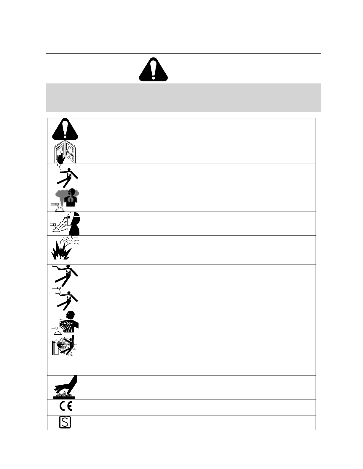
Safety
WARNING
This equipment must be used by qualified personnel. Be sure that all installation, operation, maintenance and repair
procedures are performed only by qualified individuals. Read and understand this ma nual before operating this equipment.
Failure to follow the instructions in this manual could cause serious personal injury, loss of life, or damage to this
equipment. Read and understand the following explanations of the warning symbols. Lincoln Electric is not responsible for
damages caused by improper installation, improper care or abnormal operation.
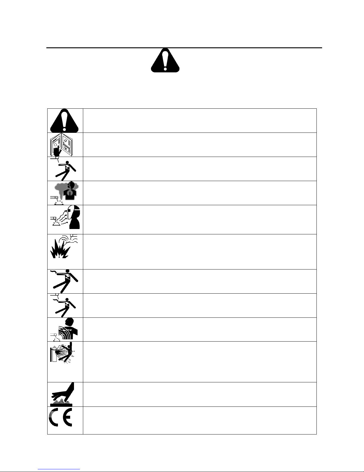
WARNING: This symbol indicates that instructions must be followed to avoid serious personal injury,
loss of life, or damage to this equipment. Protect yourself and others from possible serious injury or
death.
READ AND UNDERSTAND INSTRUCTIONS: Read and understand this manual before operating
this equipment. Arc welding can be hazardous. Failure to follow the instructions in this manual could
cause serious personal injury, loss of life, or damage to this equipment.
ELECTRIC SHOCK CAN KILL: Welding equipment generates high voltages. Do not touch the
electrode, work clamp, or connected work pieces when this equipment is on. Insulate yourself from
the electrode, work clamp, and connected work pieces.
FUMES AND GASES CAN BE DANGEROUS: Welding may produce fumes and gases hazardous to
health. Avoid breathing these fumes and gases. To avoid these dangers the operator must use
enough ventilation or exhaust to keep fumes and gases away from the breathing zone.
ARC RAYS CAN BURN: Use a shield with the proper filter and cover plates to protect your eyes from
sparks and the rays of the arc when welding or observing. Use suitable clothing made from durable
flame-resistant material to protect you skin and that of your helpers. Protect other nearby personnel
with suitable, non-flammable screening and warn them not to watch the arc nor expose themselves to
the arc.
WELDING SPARKS CAN CAUSE FIRE OR EXPLOSION: Remove fire hazards from the welding
area and have a fire extinguisher readily available. Welding sparks and hot materials from the welding
process can easily go through small cracks and openings to adjacent areas. Do not weld on any
tanks, drums, containers, or material until the proper steps have been taken to insure that no
flammable or toxic vapors will be present. Never operate this equipment when flammable gases,
vapors or liquid combustibles are present.
ELECTRICALLY POWERED EQUIPMENT: Turn off input power using the disconnect switch at the
fuse box before working on this equipment. Ground this equipment in accordance with local electrical
regulations.
ELECTRICALLY POWERED EQUIPMENT: Regularly inspect the input, electrode, and work clamp
cables. If any insulation damage exists replace the cable immediately. Do not place the electrode
holder directly on the welding table or any other surface in contact with the work clamp to avoid the
risk of accidental arc ignition.
ELECTRIC AND MAGNETIC FIELDS MAY BE DANGEROUS: Electric current flowing through any
conductor creates electric and magnetic fields (EMF). EMF fields may interfere with some
pacemakers, and welders having a pacemaker should consult their physician before oper ating this
equipment.
CYLINDER MAY EXPLODE IF DAMAGED: Use only compressed gas cylinders containing the
correct shielding gas for the process used and properly operating regulators designed for the gas and
pressure used. Always keep cylinders in an upright position securely chained to a fixed support. Do
not move or transport gas cylinders with the protection cap removed. Do not allow the electrode,
electrode holder, work clamp or any other electrically live part to touch a gas cylinder. Gas cylinders
must be located away from areas where they may be subjected to physical damage or the welding
process including sparks and heat sources.
WELDED MATERIALS CAN BURN: Welding generates a large amount of heat. Hot surfaces and
materials in work area can cause serious burns. Use gloves and pliers when touching or moving
materials in the work area.
CE COMPLIANCE: This equipment complies to the Central European directives.

5
SAFETY MARK: This equipment is suitable for supplying power for welding operations carried out in
an environment with increased hazard of electric shock.
Installation and Operator Instructions
Read this entire section before installation or operation
of the machine.
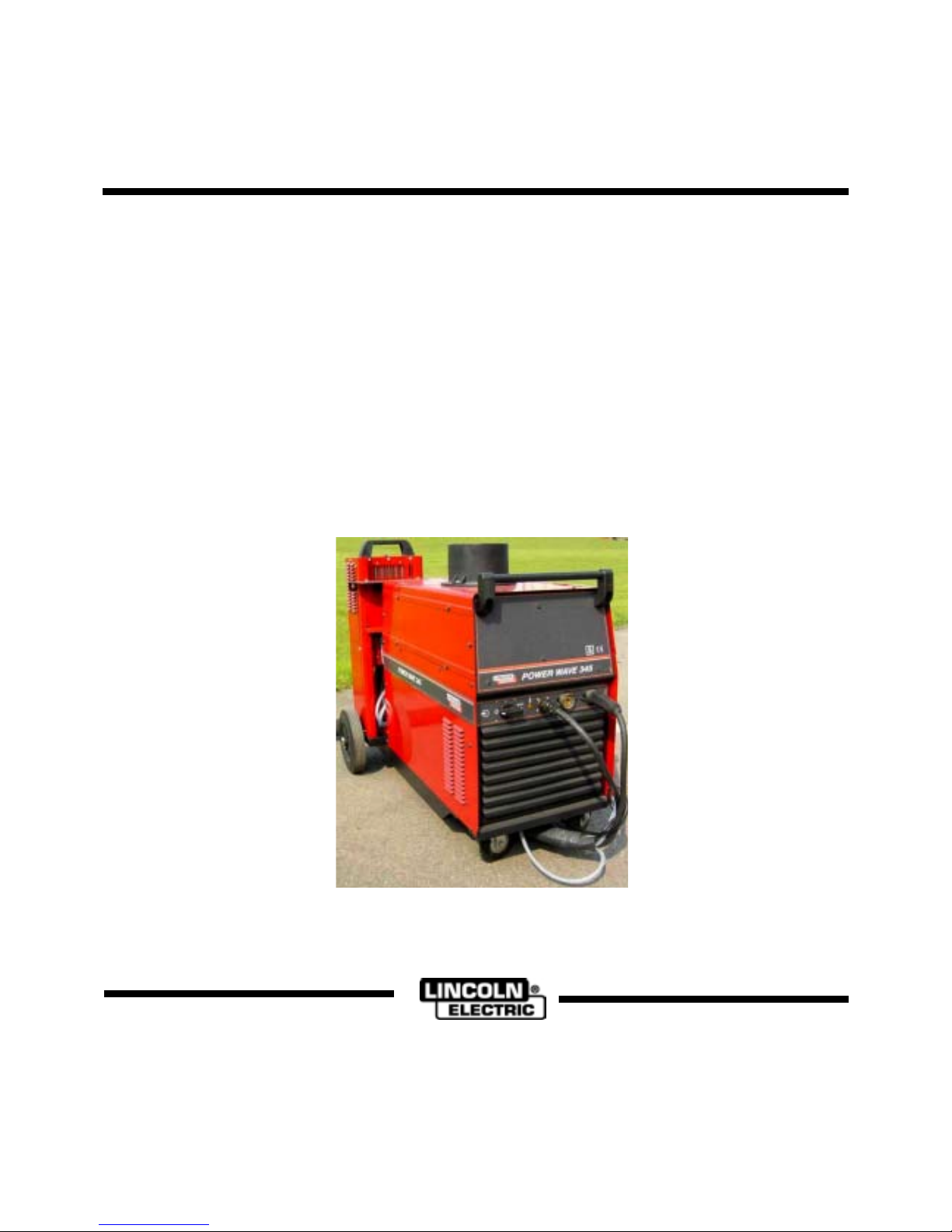
Product Description
The PW345 is a semiautomatic multi-process DC arc
welding machine offering CV and CC DC welding. It is
rated for 350Amps at 35% and 300 amps at 60% duty
cycle. Equipped with the correct wire feeder (LF40 code
54000 and above), this machine is able to weld CCStick, CC-GTAW, CV-FCAW, synergic and non-synergic
CV-GMAW / synergic GMAW-P processes. The digital
microcomputer based control system allows easy and
accurate adjustment of weld parameters through the
multi-process panel located on the wire feeder.
It is available with :
- 230 VAC/ 3.5 amp auxiliary power for water cooler.
For a quick and easy handling within the welding area, it
is factory mounted on a built-in undercarriage equipped
with a platform for a gas cylinder.
Location and Environment
This machine will operate in harsh environments.
However, it is important that simple preventative
measures are followed to assure long life and reliable
operation.
x Do not place or operate this machine on a surface
with an incline greater than 7° from horizontal.
x This machine must be located where there is free
circulation of clean air without restrictions for air
movement to and from the air vents. Do not cover
the machine with paper, cloth or rags when switched
on.
x Dirt and dust that can be drawn into the machine
should be kept to a minimum.
x This machine has a protection rating of IP23. It can
be used in moderate raining conditions without
causing any danger for users' safety..
x Locate the machine away from radio controlled
machinery. Normal operation may adversely affect
the operation of nearby radio controlled machinery,
which may result in injury or equipment damage.
Read the section on electromagnetic compatibility in
this manual.
x Do not operate in areas with an ambient
temperature greater than 40°C.
x This machine cannot be used for pipe thawing.
Input Supply Connection
Check the input voltage, phase, and frequency supplied
to this machine before turning it on. The allowable input
voltage is indicated in the technical specification section
of this manual and on the rating plate of the machine.
Verify the connection of grounding wires from the
machine to the input source.
The frame of this machine must be grounded. A ground
terminal located on the base of the generator is provided
for this purpose.
This machine is factory 3ph-400V connected. To connect
it in 3ph-230V, remove the left case panel of the
machine (A) to have access to the input reconnect
panel. Modify the connections according to the
connection diagram located on the inside of the case
side.
Gas Connection
Once a gas cylinder has been securely installed on the
machine, connect the gas hose of the input cable to the
gas cylinder using a flow regulator.
Output connections
Ground cable delivered with the machine has Twist-mate
plugs for connection to the POWER WAVE 345.
Use the shortest possible cable lengths.
When using an pulse type power source like
thePowerWaves, use the largest welding (electrode and
work) cables that are practical, even if the average
output current would not normally require it. When
pulsing, the pulse current can reach very high levels.
Voltage drops can become excessive, leading to poor
welding characteristics, if undersized welding cables are
used.
Changing Polarity
Connect the output lead to the desired polarity and the
ground lead to the other terminal.
The positive terminal marked (+) is the standard
configuration. This polarity is mainly used on GMAW and
FCAW-GS welding mode.
The negative terminal marked (-) is mainly used on
FCAW-SS ( Innershield) welding mode.
Negative electrode polarity :
When operating with electrode polarity negative the
"Electrode Sense Polarity" DIP switch must be set to the
"Negative" position on the Wire Drive Feed Head PC
Board. The default setting of the switch is positive
electrode polarity. Consult the Wire Drive instruction
manual for further details.
Cable sizes for combined lengths of
work cable
Machine
size
Lengths up to
45m
Lengths from
45 to 60m
300A @ 60%
or
350A @ à 35%
70 mm²
(Standard cable)
95 mm²
6
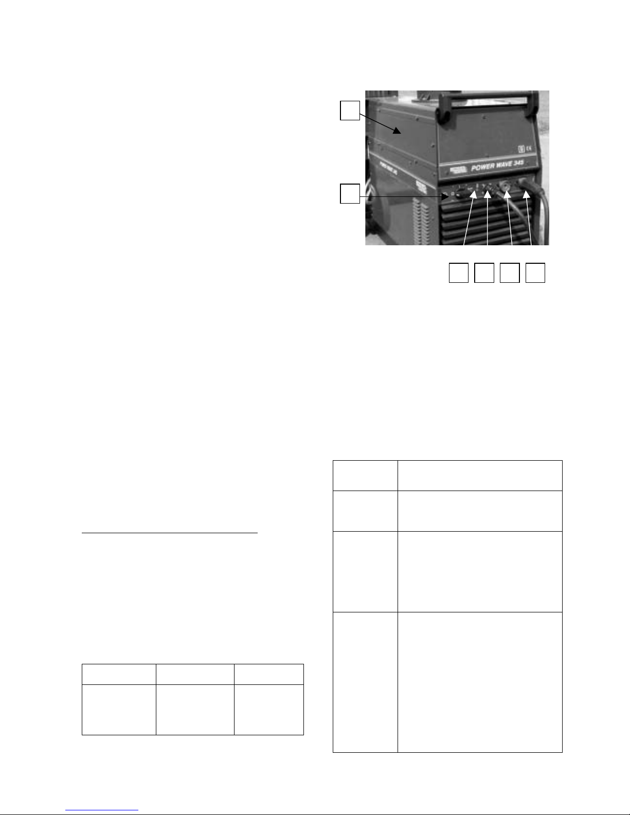
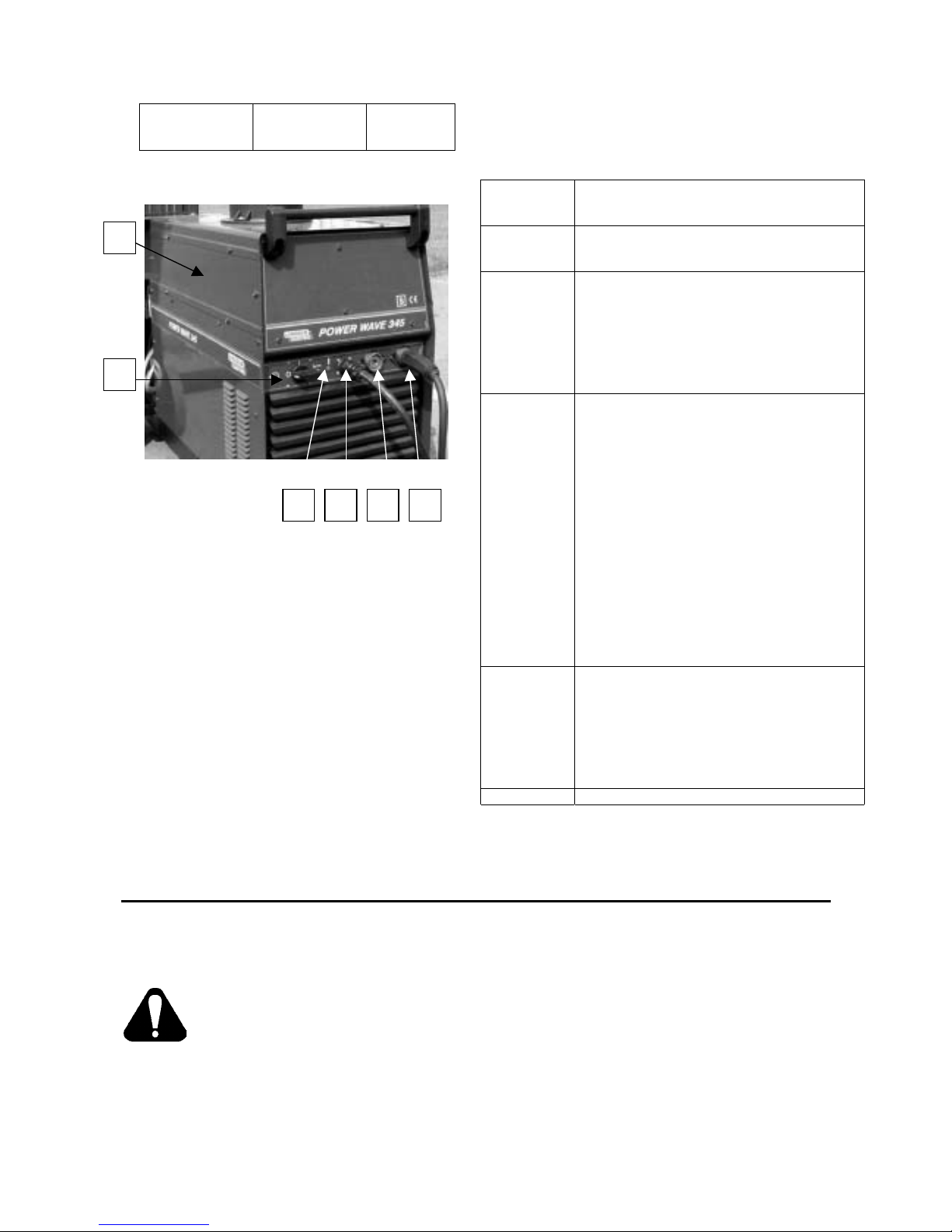
Controls on the case front
A. Left Case Panel
B. ON/OFF Switch
: It controls the input power to the
machine. Be sure the power source is connected to the
mains supply before turning power on ( "I").
C. Status light
A two color light that indicates system
errors. Normal operation is a steady green light. (see
Table B.1 below)
D. Wire Feeder Receptacle
(5-PIN)
E. Fast mate Adaptor Female (Negative polarity)
F. Fast mate Adaptor Female (Positive polarity)
NOTA
: The rating plate is located on the rear panel of
the machine.
TABLE B.1
Light
Condition
Meaning
Steady Green System OK. Power source
communicating normally
with wire feeder and its components
Blinking
Green
Occurs during a reset, and indicates the
POWER WAVE is mapping (identifying)
each component in the system. Normal
for first 1-10 seconds after power is
turned on, or if the system configuration
is changed
during operation
Alternating
Green and
Red
Non-recoverable system fault. If the PS
Status light is flashing any combination
of red and green, errors are present in
the POWER WAVE.
Read the error
code before the machine is turned
off.
Individual code digits are flashed in red
with a long pause between digits. If
more than one code is present, the
codes will be separated by a green
light.
To clear the error, turn power source
off, and back on to reset. See
Troubleshooting Section in the wire
feeder manual.
Steady Red Non recoverable hardware fault.
Generally indicates nothing is
connected to the POWER WAVE wire
feeder receptacle.
See Troubleshooting Section in the wire
feeder manual.
Blinking Red Not applicable.
Electromagnetic Compatibility (EMC)
This machine has been designed in accordance with all relative directives and norms. However, it may still generate
electromagnetic disturbances that can affect other systems like telecommunications (telephone, radio, and television) or
other safety systems. These disturbances can cause safety problems in the affected systems. Read and understand this
section to eliminate or reduce the amount of electromagnetic disturbance generated by this machine.
WARNING: This machine has been designed to operate in an industrial area. To operate in a domestic
area it is necessary to observe particular precautions to eliminate possible electromagnetic disturbances.
The operator must install and operate this equipment as described in this manual. If any electromagnetic
disturbances are detected the operator must put in place corrective actions to eliminate these disturbances
with, if necessary, assistance from Lincoln Electric France. Do not modify this machine without the written
approval of Lincoln Electric.
Before installing the machine, the operator must check the work area for any devices that may malfunction because of
electromagnetic disturbances. Consider the following.
x Input and output cables, control cables, and telephone cables that are in or adjacent to the work area and the
machine.
x Radio and/or television transmitters and receivers.
x Computers or computer controlled equipment.
x Safety and control equipment for industrial processes.
x Personal medical devices like pacemakers and hearing aids.
x Equipment for calibration and measurement.
x Check the electromagnetic immunity for equipment operating in or near the work area. The operator must be sure that
all equipment in the area is compatible. This may require additional protection measures.
x The dimensions of the work area to consider will depend on the construction of the area and other activities that are
taking place.
Consider the following guidelines to reduce electromagnetic emissions from the machine.
A
E
FBD
C
7
x Connect the machine to the input supply according to this manual. If disturbances occur if may be necessary to take
additional precautions such as filtering the input supply.
x The output cables should be kept as short as possible and should be positioned together.
x If possible connect the work piece to ground in order to reduce the electromagnetic emissions. The operator must
check that connecting the work piece to ground does not cause problems or unsafe operating conditions for personnel
and equipment.
x Shielding of cables in the work area can reduce electromagnetic emissions. This may be necessary for special
applications.
POWER WAVE 345 Technical Specifications
INPUT
Input Voltage
230 / 400 V
3 phase
Frequency
50 Hertz (Hz)
RATED OUTPUT
Duty Cycle (acc. EN60974-1)
(Based on a 10 min. period)
35%
60%
100%
Output Current
350 A
300 A
230 A
OUTPUT RANGE
Welding Current Range
5 – 350 Amps
Auxiliary Power
230V AC (water cooler)
DIMENSIONS
Heigth (mm)
880
Width (mm)
680
Length ( mm)
1100
Weight ( Kg)
135 (air)
162 (water)
Operating Temperature
–20°C to +40°C
Storage Temperature
-25°C to 55°C
For any maintenance or repair operations it is recommended to contact the nearest Lincoln technical service center.
Maintenance or repairs preformed by unauthorized service centers or personnel will null and void the manufacturers
warranty..

8
Sicurezza
02/02
AVVERTENZA
Questa macchina deve essere impiegata solo da personale qualificato. Assicuratev i che tutte le proc ed ure di installa z ion e,
impiego, manutenzione e riparazione vengano eseguite solamente da pers one qualific ate. Leggere e compre ndere qu esto
manuale prima di mettere in funzione la macchina. La mancata osservanza delle istruzioni di questo manuale può
provocare seri infortuni, anche mortali, alle persone, o danni alla macchina. Leggere e comprendere le spiegazioni
seguenti sui simboli di avvertenza. La Lincoln Electric Italia non si assume alcuna resp onsabilità per danni consegue nti a
installazione non corretta, incuria o impiego in modo anormale.
AVVERTENZA: Questo simbolo indica che occorre seguire le istruzioni per evitare seri infortuni,
anche mortali, alle persone o danni a questa macchina. Proteggete voi stessi e gli altri dalla
possibilità di seri infortuni anche mortali.
LEGGERE E COMPRENDERE LE ISTRUZIONI: Leggere e comprendere questo manuale prima di
far funzionare la macchina. La saldatura ad arco può presentare dei rischi. La mancata osservanz a
delle istruzioni di questo manuale può provocare seri infortuni, anche mortali, alle persone o danni alla
macchina.
LA FOLGORAZIONE ELETTRICA E’ MORTALE: Le macchine per saldatura generano tensioni
elevate. Non toccate l’elettrodo, il morsetto di massa o pezzi da saldare collegati alla macchina
quando la macchina è accesa. Mantenetevi isolati elettricamente da elettrodo, morsetto e pezzi
collegati a questo.
FUMI E GAS POSSONO ESSERE PERICOLOSI: La saldatura può produrre fumi e gas dannosi alla
salute. Evitate di respirare questi fumi e gas. Per evitare il pericolo l’operatore deve disporre di una
ventilazione o di un'estrazione di fumi e gas che li allontanino dalla zona in cui respira.
I RAGGI EMESSI DALL’ARCO BRUCIANO: Usate una maschera con schermatura adatta a
proteggervi gli occhi da spruzzi e raggi emessi dall’arco mentre saldate o osservate la saldatura.
Indossare indumenti adatti in materiale resistente alla fiamma per proteggere il corpo, sia vostro che
dei vostri aiutanti. Le persone che si trovano nelle vicinanze devono essere protette da schermature
adatte, non infiammabili, e devono essere avvertite di non guardare l’arco e di non es porvisi.
GLI SPRUZZI DI SALDATURA POSSONO PROVOCARE INCENDI O ESPLOSIONI: Allontanare
dall'area di saldatura quanto può prendere fuoco e tenere a portata di mano un estintore. Gli spruzzi
o altri materiali ad alta temperatura prodotti dalla saldatura attraversano con facilità eventuali piccole
aperture raggiungendo le zone vicine. Non saldare su serbatoi, bidoni, contenitori o altri materiali fino
a che non si sia fatto tutto il necessario per assicurarsi dell'assenza di vapori infiammabili o nocivi.
Non impiegare mai questa macchina se vi è presenza di gas e/o vapori infiammabili o com bustibili
liquidi.
MACCHINA CON ALIMENTAZIONE ELETTRICA: Togliere l’alimentazione con l’interruttore ai fusibili
prima di svolgere operazioni su questa macchina. Mettere la macchina a terra secondo le normative
vigenti.
MACCHINA CON ALIMENTAZIONE ELETTRICA: Ispezionare periodicamente i cavi di
alimentazione, all’elettrodo e al pezzo. Se si riscontrano danni all’isolamento sostituire
immediatamente il cavo. Non posare la pinza portaelettrodo direttamente sul banco di saldatura o
qualsiasi altra superficie in contatto con il morsetto di massa per evitare un innesco involontario
dell’arco.
I CAMPI ELETTRICI E MAGNETICI POSSONO ESSERE PERICOLOSI: Il passaggio di corrente
elettrica in un conduttore produce campi elettromagnetici. Questi campi possono interferire con alcuni
cardiostimolatori (“pacemaker”) e i saldatori con un cardiostimolatore devono consultare il lor o medico
su possibili rischi prima di impiegare questa macchina.
LE BOMBOLE POSSONO ESPLODERE SE SONO DANNEGGIATE: Impiegate solo bombole
contenenti il gas compresso adatto al processo di saldatura utilizzato e regolatori di flusso, funzionanti
regolarmente, progettati per il tipo di gas e la pressione in uso. Le bombole vanno tenute sempre in
posizione verticale e assicurate con catena ad un sostegno fisso. Non spostate le bombole senza il
loro cappello di protezione. Evitate qualsiasi contatto dell’elettrodo, della sua pinza, del morsetto di
massa o di ogni altra parte in tensione con la bombola del gas. Le bombole gas vanno collocate
lontane dalle zone dove possano restare danneggiate dal processo di saldatura con relativi spruzzi e
da fonti di calore.
I MATERIALI SALDATI BRUCIANO: Il processo di saldatura produce moltissimo calore. Ci si può
bruciare in modo grave con le superfici e materiali caldi della zona di saldatura. Impiegare guanti e
pinze per toccare o muovere materiali nella zona di saldatura.

9
CONFORMITÀ CE: Questa macchina è conforme alle Direttive Europee.
MARCHIO DI SICUREZZA: Questa macchina è adatta a fornire energia per operazioni di saldatura
svolte in ambienti con alto rischio di folgorazione elettrica.
Installazione e istruzioni operative
Leggere tutta questa sezione prima di installare o
impiegare la macchina
Descrizione
Il PW345 è una saldatrice ad arco multiprocesso che
permette di saldare in corrente continua a tensione
costante (CV) o corrente costante (CC). Fornisce 350 A
nominali con fattore di intermittenza 35% e 300 A con il
60%. Una volta munita del trainafilo adatto (LF40 di
codice 54000 e superiore) la macchina può saldare con
procedimenti CC elettrodo manuale, CC GTAW, CV
FCAW, CV GMAW sinergici e non, GMAW P sinergici.
Il sistema di controllo con microprocessore digitale
consente una regolazione facile ed accurata dei
parametri di saldatura mediante il pannello multi
processo disposto sul trainafilo.
E’ disponibile con:
Uscita ausiliaria in c.a., 230 V/3,5 A per gruppo
raffreddamento acqua
Per facilitarne la rapidità di manovra nell’area di
saldatura viene montata in fabbrica su un carrello
incorporato munito di piattaforma per la bombola gas.
Collocazione e ambiente
Questa macchina è in grado di funzionare in ambienti
difficili. E’ comunque importante seguire delle semplici
misure di prevenzione per garantirne una lunga durata e
un funzionamento affidabile.
x Non collocare o impiegare la macchina su superfici
inclinate più di 7° rispetto all’orizzontale.
x La macchina va collocata ove vi sia una circolazione
di aria pulita senza impedimenti al suo movimento in
entrata e uscita dalle feritoie. Non coprire la
macchina con fogli di carta, panni o stracci quando
è accesa.
x Tenere al minimo polvere e sporco che possano
entrare nella macchina.
x Questa macchina ha Grado di Protezione IP 23.
Può quindi essere utilizzata in condizioni di pio ggia
moderata senza causare alcun rischio per la
sicurezza degli utilizzatori.
x Disponete la macchina lontana da macchinari
controllati via radio. Il suo funzionamento normale
può interferire negativamente sul funzionamento di
macchine controllate via radio poste nelle vicinanze,
con conseguenze di infortuni o danni materiali.
Leggete la sezione sulla compatibilità
elettromagnetica di questo manuale.
x Non impiegate la macchina in zone ove la
temperatura ambiente supera i 40°C.
x La macchina non può essere utilizzata per
scongelare i tubi.
10
Collegamento all’alimentazione
Prima di accendere la macchina verificare tensione, fasi
e frequenza dell’alimentazione.
La tensione impiegabile è indicata nelle “Specifiche
Tecniche” di questo manuale e sulla targhetta della
macchina.
Verificate il collegamento di terra fra macchina e
alimentazione.
Il telaio della macchina va messo a terra; a questo scopo
sulla sua base si trova un terminale apposito.
In fabbrica la macchina viene predisposta per
alimentazione trifase a 400 V. Per portarla su 230 trifase
togliere il pannello sulla sinistra dell’involucro (A) per
accedere al quadro cambio tensioni.
Modificare i collegamenti seguendo lo schema disposto
all’interno della fiancata.
Collegamento del gas
Installare una bombola sulla macchina assicurandovela
bene, poi collegare alla bombola il tubo gas del cavo di
ingresso interponendo un regolatore di flusso.
Collegamenti in uscita
Il cavo massa fornito con la macchina è munito di
connettore Twist-Mate per collegarlo al POWER WAVE
345. Impiegate il cavo più corto possibile.
Con un generatore pulsato come il Power Wave, si
devono usare i più grossi cavi corrente e massa
impiegabili, superiori a quelli necessari per il valore
medio della corrente in uscita. La corrente pulsata può
raggiungere valori molto alti in pulsazione; si possono
avere cadute di tensione eccessive che provocano
caratteristiche di saldatura insufficienti, se i cavi di
saldatura sono sottodimensionati.
Cambio della polarità
Collegare il cavo corrente al terminale della polarità
richiesta e il cavo massa all’altro terminale.
La configurazione standard è quella al terminale positivo
marcato (+) e viene di solito usata saldando in GMAW e
FCAW-GS.
Il terminale negativo, marcato (-), è in genere usato per
saldatura in FCAW-SS (Innershield).
Funzionamento con elettrodo al polo negativo:
Saldando con elettrodo al polo negativo il
microinterruttore “Sensore polarità elettrodo” della
scheda elettronica del trainafilo va posto su “Negativo”.
La posizione standard del microinterruttore è invece su
polarità positiva.
Troverete altri dettagli sul manuale di istruzioni del
trainafilo.
Sezione dei cavi in funzione della
lunghezza totale dei cavi massa.
Funzionamento Lunghezza fino a
45 m
Lunghezza da
45 a 60 m
300A @ 60%
oppure
350A @ à 35%
70 mm²
(Cavo Standard )
95 mm²
Comandi sul frontale macchina
A.
Pannello
sinistro
B.
Interruttore generale
. Comanda l’alimentazione
alla macchina . Prima di accendere portando
l’interruttore su “I”, accertarsi che la macchina sia
collegata alla rete
C.
Luce di stato
. Indicatore luminoso bicolore che
segnala eventuali errori del sistema.
Luce verde fissa indica funzionamento normale
(vedere Tabella B.1)
D.
Presa per trainafilo
(5 pin)
E. Attacco Fast-Mate femmina (polarità negativa)
F. Attacco Fast-Mate femmina (polarità positiva)
NOTA : La targhetta dati macchina si trova sul pannello
posteriore.
Tabella n. 1
SITUAZIONE
LUCE
SIGNIFICATO
Verde fisso Sistema OK. Il generatore comunica
normalmente con il trainafilo e i suoi
componenti
Lampeggia
verde
Riarmo in corso, indica che il POWER
WAVE sta identificando tutti i
componenti del sistema. Avviene
normalmente per i primi 10 secondi dopo
l’accensione o dopo variazioni della
configurazione del sistema in corso di
funzionamento
Lampeggia
verde e rosso
alternati
Errore di sistema non ricuperabile. Per
qualsiasi combinazione di rosso e verde
lampeggiante sulla luce di stato del
generatore, il problema è nel POWER
WAVE. Leggere il codice di errore prima
di spegnere la macchina.
Il manuale di servizio dà l’interpretazione
del Codice Errore indicato dalla luce di
stato. Le singole cifre del codice
vengono indicate da lampi rossi
intervallati da pause lunghe. Un lampo
verde separa i codici se sono più di uno.
Per eliminare l’errore spegnere il
A
E
FBD
C
11
generatore e accenderlo per riarmare.
Vedere Sezione Ricerca Guasti nel
manuale del trainafilo
Rosso fisso Errore non recuperabile nel hardware. Di
solito indica che alla presa per trainafilo
sul POWER WAVE non è attaccato
niente. Vedere Sezione Ricerca Guasti
nel manuale del trainafilo
Lampeggia
rosso
Non applicabile.
Compatibilità Elettromagnetica (EMC)
Questa macchina è stata progettata nel rispetto di tutte le direttive e normative in materia.
Tuttavia può generare dei disturbi elettromagnetici che possono interferire con altri sistemi come le
telecomunicazioni (telefono, radio o televisione) o altri sistemi di sicurezza. I disturbi possono provocare
problemi nella sicurezza dei sistemi interessati. Leggete e comprendete questa sezione per eliminare o ridurre
il livello dei disturbi elettromagnetici generati da questa macchina.
La macchina è stata progettata per funzionare in ambienti di tipo industriale. Il suo impiego in
ambienti domestici richiede particolari precauzioni per l’eliminazione dei po ssibili disturbi
elettromagnetici. L’operatore deve installare e impiegare la macchina come precisato in questo
manuale. Se si riscontrano disturbi elettromagnetici l’operatore deve porre in atto azioni correttive
per eliminarli, avvalendosi, se necessario, dell’assistenza della Lincoln Electric.
Prima di installare la macchina, controllate se nell’area di lavoro vi sono dispositivi il cui funzionamento
potrebbe risultare difettoso a causa di disturbi elettromagnetici. Prendete in considerazione i seguenti:
x Cavi di entrata o di uscita, cavi di controllo e cavi telefonici collocati nell’area di lavoro, presso la macchina
o nelle adiacenze di questa.
x Trasmettitori e/o ricevitori radio o televisivi. Computers o attrezzature controllate da computer.
x Impianti di sicurezza e controllo per processi industriali. Attrezzature di taratura e misurazione.
x Dispositivi medici individuali come cardiostimolatori (pacemakers) o apparecchi acustici.
x Verificare che macchine e attrezzature funzionanti nell’area di lavoro o nelle vicinanze siano immuni da
possibili disturbi elettromagnetici. L’operatore deve accertare che tutte le attrezzature e dispositivi
nell’area siano compatibili. A questo scopo può essere necessario disporre misure di protezione
aggiuntive.
x L’ampiezza dell’area di lavoro da prendere in considerazione dipende dalla struttura dell’area e dalle altre
attività che vi si svolgono.
Per ridurre le emissioni elettromagnetiche della macchina tenete presenti le seguenti linee guida.
x Collegare la macchina alla fonte di alimentazione come indicato da questo manuale. Se vi sono disturbi,
può essere necessario prendere altre precauzioni, come un filtro sull’alimentazione.
x I cavi in uscita vanno tenuti più corti possibile e l’uno accanto all’altro. Se possibile mettere a terra il pezzo
per ridurre le emissioni elettromagnetiche. L’operatore deve controllare che questa messa a terra non
provochi problemi o pericoli alla sicurezza del personale e della macchina e attrezzature.
x Si possono ridurre le emissioni elettromagnetiche schermando i cavi nell’area di lavoro.
Per impieghi particolari questo può diventare necessario.
Power Wave 345 Specifiche Tecniche
ALIMENTAZIONE
Tensione di alimentazione
230 / 400 V
trifase
Frequenza
50 Hertz (Hz)
USCITA NOMINALE
Fattore di intermittenza (EN60974-1)
(su periodo di 10 minuti)
35%
60%
100%
Corrente in uscita
350 A
300 A
230 A
USCITA

12
Gamma corrente di saldatura
5 – 350 A
Alimentazione Ausiliaria
230V AC (gruppo raffreddamento)
DIMENSIONI
Altezza (mm)
880
Larghezza (mm)
680
Lunghezza (mm)
1100
Peso (Kg)
135 (aria)
162 (acqua)
Temperatura di impiego
–20°C a +40°C
Temperatura di immagazzinamento
-25°C a 55°C
Per ogni operazione di manutenzione o riparazione si raccomanda di rivolgersi al più vicino centro di
assistenza tecnica della Lincoln Electric Italia. Manutenzioni o riparazioni effettuate da personale o centri di
servizio non autorizzati fanno decadere la garanzia del fabbricant
13
Sicherheitsmaßnahmen / Unfallschutz
06/02
ACHTUNG
Diese Anlage darf nur von ausgebildeten Leuten benutzt, gewartet und repariert werden. Schließen Sie dieses Gerät nicht
an, arbeiten Sie nicht damit oder reparieren Sie es nicht, bevor Sie diese Betriebsanleitung gelesen und verstanden haben.
Bei Nichtbeachtung der Hinweise kann es zu gefährlichen Verletzungen bis hin zum Tod oder zu Beschädigun gen am
Gerät kommen. Beachten Sie auch die folgenden Beschreibungen der Warnhinweise. Lincoln Electric ist nicht
verantwortlich für Fehler, die durch inkorrekte Installation, mangelnde Sorgfalt oder Fehlbenutzung des Gerätes entstehen.
ACHTUNG: Dieses Symbol gibt an, dass die folgenden Hinweise beachtet werden müssen, um
gefährliche Verletzungen bis hin zum Tode oder Beschädigungen am Gerät zu verhindern. Schützen
Sie sich und andere vor gefährlichen Verletzungen oder dem Tode.
BEACHTEN SIE DIE ANLEITUNG: Lesen Sie diese Anleitung sorgfältig, bevor Sie das Gerät in
Betrieb nehmen. Bei Nichtbeachtung der Hinweise kann es zu gefährlichen Verletzu ngen bis hin zum
Tod oder zu Beschädigungen am Gerät kommen.
STROMSCHLÄGE KÖNNEN TÖDLICH SEIN: Schweißgeräte erzeugen hohe Stromstärken.
Berühren Sie keine stromführenden Teile oder die Elektrode mit der Haut oder nasser Kleidung.
Schützen Sie beim Schweißen Ihren Körper durch geeignete isolierende Kleidung und Ha ndschuhe.
RAUCH UND GASE KÖNNEN GEFÄHRLICH SEIN: Schweißen erzeugt Rauch und Gase, die
gesundheitsschädlich sein können. Vermeiden Sie das Einatmen dieser Metalldämpfe. Benutzen Sie
eine Schweißrauchabsaugung, um die Dämpfe abzusaugen.
LICHTBÖGEN KÖNNEN VERBRENNUNGEN HERVORRUFEN: Tragen Sie geeignete Schutzkleidungen und Schutzmasken für Augen, Ohren und Körper, um sich vor Spritzern und Strahlungen
zu schützen. Warnen Sie auch in der Umgebung befindliche Personen vor den Gefahren des
Lichtbogens. Lassen Sie keinen ungeschützt den Lichtbogen beobachten.
SCHWEISSPRITZER KÖNNEN FEUER ODER EXPLOSIONEN VERURSACHEN: Entfernen Sie
feuergefährliche Gegenstände vom Schweißplatz und halten Sie einen Feuerlöscher bereit.
Schweißen Sie keine Behälter, die brennbare oder giftige Stoffe enthalten, bis diese vollständig
geleert und gesäubert sind. Schweißen Sie niemals an Orten, an denen brennbare Gase, Stoffe oder
Flüssigkeiten vorhanden sind.
ELEKTRISCHE GERÄTE: Schalten Sie die Netzspannung am Sicherungskasten aus oder ziehen Sie
den Netzstecker, bevor Arbeiten an der Maschine ausgeführt werden. Erden Sie die Maschine
gemäß den geltenden elektrischen Bestimmungen.
ELEKTRISCHE GERÄTE: Achten Sie regelmäßig darauf, dass Netz-, Werkstück- und Elektrodenkabel in einwandfreiem Zustand sind und tauschen Sie diese bei Beschädigung a us. Lege n Sie
den Elektrodenhalter niemals auf den Schweißarbeitsplatz, damit es zu keinem ungewollten
Lichtbogen kommt.
ELEKTRISCHE UND MAGNETISCHE FELDER BERGEN GEFAHREN: Elektrischer Strom, der
durch ein Kabel fließt erzeugt, ein elektrisches und magnetisches Feld (EMF). EMF Felder können
Herzschrittmacher beeinflussen. Bitte fragen Sie Ihren Arzt, wenn Sie einen Herzschrittmacher
haben, bevor Sie dieses Gerät benutzen.
DEFEKTE GASFLASCHEN KÖNNEN EXPLODIEREN: Benutzen Sie nur Gasflaschen mit dem für
den Schweißprozess geeigneten Gas und ordnungsgemäßen Druckreglern, die für dieses Gas
ausgelegt sind. Lagern Sie Gasflaschen aufrecht und gegen Umfallen gesichert. Bewegen Sie keine
Gasflasche ohne Ihre Sicherheitskappe. Berühren Sie niemals eine Gasflasche mit der Elektrode,
Elektrodenhalter, Massekabel oder einem anderen stromführenden Teil. Gasflaschen dürfen nicht an
Plätzen aufgestellt werden, an denen sie beschädigt werden können, inklusive Schweißspritzern und
Wärmequellen.
GESCHWEISSTE MATERIALIEN KÖNNEN VERBRENNUNGEN VERURSACHEN: Schweißen verursacht hohe Temperaturen. Heiße Materialien können somit ernsthafte Verbrennungen verursachen.
Benutzen Sie Handschuhe und Zangen, wenn Sie geschweißte Materialien berühren oder bewegen.
CE Konformität: Dieses Gerät erfüllt die CE-Normen.
S-ZEICHEN: Dieses Gerät darf Schweißstrom in Umgebungen mit erhöhter elektrischer Gefährdung
liefern.

14
Installation und Bedienungshinweise
Lesen Sie bitte diesen Abschnitt, bevor Sie das
Gerät installieren oder benutzen.
Produktbeschreibung
Die PW345 ist eine digitale Multiprozess-DCSchweißstromquelle. Der maximale Ausgangsstrom
beträgt 350 A bei 35% ED (300 A bei 60% ED).
Durch Ausstattung mit dem geeigneten
Drahtvorschubgerät (LF40 Code-Nr. 54000 und
darüber), ist die Maschine für die folgenden
Verfahren einsetzbar: E-Hand, WIG, MIG/MAGFülldraht, MIG/MAG-Synergic, MIG/MAG-NonSynergic und MIG/MAG-Impuls-Synergic. Über das
Bedienpanel auf der Front des
Drahtvorschubgerätes lassen sich die über einen
digitalen Mikroprozessor gesteuerten
Schweißparameter präzise und komfortabel auf die
gewünschten Werte einstellen. Die PW345 ist mit
einer 230 V / 3,5A-Steckdose für das
Wasserkühlgerät erhältlich.
Zur einfachen Beweglichkeit der Maschine innerhalb
ihres Einsatzfeldes wird jede Anlage mit einem
werksseitig montierten Fahrgestell und einer
Gasflaschenplattform ausgeliefert.
Standort und Umgebung
Diese Maschine ist für den Einsatz in rauer Umgebung ausgelegt. Dennoch sollten die folgenden
Punkte für eine lange Lebensdauer beachtet werden:
x Stellen Sie das Gerät nicht auf Ebenen mit
mehr als 7° horizontaler Neigung.
x Die Maschine muss an einem Ort installiert
werden, an dem eine freie und saubere
Luftzirkulation gewährleistet ist. Bedecken Sie
die Maschine nicht mit Papier, Stoff oder Plane,
wenn sie eingeschaltet ist.
x Staub, der in die Maschine gelangen kann,
sollte auf ein Minimum reduziert werden.
x Dieses Gerät ist nach IP23 geschützt und kann
entsprechend dieser Schutzklasse auch bei
leichtem Regen gefahrlos im Freien betrieben
werden.
x Halten Sie die Maschine von elektronischen
Anlagen fern. Normaler Betrieb kann zu Störungen dieser Anlagen führen. Lesen Sie hierzu
auch das Kapitel "Elektromagnetische Verträglichkeit".
x Betreiben Sie die Maschine nicht bei Tempera-
turen über 40°C.
x Die Stromquelle ist nicht geeignet, um
eingefrohrene Rohrleitungen durch
Widerstandserwärmung aufzutauen.
Anschluss an das Stromnetz
Prüfen Sie die Netzeingangsspannung sowie
Phasen und Frequenz der Netzversorgung, bevor
Sie die Maschine in Betrieb nehmen. Die erlaubte
Eingangsspannung entnehmen Sie dieser Anleitung
oder dem Typenschild der Maschine. Prüfen Sie
die Erdverbindung der Maschine zum Netzeingang.
Der Rahmen und das Gehäuse dieser Stromquelle
müssen geerdet sein. Einen für diesen Zweck
vorgesehenen Anschluss finden Sie auf der
Bodenplatte der PW345.
Diese Maschine ist werksseitig für den Betrieb an
3ph-400V voreingestellt worden. Für den Betrieb an
3ph-230V entfernen Sie die linke Seitenwand (A),
um an das Klemmbrett der Eingangsanschlüsse zu
gelangen. Verändern Sie dann entsprechend dem
Anschlussplan auf der Innenseite des
Gehäusedeckels die Anschlussbelegungen.
Gasanschluss
Nach der sicheren Befestigung der Gasflasche auf
der hierzu vorgesehenen Plattform, verbinden Sie
den Schutzgasschlauch mit dem Druckminderer an
der Gasflasche.
Stromausgangsbuchsen
Das mit der Maschine ausgelieferte Massekabel ist
zum Anschluss an die POWER WAVE 345 mit einer
Dinse-Schnellkupplung ausgestattet worden.
Verwenden Sie stets so geringe Kabellängen wie
möglich.
Wenn Sie eine Impuls-Schweißmaschine einsetzen,
sollten die gewählten Querschnittsflächen von
Schweiß- und Massekabel so groß wie möglich
sein, auch wenn der durchschnittlich zu erwartende
Schweißstrom diese Kabelquerschnitte eigentlich
nicht erfordern würde. Zur einwandfreien
Übertragung der teilweise sehr hohen
Impulsstromspitzen sind überdimensionierte
Kabelquerschnitte unbedingt erforderlich, da es
ansonsten zu starken Spannungseinbrüchen
kommen kann, welche das Schweißverhalten und
das Ergebnis deutlich verschlechtern.
Wechsel der Elektrodenpolarität
Schließen Sie das Schweißkabel an den
gewünschten Pol an, und verbinden Sie
entsprechend das Massekabel mit dem anderen
Pol. Der Anschluss des Schweißkabels an die mit
(+) gekennzeichnete Ausgangsbuchse entspricht
der für die üblichen MIG/MAG-Prozesse am
häufigsten vorgeschriebenen Elektrodenpolung.
Eine negative Polung (-) der Elektrode wird
dagegen in der Regel beim Schweißen mit
selbstschützenden Fülldrähten eingesetzt
(Innershield).
Zur Beachtung bei negativer Elektrodenpolung:
Beim Schweißen mit negativer Elektrodenpolung
muss der Electrode-Sense-Polarity-DIP-Schalter,
der sich auf dem Wire-Drive-Feed-Head PC-Board
befindet, auf die Position "negative" umgeschaltet
werden. Im Auslieferungszustand des
Drahtvorschubgerätes befindet sich dieser DIPSchalter in der Stellung "positive". Weitere Details
hierzu entnehmen Sie bitte der
Bedienungsanleitung des Drahtvorschubgerätes.
Erforderliche Mindestquerschnitte
des Massekabels
Ausgangsstromstärke
Länge bis 45m Länge ab
45m bis 60m
70 mm² 95 mm²
15
A
E F
B
DC
300A @ 60% ED
oder
350A @ 35% ED
(Standard)
Bedienungs- und
Anschlusselemente:
A. linke Blechabdeckung
B. EIN/AUS Schalter
: Schaltet die
Netzeingangsspannung der Maschine ein und aus.
Vergewissern Sie sich, dass die Maschine
ordnungsgemäß an das Stromnetz angeschlossen
wurde, bevor Sie sie einschalten ( "I").
C. Kontrollleuchte:
Zweifarbige Kontrollleuchte zur
Anzeige von Systemfehlern. Im normalen
Betriebszustand leuchtet diese Lampe grün. (siehe
auch Tabelle B.1 unten)
D. Anschlussbuchse für das
Drahtvorschubgerät
(5-polig)
E. Dinse-Schnellkupplung (negativer Pol)
F. Dinse-Schnellkupplung (positiver Pol)
Hinweis
: Das Typenschild mit Angabe der
technischen Daten befindet sich auf der Rückseite
der Maschine.
Tabelle B.1
Zustand der
Kontroll-
leuchte
Bedeutung
dauerhaft
grün
leuchtend
System O.K. Stromquelle kommuniziert über
eine fehlerfreie Verbindung mit dem
Drahtvorschubgerät und dessen Komponenten.
grün blinkend Erscheint während eines System Resets und
signalisiert, dass die Stromquelle alle
Systemkomponenten abtastet und identifiziert.
Dieser Vorgang läuft automatisch innerhalb der
ersten 1-10 Sekunden nach jedem Einschalten
der POWER WAVE sowie bei jeder Änderung
der Konfiguration im eingeschalteten Zustand
automatisch ab.
im Wechsel
grün und rot
blinkend
Verschiedene Signalcodes mit
unterschiedlichen Blinksequenzen weisen
darauf hin, dass in der POWER WAVE ein
Systemfehler vorliegt.
Lesen und notieren Sie
den Fehlercode, bevor Sie die Maschine
wieder ausschalten!
Die einzelnen Ziffern des Fehlercodes werden
durch rote Blinksequenzen, die durch deutliche
Pausen getrennt sind, angezeigt. Wenn
mehrere Fehlermeldungen vorliegen, wird die
Anzeige der Fehlercodes durch grünes
Aufleuchten getrennt.
Zum Reset der Fehlermeldung schalten Sie die
Stromquelle zunächst aus und anschließend
wieder ein. Lesen Sie hierzu außerdem den
Abschnitt "Trouble Shooting" in der
Bedienungsanleitung des Drahtvorschubgerätes.
dauerhaft
rot
leuchtend
Eine dauerhaft rot leuchtende Kontrolllampe
weist auf einen Hardwarefehler des Systems
hin. In der Regel tritt dies bei nicht vorhandener
oder fehlerhafter Kabelverbindung zwischen
Stromquelle und Drahtvorschubgerät auf.
Lesen Sie hierzu außerdem den Abschnitt
"Trouble Shooting" in der Bedienungsanleitung
des Drahtvorschubgerätes.
rot blinkend keine Angabe
Elektromagnetische Verträglichkeit (EMC)
08/02
Diese Maschine wurde unter Beachtung aller zugehörigen Normen und Vorschriften geb aut. Dennoch kann es unter
besonderen Umständen zu elektromagnetischen Störungen anderer elektronischer Syteme (z.B. Telefon, Radio, TV,
Computer usw. ) kommen. Diese Störungen können im Extremfall zu Sicherheitsproblemen der beeinflussten Systeme
führen. Lesen Sie deshalb diesen Abschnitt aufmerksam durch, um das Auftreten elektromagnetischer Störungen zu
reduzieren oder ganz zu vermeiden.
Diese Maschine ist für den industriellen Einsatz konzipiert worden. Bei Benutzung dieser Anlage in Wohngebieten sind daher besondere Vorkehrungen zu treffen, um Störungen durch elektromagnetische
Beeinflussungen zu vermeiden. Halten Sie sich stets genau an die in dieser Bedienungsa nle itung genannten
Einsatzvorschriften. Falls dennoch elektromagnetische Störungen auftreten, müssen geeignete Gegenmaßnahmen
getroffen werden. Kontaktieren Sie gegebenenfalls den Kundendienst der Lincoln Smitweld GmbH. Technische
Änderungen der Anlage sind nur nach schriftlicher Genehmigung des Herstellers zul ässig.
Vergewissern Sie sich vor der Inbetriebnahme des Schweißgerätes, dass sich keine für elektromagnetische Störungen
 Loading...