

Page 1

®
RETURN TO MAIN MENU
POWER WAVE AC/DC 1000
IM848-A
June, 2009
For use with machines having Code Numbers:
Safety Depends on You
Lincoln arc welding and cutting
equipment is designed and built
with safety in mind. However, your
overall safety can be increased by
proper installation ... and thoughtful operat io n on your part. DO
NOT IN ST ALL, OPERAT E OR
REP A I R THIS EQU I P MENT
WIT H O UT REA D I NG THI S
MAN U A L A N D THE SAFET Y
PRE CAUT IONS CON TAIN ED
THR O U GHOUT . And , mos t
importantly, think before you act
and be careful.
11124, 11226
Cleveland, Ohio 44117-1199 U.S.A. TEL: 216.481.8100 FAX: 216.486.1751 WEB SITE: www.lincolnelectric.com
IEC 60974-1
OPERATOR’S MANUAL
Copyright © Lincoln Global Inc.
• World's Leader in Welding and Cutting Products •
• Sales and Service through Subsidiaries and Distributors Worldwide •
Page 2
i
SAFETY
WARNING
CALIFORNIA PROPOSITION 65 WARNINGS
Diesel engine exhaust and some of its constituents
are known to the State of California to cause cancer, birth defects, and other reproductive harm.
The Above For Diesel Engines
ARC WELDING CAN BE HAZARDOUS. PROTECT YOURSELF AND OTHERS FROM POSSIBLE SERIOUS INJURY OR DEATH.
KEEP CHILDREN AWAY. PACEMAKER WEARERS SHOULD CONSULT WITH THEIR DOCTOR BEFORE OPERATING.
Read and understand the following safety highlights. For additional safety information, it is strongly recommended that you
purchase a copy of “Safety in Welding & Cutting - ANSI Standard Z49.1” from the American Welding Society, P.O. Box
351040, Miami, Florida 33135 or CSA Standard W117.2-1974. A Free copy of “Arc Welding Safety” booklet E205 is available
from the Lincoln Electric Company, 22801 St. Clair Avenue, Cleveland, Ohio 44117-1199.
BE SURE THAT ALL INSTALLATION, OPERATION, MAINTENANCE AND REPAIR PROCEDURES ARE
PERFORMED ONLY BY QUALIFIED INDIVIDUALS.
The engine exhaust from this product contains
chemicals known to the State of California to cause
cancer, birth defects, or other reproductive harm.
The Above For Gasoline Engines
i
FOR ENGINE
powered equipment.
1.a. Turn the engine off before troubleshooting and maintenance
work unless the maintenance work requires it to be running.
____________________________________________________
1.b.Operate engines in open,well-ventilated
areas or vent the engine exhaust fumes
outdoors.
____________________________________________________
1.c. Do not add the fuel near an open flame
welding arc or when the engine is running.
Stop the engine and allow it to cool before
refueling to prevent spilled fuel from vaporizing on contact with hot engine parts and
igniting. Do not spill fuel when filling tank. If
fuel is spilled, wipe it up and do not start
engine until fumes have been eliminated.
____________________________________________________
1.d. Keep all equipment safety guards, covers and devices in
position and in good repair.Keep hands, hair, clothing and
tools away from V-belts, gears, fans and all other moving
parts when starting, operating or repairing equipment.
____________________________________________________
1.e. In some cases it may be necessary to remove safety
guards to perform required maintenance. Remove
guards only when necessary and replace them when the
maintenance requiring their removal is complete.
Always use the greatest care when working near moving
parts.
___________________________________________________
1.f. Do not put your hands near the engine fan.
Do not attempt to override the governor or
idler by pushing on the throttle control rods
while the engine is running.
1.h. To avoid scalding, do not remove the
radiator pressure cap when the engine is
hot.
ELECTRIC AND
MAGNETIC FIELDS
may be dangerous
2.a. Electric current flowing through any conductor causes
localized Electric and Magnetic Fields (EMF). Welding
current creates EMF fields around welding cables and
welding machines
2.b. EMF fields may interfere with some pacemakers, and
welders having a pacemaker should consult their physician
before welding.
2.c. Exposure to EMF fields in welding may have other health
effects which are now not known.
2.d. All welders should use the following procedures in order to
minimize exposure to EMF fields from the welding circuit:
2.d.1.
Route the electrode and work cables together - Secure
them with tape when possible.
2.d.2. Never coil the electrode lead around your body.
2.d.3. Do not place your body between the electrode and
work cables. If the electrode cable is on your right
side, the work cable should also be on your right side.
___________________________________________________
1.g. To prevent accidentally starting gasoline engines while
turning the engine or welding generator during maintenance
work, disconnect the spark plug wires, distributor cap or
magneto wire as appropriate.
2.d.4. Connect the work cable to the workpiece as close as
possible to the area being welded.
2.d.5. Do not work next to welding power source.
Mar ‘95
Page 3
ii
SAFETY
ii
ELE CTR IC SHOCK can
kill.
3.a. The electrode and work (or ground) circuits
are electrically “hot” when the welder is on.
Do not touch these “hot” parts with your bare
skin or wet clothing. We ar dry, hole- free
gloves to insulate hands.
3.b. Insulate yourself from work and ground using dry insulation.
Make certain the insulation is large enough to cover your full
area of physical contact with work and ground.
In addition to the normal safety precautions, if welding
mu s t be pe r for m ed u n der el ect r ical ly ha z ard o us
con ditions (in damp locat ions or while wearing wet
clothing; on metal structures such as floors, gratings or
scaffolds; when in cramped positions such as sitting,
kneeling or lying, if there is a high risk of unavoidable or
accidental contact with the workpiece or ground) use
the following equipment:
• Semiautomatic DC Constant Voltage (Wire) Welder.
• DC Manual (Stick) Welder.
• AC Welder with Reduced Voltage Control.
3.c. In semiautomatic or automatic wire welding, the electrode,
elect rode reel, welding he ad, nozzle or semiautomatic
welding gun are also electrically “hot”.
3.d. Always be sure the work cable makes a good electrical
connection with the metal being welded. The connection
should be as close as possible to the area being welded.
3.e. Ground the work or metal to be welded to a good electrical
(earth) ground.
3.f.
Maintain the electrode holder, work clamp, welding cable and
welding machine in good, safe operating condition. Replace
damaged insulation.
3.g. Never dip the electrode in water for cooling.
3.h. N ev er simul ta neously to uch elec tr ically “ ho t” par ts of
electrode holders connected to two welders because voltage
between the two can be the total of the open circuit voltage
of both welders.
3.i. When working above floor level, use a safety belt to protect
yourself from a fall should you get a shock.
3.j. Also see Items 6.c. and 8.
ARC RAYS can burn.
4.a. Use a shield with the proper filter and cover
plates to protect your eyes from sparks and
the rays of the arc when welding or observing
open arc welding. Headshield and filter lens
should conform to ANSI Z87. I standards.
4.b. Use suitable clothing made from durable flame-resistant
material to protect your skin and that of your helpers from
the arc rays.
4.c. Protect other nearby personnel with suitable, non-flammable
screening and/or warn them not to watch the arc nor expose
themselves to the arc rays or to hot spatter or metal.
FUMES AND GASES
can be dangerous.
5.a. Weldin g may produce fum es and gases
hazardous to health. Avoid breathing these
fumes and gases . W he n w elding, keep
your head out of the fume. Use enough
ventilation and/or exhaust at the arc to keep
fumes and gases away from the breathing zone. When
we l ding w i th el e ctr o des whic h r equi re spe c ial
ve n til atio n su c h as stain les s or ha rd fa cin g (see
in str uct ion s on con tai ner or MS DS) or o n le ad o r
cadmi um plate d steel and other metals or co atings
which produce highly toxic fumes, keep exposure as
low as possible and within applicable OSHA PEL and
ACGIH TLV limits using local exhaust or mechanical
ventilation. In confined spaces or in some circumst a nce s, ou tdoo rs, a r esp irat or m a y be re qui red .
Additional precautions are also required when welding
on galvanized steel.
5. b. The operation of welding fume control equipment is affected
by various factors including proper use and positioning of
the equipment, maintenance of the equipment and the specific welding procedure and application involved. Worker
exposure level should be checked upon installation and
periodically thereafter to be certain it is within applicable
OSHA PEL and ACGIH TLV limits.
5.c.
Do not weld in locations near chlorinated hydrocarbon
coming from degreasing, cleaning or spraying operations.
The heat and rays of the arc can react with solvent vapors
form phosgene, a highly toxic gas, and other irritating products.
5.d. Shielding gases used for arc welding can displace air and
cause injury o r d ea th . A lw ay s u se enough ventilation,
especially in confined areas, to insure breathing air is safe.
vapors
to
5.e. Read and understand the manufacturer’s instructions for this
equipment and the consumables to be used, including the
ma t eria l s afe t y dat a s heet ( M SDS ) a nd fol low yo u r
employer’s safety practices. MSDS forms are available from
yo u r wel d ing d ist r ibu t or o r from t he m a nuf a ctu r er.
5.f. Also see item 1.b.
Jan ‘09
Page 4
iii
SAFETY
iii
WELDING and CUTTING
SPARKS can
cause fire or explosion.
6.a.
Remove fire hazards from the welding area.
If this is not possible, cover them to prevent
Re m embe r th a t we l din g spa r ks an d ho t
materials from welding can easily go through small cracks
an d op ening s to adj ac ent are as. Av oid weldi ng n ear
hydraulic lines. Have a fire extinguisher readily available.
6.b. Where compressed gases are to be used at the job site,
special precautions should be used to prevent hazardous
situations. Refer to “Safety in Welding and Cutting” (ANSI
Standar d Z49.1) and t he operating informati on for the
equipment being used.
6.c. When not welding, make certain no part of the electrode
circuit is touching the work or ground. Accidental contact
can cause overheating and create a fire hazard.
6.d. Do not heat, cut or weld tanks, drums or containers until the
proper steps have been taken to insure that such procedures
will not cause flammable or toxic vapors from substances
inside. They can cause an explosion even
been “cleaned”. For information, purchase “Recommended
Safe Practices for the
Co n tain ers a nd P i pin g Tha t Hav e Hel d Haz ardo us
Substances”, AWS F4.1 from the American Welding Society
(see address above).
6.e. Vent hollow castings or containers before heating, cutting or
welding. They may explode.
Sparks and spatter are thrown from the welding arc. Wear oil
6.f.
free protective garments such as leather gloves, heavy shirt,
cuffless trousers, high shoes and a cap over your hair. Wear
ear plugs when welding out of position or in confined places.
Always wear safety glasses with side shields when in a
welding area.
6.g. Connect the work cable to the work as close to the welding
area as practical. Work cables connected to the building
framework or other locations away from the welding area
incre ase the possibility of the welding cur rent pas sing
through lifting chains, crane cables or other alternate circuits. This can create fire hazards or overheat lifting chains
or cables until they fail.
6.h. Also see item 1.c.
the welding sparks from starting a fire.
though
they have
Preparation
for Welding and Cutting of
CYLINDER may explode
if damaged.
7.a. U se on l y co m pres sed ga s cy l ind e rs
containing the correct shielding gas for the
pr o cess u s ed and pr ope r ly ope r ati n g
re g ulat ors d esig ned f o r th e ga s an d
pressure used. All hoses, fittings, etc. should be suitable for
the application and maintained in good condition.
7.b. Alw ay s k ee p cylinders in an u pr ig ht position securel y
chained to an undercarriage or fixed support.
7.c. Cylinders should be located:
• Away from areas where they may be struck or subjected to
physical damage.
• A safe distance from arc welding or cutting operations and
any other source of heat, sparks, or flame.
7.d. Never allow the electrode, electrode holder or any other
electrically “hot” parts to touch a cylinder.
7.e. Keep your head and face away from the cylinder valve outlet
when opening the cylinder valve.
7.f. Valve protection caps should always be in place and hand
tight except when the cylinder is in use or connected for
use.
7.g. R ea d an d f oll ow the in struc tions on com press ed gas
cylinders, associated equipment, and CGA publication P-l,
“Precautions for Safe Handling of Compressed Gases in
Cylinders,” available from the Compressed Gas Association
1235 Jefferson Davis Highway, Arlington, VA 22202.
FOR ELECTRICALLY
powered equipment.
8.a. Turn off input power using the disconnect
switch at the fuse box before working on
the equipment.
8.b. Install equipment in acco rdance with the U.S. Nation al
Electrical Code, all local codes and the manufacturer’s
recommendations.
8.c. Ground the equipment in accordance with the U.S. National
Electrical Code and the manufacturer’s recommendations.
6.I. Read and follow NFPA 51B “ Standard for Fire Prevention
During Welding, Cutting and Other Hot Work”, available
from NFPA, 1 Batterymarch Park, PO box 9101, Quincy, Ma
022690-9101.
6.j. Do not use a welding power source for pipe thawing.
Refer to http://www.lincolnelectric.com/safety for additional safety information.
Jan ‘09
Page 5

iv
SAFETY
iv
PRÉCAUTIONS DE SÛRETÉ
Pour votre propre protection lire et observer toutes les instructions
et les précautions de sûreté specifiques qui parraissent dans ce
manuel aussi bien que les précautions de sûreté générales suivantes:
Sûreté Pour Soudage A L’Arc
1. Protegez-vous contre la secousse électrique:
a. Les circuits à l’électrode et à la piéce sont sous tension
quand la machine à souder est en marche. Eviter toujours
tout contact entre les parties sous tension et la peau nue
ou les vétements mouillés. Porter des gants secs et sans
trous pour isoler les mains.
b. Faire trés attention de bien s’isoler de la masse quand on
soude dans des endroits humides, ou sur un plancher
metallique ou des grilles metalliques, principalement dans
les positions assis ou couché pour lesquelles une grande
partie du corps peut être en contact avec la masse.
c. Maintenir le porte-électrode, la pince de masse, le câble
de soudage et la machine à souder en bon et sûr état
defonctionnement.
d.Ne jamais plonger le porte-électrode dans l’eau pour le
refroidir.
e. Ne jamais toucher simultanément les parties sous tension
des porte-électrodes connectés à deux machines à souder
parce que la tension entre les deux pinces peut être le
total de la tension à vide des deux machines.
f. Si on utilise la machine à souder comme une source de
courant pour soudage semi-automatique, ces precautions
pour le porte-électrode s’applicuent aussi au pistolet de
soudage.
2. Dans le cas de travail au dessus du niveau du sol, se protéger
contre les chutes dans le cas ou on recoit un choc. Ne jamais
enrouler le câble-électrode autour de n’importe quelle partie
du corps.
5. Toujours porter des lunettes de sécurité dans la zone de
soudage. Utiliser des lunettes avec écrans lateraux dans les
zones où l’on pique le laitier.
6. Eloigner les matériaux inflammables ou les recouvrir afin de
prévenir tout risque d’incendie dû aux étincelles.
7. Quand on ne soude pas, poser la pince à une endroit isolé de
la masse. Un court-circuit accidental peut provoquer un
échauffement et un risque d’incendie.
8. S’assurer que la masse est connectée le plus prés possible
de la zone de travail qu’il est pratique de le faire. Si on place
la masse sur la charpente de la construction ou d’autres
endroits éloignés de la zone de travail, on augmente le risque
de voir passer le courant de soudage par les chaines de levage, câbles de grue, ou autres circuits. Cela peut provoquer
des risques d’incendie ou d’echauffement des chaines et des
câbles jusqu’à ce qu’ils se rompent.
9. Assurer une ventilation suffisante dans la zone de soudage.
Ceci est particuliérement important pour le soudage de tôles
galvanisées plombées, ou cadmiées ou tout autre métal qui
produit des fumeés toxiques.
10. Ne pas souder en présence de vapeurs de chlore provenant
d’opérations de dégraissage, nettoyage ou pistolage. La
chaleur ou les rayons de l’arc peuvent réagir avec les vapeurs
du solvant pour produire du phosgéne (gas fortement toxique)
ou autres produits irritants.
11. Pour obtenir de plus amples renseignements sur la sûreté,
voir le code “Code for safety in welding and cutting” CSA
Standard W 117.2-1974.
PRÉCAUTIONS DE SÛRETÉ POUR
3. Un coup d’arc peut être plus sévère qu’un coup de soliel,
donc:
a. Utiliser un bon masque avec un verre filtrant approprié
ainsi qu’un verre blanc afin de se protéger les yeux du rayonnement de l’arc et des projections quand on soude ou
quand on regarde l’arc.
b. Porter des vêtements convenables afin de protéger la
peau de soudeur et des aides contre le rayonnement de
l‘arc.
c. Protéger l’autre personnel travaillant à proximité au
soudage à l’aide d’écrans appropriés et non-inflammables.
4. Des gouttes de laitier en fusion sont émises de l’arc de
soudage. Se protéger avec des vêtements de protection libres
de l’huile, tels que les gants en cuir, chemise épaisse, pantalons sans revers, et chaussures montantes.
LES MACHINES À SOUDER À
TRANSFORMATEUR ET À
REDRESSEUR
1. Relier à la terre le chassis du poste conformement au code de
l’électricité et aux recommendations du fabricant. Le dispositif
de montage ou la piece à souder doit être branché à une
bonne mise à la terre.
2. Autant que possible, I’installation et l’entretien du poste seront
effectués par un électricien qualifié.
3. Avant de faires des travaux à l’interieur de poste, la debrancher à l’interrupteur à la boite de fusibles.
4. Garder tous les couvercles et dispositifs de sûreté à leur
place.
Page 6
v
SAFETY
v
Page 7
vi
SAFETY
vi
Page 8

TThhaannkk YYoouu
viivii
for selecting a QUALITY product by Lincoln Electric. We want you
to take pride in operating this Lincoln Electric Company product
••• as much pride as we have in bringing this product to you!
The business of The Lincoln Electric Company is manufacturing and selling high quality welding equipment, consumables, and cutting equipment. Our challenge is to meet the needs of our customers and to exceed their expectations. On occasion, purchasers may ask Lincoln
Electric for advice or information about their use of our products. We respond to our customers based on the best information in our possession at that time. Lincoln Electric is not in a position to warrant or guarantee such advice, and assumes no liability, with respect to such information or advice. We expressly disclaim any warranty of any kind, including any warranty of fitness for any customer’s particular purpose,
with respect to such information or advice. As a matter of practical consideration, we also cannot assume any responsibility for updating or
correcting any such information or advice once it has been given, nor does the provision of information or advice create, expand or alter any
warranty with respect to the sale of our products.
Lincoln Electric is a responsive manufacturer, but the selection and use of specific products sold by Lincoln Electric is solely within the control
of, and remains the sole responsibility of the customer. Many variables beyond the control of Lincoln Electric affect the results obtained in
applying these types of fabrication methods and service requirements.
Subject to Change – This information is accurate to the best of our knowledge at the time of printing. Please refer to www.lincolnelectric.com
for any updated information.
CUSTOMER ASSISTANCE POLICY
Please Examine Carton and Equipment For Damage Immediately
When this equipment is shipped, title passes to the purchaser upon receipt by the carrier. Consequently, Claims
for material damaged in shipment must be made by the purchaser against the transportation company at the
time the shipment is received.
Please record your equipment identification information below for future reference. This information can be
found on your machine nameplate.
Product _________________________________________________________________________________
Model Number ___________________________________________________________________________
Code Number or Date Code_________________________________________________________________
Serial Number____________________________________________________________________________
Date Purchased___________________________________________________________________________
Where Purchased_________________________________________________________________________
Whenever you request replacement parts or information on this equipment, always supply the information you
have recorded above. The code number is especially important when identifying the correct replacement parts.
On-Line Product Registration
- Register your machine with Lincoln Electric either via fax or over the Internet.
• For faxing: Complete the form on the back of the warranty statement included in the literature packet
accompanying this machine and fax the form per the instructions printed on it.
• For On-Line Registration: Go to our
“Product Registration”. Please complete the form and submit your registration.
Read this Operators Manual completely before attempting to use this equipment. Save this manual and keep it
handy for quick reference. Pay particular attention to the safety instructions we have provided for your protection.
The level of seriousness to be applied to each is explained below:
WEB SITE at www.lincolnelectric.com. Choose “Quick Links” and then
WARNING
This statement appears where the information must be followed exactly to avoid serious personal injury or loss of life.
CAUTION
This statement appears where the information must be followed to avoid minor personal injury or damage to this equipment.
Page 9

viii
TABLE OF CONTENTS
Page
Installation..........................................................................................................................Section A
Specifications .......................................................................................................................A-1
Safety Precautions. ..............................................................................................................A-2
Location and Mounting..................................................................................................A-2
Stacking ........................................................................................................................A-2
Lifting.............................................................................................................................A-2
Environmental Limitations.............................................................................................A-2
Electromagnetic Compatibility.......................................................................................A-2
Input Fuse and Supply Wire Considerations.................................................................A-3
Input Voltage Selection and Ground Connections........................................................A-3
Connection/Input Access Door, Connection Diagrams System....................................A-3
System Connection.......................................................................................................A-4
Recommended Equipment............................................................................................A-5
Optional Equipment.......................................................................................................A-6
Connection Diagrams and Check List...........................................................A-7 thru A-14
Electrode and Work Connection .................................................................................A-15
Cable Inductance, And its Effects On Welding ...........................................................A-16
Remote Sense Lead Specifications ............................................................A-16 thru A-18
Control Cable Connections Between Power Source and Wire Feeder.............A-19, A-20
External I/O Connector................................................................................................A-21
Cables, Connections and Limitations................................................................A-21, A-22
Wire Drive Gear Ratio Setting, Ethernet Configuration......................................................A-23
Devicenet Configuration, Internal Controls, Settings and Descriptions..............A-24 thru A-28
________________________________________________________________________________
viii
Operation.........................................................................................................................Section B
Safety Precautions, Definition of Welding Modes ................................................................B-1
Graphic Symbols..................................................................................................................B-2
Product Summary, Recommended Process, Process and Equipment Limitations..............B-3
Common Equipment Packages and Recommended Equipment.........................................B-3
Case Front Control Descriptions....................................................................................B-4,B-5
Case Rear Components.......................................................................................................B-6
Power-Up Sequence ............................................................................................................B-6
Duty Cycle............................................................................................................................B-7
Common Welding Procedures .............................................................................................B-7
Overview of the AC/DC Submerged Arc Process ................................................................B-7
Multiple Arc System Considerations.....................................................................................B-8
Basic Modes of Operation (CC / CV) ...................................................................................B-8
Weld Sequence, Start Options, End Options, Re-Strike Timer............................................B-9
Weld Process Adjustment, AC Adjustment, Wave Balance, DC Offset, Frequence..........B-10
Multiple Arc AC adjustments for systems equipped with K2282-1 System Interface.........B-11
________________________________________________________________________________
Accessories.....................................................................................................Section C
Kits, Options and Accessories...............................................................................C-1
________________________________________________________________________
Maintenance ....................................................................................................Section D
Safety Precautions ................................................................................................D-1
Routine and Periodic Engine Maintenance ...........................................................D-1
Calibration Specification........................................................................................D-1
________________________________________________________________________
Page 10

ix
TABLE OF CONTENTS
Troubleshooting..............................................................................................Section E
How to Use Troubleshooting Guide.......................................................................E-1
Troubleshooting Guide...........................................................................E-2 thru E-11
Using the Status LED to Troubleshoot System Problem.....................................E-12
Error Codes................................................................................................E-13, E-14
________________________________________________________________________
Wiring Diagrams and Dimension Print..........................................................Section F
________________________________________________________________________
Parts List.................................................................................................................P-509
________________________________________________________________________
ix
Page 11
A-1
SPECIFICATIONS
TECHNICAL SPECIFICATIONS - POWER WAVE® AC/DC 1000 (K2344-1, K2344-2)
INPUT AT RATED OUTPUT - THREE PHASE ONLY
INPUT VOLTS
3 PHASE
50/60 Hz
380
400
460
500
575
OPEN
CIRCUIT
VOLTAGE
INPUT
CURRENT AMPS
K2344-1 K2344-2
--- 82
--- 79
68 69
62 62
54 55
AUXILIARY POWER
(CIRCUIT BREAKER
PROTECTED)
OUTPUT
CONDITIONS
1000A@44V.
100% Duty Cycle
OUTPUT
IDLE
POWER
WATTS
225
PROCESS CURRENT RANGES (AC or DC)
POWER FACTOR
@ RATED OUTPUT
.95
EFFICIENCY
@ RATED OUTPUT
86%
A-1
25 to 100
RMS
V
MODEL
K2344-1
K2344-2
40 VDC AT
10 AMPS
115 VAC AT
10 AMPS
RECOMMENDED INPUT WIRE AND FUSE SIZES
3 PHASE INPUT
VOLTAGE 50/60Hz
380
400
460
500
575
CONFORMITY MARK
CSA
*
EN 60974-1
CSA
C/UL
C/UL
SAW-DC+ Output Range
SAW-DC- 200-1000 Average Amps
SAW-AC
TYPE 90°C
COPPER WIRE
CONDUIT
AWG (mm
3(25)
3(25)
4(25)
4(25)
6(16)
3
2
)
COPPER GROUNDING
IN
CONDUCTOR
AWG (mm
PHYSICAL DIMENSIONS
HEIGHT
43.5 in
1105 mm
43.5 in
1105 mm
WIDTH
19.2 in
488 mm
19.2 in
488 mm
TEMPERATURE RANGES
}
8 (10)
8 (10)
8 (10)
8 (10)
10 (6)
2
)
DEPTH
33 in
838 mm
33 in
838 mm
1
TIME-DELAY FUSE
OR BREAKER
AMPS
100
90
90
80
70
WEIGHT
600 lbs.
272 kg.
650 lbs.
296 kg.
2
OPERATING TEMPERATURE RANGE
32°F to 104°F(0°C to 40°C)
Insulation Class: Class F(155°C)
1
Wire and Fuse Sizes based upon the U.S. National Electric Code and maximum output for 40°C (104°) ambient.
2
Also called “inverse time” or “thermal/magnetic” circuit breakers; circuit breakers that have a delay in tripping action that decreases as the
magnitude of current increases.
3
Fail to use proper type of copper wire will cause fire hazards.
STORAGE TEMPERATURE RANGE
-40°F to 185°F(-40°C to 85°C)
* An external filter will be required to meet CE and C-Tick conducted emission requirements. It will meet CE and C-Tick requirements with
the use of an optional external filter. (K2444-1 CE and C-Tick Filter Kit)
WELDING PROCESSES
Process
SAW
Electrode Diameter Range
5/64 – 7/32" (2 – 5.6 mm)
POWER WAVE® AC/DC 1000
Output Range (Amperes
200 - 1000
Wire Feed Speed Range
21 - 300 ipm (.53 – 7.62 m/minute)
Page 12
A-2
INSTALLATION
A-2
SAFETY PRECAUTIONS
Read this entire installation section before you
start installation.
WARNING
ELECTRIC SHOCK can kill.
• Only qualified personnel should perform this installation.
• Turn the input power OFF at the disconnect switch or fuse box before
working on this equipment. Turn off
the input power to any other equipment connected to the welding system at the disconnect switch or fuse
box before working on the equipment.
• Do not touch electrically hot parts.
• Always connect the Power Wave grounding lug
(located inside the reconnect input access door)
to a proper safety (Earth) ground.
-------------------------------------------------------------
LOCATION AND MOUNTING
LIFTING
WARNING
• Lift only with equipment of
adequate lifting capacity.
• Be sure machine is stable
when lifting.
• Do not lift this machine using
lift bail if it is equipped with a
heavy accessory such as trailer or gas cylinder.
FALLING • Do not lift machine if lift bail is
EQUIPMENT can damaged.
cause injury. • Do not operate machine while
suspended from lift bail.
------------------------------------------------------------------------
Lift the machine by the lift bail only. The lift bail is
designed to lift the power source only. Do not attempt
to lift the Power Wave AC/DC 1000 with accessories
attached to it.
Place the welder where clean cooling air can freely
circulate in through the rear louvers and out through
the case sides and front. Dirt, dust, or any foreign
material that can be drawn into the welder should be
kept at a minimum. Do not use air filters on the air
intake because the air flow will be restricted. Failure to
observe these precautions can result in excessive
operating temperatures and nuisance shutdowns.
CAUTION
DO NOT MOUNT OVER COMBUSTIBLE SURFACES.
Where there is a combustible surface directly under
stationary or fixed electrical equipment, the surface
shall be covered with a steel plate at least
.06”(1.6mm) thick, which shall extend not more than
5.90”(150mm) beyond the equipment on all sides.
------------------------------------------------------------------------
STACKING
Power Wave AC/DC 1000 machine cannot be
stacked.
ENVIRONMENTAL LIMITATIONS
Do not use the Power Wave AC/DC 1000 in an outdoor environment. The Power Wave AC/DC 1000
power source should not be subjected to falling water,
nor should any parts of it be submerged in water.
Doing so may cause improper operation as well as
pose a safety hazard. The best practice is to keep the
machine in a dry, sheltered area.
ELECTROMAGNETIC COMPATIBILITY
(EMC)
The EMC classification ot the Power Wave AC/DC
1000 is Industrial, Scientific and Medical (ISM) group
2, class A. The Power Wave AC/DC 1000 is for industrial use only.
Locate the Power Wave away from radio controlled
machinery.
CAUTION
The normal operation of the Power Wave AC/DC
1000 may adversely affect the operation of RF
controlled equipment, which may result in bodily
injury or damage to the equipment.
------------------------------------------------------------------------
POWER WAVE® AC/DC 1000
Page 13
A-3
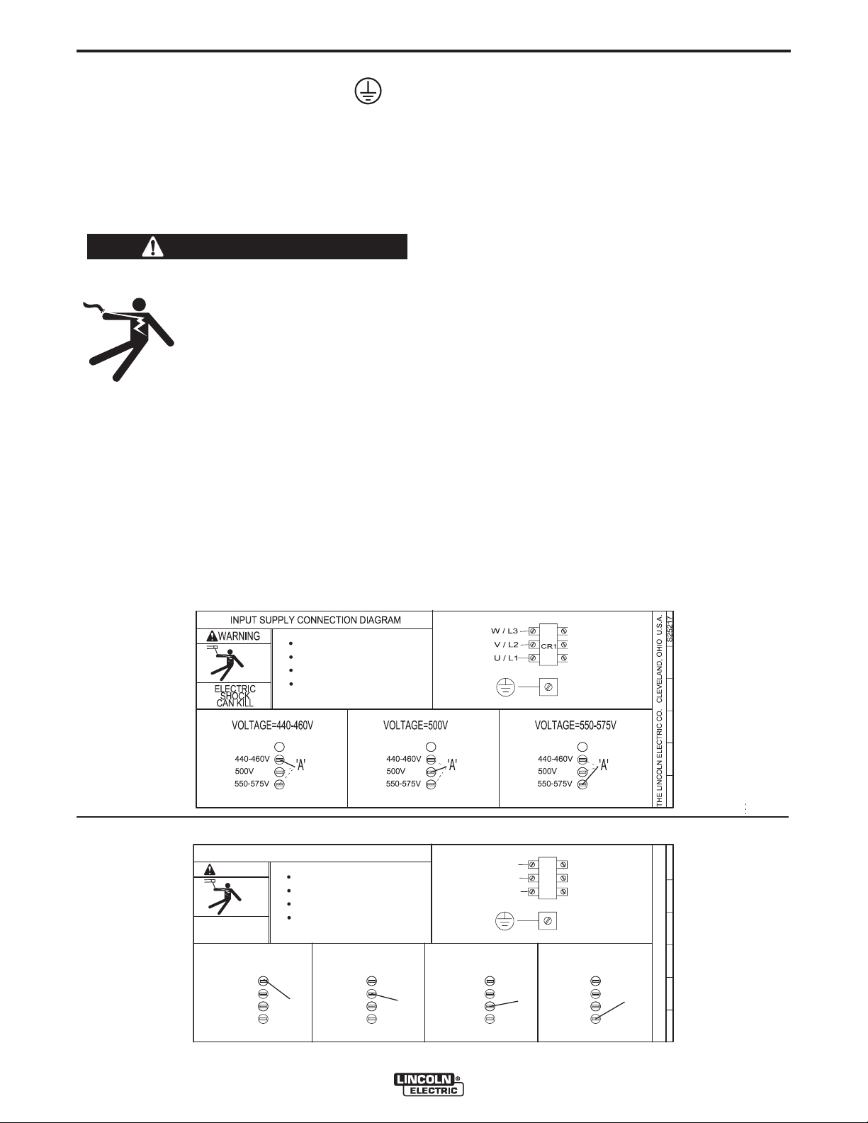
XA
Do not operate with covers removed
Disconnect input power before servicing
Do not touch electrically live parts
Only qualified persons should install,
use or service this equipment
S26047
THE LINCOLN ELECTRIC CO. CLEVELAND, OHIO U.S.A.
VOLTAGE=440-460V
'A'
A
500V
U / L1
V / L2
CR1
W / L3
INPUT SUPPLY CONNECTION DIAGRAM
550-575V
ELECTRIC
SHOCK
CAN KILL
WARNING
Do not operate with covers removed
Disconnect input power before servicing
Do not touch electrically live parts
Only qualified persons should install,
use or service this equipment
440-460V
VOLTAGE=500V
'A'
500V
550-575V
440-460V
VOLTAGE=550-575V
'A'
500V
550-575V
440-460V
VOLTAGE=380-415V
'A'
500V
550-575V
440-460V
380-415V 380-415V 380-415V 380-415V
INSTALLATION
INPUT AND GROUND CONNECTIONS
MACHINE GROUNDING
The frame of the welder must be grounded. A ground
terminal marked with the symbol shown is located
inside the reconnect / input access door for this purpose. See your local and national electrical codes for
proper grounding methods.
INPUT CONNECTION
WARNING
A-3
I
NPUT FUSE AND SUPPLY WIRE
CONSIDERATIONS
Refer to Specifications page for recommended fuse and
wire sizes. Fuse the input circuit with the recommended
super lag fuse or delay type breakers (also called "inverse
time" or "thermal/magnetic" circuit breakers). Choose input
and grounding wire size according to local or national electrical codes. Using fuses or circuit breakers smaller than
recommended may result in "nuisance" shut-offs from
welder inrush currents, even if the machine is not being
used at high currents.
ELECTRIC SHOCK can kill.
• Only a qualified electrician should
connect the input leads to the
Power Wave. Connections should
be made in accordance with all
local and National Electrical
Codes and the connection diagram located on the inside of the
reconnect / input access door of
the machine. Failure to do so may
result in bodily injury or death.
-----------------------------------------------------------------------
Use a three-phase supply line. A 1.75 inch (45 mm)
diameter access hole for the input supply is located on
the case back. Connect L1, L2, L3 and ground
according to the Input Supply Connection Diagram.
Reconnect Diagram for K2344-1 Power Wave AC/DC 1000
INPUT VOLTAGE SELECTION
Welders are shipped connected for the highest input voltage
listed on the rating plate. To move this connection to a different input voltage, see the diagram located on the inside
of the input access door, or the Reconnect Diagram K23441 and K2344-2 shown below. If the Auxiliary lead (indicated
as ‘A’) is placed in the wrong position, there are two possible results. If the lead is placed in a position higher than the
applied line voltage, the welder may not come on at all. If
the Auxiliary lead is placed in a position lower than the
applied line voltage, the welder will not come on, and the
two circuit breakers in the reconnect area will open. If this
occurs, turn off the input voltage, properly conne
iliary lead, reset the breakers, and try again.
ct the aux-
Reconnect Diagram for K2344-2 Power Wave AC/DC 1000 ("CE – ready")
POWER WAVE® AC/DC 1000
Page 14

A-4
INSTALLATION
SYSTEM CONNECTION
System Overview
The Power Wave AC/DC 1000 power source is
designed to be a part of a modular welding system
typically controlled by a Power Feed 10A Controller
or customer supplied Programmable Logic
Controller (PLC). Each welding arc may be driven by
a single power source or by a number of power
sources connected in parallel. The actual number of
power sources per arc will vary depending on the
application. When only one power source is required
for an arc group, it must be configured as a Master.
When multiple parallel machines are required, one is
designated as the Master and the rest as Slaves. The
Master controls the AC switching for the arc group,
and the Slaves respond accordingly.
When employed in a multi-arc AC system it is beneficial to synchronize the arcs to each other. The Master
for each arc can be configured to follow a dedicated
external synchronization signal to determine its frequency and balance. The optional Power Wave
System Interface provides the means to synchronize
the AC wave shapes of up to four different arcs to a
common carrier frequency. This frequency can range
from 10 hertz to 300 hertz, with the most practical
range being 10 to 100 hertz. It can also control the
phase angle between arcs to reduce the effects of
welding related issues such as "Arc Blow".
The arc to arc phase relationship is determined by the
timing of each arc’s "sync" signal relative to the "sync"
signal of ARC 1.
A-4
A PLC interface is an alternate method of control for
larger systems. The PLC is typically connected via
DeviceNet directly to the Power Wave System
Interface, and the Master power source of each arc
group in the system.
The following list of Recommended and Optional
equipment is included as a reference for the following connection diagrams. The connection diagrams
describe the layout of three typical systems. Each
diagram has a step by step Installation Checklist.
Additionally, a dedicated diagram has been provided
detailing the parallel connection of machines for
extra output capacity which can be applied to the
system diagrams as required.
In a typical multi-arc system, each arc is controlled by
its own Power Feed 10A Controller. The basic characteristics of the individual arcs such as WFS, amplitude, and offset are set locally by each arc’s dedicated
controller. The frequency, balance, and phase shift
parameters of each arc are controlled by the Power
Feed 10A Controller for ARC 1, which must be connected to its Master through the Power Wave System
Interface (see multi-arc Connection Diagrams on the
next few pages).
POWER WAVE® AC/DC 1000
Page 15

A-5
System
Identifier
Part No.
INSTALLATION
RECOMMENDED EQUIPMENT
Description
Single Arc
4
Tandem Arc
4
Triple Arc
A-5
3,4
Power Source
Weld Cables
Head
Torch
Power Source to
Head
Control Cable
User Interface
ArcLink Digital
Communication
Cable
K2344-1
-or-
K2344-2
K2163-xx
-or-
K1842-xx
K2370-1
-or-
K2312-1
K231-xxx
K1785-xx
K2362-1
K1543-xx 5
Power Wave AC/DC 1000 Power Source
Welding Power Cables
Power Source to contact Nozzle,
and Power Source to Work
K2163 Series cables sold in pairs.
K1842 Series cables sold individually.
See Price Book for details and bulk cable
availability.
Power Feed 10S Head for 3/32 to 7/32 in. solid
wire (includes hopper, wire straightener, cross
seam adjuster, head mounting hardware, and 2 -
5ft 4/0 weld cables).
Power Feed 10S Head for 3/32 to 7/32 in. solid
wire (fixture builder's head, with wire straightener -
insulators not included).
Submerged Arc Contact Nozzle Assembly
Feeder Control Cable (14 pin).
Power Feed 10A Controller
ArcLink Control Cables (5 pin).
Single Arc:
(1) PF-10A Controller to the power source
Tandem Arc:
(1) Lead Arc to System Interface
(2)System Interface to Lead Arc PF-10A
Controller
(3) Trail Arc to Trail Arc PF-10A Controller
Triple Arc:
(1) Lead Arc to System Interface
1
1
Refer to "Output Cable Guidelines"
for recommended size and quantity
2
1
1
2
1
2,4
1
1
1
2
2
2
2
2
2
2,4
2
3
1
3
2
3
3
2
3
---
1
PLC (w/ User
Interface)
DeviceNet Cables
and Accessories
System Interface
System Interface
to Power Source
Control Cable
Notes:
1. "Recommended Quantity" assumes one power source per arc. Multiple power sources may be used to increase the output capacity per arc (see "Connection Diagram - Parallel
Machines").
2. Control Cable connections only required at the Master of each parallel power source arc grouping.
3. Can be expanded to 4 or more arcs (Note: The System Interface can currently only synchronize up to four AC arc groupings).
4. The triple arc system is an economical breakpoint for a PLC Interface. It does not preclude the use of a PLC for single or tandem arc systems, nor PF-10A's from being used to control
multiple arc systems with greater than two arcs.
5. Cables can be connected end to end to extend length.
Customer
Supplied
Automation
Department or
Customer
Supplied
K2282-1
K1795-xx 5
Programmable Logic Controller
(DeviceNet compatible)
DeviceNet Cables, Tees, and Terminators (5 pin)
sealed "mini style") form a trunk style network connecting PLC to each power source and the System
Interface.
For additional information refer to the "DeviceNet
Cable Planning and Installation Manual" (Allen
Bradley publication DN-6.7.2).
Power Wave System Interface provides the
means to synchronize the AC wave shapes of up
to four different arcs to a common carrier frequen-
cy, and control the phase angle between them to
reduce the effects of "Arc Blow".
Control Cable (22 pin) connects between each
power source and the System Interface.
---
---
---
---
---
4
1
Cables, Tees,
and
---
Terminators
as required
per Triple Arc
Connection
Diagram
2
1
2
2
2
1
2
3
POWER WAVE® AC/DC 1000
4
Page 16

A-6
System
Identifier
Part No.
INSTALLATION
OPTIONAL EQUIPMENT
Description
A-6
Ethernet Network
Equipment
Personal
Computer
Travel Carriage
Travel Carriage
(High Capacity)
Controller
Mounting Bracket
User Interface
Horizontal
Adjuster
Vertical Adjuster
Wire Reel
Mounting (single)
Customer
Supplied
Customer
Supplied
K325-x
K325-HCx
K2462-1
K96
K29
K299
Ethernet Switch, Cables, etc. required for arcs > 1000A, or for use of Power Wave
Submerged Arc Utilities software package.
IBM Compatible PC (Windows NT SP6, Windows 2000, Windows XP, or greater)
required for use with Power Wave Submerged Arc Utilities software package.
TC-3 Self-Propelled Travel Carriage for traversing standard carriage
beam (per G1458)
TC-3 Self-Propelled High Capacity Travel Carriage for traversing standard carriage
beam (per G1458)
PF-10A Mounting Bracket mounts PF-10A Controller to left side of TC-3 carriage.
Brackets can be cascaded to accommodate more than one controller.
Note: Bracket uses mounting holes reserved for K299 Wire Reel Assembly
(see Wire Reel Mounting options for additional information).
Horizontal Lift Adjuster provides 2" (51mm) crank adjustment of horizontal head position.
Vertical Lift Adjuster provides 4" (102mm) crank adjustment of vertical head position.
Also provides 3.37" (95mm) in-and-out horizontal adjustment with movable stops for
repeatability.
Wire Reel Assembly accommodates one 50-60 lb (22.7-27.2 kg) coil, includes mounting
spindle and braking system. Mounts to left side of TC-3 Std. or High Capacity Travel
Carriage (K325-x).
Cannot be mounted to TC-3 when K2462-1 PF-10A Mounting Bracket is used (use K390
instead).
Wire Reel
Mounting (dual)
Mounting for Dual
Head
Flux Hopper
Flux Hopper
Remote Wire
Drive Module
K390
K387
K219
K389
K2626-1
Electrode Reels and Mountings for mounting up to two 50-60 lb (22.7-27.2 kg) coils,
includes mounting spindle and braking system. Mounts to top of TC-3 High Capacity
Travel Carriage (K325-HCx). Does not interfere with K2462-1 PF-10A Mounting Bracket.
Tandem Arc Framework includes hex style framework and mounting hardware to attach
two PF-10S or PF-10SF heads directly to a high capacity TC-3 carriage, or user supplied
fixture or gantry.
Flux Hopper with electric flux valve for Submerged Arc welding.
Flux Hopper with electric flux valve, for K387 tandem mounting. Mounts directly to hex
crossbar.
For wire drive applications greater than 100ft.
POWER WAVE® AC/DC 1000
Page 17
A-7
Wire Feeder (14 Pin)
A
rclink (5 Pin)
Arclink Connection
K
2362-1
Wire Reel
and Mounting
Work Piece
K
231-XXX
Head
* Work Cable(s)
* Electrode Cable(s)
K1785-XX
Wire Feeder
Control Cable
K1543-XX
Arclink Control Cable
Work Sense
Lead (21)
Electrode Sense
Lead (67)
67 Lead
21 Lead
14 Pin Connector
Flux Hopper
C
onnection
T
ravel Carriage
Connection
* Refer to "Output Cable Guidelines" for recommended cable size.
Work Studs
E
lectrode Studs
Connection Diagram- Typical Single Arc System (Power Feed 10A Controller)
INSTALLATION
A-7
POWER WAVE® AC/DC 1000
Page 18

A-8
INSTALLATION
STEP BY STEP INSTALLATION CHECKLIST
SINGLE ARC SYSTEM CHECKLIST – (PF-10A CONTROLLED, 1 POWER SOURCE)
(as shown in the Connection Diagram "Typical Single Arc System")
Place Power Wave in suitable operating location.
Mount PF10A Controller.
Install PF10S Wire Drive and other accessories in their operating location.
A-8
Connect K1785-xx Wire Feeder Control Cable (14 pin) between the Power Wave and Wire Drive.
Connect K1543-xx ArcLink Control Cable (5 pin) between Power Wave and PF10A.
Configure / Install sense leads.
Connect / Install welding cables per recommended "Output Cable Guidelines."
Open all Power Wave front panel and configure DIP switch settings per "Internal Controls" section.
Connect input power to Power Wave per recommended guidelines.
Turn on Power Wave, and verify all system Status Lights are solid green.
NOTES:
(1) ArcLink and Wire Feeder control cable connections are only required at the Master power source of each
arc grouping. For additional information see the "Extra Capacity Parallel Connection Checklist."
(1)
(1)
POWER WAVE® AC/DC 1000
Page 19
A-9
AA
RR
CC
22
AA
RR
CC
11
AA
RR
CC
11
A
A
R
R
CC
22
AA
RR
CC
11
AA
RR
CC
22
A
A
RR
CC
11
AA
RR
CC
22
SS
Y
Y
SS
TT
EE
MM
II
NN
TT
EE
RR
FF
AA
CC
EE
Master Input (S12)
Connects to System
Interface
Arclink Connection
21 Lead
67 Lead
* Work Cables
K1785-XX
Wire Feeder
Control Cabl
es
K1795-XX Cables
* Electrode Cables
Arc
link (5 Pin)
Wire Feeder
(
14 Pin)
K2282-1
K
236
2-1
Head
K
231-
XXX
Work Piece
14 Pin Connector
Work Studs
Electrode Studs
Arc
lin
k Out put
Work Sense
Lead (21)
Electrod
e
Sense
Lead (67)
* Refer to "Output Cable guidelines" for recommended cable size.
K15
43-XX
Arc
lin
k Contro
l Ca
bl
es
Connection Diagram- Typical Tandem Arc System ( Power Feed 10A Controller)
Arc
link Input
Wir
e Reel
and Mo
untings
Flux Hopper
Connection
Travel Carr
iage
Connection
INSTALLATION
A-9
POWER WAVE® AC/DC 1000
Page 20

A-10
INSTALLATION
STEP BY STEP INSTALLATION CHECKLIST
TANDEM ARC SYSTEM CHECKLIST – (PF-10A CONTROLLED, 1 POWER SOURCE PER ARC)
(as shown in the Connection Diagram "Typical Tandem Arc System”)
Place Power Waves in suitable operating location.
Mount PF10A Controllers.
Install PF10S Wire Drives and other accessories in their operating location.
Mount Power Wave System Interface.
A-10
Connect K1785-xx Wire Feeder Control Cable (14 pin) between each Power Wave and Wire Drive.
Connect K1543-xx ArcLink Control Cables (5 pin) from Power Wave #1 to the System Interface input, and
from the System Interface output to the PF10A Controller for ARC #1.
Connect K1543-xx ArcLink Control Cable (5 pin) between Power Wave #2 and the PF10A Controller for ARC
(1)
#2.
Connect K1795-xx System Control Cables (22 pin) between each Power Wave and the System Interface.
Configure / Install sense leads.
Connect / Install welding cables per recommended "Output Cable Guidelines."
Open all Power Wave front panels and configure DIP switch settings per "Internal Controls" section.
Connect input power to Power Waves per recommended guidelines.
Turn on Power Waves, and verify all system Status Lights are solid green.
NOTES:
(1) ArcLink and Wire Feeder control cable connections are only required at the Master power source of each
arc grouping. For additional information see the "Extra Capacity Parallel Connection Checklist."
(1)
(1)
(2)
(2) The "ARC" (formerly "PHASE") connections from the System Interface are only required for the Master
power source of each arc grouping. For additional information see the "Extra Capacity Parallel Connection
Checklist."
POWER WAVE® AC/DC 1000
Page 21
A-11
AA
RR
CC
11
AA
RR
CC
2
2
AA
RR
CC
22
AA
RR
CC
33
AA
RR
CC
11
AA
RR
CC
3
3
AA
RR
CC
11
AA
RR
CC
22
AA
RR
CC
33
SS
YY
SS
TT
EE
MM
II
NN
TT
EE
RR
FF
A
A
CC
EE
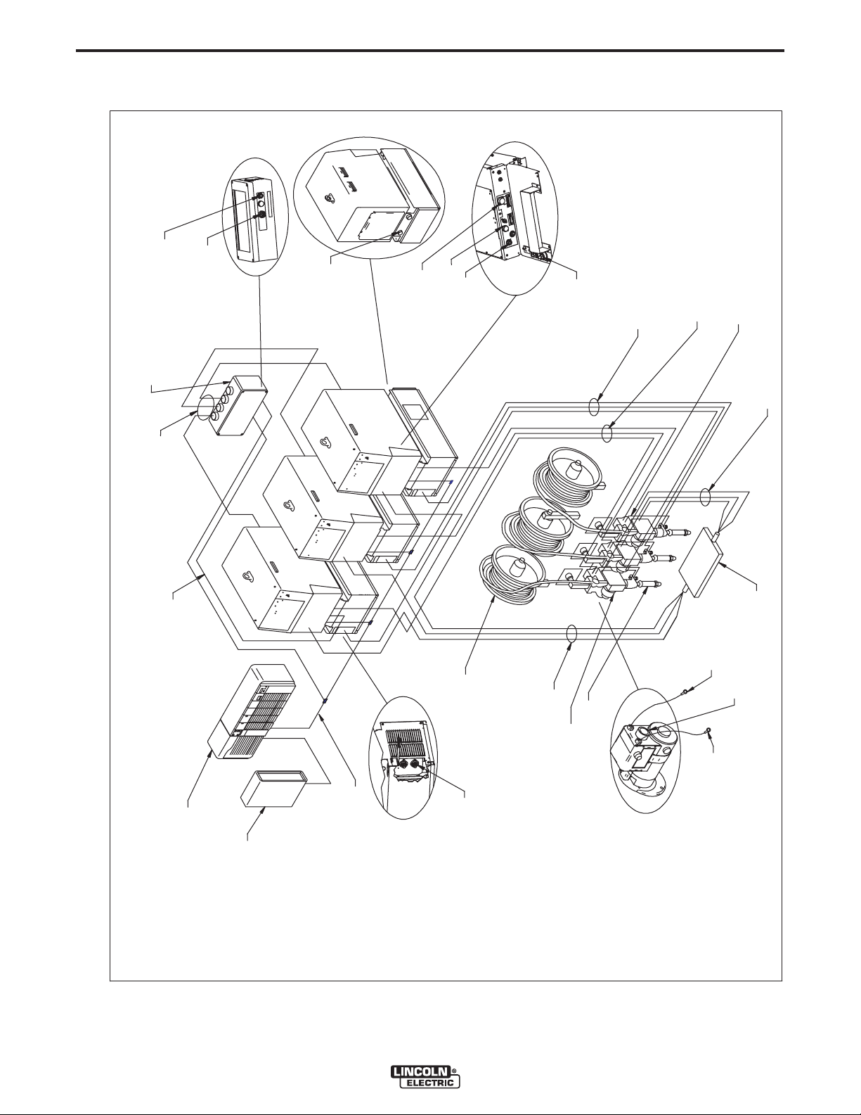
Connection Diagram- Typical Triple Arc System (DeviceNet PLC Controller)
67 Lead
21 Lead
14 Pin Co
nnector
* Work Cables
Work P
iece
Work
S
ense L
eads (2
1)
* E
lectrod
e Cables
* Refer to "Output Cable Guidelines" for recommended cable size.
Head
K
231-
XXX
DeviceNet Cable Network
K179
5-XX Cabl
es
K
154
3-XX
Arclink Co
ntrol Cab
le
K1785-
XX
Wire Feeder
Control Cables
Arclink Input
Wir
e Feeder
(14 Pin)
Arclink (5
P
in)
Work Stu
ds
Electrod
e Studs
Wire Reel
and Mountings
PLC Contro
ller
E
lectrod
e Sense L
ead (6
7)
Master Input (S1
2)
Connects to System
Interface
K2282-1
User Interface
DeviceNet
Device
Net
(5 Pin)
INSTALLATION
A-11
POWER WAVE® AC/DC 1000
Page 22

A-12
INSTALLATION
STEP BY STEP INSTALLATION CHECKLIST
TRIPLE ARC SYSTEM CHECKLIST – (DEVICENET PLC CONTROLLED, 1 POWER SOURCE PER ARC)
(as shown in the Connection Diagram "Typical Triple Arc System”)
Place Power Waves in suitable operating location.
Mount DeviceNet PLC Controller and User Interface.
Install PF10S Wire Drives and other accessories in their operating location.
Mount Power Wave System Interface.
A-12
Connect K1785-xx Wire Feeder Control Cable (14 pin) between each Power Wave and Wire Drive.
Connect K1543-xx ArcLink Control Cable (5 pin) from ARC #1 power source to the System Interface input.
Connect K1795-xx System Control Cables (22 pin) between each Power Wave and the appropriate System
Interface "ARC" (formerly "PHASE") outputs.
Connect the System Interface and each power source to the PLC via the DeviceNet network.
Configure / Install sense leads.
Connect / Install welding cables per recommended "Output Cable Guidelines."
Open all Power Wave front panels and configure DIP switch settings (including the DeviceNet MAC ID and
Baud Rate settings) per "Internal Controls" section.
Connect input power to Power Waves per recommended guidelines.
Turn on Power Waves, and verify all system Status Lights are solid green.
NOTES:
(1) ArcLink, DeviceNet and Wire Feeder control cable connections are only required at the Master power source
of each arc grouping. For additional information see the "Extra Capacity Parallel Connection Checklist."
(2)
(1)
(1)
(1)
(2) The "ARC" (formerly "PHASE") connections from the System Interface are only required for the Master
power source of each arc grouping. For additional information see the "Extra Capacity Parallel Connection
Checklist."
POWER WAVE® AC/DC 1000
Page 23
A-13
MM
AA
SS
TT
EE
RR
SS
LL
AA
VV
EE
K
179
5-XX C
ables
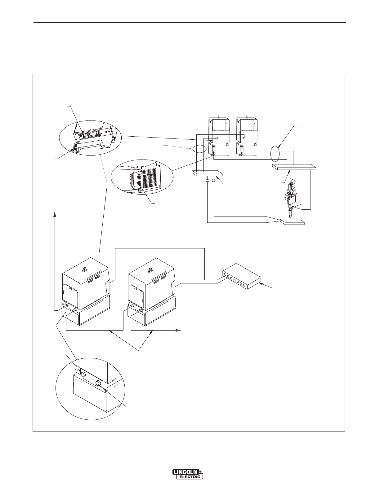
Connection Diagram - Parallel
Machines
(Example depicts a single arc grouping, and may be repeated for each arc in the system)
Connect additional
SLAVE
machines as required to reach
desired capacity.
Note: Each arc is limited to 5
SLAVE machines per MASTER
(6 machines total)
S
12 (Input)
S13 (Output)
Connect to optional
K2282-1 System Interface
for Synchronized
Multiple Arc Applications
E
thernet
Note:
Ethernet connectivity allows machines to share critical
parameter information. Proper configuration requires the use of
the
Weld Manager and
SubarcCellConfig
software utilities.
C
ommon bus connections
recommended for
excessive cable length
applications. (Locate
close to power sources.)
*
Electrode
Cables
* Work Cables
Work
E
lectrode
Front view o
f
machines
Rea
r view of machines
* Refer to "Output Cable Guidelines" for recommended cable size.
Ethernet S
witch
INSTALLATION
A-13
POWER WAVE® AC/DC 1000
Page 24

A-14
INSTALLATION
STEP BY STEP INSTALLATION CHECKLIST
EXTRA CAPACITY PARALLEL CONNECTION
(as shown in the Connection Diagram "Parallel Machines”)
Follow all steps of Single, Tandem, or Triple Arc checklists.
Be sure input power is disconnected prior to following the remaining steps.
Control Cable Connections:
PF-10S Connections:
Each PF-10S must be connected to the Master power source of its associated arc.
PF-10A Controlled Systems:
Each PF-10A Controller must be connected to the Master power source of its arc via a K1543-xx
ArcLink Control Cable (5 pin), but should not be connected to the Slave(s).
In a multi-arc system, the System Interface must also be connected to the ARC #1 Master power
source via a K1543-xx ArcLink Control Cable (5 pin).
A-14
DeviceNet PLC Controlled Systems:
Only the Master power source of each arc should be connected to the PLC Controller via the
DeviceNet network.
In a multi-arc system, the System Interface must connected to the PLC via the DeviceNet network.
It must also be connected to the ARC #1 Master power source via a K1543-xx ArcLink Control
Cable (5 pin).
Connect K1795-xx System Control Cables (22 pin) between the Master and Slaves of each arc grouping per
the Parallel Machines Connection Diagram.
Connect / Install welding cables per the recommended "Output Cable Guidelines" and the "Parallel
Machines Connection Diagram" for each arc grouping.
Configure / Install sense leads (the sense lead configuration of all machines in a given parallel arc grouping
must be the same).
Open Power Wave front panels and configure DIP switch settings per "Internal Controls" section.
Connect Power Wave to LAN (Local Area Network). See "Connection Between Power Source and Ethernet
Network."
Connect input power to Power Waves per recommended guidelines.
Turn on Power Waves.
Configure network settings using Weld Manager software utility (follow instructions provided).
Run the Submerged Arc Cell Configuration software utility to configure the Master / Slave relationships of
each arc grouping (follow instructions provided).
POWER WAVE® AC/DC 1000
Page 25

A-15
WORK PIECE
COMMON CONNECTION
(LOCAT ED CLOSE TO
POWER SOUR
CES)
Common Connection Diagram
INSTALLATION
A-15
ELECTRODE AND WORK
CONNECTIONS
General Guidelines
The unique switching structure of the Power Wave
AC/DC 1000 allows it to produce DC positive, DC
negative or AC output waveforms without repositioning the work and electrode leads. Additionally, no DIP
switch changes are required to switch between the different polarities. All of this is controlled internally by
the Power Wave AC/DC 1000, and based exclusively
on the weld mode selection.
The following recommendations apply to all output
polarities and weld modes:
• Select the appropriate size cables per the
"Output Cable Guidelines" below. Excessive voltage drops caused by undersized welding cables
and poor connections often result in unsatisfactory
welding performance. Always use the largest welding cables (electrode and work) that are practical,
and be sure all connections are clean and tight.
Note: Excessive heat in the weld circuit indicates
undersized cables and/or bad connections.
For parallel applications with excessive electrode
cable lengths, a common bus connection should be
used. The common electrode connection serves to
minimize voltage drops associated with resistive losses in the electrode path. It should be made of copper,
and located as close as possible to the power
sources. (See "Connection Diagram – Parallel
Machines")
Work Connections
Connect a work lead of sufficient size and length (Per
Table 1) between the "work" stud (located beneath the
spring loaded output cover on the top, front of the
machine) and the work piece. For convenience, the
work lead can be routed along the left cable tray, and
out the back of the machine. Be sure the connection
to the work makes tight metal-to-metal electrical contact.
For parallel and/or multiple arc applications with
excessive ground path lengths, a common work connection bus should be used. The common work connection serves to minimize voltage drops associated
with resistive losses in the ground paths. It should be
made out of copper, and located as close as possible
to the power sources (See Common Connection
Diagram).
• Route all cables directly to the work and wire
feeder, avoid excessive lengths and do not coil
excess cable. Route the electrode and work cables
in close proximity to one another to minimize the
loop area and therefore the inductance of the weld
circuit.
• Always weld in a direction away from the work
(ground) connection.
Total Cable Length
Electrode and Work
0 (0) to 250 (76.2)
0 (0) to 250 (76.2)
Electrode Connections
Connect an electrode cable of sufficient size and
length (Per Table A.1) to the "electrode" stud on the
power source (located behind the cover plate on the
lower left side). For convenience, the cable can be
routed down through the two holes in the left cable
tray before being connected to the output terminals.
Connect the other end of the electrode cable to the
wire drive feed plate on the wire feeder. Be sure the
connection to the feed plate makes tight metal-tometal electrical contact.
TABLE A.1 - Output Cable Guidelines
ft (m)
Combined
Duty Cycle
80%
100%
Number of
Parallel Cables
2
3
Cable Size
Copper
4/0 (120 mm
3/0 (95 mm
2
)
2
)
POWER WAVE® AC/DC 1000
Page 26

A-16
B
A
C
POWER
WAVE
FIGURE A.2
WORK
INSTALLATION
CABLE INDUCTANCE, AND ITS EFFECTS
ON WELDING
Excessive cable inductance will cause the welding
performance to degrade. There are several factors
that contribute to the overall inductance of the cabling
system including cable size, and loop area. The loop
area is defined by the separation distance between
the electrode and work cables, and the overall welding
loop length. The welding loop length is defined as the
total of length of the electrode cable (A) + work cable
(B) + work path (C) (see Figure A.1 below). To minimize inductance always use the appropriate size
cables, and whenever possible, run the electrode and
work cables in close proximity to one another to minimize the loop area. Since the most significant factor in
cable inductance is the welding loop length, avoid
excessive lengths and do not coil excess cable. For
long work piece lengths, a sliding ground should be
considered to keep the total welding loop length as
short as possible.
REMOTE SENSE LEAD CONNECTIONS
A-16
Electrode Voltage Sensing
The remote ELECTRODE sense lead (67) is built into
the wire feeder control cable (K1785) and accessible
at the wire drive. It should always connected to the
wire drive feed plate when a wire feeder is present.
Enabling or disabling electrode voltage sensing is
application specific, and automatically configured
through software.
Work Voltage Sensing
For most applications the use of a remote work voltage sense lead is recommended. The Power Wave
AC/DC 1000 is shipped from the factory with the
remote work voltage sense lead enabled. It must be
attached to the work as close to the weld as practical,
but out of the weld current path. For more information
regarding the placement of remote work voltage
sense leads, see the section entitled "Voltage Sensing
Considerations for Multiple Arc Systems." The remote
WORK sense lead (21) can be accessed at one of two
locations. Either at the wire drive via the wire feeder
control cable (K1785), or at the four-pin WORK sense
lead connector located under the spring loaded output
cover. Whenever possible, use the WORK sense lead
that is built into wire feeder control cable (K1785)
since it is closely coupled with the ELECTRODE
sense lead and will tend to be more immune to electrical noise. If it is not possible to sense the WORK voltage near the feeder, the four-pin WORK sense lead
connector at the power source should be used (a plug
and pigtail assembly is provided for this purpose).
Voltage Sensing Overview
The best arc performance occurs when the Power
Wave AC/DC 1000 has accurate data about the arc
conditions. Depending upon the process, inductance
within the electrode and work cables can influence the
voltage apparent at the studs of the welder, and have
a dramatic effect on performance. To counteract this
negative effect, remote voltage sense leads are used
to improve the accuracy of the arc voltage information
supplied to the control pc board.
There are several different sense lead configurations
that can be used depending on the application. In
extremely sensitive applications it may be necessary
to route cables that contain the sense leads away
from the electrode and work welding cables.
CAUTION
If the remote voltage sensing is enabled but the
sense leads are missing, improperly connected, or
if the electrode polarity switch is improperly configured extremely high welding outputs may
occur.
------------------------------------------------------------------------
POWER WAVE® AC/DC 1000
CAUTION
Never connect the WORK sense lead at two different locations.
WARNING
ELECTRIC SHOCK can kill.
• Do not touch electrically live parts or
electro des with yo ur s kin or wet
clothing.
• Insulate yourself from the work and
ground.
• Always wear dry insulating gloves.
-----------------------------------------------------------
Some simplified applications may perform adequately
by sensing the work voltage directly at the WORK
STUD without the use of a remote work voltage sense
lead. If a remote work voltage sense lead is not used,
it must be disabled as follows:
1. Turn off power to the power source at the disconnect switch.
2. Remove the front cover from the power source.
Page 27

A-17
1 2 3 4 5 6 7 8
O
N
DIRECTION
OF TRAVEL
CONNECT ALL
WORK LEADS AT
THE BEGINNING
OF THE WELD.
CONNECT ALL SENSE
LEADS AT THE END
OF THE WELD.
c. Locate the 8-position DIP switch on the control
board and look for switch 8 of the DIP switch.
INSTALLATION
A-17
VOLTAGE SENSING CONSIDERATIONS FOR
MULTIPLE ARC SYSTEMS
d. Using a pencil or other small object, slide the
switch to the OFF position if the work sense lead
is NOT connected. Conversely, slide the switch
to the ON position if the work sense lead is present.
e. Replace the cover and screws. The PC board will
read the switch at power up, and configure the work
voltage sense lead appropriately.
Voltage Sensing for "Slave" machines
If "Slave" machines are configured to use remote voltage sensing they receive these signals directly from
the "Master" machine. The K1795 control cable used
for parallel connection of machines contains both the
ELECTRODE sense lead (67) and the WORK sense
lead (21). No other external sense lead connections
are required for "Slave" machines.
NOTE: All of the machines of a given arc group
(both Master and Slaves) must have their
work voltage sensing configured identically. All must either use a remote lead or
sense directly from the stud. For additional information see the "Work Voltage
Sensing" section of this document.
FIGURE A.2
Special care must be taken when more than one arc
is welding simultaneously on a single part. Multiple
arc applications do not necessarily dictate the use of
remote work voltage sense leads, but they are strongly recommended.
If Sense Leads ARE NOT Used:
• Avoid common current paths. Current from adja-
cent arcs can induce voltage into each others current paths that can be misinterpreted by the power
sources, and result in arc interference.
If Sense Leads ARE Used:
• Position the sense leads out of the path of the
weld current. Especially any current paths com-
mon to adjacent arcs. Current from adjacent arcs
can induce voltage into each others current paths
that can be misinterpreted by the power sources,
and result in arc interference.
• For longitudinal applications, connect all work
leads at one end of the weldment, and all of the
work voltage sense leads at the opposite end of the
weldment. Perform welding in the direction away
from the work leads and toward the sense leads.
(See Figure A.2)
POWER WAVE® AC/DC 1000
Page 28

A-18
POWER
SOURCE
#2
POWER
SOURCE
#1
POWER
SOURCE
#1
POWER
SOURCE
#2
POWER
SOURCE
#2
POWER
SOURCE
#1
INSTALLATION
A-18
• For circumferential applications, connect all work leads on one side of the weld joint, and all of the work volt-
age sense leads on the opposite side, such that they are out of the current path.
POWER WAVE® AC/DC 1000
Page 29

A-19
INSTALLATION
A-19
CONTROL CABLE CONNECTIONS
General Guidelines
Genuine Lincoln control cables should be used at
all times (except where noted otherwise). Lincoln
cables are specifically designed for the communication and power needs of the Power Wave / Power
Feed systems. Most are designed to be connected
end to end for ease of extension. However, it is recommended that the total length not exceed 100 feet
(30.5 m). The use of non-standard cables, especially
in lengths greater than 25 feet, can lead to communication problems (system shutdowns), poor motor
acceleration (poor arc starting), and low wire driving
force (wire feeding problems). Always use the shortest
length of control cable possible, and DO NOT coil
excess cable.
Regarding cable placement, best results will be
obtained when control cables are routed separate
from the weld cables. This minimizes the possibility of
interference between the high currents flowing
through the weld cables, and the low level signals in
the control cables. These recommendations apply to
all communication cables including optional DeviceNet
and Ethernet connections.
COMMON EQUIPMENT CONNECTIONS
Connection Between Power Source and Power
Feed 10S Series Wire feeder (K1785 - Control
Cable). The 14-pin wire feeder control cable connects
the power source to the wire drive. If there is more
than one power source per arc, it connects from the
wire drive to the power source designated as the
Master. It contains all of the necessary signals to drive
the motor and monitor the arc, including the motor
power, tachometer, and arc voltage feedback signals.
The wire feeder connection on the Power Wave
AC/DC 1000 is located under the spring loaded output
cover on the case front. The control cable is keyed
and polarized to prevent improper connection. For
convenience, the control cables can be routed along
the right channel of the Power Wave, out the back,
and to the wire feeder. Control cables SHOULD NOT
be routed through the same (left) channel as the welding cables.
Connection Between Power Source and Power
Feed 10A Controller (K1543 – ArcLink Control
Cable). Single and tandem arc systems are typically
controlled by a Power Feed 10A Controller (K2362-1).
In a tandem, or multi-arc system, each arc requires its
own dedicated Power Feed 10A (PF-10A).
The 5-pin ArcLink control cable connects the power
source to the PF-10A. If there is more than one power
source per arc, it connects from the PF-10A to the
power source designated as the Master for that arc.
The control cable consists of two power leads, one
twisted pair for digital communication, and one lead
for voltage sensing. The ArcLink connection on the
Power Wave AC/DC 1000 is located under the spring
loaded output cover on the case front. The control
cable is keyed and polarized to prevent improper connection. For convenience, the control cables can be
routed along the right channel of the Power Wave, out
the back, and to the PF-10A. Control cables SHOULD
NOT be routed through the same (left) channel as the
welding cables.
In multiple arc systems equipped with a Power Wave
System Interface (K2282-1), and controlled by PF-10A
controllers, the system interface must be connected to
the ArcLink network of the ARC1 Master power
source. See the "Tandem Arc Connection Diagram"
for detailed information.
Connections Between Power Source and Optional
DeviceNet Programmable Logic Controller(PLC). It
is sometimes more practical and cost effective to use
a custom PLC interface to control a multi-arc system
(refer to the "DeviceNet Configuration" section for
interface information). The Power Wave AC/DC 1000
is equipped with a 5-pin DeviceNet mini style receptacle for this purpose. The receptacle is located under
the spring loaded output cover on the case front. The
DeviceNet cable is keyed and polarized to prevent
improper connection. For convenience, it can be routed along the right channel of the Power Wave, and
out the back. DeviceNet cables SHOULD NOT be
routed through the same (left) channel as the welding
cables.
In a typical system, a DeviceNet connection is made
between the master power source of each arc, and
the PLC interface. When a Power Wave System
Interface (K2282-1) is used to synchronize the arcs, it
must also be connected to the DeviceNet network. For
best results, route DeviceNet cables away from weld
cables, wire drive control cables, or any other current
carrying device that can create a fluctuating magnetic
field. DeviceNet cables must be sourced locally by the
customer. For additional guidelines refer to the
"DeviceNet Cable Planning and Installation Manual"
(Allen Bradley publication DN-6.7.2).
POWER WAVE® AC/DC 1000
Page 30

A-20
INSTALLATION
A-20
Connections Between Multiple Power Sources
Run in Parallel (K1795 - Control Cable). To increase
the output capacity for a given arc, the output studs of
multiple Power Wave AC/DC 1000 machines can be
connected in parallel. The parallel machines utilize a
master/slave control scheme to distribute the load and
coordinate AC switching. The 22 pin parallel control
cable contains all of the necessary signals to keep the
machine outputs synchronized, including polarity,
ready, kill, and arc voltage feedback signals. The
cable connects between the Master/Slave I/O connectors (S12 & S13) located on the rear of the Power
Wave AC/DC 1000. The input connector (S12) is
located on the lower left side of the case back (as
viewed from the rear), and the output connector (S13)
is located on the lower right side. The output connector (S13) on the master connects to the input connector (S12) on the slave. If needed the output connector
on the slave machine can be used to connect to the
input connector of another slave machine in a daisy
chain fashion. This connection scheme can be repeated as required until the desired output capacity is
achieved. The system is currently limited to a maximum of 5 slaves per master, or a total of 6 machines
per arc.
NOTE: In addition to the parallel control cable, parallel
connected machines also require an Ethernet
connection to share critical weld parameter
information. For more information refer to the
"Connections Between a Power Source and
Ethernet Network" section of this document.
NOTE: See Ethernet Configuration section for addi-
tional information.
Connections Between a Power Source and
System Interface (K1795 - Control Cable). When
multiple arcs need to be synchronized, a Power Wave
System Interface (K2282-1) is required. The system
interface provides a dedicated synchronization signal
for frequency and balance to each of the four ARC
(a.k.a. PHASE) receptacles. The synchronization signals for ARC1 through ARC4 can be phase shifted
with respect to one another to reduce the effects of
"arc blow" and other welding related issues. The individual synchronization signals are relayed to the master machine of their corresponding arc via a 22 pin
control cable. The control cable(s) connect between
the individual ARC receptacles on the system interface, and the Master/Slave input connector on the
master of each corresponding arc group. The
Master/Slave input connector (S12) is located on the
lower left side of the case back (as viewed from the
rear) of the Power Wave AC/DC 1000.
NOTE: In addition to the 22-pin arc synchronization
cables, the system interface also requires a
connection to the system controller either via
ArcLink for Power Feed 10A controlled systems (see "Connection Between Power
Source and Power Feed 10A Controller" ), or
via DeviceNet for PLC controlled systems (see
"Connection Between a Power Source and
Optional DeviceNet PLC Controller").
Connection Between Power Source and Ethernet
Network. Ethernet connections are required for sys-
tems with parallel connected power sources (more
than one power source per arc), or to utilize the tools
provided in the Power Wave Submerged Arc Utilities
software package. To facilitate this, the Power Wave
AC/DC 1000 is equipped with an RJ-45 Ethernet connector, which is located under the spring loaded output cover. External Ethernet equipment (cables,
switches, etc.) must be supplied by the customer. It is
critical that all Ethernet cables external to either a conduit or an enclosure are solid conductor, shielded cat
5 cable, with a drain. The drain should be grounded
at the source. The use of cat 5+, cat 5E, cat 6 or
stranded cable is not recommended. For best results,
route Ethernet cables away from weld cables, wire
drive control cables, or any other current carrying
device that can create a fluctuating magnetic field. For
additional guidelines refer to ISO/IEC 11801. Failure
to follow these recommendations can result in an
Ethernet connection failure during welding.
Connections Between a Power Source and Local
PC (RS-232 – Null Modem Cable). For diagnostic
and set up purposes it is sometimes necessary to
connect the power source directly to a PC (personal
computer). The Power Wave AC/DC 1000 is equipped
with an RS-232 DB-25 style serial connector for this
purpose. It is located under the spring loaded output
cover on the case front. RS-232 cables must be supplied by the user (Radio Shack part # 26-269; Note:
USB port adapter - part #26-183 - is also required for
PC’s equipped with USB instead of a serial port). For
best results, route the RS-232 cable away from weld
cables, wire drive control cables, or any other current
carrying device that can create a fluctuating magnetic
field.
POWER WAVE® AC/DC 1000
Page 31

A-21
D
E
F
123
4
5
6
78
9 10
11
12
G
H
I
A
B
C
+15 VDC for Trigger Group
Trigger Input
Dual Procedure Input
4 Step Input
+15 VDC for Cold Inch Group
Cold Inch Forward
Cold Inch Reverse
Gas Purge Input
+15 for shutdown group
Shutdown1 input
Shutdown2 input (Water Fault)
Reserved for future use
1
2
3
4
5
6
7
8
9
10
11
12
INSTALLATION
A-21
EXTERNAL I/O CONNECTOR
The Power Wave AC/DC 1000 is equipped with a terminal strip for making simple input signal connections.
(See Figure A.2a) The terminal strip is located underneath the spring-loaded cover, and divided into three
groups:
FIGURE A.2a
Trigger group, Cold Inch Group and Shutdown Group.
When the Power Wave AC/DC 1000 is controlled via
DeviceNet, the Trigger and Cold Inch Groups can
interfere with the welding sequence and should not be
used.
All inputs use "normally open" logic except the shutdown group. The shutdown inputs use "normally
closed" logic, and are always enabled. Shutdown2 is
typically used for signaling low flow in the water cooler. Unused shutdowns must be tied to the +15V supply for the shutdown group. Machines are shipped
from the factory with jumpers installed on both shutdown inputs. (See Figure A.3)
RECEPTACLE SPECIFICATION
Table A.2 Output Arclink Receptacle S1 (5 pin – MS style)
PIN Lead # Function
A 53 Arclink L
B 54 Arclink H
C 67A Electrode Voltage Sense
D 52 Ground(0v)
E 51 +40vdc
Table A.3 Voltage Sense Receptacle S2 (4 pin – Circular
Plastic)
PIN Lead # Function
3 21A Work Voltage Sense
Table A.4 RS232 Connector S3 (DB-25 style)
PIN Lead # Function
2 253 RS232 Receive
3 254 RS232 Transmit
4# S3 Pin5
5# S3 Pin4
6 ## S3 Pin20
20 ## S3 Pin6
7 251 RS232 Common
Notes:
1. Activating the Trigger or Cold Inch group inputs on
a system without a user interface or other means
of configuring the Weld Sequencer will result in
default values for Weld Mode, WFS and Work
point settings.
2. Trigger and Cold Inch group inputs may be redefined as "Weld Profile Selections" by Production
Monitoring software (see Production Monitoring
Literature for details)
3. On later machines, pin 12 has been redefined as a
gear ratio selection input. See “Setting the Wire
Drive Gear Ratio” for further information.
FIGURE A.3
Table A.5 DeviceNet Connector S5 (5 pin - "mini" style)
PIN Lead # Function
2 894 +24vdc DeviceNet
3 893 Common DeviceNet
4 892 DeviceNet H
5 891 DeviceNet L
Table A.6 Wire Drive Interface Receptacle S6 (14 pin – MS
style)
Pin Function
A Motor "+"
B Motor "-"
C +40 VDC for solenoid
D Solenoid input
E Tach 2A differential signal
F Single Tach Input
G +15 VDC Tach
H Tach common
I Work voltage sense lead 21
J Electrode voltage sense lead 67
K Tach 1A differential signal
L Tach 1B differential signal
M Tach 2B differential signal
N Electrode voltage sense lead 67
POWER WAVE® AC/DC 1000
Page 32

A-22
Table A.7 External I/O S7 (12 pin – terminal block)
PIN Lead # Function
1 851 +15vdc for Trigger group
2 852 Trigger input
3 853 Dual procedure input
4 854 4 step input (Disabled as of S25564-19)
5 855 +15vdc for cold inch group (Disabled as of S25564-19)
6 856 cold inch forward
7 857 cold inch reverse
8 858 gas purge input
9 859 +15vdc for shutdown group
10 860 shutdown1 input
11 861 shutdown2 input
12 862 input B
Table A.8 Master / Slave I/O and System Interface Output Receptacles (22 Pin – MS bayonet style)
Pin Master / Slave Input Master / Slave Output Optional System Interface
(S12) (S13) (ARC1, ARC2, ARC3, ARC4)
A Reserved for future use Reserved for future use --B Reserved for future use Reserved for future use --C Sync In Reserved for future use Sync Out
D Sync In Reserved for future use Sync Out
E Ready In Ready In --F Ready In Ready In --G Polarity Out Polarity Out --H Polarity Out Polarity Out --I Ground --- --J Reserved for future use Reserved for future use --K Reserved for future use Reserved for future use --L +40v (COM) Reserved for future use --M +40v ("+") Reserved for future use --N Reserved for future use Reserved for future use --P Reserved for future use Reserved for future use --R Reserved for future use Reserved for future use --S Reserved for future use Reserved for future use --T Drain (ethernet) Drain (ethernet) --U Kill Out Kill Out --V Kill Out Kill Out --W Work voltage sensing (21) Work voltage sensing (21) --X Electrode Voltage Sensing (67) Electrode Voltage Sensing (67) ---
INSTALLATION
A-22
Table A.9 Ethernet Connector S9 (8 pin – RJ-45 Style Connector / cat 5 Cable)
PIN Function
1 Transmit +
2 Transmit 3 Receive +
4 --5 --6 Receive 7 --8 ---
POWER WAVE® AC/DC 1000
Page 33

A-23
S1S1
FEFEEEDHEDHEAADD
P.P.CC.. BOA BOARRDD
EXEXTTEERRNNAL I/OAL I/O
CCOONNNNEECTORCTOR
1
2
3
4
5
6
7
8
9
10
11
12
JUMPER PIN 5
J
UMPER PIN 12
INSTALLATION
WIRE DRIVE GEAR RATIO SETTING
Changing the wirefeeder gear ratio requires a gear
change in the wire drive, and a configuration change
at the power source. The Power Wave AC/DC 1000
can be configured to support up to 4 unique gear
ratios. The gear ratio configuration is selected via a
DIP switch on the Feed Head PC Board and a jumper
on the External I/O connector (S7 - located beneath
the spring loaded output cover on the top, front of the
machine).
As shipped from the factory, the low speed (high
torque) gear is installed. To change the gear ratio of
the feeder, see the Wirefeeder Instruction Manual. To
achieve the correct speed, the power source must
also be configured for the actual gear ratio installed in
the wire drive per the instructions below:
TABLE A.9a
Ratio
142:1
95:1
57:1*
Reserved*
(Presently57:1)
Dip Switch #8
(Feed Head PCB - Bank S1)
OFF
ON
OFF
ON
External I/O Jumper
(Pin 5 to Pin 12)
* These Gear Ratios options are enabled in
S25564-11 and later Feed Head software.
ETHERNET CONFIGURATION
A-23
NO
NO
YES
YES
WARNING
ELECTRIC SHOCK can kill.
• Do not touch electrically live parts
or electrodes with your skin or wet
clothing.
• Insulate yourself from the work and
ground.
• Always wear dry insulating gloves.
WARNING
-----------------------------------------------------------
(See Figure A.3a)
1. Turn off power to the power source at the disconnect switch. All configuration changes must
be made with the power OFF.
2. Access the Feed Head board and External I/O connector to configure the power source per table
A.9a.
3. Replace the cover and screws as required. The
Feed Head PC board will "read" the new configuration at power up, and automatically adjust all control
parameters for the speed range selected.
FIGURE A.3a
Ethernet capability is provided for data monitoring, or
to enable parallel machine operation. To utilize these
features the network settings of each Power Wave
AC/DC 1000 must be properly configured. This is
accomplished through the use of the Weld Manager
software utility. Follow the instructions provided with
the utility to properly configure the Ethernet address.
When used in a system with parallel machines, the
Submerged Arc Cell Configuration software utility
must be used to map the master/slave relationships
within and between the different arc groups. This utility allows the user to configure the system by selecting
from a list of master and slave machines (as determined by their individual dip switch settings).
NOTE: Each machine must be configured as either a
Master or Slave via the dip switches on the
Ethernet PC Board. Furthermore, Master
machines must be configured for either internal synchronization (stand alone applications), or external synchronization (multiple
arc applications utilizing a Power Wave
System Interface). See the "Internal Controls"
section of this document.
POWER WAVE® AC/DC 1000
Page 34

A-24
CONTROL
P.C. BOARD
S1
S1
ETHERNET
P.C. BOARD
S1
S2
S4
S3
FEEDHEAD
P.C. BOARD
INSTALLATION
DEVICENET CONFIGURATION
For systems controlled via DeviceNet, The MAC ID
and baud rate must be properly configured (see the
Internal Controls section of this document). Other
information regarding basic system integration of the
Power Wave AC/DC 1000 with a DeviceNet PLC is
provided in the DeviceNet Interface Specification (part
of the Power Wave Submerged Arc Utilities software
package available on CD from the Lincoln Electric
Company).
A-24
WARNING
ELECTRIC SHOCK can kill.
• Do not touch electrically live parts
or electrodes with your skin or wet
clothing.
• Insulate yourself from the work and ground.
• Always wear dry insulating gloves.
-----------------------------------------------------------
INTERNAL CONTROLS
INTERNAL CONTROLS DESCRIPTION
(See figure A.4)
The P.C. Boards located behind the Power Wave
AC/DC 1000 front access panel are equipped with
DIP switches for custom configuration. To access the
DIP switches:
FIGURE A.4
1. Turn off power at the disconnect switch.
2. Remove the screws securing the front access
panel.
3. Open the access panel, allowing the weight of the
panel to be carried by the hinge tab at the bottom.
Make sure the weight of the access panel is supported by the hinge tabs, not the wiring harness.
4. Adjust the DIP switches as necessary (see infor-
mation below).
5. Replace the panel and screws, and restore power.
POWER WAVE® AC/DC 1000
Page 35

A-25
1 2 3 4 5 6 7 8
O
N
{
OBJECT INSTANCE
(*DEFAULT SETTINGS SHOWN)
GROUP SELECT
AUTO MAP
WORK VOLTAGE
SENSE ENABLE
1 2 3 4 5 6 7 8
O
N
{
OBJECT INSTANCE
GROUP SELECT
E
LECTRODE
POLARITY
SPEED RANGE
(*DEFAULT SETTINGS SHOWN)
1 2 3 4 5 6 7 8
O
N
{
{
OBJECT INSTANCE
GROUP SELECT
RESERVED
(*DEFAULT SETTINGS SHOWN)
1 2 3 4 5 6 7 8
O
N
{
BAUD RATE (125K)
DEVICENET MAC ID (62)
(*DEFAULT SETTINGS SHOWN)
CONTROL BOARD DIP SWITCH (S1):
BANK S1
Switch Description
1 Object Instance LSB* (see table A.14)
2 Object Instance MSB** (see table A.14)
3 Equipment Group 1 Select (default OFF)
4 Equipment Group 2 Select (default OFF)
5 Equipment Group 3 Select (default OFF)
6 Equipment Group 4 Select (default OFF)
Arclink Object Auto mapping enabled (default)
off
7
8
*LSB - Least Significant Bit
**MSB - Most Significant Bit
Arclink Object Auto mapping disabled
on
Work sense lead not connected
off
Work sense lead connected (default)
on
FEED HEAD BOARD DIP SWITCH (S1):
BANK S1
Switch Description
1 Object Instance LSB (see table A.14)
2 Object Instance MSB (see table A.14)
3 Equipment Group 1 Select (default OFF)
4 Equipment Group 2 Select (default OFF)
5 Equipment Group 3 Select (default OFF)
6 Equipment Group 4 Select (default OFF)
Electrode polarity positive (default)
off
7
8
Notes:
Electrode polarity negative
on
1
Low speed gear 142:1 (default)
off
1
High speed gear 95:1
on
2
High speed gear 57:1
off
2
Reserved (presently configured for 57:1)
on
1. No jumper installed on External I/O connector (pin 5 to pin 12).
2. Jumper installed on External I/O connector (pin 5 to pin 12).
INSTALLATION
TABLE A.10
Arclink configuration
Default setting
Requires manual configuration
Used for configuring work
sense lead ( See section A )
TABLE A.11
ArcLink Configuration
Must be OFF for
Power Wave AC/DC 1000
Gear ratio configuration.
These two options available in
S25564-11 and later software.
}
A-25
Comments
Comments
ETHERNET BOARD DIP SWITCHES (S1, S2):
Bank S1 – ArcLink Set-up
Switch Description
1 Object Instance LSB (see table A.14)
2 Object Instance MSB (see table A.14)
3 Equipment Group 1 Select (default OFF)
4 Equipment Group 2 Select (default OFF)
5 Equipment Group 3 Select (default OFF)
6 Equipment Group 4 Select (default OFF)
7 Reserved for future use (default OFF)
8 Reserved for future use (default OFF)
Bank S2 – DeviceNet Set-up
Switch
1
2
DeviceNet Baud Rate
see Table A.15
Description
3
4
5
6
DeviceNet Mac ID
see Table A.16
7
8
POWER WAVE® AC/DC 1000
TABLE A.12
Comments
Used for Arclink
Configuration
TABLE A.13
Comments
Used for DeviceNet
Configuration
Page 36

A-26
INSTALLATION
TABLE A.14
OBJECT INSTANCE
switch 2 switch 1 Instance
off off 0(default)
off on 1
on off 2
on on 3
A-26
TABLE A.15
DeviceNet Baud Rate:
Switch 1 Switch 2 Baud Rate
off off 125K (default)
on off 250K
off on 500K
on on Programmable value.
POWER WAVE® AC/DC 1000
Page 37

A-27
INSTALLATION
DEVICENET MAC ID
TABLE A.16
Mac I.D. Switch 8 Switch7 Switch6 Switch5 Switch4 Switch 3
0 0 0 0 0 0 0 Software Selectable
1 000001
2000010
3000011
4000100
5000101
6000110
7000111
8001000
9001001
10 001010
11 001011
12 001100
13 001101
14 001110
15 001111
16 010000
17 010001
18 010010
19 010011
20 010100
21 010101
22 010110
23 010111
24 011000
25 011001
26 011010
27 011011
28 011100
29 011101
30 011110
31 011111
32 100000
33 100001
34 100010
35 100011
36 100100
37 100101
38 100110
39 100111
40 101000
41 101001
42 101010
43 101011
44 101100
45 101101
46 101110
47 101111
48 110000
49 110001
50 110010
51 110011
52 110100
53 110101
54 110110
55 110111
56 111000
57 111001
58 111010
59 111011
60 111100
61 111101
62 111110 Default Setting
A-27
POWER WAVE® AC/DC 1000
Page 38

A-28
1 2 3 4 5 6 7 8
O
N
1 2 3 4 5 6 7 8
O
N
1 2 3 4 5 6 7 8
O
N
1 2 3 4 5 6 7 8
O
N
1 2 3 4 5 6 7 8
O
N
1 2 3 4 5 6 7 8
O
N
INSTALLATION
ETHERNET BOARD DIP SWITCHES (S3, S4):
MASTER
Internal Synchronization Signal
(for systems without K2282-1 System Interface)
A-28
“BANK S4”
Master / Slave Config
MASTER
External Synchronization Signal
(for systems with K2282-1 System Interface)
“BANK S4”
Master / Slave Config
“BANK S3”
I / O Termination
(DEFAULT)
“BANK S3”
I / O Termination
“BANK S4”
Master / Slave Config
POWER WAVE® AC/DC 1000
SLAVE
“BANK S3”
I / O Termination
Page 39

B-1
OPERATION
B-1
SAFETY PRECAUTIONS
Read this entire section of operating instructions
before operating the machine.
ELECTRIC SHOCK can kill.
• Unless using cold feed feature, when
feeding with gun trigger, the electrode and dr i ve me c h a n i sm ar e
always electrically ene rgized and
could remain energized several seconds after the welding ceases.
• Do not touch electrically live parts or electrodes
with your skin or wet clothing.
• Insulate yourself from the work and ground.
DEFINITIONS OF WELDING MODES
NON-SYNERGIC WELDING MODES
• A Non-synergic welding mode requires all welding
process variables to be set by the operator.
SYNERGIC WELDING MODES
• A Synergic welding mode offers the simplicity of
single knob control. The machine will select the correct voltage and amperage based on the wire feed
speed (WFS) set by the operator.
COMMON WELDING ABBREVIATIONS
SAW
• Submerged Arc Welding
• Always wear dry insulating gloves.
FUMES AND GASES can be
dangerous.
• Keep your head out of fumes.
• Use ventilation or exhaust to remove fumes from
breathing zone.
WELDING SPARKS can cause
fire or explosion.
• Keep flammable material away.
• Do not weld on containers that have held com-
bustibles.
ARC RAYS can burn.
• Wear eye, ear, and body protection.
Observe additional guidelines detailed in the
beginning of this manual.
POWER WAVE® AC/DC 1000
Page 40

B-2
OPERATION
GRAPHIC SYMBOLS THAT APPEAR ON
THIS MACHINE OR IN THIS MANUAL
INPUT POWER
B-2
ON
OFF
HIGH TEMPERATURE
MACHINE STATUS
CIRCUIT BREAKER
WIRE FEEDER
POSITIVE OUTPUT
U
U
U
OPEN CIRCUIT
0
1
2
I
1
I
2
VOLTAGE
INPUT VOLTAGE
OUTPUT VOLTAGE
INPUT CURRENT
OUTPUT CURRENT
PROTECTIVE
GROUND
NEGATIVE OUTPUT
3 PHASE INVERTER
INPUT POWER
THREE PHASE
DIRECT CURRENT
POWER WAVE® AC/DC 1000
WARNING or CAUTION
Explosion
Dangerous Voltage
Shock Hazard
Page 41

B-3
OPERATION
B-3
PRODUCT SUMMARY
The Power Wave AC/DC 1000 is a high performance,
digitally controlled inverter welding power source. It is
capable of producing a variable frequency and amplitude AC output, DC positive output, or DC negative
output without the need for external reconnection. It
utilizes complex, high-speed waveform control to support a variety of constant current and constant voltage
welding modes in each of its output configurations.
The Power Wave AC/DC 1000 power source is
designed to be a part of a modular welding system.
Each welding arc may be driven by a single machine,
or by a number of machines in parallel. In multiple arc
applications the phase angle and frequency of different machines can be synchronized with the use of an
external System Interface to improve performance
and reduce the effects of arc blow.
The Power Wave AC/DC 1000 is primarily designed to
interface with compatible ArcLink equipment.
However, it can also communicate with other industrial machines and monitoring equipment via DeviceNet,
or Ethernet. The result is a highly integrated and flexible welding cell.
RECOMMENDED PROCESSES
The Power Wave AC/DC 1000 is designed for submerged arc welding (SAW). Due to its modular design
the Power Wave AC/DC can operate on either single
arc or multiple arc applications. Each machine is factory preprogrammed with multiple welding procedures
to support all types of submerged arc welding. The
Power Wave AC/DC 1000 carries an output rating of
1000 amps, 44 volts (at 100% duty cycle). If higher
currents are required machines can be easily paralleled.
PROCESS LIMITATIONS
The Power Wave AC/DC 1000 is suitable only for the
processes listed.
Do not use Power Wave AC/DC 1000 for pipe thawing.
Only the ArcLink Power Feed 10S series wire feeders
and Power Feed 10A controller may be used in a
standard system. Other Lincoln or non-Lincoln wire
feeders can only be used with custom interfaces.
The Power Wave AC/DC will support a maximum
average output current of 1000 Amps at 100% Duty
Cycle.
COMMON EQUIPMENT PACKAGES
Basic Package
K2344-1 or Power Wave AC/DC 1000
K2344-2
K2370-1 Power Feed 10S Head Wire Feeder
K2362-1 Power Feed 10A Controller / User
Interface
K1543-xx Control Cable (5 pin – 5 pin) - power
source to controller.
K1785-xx Control Cable (14 pin – 14 pin) -
power source to wire feeder.
Optional kits
K2282-1 System Interface - for Synchronizing
multiple arc applications.
K1795-xx Control Cable (22 pin – 22 pin) - for
paralleling / multiple arc applications.
K2312-1 Power Feed 10SF wire feeder (for fix-
ture builders).
K2311-1
K2444-1 CE, C-Tick Filter Kit
Power Feed 10SM Motor Conversion
Kit (to convert existing NA-3/NA-4/NA-5
wire feeder gear boxes).
RECOMMENDED EQUIPMENT
(See Installation Section)
EQUIPMENT LIMITATIONS
The Power Wave AC/DC 1000 is not to be used in
outdoor environments.
Operating Temperature Range is 32°F to 104°F(0°C
to +40°C).
POWER WAVE® AC/DC 1000
Page 42

B-4
2
3
1
OPERATION
B-4
CASE FRONT CONTROL DESCRIPTIONS
(See Figure B.4)
1. Power Switch: Controls input power to the Power
Wave
2. Status Lights: A two color light that indicates system errors. Normal operation is a steady green
light. Error conditions are indicated in the
Troubleshooting Section.
NOTE: The robotic PowerWaves’ status light will
flash green, for up to 15 seconds when the
machine is first turned on. This is a normal situation as the machine goes through a self
test at power up.
3. Thermal Fault Light : A yellow light that comes on
when an over temperature situation occurs. Output is
disabled until the machine cools down. When cool,
the light goes out and output is enabled.
FIGURE B.4
(See Figure B.5)
4. 10 Amp Wire Feeder Circuit Breaker: Protects 40
volt DC wire feeder power supply.
5. 115 VAC Auxiliary Power Circuit Breaker:
Protects case front receptacle auxiliary supply. (10
amps)
6. 21 Work Sense Lead Connector(4-Pin)
7. Arclink Connector (5-Pin)
8. DeviceNet Connector (5-Pin)
9. Work Output Studs
10. Electrode Output Studs
11. Auxiliary Output
12. Ethernet Connector (RJ-45)
13. Wire Feeder Connection (14-Pin)-Connects the
control cable between the power source and wire
feeder.
14. External Input Connector
15. Serial Communication (RS-232)
POWER WAVE® AC/DC 1000
Page 43

B-5
8
12
7
11
9
10
4
5
13
14
6
15
OPERATION
FIGURE B.5
B-5
POWER WAVE® AC/DC 1000
Page 44

B-6
1
2
9
8
3
4
5
7
6
OPERATION
B-6
CASE REAR COMPONENTS
DESCRIPTION (See Figure B.6)
1. Input Contactor: Connection point for incoming 3
Phase power (see "Recommended Input Wire and
Fuse Size" chart in this document).
2. Case Ground: The frame of the welder must be
grounded to earth at this terminal. See your local
and national electrical codes for proper grounding
methods.
3. Auxiliary Reconnect: Select proper tap based on
input voltage.
4. CB3: Primary side protection for auxiliary transformer (T2).
5. CB4: Primary side protection for auxiliary transformer (T1).
TM
6. Impeller Fan Technology
cooling.
7. Master/Slave Input (S12): Input connection for
paralleling machines, or multi-arc synchronization.
8. Master/Slave Output (S13): Output connection for
paralleling machines.
provides superior
FIGURE B.6
9. AC Switch Assembly W/Impeller Fan
10. Optional CE Filter Assembly (not shown): CE
compliance filter connects in series with input connection. Available for K2344-2 only.
POWER-UP SEQUENCE
When power is applied to the Power Wave AC/DC
1000, the status lights will flash green, for up to 15
seconds. This is normal and indicates Power Wave
AC/DC 1000 is performing a self test, and mapping
(identifying) each component in the local ArcLink system. The status lights will also flash green as a result
of a system reset or configuration change during operation. When the status lights become steady green
the system is ready for normal operation.
If the status lights do not become steady green consult the troubleshooting section of this manual for further instruction.
POWER WAVE® AC/DC 1000
Page 45

B-7
Time
Po
s
iti
v
e
Current
N
ega
t
ive
C
urr
e
nt
Current
Output waveform variations made possible byWaveform Cont
rol T
echnology
Depending on the process, diffe
rent parts of
the output waveform and wi re feed
speed may be modulated at varying rates to achieve a smooth and sta
ble arc.
AC/DC Submerged Arc Process
T
M
F
requen
c
y
P
ulse
W
i
dth
Transi
tion
Rate
d
i/dT
OPERATION
B-7
DUTY CYCLE
The Power Wave AC/DC is capable of welding at a
100% duty cycle (continuous welding).
COMMON WELDING PROCEDURES
MAKING A WELD
The serviceability of a product or structure utilizing the welding programs is and must be the sole
responsibility of the builder/user. Many variables
beyond the control of The Lincoln Electric
Company affect the results obtained in applying
these programs. These variables include, but are
not limited to, welding procedure, plate chemistry
and temperature, weldment design, fabrication
methods and service requirements. The available
range of a welding program may not be suitable
for all applications, and the build/user is and must
be solely responsible for welding program selection.
OVERVIEW OF THE AC/DC SUBMERGED
ARC PROCESS
The Power Wave AC/DC 1000 combines the advantages of AC and DC Submerged Arc Welding (SAW)
into a single power source. The limiting factor of ACSAW welding has always been the time it takes to
transition from positive to negative polarity. This lag
through the zero crossing can cause arc instability,
penetration, and deposition problems in certain applications. The Power Wave AC/DC 1000 utilizes the
speed of an inverter based power source, and the
flexibility of Waveform Control Technology™ to
address this issue. By adjusting the Frequency, Wave
Balance and Offset of the AC waveform the operator
can now control the balance (relationship) between
the penetration of DC positive and the deposition of
DC negative while taking full advantage of the reduction in arc blow associated with AC.
FIGURE B.1
The steps for operating the Power Wave AC/DC 1000
will vary depending upon the user interface of the
welding system. The flexibility of the Power Wave
AC/DC 1000 lets the user customize operation for the
best performance.
First, consider the desired welding procedures and
the part to be welded. Choose an electrode material,
diameter, and flux.
Second, find the program in the welding software that
best matches the desired welding process. The standard software shipped with the Power Wave AC/DC
1000 encompasses a wide range of common processes and will meet most needs. If a special welding program is desired, contact the local Lincoln Electric
sales representative.
To make a weld, the Power Wave AC/DC 1000 needs
to know the desired welding parameters. Waveform
Control Technology ™ allows full customization of
Strike, Run-in, Crater and other parameters for exacting performance.
POWER WAVE® AC/DC 1000
Page 46

B-8
+
-
-+
P
USH
++
--
P
ULL
+
-
-+
+
-
+
P
USH
++
--
P
ULL
P
USH
++
--
++
-
++
--
P
ULL
Lead Arc
Trail Arc
Positive Negative
Positive Positive
Negative Negative
Positive
Negative
Positive
Negative
Lead Arc
Trail Arc
PUSH
PUSH
PUSH
PULL
PULL
Extension
Heating= Vir
Arc Length= Varc
Total Electrical
Stick out
V= Vir+Varc
TO
MAINTAIN CONSTANT
ARC LENGTH
AND
WIRE FEED
SPEED VARIED
CURRENT HELD
CONSTANT
AMPS
CONSTANT CURRENT (CC)
W
I
R
E
F
E
E
D
S
P
E
E
D
Extension
Heating= Vir
Arc Length= Varc
Total Electrical
Stick out
V= Vir+Varc
TO
MAINTAIN CONSTANT
ARC LENGTH
AND
WIRE FEED SPEED
HELD CONSTANT
CURRENT VARIED
AMPS
CONSTANT VOLTAGE (CV)
W
IR
E
FE
E
D
S
P
E
E
D
OPERATION
MULTIPLE ARC SYSTEM
CONSIDERATIONS
Large scale SAW applications often employ multiple
arcs to increase deposition rates. In multiple arc systems, magnetic forces created by like and opposing
weld currents of adjacent arcs can result in arc interaction that can physically push or pull the arc columns
together. To counteract this effect, the phase relationship between adjacent arcs can be adjusted to alternate and equalize the duration of magnetic push and
pull forces. This is accomplished by the use of an
optional K2282-1 Power Wave System Interface,
which not only synchronizes the arcs, but also
enables adjustment of the phase relationship between
them. Ideally, the net result is a cancellation of the
interacting forces.
FIGURE B.2
B-8
BASIC MODES OF OPERATION
CONSTANT CURRENT (CC)
• Operator presets Current and desired Voltage.
• The Power Source:
- Goal is to maintain a constant arc length.
- Drives a constant Current.
- Synergically Controls WFS to Maintain Voltage
at the desired Set point.
• Arc Length is proportional to Voltage.
• Traditionally used for larger diameter wires and
slower travel speeds.
CONSTANT VOLTAGE (CV)
• Operator presets Wire Feed Speed and desired
Voltage
• The Power Source:
FIGURE B.3
- Goal is to maintain a constant arc length.
- Commands constant wire feed speed
- Synergically Controls Current to Maintain
Voltage at the desired Set point
• Arc Length is proportional to Voltage
• Traditionally used for smaller diameter wires and
faster travel speeds.
CAUTION
Never simultaneously touch electrically "hot"
parts in the electrode circuits of two different
welders. The electrode to electrode no load voltage of multiple arc systems with opposite polarities can be double the no load voltage of each arc.
Consult the Safety information located at the front
of the Instruction Manual for additional information.
------------------------------------------------------------------------
POWER WAVE® AC/DC 1000
Page 47

B-9
Time
Output
W
eld Sequence adjustments made possible by
Waveform Control Technology
Weld sequence adjustments allow the operator to fine tune the start and finish
o
f each weld for superior performance.
Weld Sequence
TM
Start
(Strike)
Upslope
Weld
Crater
(Burnback)
Downslope
OPERATION
B-9
WELD SEQUENCE:
The weld sequence defines the weld procedure from
beginning to end. The Power Wave AC/DC 1000 not
only provides adjustment of basic welding parameters,
but also allows the operator to fine tune the start and
finish of each weld for superior performance.
All adjustments are made through the user interface.
Because of the different configuration options, your
system may not have all of the following adjustments.
Regardless of availability, all controls are described
below.
END OPTIONS
The Downslope, Crater, and Burnback parameters
are used to define the end of the weld sequence.
• Downslope determines the amount of time it takes
to ramp from the Weld parameters to the Crater
parameters. The transition is linear and may be up
or down depending on the relationship between the
Weld and Crater settings.
• Crater parameters are typically used to fill the crater
at the end of the weld, and include both time and
output settings.
• Burnback defines the amount of time the output
remains on after the wire has stopped. This feature
is used to prevent the wire from sticking in the weld
puddle, and condition the end of the wire for the
next weld. A Burnback time of 0.4 sec is sufficient in
most applications. The output level for Burnback is
generally set to the same level as the last active
weld sequence state (either Weld or Crater).
START OPTIONS
The Strike, Start, and Upslope parameters are used at
the beginning of the weld sequence to establish a stable arc and provide a smooth transition to the welding
parameters.
• Strike settings are valid from the beginning of the
sequence (Trigger) until the arc is established. They
control Run-in (speed at which the wire approaches
the workpiece), and provide the power to establish
the arc.
- Typically output levels are increased and
WFS is reduced during the Strike portion of
the weld sequence
• Start values allow the arc to become stabilized once
it is established.
- Extended Start times or improperly set parameters can result poor starting
RE-STRIKE TIMER
If the arc goes out for any reason (short circuit or open
circuit), the Power Wave AC/DC 1000 will enter a Restrike state. During this state the system will automatically manipulate the WFS and output in an attempt to
re-establish the arc. The Re-strike timer determines
how long the system will attempt to re-establish the
arc before it shuts down.
• Used to protect the welding system and/or work
piece being welded.
• A Re-strike time of 1 to 2 sec is sufficient in most
applications.
• Upslope determines the amount of time it takes to
ramp from the Start parameters to the Weld parameters. The transition is linear and may be up or
down depending on the relationship between the
Start and Weld settings.
POWER WAVE® AC/DC 1000
Page 48

B-10
5
00
-500
0
-1000
1000
Nominal Balance
Increased Balance
M
ore Penetration
L
ess Deposition
Decreased Balance
Less Penetration
More Deposition
Wave Balance
500
-500
0
-1000
1000
Use Frequency to fin e tune stability of
imbalanced waveform s and multipl e arc systems
Frequency
Increase
Decrease
5
00
-
500
0
-1000
1
000
Nominal Offset
Positive Offset
More Penetration
L
ess Deposition
Negative Offset
L
ess Penetration
More Deposition
DC Offse t
OPERATION
B-10
WELD PROCESS ADJUSTMENTS
Depending on the weld mode, there are a number of
adjustments that can be made, including but not limited to Current, Voltage and WFS. These adjustments
apply to either AC or DC processes, and control the
basic parameters of the weld.
AC ADJUSTMENTS
In addition to the basic weld parameters, there are a
number of unique adjustments related to the AC
waveform of the Power Wave AC/DC 1000. These
adjustments enable the operator to balance the relationship between penetration and deposition to tailor
the output for specific applications.
WAVE BALANCE
• Refers to amount of time the waveform spends in
DC+ portion of the cycle.
DC OFFSET
• Refers to +/- shift of the current waveform with
respect to the zero crossing.
• Use Offset to control the penetration and deposition
of a given process.
• Use Wave Balance to control the penetration and
deposition of a given process.
FREQUENCY
• POWER WAVE AC/DC 1000 can produce Output
Frequencies from 10 - 100Hz
• Use Frequency to fine tune stability
• Higher frequencies in multiple arc setups can help
reduce arc interaction
POWER WAVE® AC/DC 1000
Page 49

B-11
Phase Relations
hip
500
-500
0
Use Phase Relationship to minimize arc blow
in multip le arc systems.
(Balanced two arc system shown)
0°
(PULL)
90°
(PUSH/PULL)
180°
(PUSH)
BAD GOOD
BAD
ARC 1
ARC 2
Best results obtained by alternating and equalizing the duration of
magnetic forces between adjacent arcs.
OPERATION
MULTIPLE ARC AC ADJUSTMENTS FOR
SYSTEMS EQUIPPED WITH K2282-1
SYSTEM INTERFACE
Phase
The phase relationship between the arcs helps to
minimize the magnetic interaction between adjacent
arcs. It is essentially a time offset between the waveforms of different arcs, and is set in terms of an angle
from 0 to 360°, representing no offset to a full period
offset. The offset of each arc is set independently
with respect to the lead arc of the system (ARC 1).
Recommendations:
• For balanced waveforms a phase relationship of 90°
should be maintained between adjacent arcs.
ARC 1 ARC2 ARC3 ARC 4
2 Arc System 0° 90° XX
3 Arc System 0° 90° 180° X
4 Arc System 0° 90° 180° 270°
B-11
• For unbalanced waveforms:
– Avoid switching at same time
– Break up long periods of unchanged polarity
relative to adjacent arcs
POWER WAVE® AC/DC 1000
Page 50

C-1
ACCESSORIES
KITS, OPTIONS AND ACCESSORIES
OPTIONAL KITS AND ACCESSORIES
K2282-1 Power Wave System Interface
The optional Power Wave System Interface provides
the means to synchronize the AC wave shapes of up
to four different arcs to a common carrier frequency.
This frequency can range from 10 hertz to 300 hertz,
with the most practical range being 10 to 100 hertz. It
can also control the phase relationship between arcs
to reduce the effects of welding related issues such as
"Arc Blow".
K2444-1 CE – C-Tick Filter Kit
This external filter kit is available for the K2344-2
Power Wave AC/DC 1000, and mounts directly to the
reconnect area on the rear of the machine. The filter is
necessary to meet CE conducted emission requirements.
C-1
SOFTWARE TOOLS
The Power Wave AC/DC 1000 is shipped with a CD including software tools and other documents related to the
integration, configuration, and operation of the system. The Power Wave Submerged Arc Utilities CD includes
the following items and all of the documentation to support them.
Name Purpose
Weld Manager Setup Ethernet address information, and apply security settings.
Command Center AC/DC system tool to observe and log welding operation, verify
DeviceNet welding configuration, and facilitate quality analysis.
Submerged Arc Cell Configuration Used to configure and verify a multi-arc or parallel connected power
source (more than one Power Wave per arc) systems.
Production Monitoring Allows user to setup Production Monitoring options on the Power Wave
including Email notification, Shift Timers, Wire Package Tracking. Also
provides means to retrieve statistical welding data, generate machine
reports, and update the Power Wave Firmware and Welding Software.
Diagnostics Utility Utility to diagnose Power Wave problems, read system information, cali-
brate output voltage and current, test sense leads, and diagnose feed
head issues. Can also setup and verify DeviceNet operation.
Weld Manager Palm based utility used to configure, backup and restore various Power
(Palm Application)
Feed 10A Controller settings (can be used to copy settings from one
PF-10A to another). Also provides means to retrieve version information
and setup Ethernet address of the local Power Wave system (only those
components directly connected to the PF-10A via ArcLink).
POWER WAVE® AC/DC 1000
Page 51

D-1
MAINTENANCE
SAFETY PRECAUTIONS
WARNING
ELECTRIC SHOCK can kill.
• Only Qualified personnel should
perform this maintenance.
• Turn the input power OFF at the
disconnect switch or fuse box
before working on this equipment.
• Do not touch electrically hot parts.
-----------------------------------------------------------
ROUTINE MAINTENANCE
Routine maintenance consists of periodically
blowing out the machine, using a low-pressure
airstream, to remove accumulated dust and dirt
from the intake and outlet louvers, and the cooling channels in the machine.
D-1
PERIODIC MAINTENANCE
Calibration of the Power Wave AC/DC 1000 is
critical to its operation. Generally speaking the
calibration will not need adjustment. However,
neglected or improperly calibrated machines may
not yield satisfactory weld performance. To
ensure optimal performance, the calibration of
output Voltage and Current should be checked
yearly.
CALIBRATION SPECIFICATION
Output Voltage and Current are calibrated at the
factory. Generally speaking the machine calibration
will not need adjustment. However, if the weld performance changes, or the yearly calibration check
reveals a problem, use the calibration section of
the Diagnostics Utility to make the appropriate
adjustments.
The calibration procedure itself requires the use of
a grid (Resistive Load Bank), and certified actual
meters for voltage and current. The accuracy of the
calibration will be directly affected by the accuracy
of the measuring equipment you use. The
Diagnostics Utility includes detailed instructions,
and is available on the Power Wave Submerged
Arc Utilities and Service Navigator CD’s.
POWER WAVE® AC/DC 1000
Page 52

E-1
TROUBLESHOOTING
HOW TO USE TROUBLESHOOTING GUIDE
WARNING
Service and Repair should only be performed by Lincoln Electric Factory Trained Personnel.
Unauthorized repairs performed on this equipment may result in danger to the technician and
machine operator and will invalidate your factory warranty. For your safety and to avoid Electrical
Shock, please observe all safety notes and precautions detailed throughout this manual.
__________________________________________________________________________
E-1
This Troubleshooting Guide is provided to help you
locate and repair possible machine malfunctions.
Simply follow the three-step procedure listed below.
Step 1. LOCATE PROBLEM (SYMPTOM).
Look under the column labeled “PROBLEM (SYMPTOMS)”. This column describes possible symptoms
that the machine may exhibit. Find the listing that
best describes the symptom that the machine is
exhibiting.
Step 2. POSSIBLE CAUSE.
The second column labeled “POSSIBLE CAUSE” lists
the obvious external possibilities that may contribute
to the machine symptom.
Step 3. RECOMMENDED COURSE OF ACTION
This column provides a course of action for the
Possible Cause, generally it states to contact your
local Lincoln Authorized Field Service Facility.
If you do not understand or are unable to perform the
Recommended Course of Action safely, contact your
local Lincoln Authorized Field Service Facility.
CAUTION
If for any reason you do not understand the test procedures or are unable to perform the tests/repairs safely, contact your
Local Lincoln Authorized Field Service Facility for technical troubleshooting assistance before you proceed.
POWER WAVE® AC/DC 1000
Page 53

E-2
TROUBLESHOOTING
Observe all Safety Guidelines detailed throughout this manual
E-2
PROBLEMS
(SYMPTOMS)
Major physical or electrical damage
is evident when the sheet metal
covers are removed.
Input fuses keep blowing.
Machine will not power up (no
lights)
POSSIBLE
CAUSE
1. Contact your local authorized
Lincoln Electric Field Service
facility for technical assistance.
1. Improperly sized input fuses.
2. Improper Weld Procedure
requiring output levels in
excess of machine rating.
3. Major physical or electrical
damage is evident when the
sheet metal covers are
removed.
1. No Input Power.
RECOMMENDED
COURSE OF ACTION
1. Contact your local authorized
Lincoln Electric Field Service
facility for technical assistance.
1. Make sure fuses are properly
sized. See Installation section
of this manual for recommended sizes.
2. Reduce output current, duty
cycle, or both.
3. Contact an authorized Lincoln
Electric Service facility.
1. Make sure input supply dis-
connect has been turned ON.
Check input fuses. Make certain that the Power Switch
(SW1) on the power source is
in the "ON" position.
2. Circuit breaker CB4 (in reconnect area) may have tripped.
Power Down and Reset CB4.
3. Input voltage selection made
improperly.
2. Power Down and Reset CB4.
3. Power down, check input voltage reconnect according to
diagram on reconnect cover.
(Qualified person should
perform this operation)
CAUTION
If for any reason you do not understand the test procedures or are unable to perform the tests/repairs safely, contact your
Local Lincoln Authorized Field Service Facility for technical troubleshooting assistance before you proceed.
POWER WAVE® AC/DC 1000
Page 54

E-3
TROUBLESHOOTING
Observe all Safety Guidelines detailed throughout this manual
E-3
PROBLEMS
(SYMPTOMS)
Machine won’t weld, can’t get any
output. (CR1 will not pull in.)
This problem will normally be
accompanied by an error code.
Error codes are displayed as a
series of red and green flashes by
the status light(s). See "Status
Light" section of this document for
additional information.
POSSIBLE
CAUSE
1. Input voltage is too low or too
high.
2. Thermal Error.
3. Primary current limit has been
exceeded. (CR1 drops out when
output is initiated).
4. Inverter Fault - switch pc board,
contactor problem, etc.
RECOMMENDED
COURSE OF ACTION
1. Make certain that input voltage is
proper, according to the Rating
Plate located on the rear of the
machine.
2. See "Thermal LED is ON" section.
3. Possible short in output circuit.
Turn machine off. Remove all
loads from the output of the
machine. Turn back on, and activate output. If condition persists,
turn power off, and contact an
authorized Lincoln Electric Field
Service facility.
4. Contact your local authorized
Lincoln Electric Field Service
facility for technical assistance.
Thermal LED is on.
1. Improper fan operation.
2. Switch Board or AC Output
Chopper board thermostat.
3. DC Bus PC board thermostat
4. Open thermostat circuit.
1. Check for proper fan operation.
(Fans should run whenever output power is on.) Check for
material blocking intake or
exhaust louvers, or for excessive
dirt clogging cooing channels in
machine.
2. After machine has cooled,
reduce load, duty cycle, or both.
Check for material blocking
intake or exhaust louvers.
3. Check for excessive load on
40VDC supply.
4. Check for broken wires, open
connections or faulty thermostats DC Bus, Switch, and AC
Chopper PC Board heat sinks.
CAUTION
If for any reason you do not understand the test procedures or are unable to perform the tests/repairs safely, contact your
Local Lincoln Authorized Field Service Facility for technical troubleshooting assistance before you proceed.
POWER WAVE® AC/DC 1000
Page 55

E-4
TROUBLESHOOTING
Observe all Safety Guidelines detailed throughout this manual
E-4
PROBLEMS
(SYMPTOMS)
Auxiliary receptacle is “dead”.
WELD AND ARC QUALITY PROBLEMS
General degradation of weld performance
POSSIBLE
CAUSE
1. Circuit breaker CB2 (on case
front) may have tripped.
2. Circuit breaker CB3 or CB4 (in
reconnect area) may have
tripped.
1. Wire feed problem.
2. Cabling problems.
RECOMMENDED
COURSE OF ACTION
1. Power down and reset CB2.
2. Power down and reset CB3 or
CB4.
1. Check for feeding problems.
Make sure proper gear ratio
has been selected.
2. Check for bad connections,
excessive loops in cable, etc.
NOTE: The presence of heat in
the external welding circuit
indicates poor connections
or undersized cables.
Wire burns back to tip when the arc
is initiated.
Wire burns back to tip at the end of
the weld.
3. Verify weld mode is correct for
process.
4. Machine calibration.
1. Voltage sense lead problem.
2. Wire feed problem.
1. Burnback Time
3. Select the correct weld mode
for the application.
4. The power source may
require calibration. (current,
voltage, WFS).
1. Check sense lead connections. Check DIP switch settings for sense lead configuration and arc polarity. Make
sure Electrode and Work connections are not reversed.
2. Check for feeding problems.
Make sure proper gear ratio
has been selected.
1. Reduce burnback time and/or
work point.
CAUTION
If for any reason you do not understand the test procedures or are unable to perform the tests/repairs safely, contact your
Local Lincoln Authorized Field Service Facility for technical troubleshooting assistance before you proceed.
POWER WAVE® AC/DC 1000
Page 56

E-5
Observe all Safety Guidelines detailed throughout this manual
PROBLEMS
(SYMPTOMS)
TROUBLESHOOTING
POSSIBLE
CAUSE
WELD AND ARC QUALITY PROBLEMS
E-5
RECOMMENDED
COURSE OF ACTION
Cannot weld AC.
Machine output shuts down during a
weld.
1. Improper Ethernet I/O
Configuration.
2. AC Switch Problem.
1. Secondary current limit has been
exceeded, and the machine
shuts down to protect itself.
2. Single phase input (loss of L2).
3. Re-strike Time exceeded.
1. Verify Ethernet board DIP Switch
settings.
2. If major physical or electrical
damage is evident when the
sheet metal cover is removed
from the AC Switch (lower section of the machine).Contact your
local authorized Lincoln Electric
Field Service facility for technical
assistance.
1. Adjust procedure or reduce load
to lower current draw from the
machine.
2. Single phase input (loss of L2). A
single phase input (loss of L2)
will reduce the secondary current
limit and cause secondary over
current shutdown at lower output
levels. Check the input fuses and
supply lines.
3. Adjust the process parameters to
avoid excessive arc loss time or
increase the re-strike time.
Machine won’t produce full output.
Excessively long and erratic arc.
1. Input voltage may be too low,
limiting output capability of the
power source.
2. Machine calibration.
1. Voltage sensing problem.
2. Machine calibration.
1. Make certain that the input voltage is proper, according to the
Rating Plate located on the rear
of the machine.
2. Calibrate secondary current and
voltage.
1. Check for proper configuration
and implementation of voltage
sensing circuits.
2. Calibrate secondary current and
voltage.
CAUTION
If for any reason you do not understand the test procedures or are unable to perform the tests/repairs safely, contact your
Local Lincoln Authorized Field Service Facility for technical troubleshooting assistance before you proceed.
POWER WAVE® AC/DC 1000
Page 57

E-6
PROBLEMS
(SYMPTOMS)
TROUBLESHOOTING
Observe all Safety Guidelines detailed throughout this manual
POSSIBLE
CAUSE
DEVICENET-PLC CONTROLLED SYSTEM
RECOMMENDED
COURSE OF ACTION
E-6
Device does not go on Line.
1. 24v bus power.
2. Baud rate.
3. MAC ID.
4. Termination.
5. Wiring.
1. Verify that LED 2 is on when the
DeviceNet network is powered.
This can be done with the Power
Wave turned on or off.
2. Verify the baud rate setting is the
same as the DeviceNet Master.
The baud rate is set via dip
switch on the Ethernet PC Board.
The current value of the baud
rate setting can be viewed on the
DeviceNet tab of the
Diagnostics Utility.
3. Verify the DeviceNet MAC ID is
correct. The Mac ID is set via dip
switch on the Ethernet PC Board.
The current value of the MAC ID
can be viewed on the DeviceNet
tab of the Diagnostics Utility.
4. Verify that the DeviceNet bus is ter-
minated correctly.
5. Verify the wiring of all multi-port taps
and field attachable ends.
6. (Electronic Data Sheet Files) Verify
that the correct EDS files are being
used if they are needed. The
DeviceNet tab of the Diagnostics
Utility displays the current Product
Code and Vendor Revision of the
Power Wave.
1. Verify that DeviceNet cables are not
running next to (in close proximity
with) current carrying conductors.
This includes the welding cables,
input cables, etc.
2. Verify that the DeviceNet bus is ter-
minated correctly.
3. Verify that the cable shielding is cor-
rectly grounded at the bus power
supply. The shield should be tied
into the bus ground at only one point.
Device goes off line during welding
6. EDS Files.
1. Interference / Noise.
2. Termination.
3. Shielding.
CAUTION
If for any reason you do not understand the test procedures or are unable to perform the tests/repairs safely, contact your
Local Lincoln Authorized Field Service Facility for technical troubleshooting assistance before you proceed.
POWER WAVE® AC/DC 1000
Page 58

E-7
PROBLEMS
(SYMPTOMS)
TROUBLESHOOTING
Observe all Safety Guidelines detailed throughout this manual
POSSIBLE
CAUSE
DEVICENET-PLC CONTROLLED SYSTEM
RECOMMENDED
COURSE OF ACTION
E-7
Output will not come on.
4. Power Supply.
5. Expected Packet Rate.
1. DeviceNet trigger not asserted.
2. Touch Sense command.
3. Passive Mode.
4. Verify that the DeviceNet bus power
supply can supply sufficient current
for the devices on the network.
5. Verify that 1000/(Expected Packet
Rate) (scans per second). The
DeviceNet tab of the Diagnostics
Utility displays these values.
1. From the DeviceNet tab of the
Diagnostics Utility, select Monitor.
The Monitor window will be displayed. Verify under the "Produced
Assembly" that "Trigger" is highlighted.
2. From the DeviceNet tab of the
Diagnostics Utility, select Monitor.
The Monitor window will be displayed. Verify under the "Produced
Assembly" that "Touch Sense" is
NOT highlighted.
3. The DeviceNet tab of the
Diagnostics Utility displays the
Power Wave’s passive mode status.
If the status needs to be changed,
select Configure, and make the necessary modification.
4. Welding Cables.
5. Output Disabled.
6. Other modules faulted.
4. Verify that welding cables are connected properly.
5. From the DeviceNet tab of the
Diagnostics Utility, select Monitor.
The Monitor window will be displayed. Verify under the "Produced
Assembly" that "Disable Output" is
NOT highlighted.
6. Verify no other modules are faulted
(all system Status Lights should be
steady green). Use Diagnostics
Utility to display any current faults in
the system.
CAUTION
If for any reason you do not understand the test procedures or are unable to perform the tests/repairs safely, contact your
Local Lincoln Authorized Field Service Facility for technical troubleshooting assistance before you proceed.
POWER WAVE® AC/DC 1000
Page 59

E-8
PROBLEMS
(SYMPTOMS)
TROUBLESHOOTING
Observe all Safety Guidelines detailed throughout this manual
POSSIBLE
CAUSE
DEVICENET-PLC CONTROLLED SYSTEM
RECOMMENDED
COURSE OF ACTION
E-8
Bad Weld Starting 1. Wire Feed problem.
2. Strike Wire Feed Speed.
3. Incorrect Weld Schedule.
4. Voltage Sense Leads.
5. Analog Scans Between Updates.
1. Verify Feeders drive roll tension
is not too low allowing the wire to
slip in the rolls. Verify wire can be
pulled easily through the wire
conduit. Verify Contact tip is not
blocked.
2. Verify the Strike Wire Feed
Speed set correctly.
3. Verify the correct weld schedule
is selected.
4. Verify voltage sense leads are
properly connected and configured as described in the instruction manual.
5. The DeviceNet tab of the
Diagnostics Utility displays the
Power Wave’s "Analog Scans
Between Updates" and "I/O
Scans/Sec." Verify that "Analog
Scans Between Updates" is 1/4
of "I/O Scans/Sec" value.
6. Analog Hysteresis.
7. Limit Error.
8. Fan Out.
9. Gas.
6. From the DeviceNet tab of the
Diagnostics Utility, select
Configure. Verify in "Analog Input
Channels" that the Hysteresis
settings are all 0.
7. Verify all analog input values are
within limits.
8. From the DeviceNet tab of the
Diagnostics Utility, select
Monitor. Verify under "Analog
Input Fan Out" that Burnback is
present for all analogs in.
9. Verify Gas is being turned on
before the output.
CAUTION
If for any reason you do not understand the test procedures or are unable to perform the tests/repairs safely, contact your
Local Lincoln Authorized Field Service Facility for technical troubleshooting assistance before you proceed.
POWER WAVE® AC/DC 1000
Page 60

E-9
PROBLEMS
(SYMPTOMS)
TROUBLESHOOTING
Observe all Safety Guidelines detailed throughout this manual
POSSIBLE
CAUSE
DEVICENET-PLC CONTROLLED SYSTEM
RECOMMENDED
COURSE OF ACTION
E-9
Analog Inputs don’t respond or don’t
respond quickly.
1. Analog Scans Between Updates.
2. Analog In Active Selections.
3. Analog Hysteresis.
4. Passive Mode.
1. The DeviceNet tab of the
Diagnostics Utility displays the
Power Wave’s "Analog Scans
Between Updates" and "I/O
Scans/Sec." Verify that "Analog
Scans Between Updates" is 1/4
of "I/O Scans/Sec" value.
2. From the DeviceNet tab of the
Diagnostics Utility, select
Configure. Verify in "Analog Input
Channels" that the required
channels are set active.
3. From the DeviceNet tab of the
Diagnostics Utility, select
Configure. Verify in "Analog Input
Channels" that the Hysteresis
settings are all 0.
4. The DeviceNet tab of the
Diagnostics Utility displays the
Power Wave’s passive mode
status. If the status needs to be
changed, select Configure, and
make the necessary modification.
Gas purge not working.
1. Out of gas.
2. Gas Purge not asserted.
3. Passive Mode.
4. Gas Lines.
1. Verify there is gas available at
the input of the gas solenoid.
2. From the DeviceNet tab of the
Diagnostics Utility, select
Monitor. The Monitor window will
be displayed. Verify under the
"Produced Assembly" that "Gas
Purge" is highlighted.
3. The DeviceNet tab of the
Diagnostics Utility displays the
Power Wave’s passive mode
status. If the status needs to be
changed, select Configure, and
make the necessary modification.
4. Verify nothing is obstructing the
flow of gas.
CAUTION
If for any reason you do not understand the test procedures or are unable to perform the tests/repairs safely, contact your
Local Lincoln Authorized Field Service Facility for technical troubleshooting assistance before you proceed.
POWER WAVE® AC/DC 1000
Page 61

E-10
PROBLEMS
(SYMPTOMS)
TROUBLESHOOTING
Observe all Safety Guidelines detailed throughout this manual
POSSIBLE
CAUSE
DEVICENET-PLC CONTROLLED SYSTEM
RECOMMENDED
COURSE OF ACTION
E-10
Bad Weld Ending
1. Burnback Disabled.
2. Burnback Time.
3. Analog Scans Between Updates.
4. Limit Error reported at the end of a weld.
5. Fan Out.
1. From the DeviceNet tab of the
Diagnostics Utility, select Monitor. The
Monitor window will be displayed. Verify
under the "State Enabled" that "Burnback"
is present.
2. Using Command Center verify that
Burnback Time for the active schedule in
the main window has a value other than 0.
3. The DeviceNet tab of the Diagnostics
Utility displays the Power Wave’s "Analog
Scans Between Updates" and "I/O
Scans/Sec." Verify that "Analog Scans
Between Updates" is 1/4 of "I/O
Scans/Sec" value.
4. Verify all welding settings for Burnback
and Crater states.
5. From the DeviceNet tab of the
Diagnostics Utility, select Monitor. Verify
under "Analog Input Fan Out" that
Burnback is present for all analogs in.
Bad Welding
6. Welding set points.
7. Analog Hysteresis.
8. Gas.
1. Analog Scans Between Updates.
2. Voltage Sense Leads.
6. Verify Burnback set points for work point,
trim, and wave values.
7. From the DeviceNet tab of the
Diagnostics Utility, select Configure.
Verify in "Analog Input Channels" that the
Hysteresis settings are all 0.
8. Verify Gas is turned on.
1. The DeviceNet tab of the Diagnostics
Utility displays the Power Wave’s "Analog
Scans Between Updates" and "I/O
Scans/Sec." Verify that "Analog Scans
Between Updates" is 1/4 of "I/O
Scans/Sec" value.
2. Verify voltage sense leads are properly
connected and configured as described in
the instruction manual.
CAUTION
If for any reason you do not understand the test procedures or are unable to perform the tests/repairs safely, contact your
Local Lincoln Authorized Field Service Facility for technical troubleshooting assistance before you proceed.
POWER WAVE® AC/DC 1000
Page 62

E-11
PROBLEMS
(SYMPTOMS)
TROUBLESHOOTING
Observe all Safety Guidelines detailed throughout this manual
POSSIBLE
CAUSE
DEVICENET-PLC CONTROLLED SYSTEM
RECOMMENDED
COURSE OF ACTION
E-11
Cannot Connect.
3. Analog Hysteresis.
4. Limit Errors.
5. Gas.
6. Welding set points.
ETHERNET
1. Physical connection.
3. From the DeviceNet tab of the
Diagnostics Utility, select
Configure. Verify in "Analog Input
Channels" that the Hysteresis settings are all 0.
4. Verify all welding set point values are
within limits.
5. Verify Gas remains on until after the
weld is complete.
6. Verify welding set points for work
point, trim, and wave values.
1. Verify that the correct patch cable or
cross over cable is being used (refer
to local IT department for assistance).
• Verify the cables are fully inserted
into the bulk head connector.
• LED 10 will be lit when the board is
connected to another network device.
Connection Drops while welding.
2. IP address information.
3. Ethernet Speed.
1. Cable Location.
2. User
• Verify that the PC has the correct IP
• Verify that another device on the net-
3. Verify that the network device con-
1. Verify Network cable is not located
Weld Manager
correct IP address information has
been entered.
address information entered.
work is not already using the IP
address entered into the
Manager
nected to the Power Wave is either a
10-baseT device or a 10/100-baseT
device.
next to current carrying conductors.
This would include input power
cables and welding output cables.
utility.
to verify the
Weld
CAUTION
If for any reason you do not understand the test procedures or are unable to perform the tests/repairs safely, contact your
Local Lincoln Authorized Field Service Facility for technical troubleshooting assistance before you proceed.
POWER WAVE® AC/DC 1000
Page 63

E-12
TROUBLESHOOTING
USING THE STATUS LED TO
TROUBLESHOOT SYSTEM PROBLEMS
The Power Wave AC/DC 1000 is equipped with three
externally mounted status lights, one for the power
source, and each module contained in the power
source. If a problem occurs it is important to note the
condition of the status lights. Therefore, prior to
cycling power to the system, check the power
source status light for error sequences as noted
below.
Troubleshooting the Power Wave AC/DC 1000 Using the External Status LED’s
E-12
Included in this section is information about the power
source, Wire Drive Module, and Communication
Module Status LED’s, and some basic troubleshooting charts for both machine and weld performance.
The STATUS LIGHTS are dual-color LED’s that indicate system errors. Normal operation for each is
steady green. Error conditions are indicated in the following chart.
Steady Green
Blinking Green
Fast Blinking Green
Alternating Green and Red
System OK. Power source is operational, and is communicating normally with all healthy peripheral equipment connected to its ArcLink network.
Occurs during power up or a system reset, and indicates the Power Wave AC/DC 1000 is mapping (identifying) each component in the system. Normal for first 110 seconds after power is turned on, or if the system
configuration is changed during operation.
Indicates Auto-mapping has failed
Non-recoverable system fault. If the Status lights are
flashing any combination of red and green, errors are
present. Read the error code(s) before the machine
is turned off.
Error Code interpretation through the Status light is
detailed in the Service Manual. Individual code digits
are flashed in red with a long pause between digits. If
more than one code is present, the codes will be separated by a green light. Only active error conditions will
be accessible through the Status Light.
Error codes can also be retrieved with the Diagnostics
Utility (included on the Power Wave Submerged Arc
Utilities and Service Navigator CD’s). This is the pre-
ferred method, since it can access historical information contained in the error logs.
To clear the active error(s), turn power source off, and
back on to reset.
Steady Red
Blinking Red
Not applicable.
Not applicable.
CAUTION
If for any reason you do not understand the test procedures or are unable to perform the tests/repairs safely, contact your
Local Lincoln Authorized Field Service Facility for technical troubleshooting assistance before you proceed.
POWER WAVE® AC/DC 1000
Page 64

E-13
Observe all Safety Guidelines detailed throughout this manual
ERROR CODES
The following is a partial list of possible error codes for the Power Wave AC/DC 1000. For a complete listing consult the Service Manual for this machine.
TROUBLESHOOTING
E-13
POWER SOURCE- WELD CONTROLLER
Error Code #
31 Primary (Input) overcurrent error.
32 Capacitor "A" under voltage (Left
side facing machine)
33 Capacitor "B" under voltage (Right
side facing machine)
34 Capacitor "A" over voltage (Left
side facing machine)
35 Capacitor "B" over voltage (Right
side facing machine)
36 Thermal error
37 Soft start error
41 Secondary (Output) overcurrent error
Indication
Excessive Primary current present. May be related to a switch board or output
rectifier failure.
Low voltage on the main capacitors. May be caused by improper input configuration, or an open/short circuit in the primary side of the machine.
Excess voltage on the main capacitors. May be caused by improper input configuration, , excessive line voltage, or improper capacitor balance (see Error
43)
Indicates over temperature. Usually accompanied by Thermal LED. Check fan
operation. Be sure process does not exceed duty cycle limit of the machine.
Capacitor pre-charge failed. Usually accompanied by codes 32-35.
The long term average secondary (weld) current limit has been exceeded.
This error will cause the machine output to phase back to 100 amps, typically resulting in a condition referred to as “noodle welding”.
NOTE: The long term average secondary current limit is 1050 amps.
43 Capacitor delta error
46 Secondary (Output) overcurrent error
49 Single phase error
54 Secondary (Output) overcurrent error
Other
The maximum voltage difference between the main capacitors has been
exceeded. May be accompanied by errors 32-35. May be caused by an open
or short in the primary or secondary circuit(s).
Absolute maximum output level has been exceeded. Usually associated with
excessive short circuit currents and/or specific weld mode issues. This is a
short term average designed to protect the inverter switching circuitry.
Indicates machine is running on single phase input power. Usually caused by
the loss of the middle leg of the input power (L2).
The long term average secondary (weld) current limit has been exceeded.
This error will immediately turn off the machine output.
Error codes that contain three or four digits are defined as fatal errors. These
codes generally indicate internal errors on the Power Source Control Board. If
cycling the input power on the machine does not clear the error, contact the
Service Department.
CAUTION
If for any reason you do not understand the test procedures or are unable to perform the tests/repairs safely, contact your
Local Lincoln Authorized Field Service Facility for technical troubleshooting assistance before you proceed.
POWER WAVE® AC/DC 1000
Page 65

E-14
TROUBLESHOOTING
Observe all Safety Guidelines detailed throughout this manual
WIRE DRIVE MODULE
E-14
Error Code #
81 Motor Overload
82 Motor Overcurrent
83 Shutdown #1
84 Shutdown #2
Error Code #
118 DeviceNet connection error
119 DeviceNet de-allocation error
Indication
Long term average motor current limit has been exceeded. Typically
indicates mechanical overload of system. If problem continues consider
higher gear ratio.
Absolute maximum motor current level has been exceeded. This is a
short term average to protect drive circuitry.
The normally closed circuit of Shutdown #1 has been interrupted.
Check the connection between pins 9 and 10 on the External I/O connector (S7).
The normally closed circuit of Shutdown #2 has been interrupted.
Check the connection between pins 9 and 11 on the External I/O connector (S7).
COMMUNICATION MODULE
Indication
Lost Connection with DeviceNet Master
The DeviceNet Master de-allocated the connection
133 Write ArcLink action failure
145 Duplicate MAC ID error
146 DeviceNet Bus off
147 DeviceNet polled I/O error
149 DeviceNet I/O data error
169 Ethernet Connection Time out
171 Ethernet Socket Time out
172 Ethernet Watch Dog Time out
194 Ethernet Send Problem
195 Ethernet Problem
197 Ethernet Problem
198 Ethernet Client Time out
216 Ethernet Problem
224 Ethernet Problem
May be caused by activating Cold Inch while welding through
DeviceNet
Check MAC ID assignments on DeviceNet Setup Dip switch Bank (S2)
Check condition of on board DeviceNet Status indicators
Problem changing attribute over polled I/O
Received DeviceNet I/O data with wrong number of bytes
Loss of communication with PC Application.
Communication problem between Master and Slave machines.
Master lost communications with Slave Machine.
Communication problem between Master and Slave machines.
Master had problem connecting to a Slave machine.
226 Ethernet Problem
Communication problem between Master and Slave machines.
CAUTION
If for any reason you do not understand the test procedures or are unable to perform the tests/repairs safely, contact your
Local Lincoln Authorized Field Service Facility for technical troubleshooting assistance before you proceed.
POWER WAVE® AC/DC 1000
Page 66

F-1
DIAGRAMS
F-1
NOTE: This diagram is for reference only. It may not be accurate for all machines covered by this manual. The specific diagram for a particular code is pasted inside
the machine on one of the enclosure panels. If the diagram is illegible, write to the Service Department for a replacement. Give the equipment code number.
POWER WAVE® AC/DC 1000
Page 67

F-2
DIAGRAMS
F-2
NOTE: This diagram is for reference only. It may not be accurate for all machines covered by this manual. The specific diagram for a particular code is pasted inside
the machine on one of the enclosure panels. If the diagram is illegible, write to the Service Department for a replacement. Give the equipment code number.
POWER WAVE® AC/DC 1000
Page 68

F-3
AC SWITCH WIRING DIAGRAM
F-3
POWER WAVE® AC/DC 1000
Page 69

F-4
AC SWITCH WIRING DIAGRAM
F-4
POWER WAVE® AC/DC 1000
Page 70

F-5
L12302
A.01
19.70
19.16
9.56
18.84
40.94
43.44
33.00
34.34
14.62
DIMENSION PRINT
F-5
POWER WAVE® AC/DC 1000
Page 71

NOTES
POWER WAVE® AC/DC 1000
Page 72

WARNING
Spanish
AVISO DE
PRECAUCION
● Do not touch electrically live parts or
electrode with skin or wet clothing.
● Insulate yourself from work and
ground.
● No toque las partes o los electrodos
bajo carga con la piel o ropa mojada.
● Aislese del trabajo y de la tierra.
● Keep flammable materials away.
● Mantenga el material combustible
fuera del área de trabajo.
● Wear eye, ear and body protection.
● Protéjase los ojos, los oídos y el
cuerpo.
French
ATTENTION
German
WARNUNG
Portuguese
ATENÇÃO
Japanese
Chinese
Korean
Arabic
● Ne laissez ni la peau ni des vête-
ments mouillés entrer en contact
avec des pièces sous tension.
● Isolez-vous du travail et de la terre.
● Berühren Sie keine stromführenden
Teile oder Elektroden mit Ihrem
Körper oder feuchter Kleidung!
● Isolieren Sie sich von den
Elektroden und dem Erdboden!
● Não toque partes elétricas e elec-
trodos com a pele ou roupa molhada.
● Isole-se da peça e terra.
● Gardez à l’écart de tout matériel
inflammable.
● Entfernen Sie brennbarres Material!
● Mantenha inflamáveis bem guarda-
dos.
● Protégez vos yeux, vos oreilles et
votre corps.
● Tragen Sie Augen-, Ohren- und Kör-
perschutz!
● Use proteção para a vista, ouvido e
corpo.
READ AND UNDERSTAND THE MANUFACTURER’S INSTRUCTION FOR THIS EQUIPMENT AND THE CONSUMABLES TO BE
USED AND FOLLOW YOUR EMPLOYER’S SAFETY PRACTICES.
SE RECOMIENDA LEER Y ENTENDER LAS INSTRUCCIONES DEL FABRICANTE PARA EL USO DE ESTE EQUIPO Y LOS
CONSUMIBLES QUE VA A UTILIZAR, SIGA LAS MEDIDAS DE SEGURIDAD DE SU SUPERVISOR.
LISEZ ET COMPRENEZ LES INSTRUCTIONS DU FABRICANT EN CE QUI REGARDE CET EQUIPMENT ET LES PRODUITS A
ETRE EMPLOYES ET SUIVEZ LES PROCEDURES DE SECURITE DE VOTRE EMPLOYEUR.
LESEN SIE UND BEFOLGEN SIE DIE BETRIEBSANLEITUNG DER ANLAGE UND DEN ELEKTRODENEINSATZ DES HERSTELLERS. DIE UNFALLVERHÜTUNGSVORSCHRIFTEN DES ARBEITGEBERS SIND EBENFALLS ZU BEACHTEN.
Page 73

● Keep your head out of fumes.
● Use ventilation or exhaust to
remove fumes from breathing zone.
● Turn power off before servicing.
● Do not operate with panel open or
guards off.
WARNING
● Los humos fuera de la zona de res-
piración.
● Mantenga la cabeza fuera de los
humos. Utilice ventilación o
aspiración para gases.
● Gardez la tête à l’écart des fumées.
● Utilisez un ventilateur ou un aspira-
teur pour ôter les fumées des zones
de travail.
● Vermeiden Sie das Einatmen von
Schweibrauch!
● Sorgen Sie für gute Be- und
Entlüftung des Arbeitsplatzes!
● Mantenha seu rosto da fumaça.
● Use ventilação e exhaustão para
remover fumo da zona respiratória.
● Desconectar el cable de ali-
mentación de poder de la máquina
antes de iniciar cualquier servicio.
● Débranchez le courant avant l’entre-
tien.
● Strom vor Wartungsarbeiten
abschalten! (Netzstrom völlig öffnen; Maschine anhalten!)
● Não opere com as tampas removidas.
● Desligue a corrente antes de fazer
serviço.
● Não toque as partes elétricas nuas.
● No operar con panel abierto o
guardas quitadas.
● N’opérez pas avec les panneaux
ouverts ou avec les dispositifs de
protection enlevés.
● Anlage nie ohne Schutzgehäuse
oder Innenschutzverkleidung in
Betrieb setzen!
● Mantenha-se afastado das partes
moventes.
● Não opere com os paineis abertos
ou guardas removidas.
Spanish
AVISO DE
PRECAUCION
French
ATTENTION
German
WARNUNG
Portuguese
ATENÇÃO
Japanese
Chinese
Korean
Arabic
LEIA E COMPREENDA AS INSTRUÇÕES DO FABRICANTE PARA ESTE EQUIPAMENTO E AS PARTES DE USO, E SIGA AS
PRÁTICAS DE SEGURANÇA DO EMPREGADOR.
Page 74

• World's Leader in Welding and Cutting Products •
• Sales and Service through Subsidiaries and Distributors Worldwide •
Cleveland, Ohio 44117-1199 U.S.A. TEL: 216.481.8100 FAX: 216.486.1751 WEB SITE: www.lincolnelectric.com
 Loading...