

Lincoln Electric POWERTEC i380C ADVANCED, POWERTEC i450C ADVANCED Operator's Manual

POWERTEC i380C & i450C ADVANCED
OPERATOR’S MANUAL
IM3102
10/2019
REV03
Linc
oln Electric Bester Sp. z o.o.
ul. Jana III Sobieskiego 19A, 58-263 Bielawa, Poland
www.lincolnelectric.eu
ENGLISH

THANKS! For having chosen the QUALITY of the Lincoln Electric products.
Please Examine Package and Equipment for Damage. Claims for material damaged in shipment must be notified
immediately to the dealer.
For future reference record in the table below your equipment identification information. Model Name, Code &
Serial Number can be found on the machine rating plate.
Model Name:
………………...…………………………….…………………………………………………………………………………………..
Code & Serial number:
………………….……………………………………………….. …………………………………………………….……………..
Date & Where Purchased:
…………………………………………………………………... ……………………….…………………………………………..
12/05
ENGLISH INDEX
Technical Specifications ...................................................................................................................................................... 1
Electromagnetic Compatibility (EMC) .................................................................................................................................. 3
Safety .................................................................................................................................................................................. 4
Introduction ......................................................................................................................................................................... 6
Installation and Operator Instructions .................................................................................................................................. 6
WEEE ............................................................................................................................................................................... 31
Spare Parts ....................................................................................................................................................................... 31
Authorized Service Shops Location .................................................................................................................................. 31
Electrical Schematic .......................................................................................................................................................... 31
Accessories ....................................................................................................................................................................... 32
English English
I

Technical Specifications
NAME INDEX
POWERTEC i380C ADVANCED K14180-1
POWERTEC i450C ADVANCED K14181-1
INPUT
Input Voltage U1 EMC Class Frequency
K14180-1
K14181-1
Input Power (40°C) Input Amperes I
K14180-1 17,1 kVA @ 40% Duty Cycle 26 A 0,92
K14181-1 20,7 kVA @ 40% Duty Cycle 29,8 A 0,92
Idle Power Efficiency
K14180-1 30W 85%
K14181-1 30W 92%
K14180-1
K14181-1
GMAW FCAW SMAW
K14180-1 20A÷380A 20A÷380A 10A÷380A
K14181-1 20A÷450A 20A÷450A 10A÷450A
K14180-1 25A, 400V AC 4 Conductor, 2,5mm2
K14181-1 32A, 400V AC 4 Conductor, 4,0mm2
Weight Height Width Length
K14180-1 69,2 kg 870 mm 560 mm 900 mm
K14181-1 80,4 kg 870 mm 560 mm 900 mm
Fuse Type: Time-Delay or Circuit Breaker
400V ± 15%, 3-phase A 50/60Hz
PF
1max
RATED OUTPUT
Duty Cycle 40°C
(based on a 10
min. period)
40% 380A 33,0Vdc
60% 320A 30,0Vdc
100% 240A 26,0Vdc
40% 380A 33.0Vdc
60% 320A 30,0Vdc
100% 240A 26,0Vdc
40% 380A 35,2Vdc
60% 320A 32,8Vdc
100% 240A 29,6Vdc
80% 450A 36,5Vdc
100% 420A 35,0Vdc
80% 450A 36.5Vdc
100% 420A 35,0Vdc
80% 450A 38,0Vdc
100% 420A 36,8Vdc
DIMENSION
Output Current Output Voltage
Power Lead
GMAW
FCAW
SMAW
GMAW
FCAW
SMAW
Open Circuit
Voltage
54Vdc (peak)
48Vdc (RMS)
54Vdc (peak)
48Vdc (RMS)
54Vdc (peak)
48Vdc (RMS)
60Vdc (peak)
49Vdc (RMS)
60Vdc (peak)
49Vdc (RMS
60Vdc (peak)
49Vdc (RMS
WELDING CURRENT RANGE
RECOMMENDED INPUT CABLE AND FUSE SIZES
Type D
English 1 English

WIRE FEED SPEED RANGE / WIRE DIAMETER
WFS Range Drive Rolls Drive roll diameter
K14180-1 1 ÷ 20,32m/min 4 Ø37
K14181-1
Solid Wires Aluminum Wires Cored Wires
K14180-1 0.8 ÷ 1.4 mm 1.0 ÷ 1.2 mm 0.9 ÷ 1.2 mm
K14181-1 0.8÷1.6m 1.0 ÷ 1.6 mm 0.9 ÷ 1.6 mm
Protection Rating Maximum Gas Pressure Operating Humidity (t=20°C)
K14180-1
K14181-1
Operating Temperature Storage Temperature
K14180-1
K14181-1
1 ÷ 22 m/min 4 Ø37
IP23 0,5MPa (5 bar) ≤ 90 %
from -10 ºC to +40 ºC from -20 ºC to +55 ºC
English 2 English
Electromagnetic Compatibility (EMC)
This machine has been designed in accordance with all relevant directives and standards. However, it may still generate
electromagnetic disturbances that can affect other systems like telecommunications (telephone, radio, and television) or
other safety systems. These disturbances can cause safety problems in the affected systems. Read and understand this
section to eliminate or reduce the amount of electromagnetic disturbance generated by this machine.
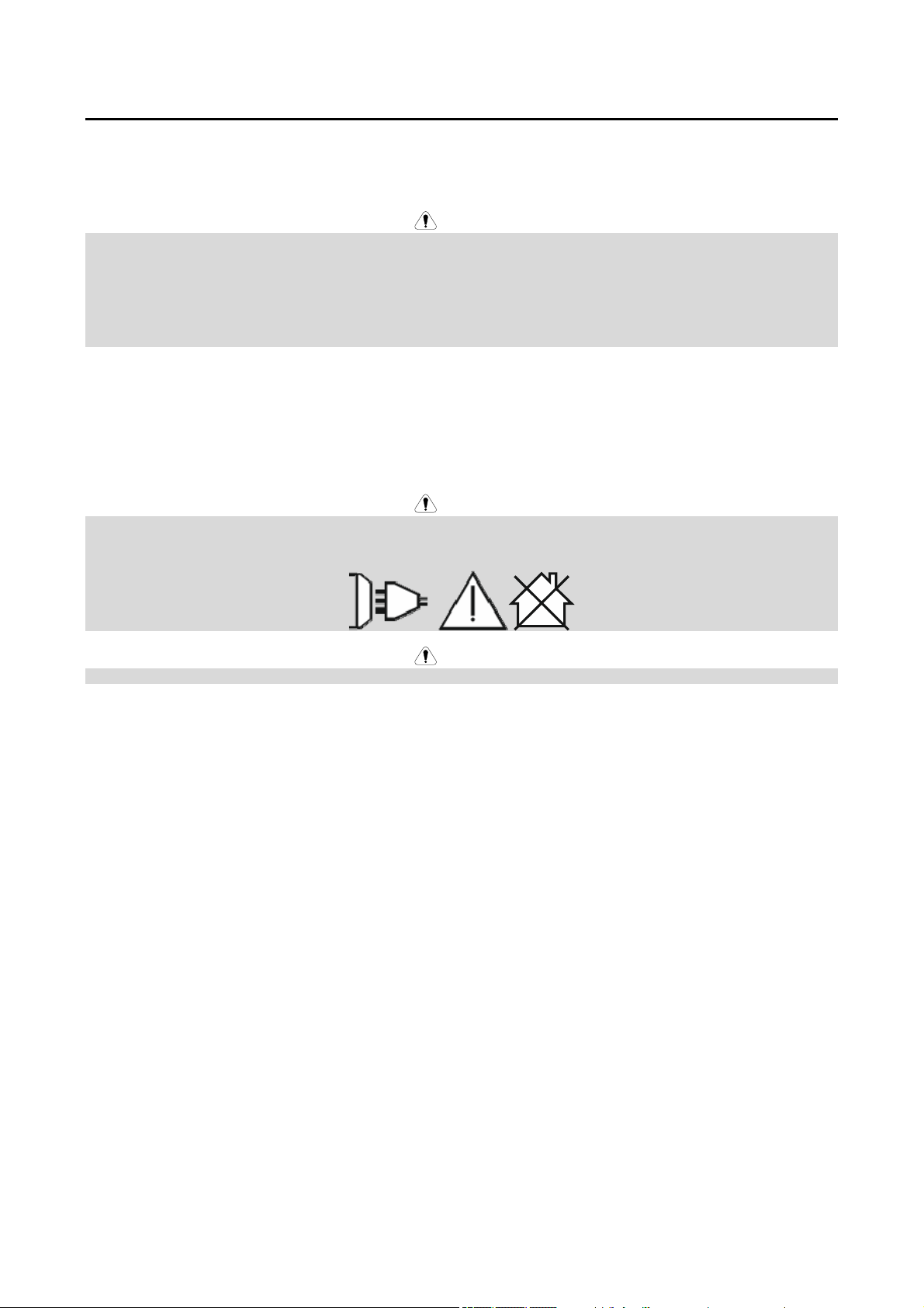
WARNING
Provided that the public low voltage system impedance at the point of common coupling is lower than:
56,4 mΩ for the POWERTEC i380C ADVANCED;
23 mΩ for the POWERTEC i450C ADVANCED.
This equipment is compliant with IEC 61000-3-11 and IEC-3-12 and can be connected to public low voltage systems. It is
the responsibility of the installer or user of the equipment to ensure, by consultation with the distribution network operator if
necessary, that the system impedance complies with the impedance restrictions.
Consider the following guidelines to reduce electromagnetic emissions from the machine.
Connect the machine to the input supply according to this manual. If disturbances occur if may be necessary to take
additional precautions such as filtering the input supply.
The output cables should be kept as short as possible and should be positioned together. If possible connect the
work piece to ground in order to reduce the electromagnetic emissions. The operator must check that connecting the
work piece to ground does not cause problems or unsafe operating conditions for personnel and equipment.
Shielding of cables in the work area can reduce electromagnetic emissions. This may be necessary for special
applications.
WARNING
The Class A equipment is not intended for use in residential locations where the electrical power is provided by the public
low-voltage supply system. There may be potential difficulties in ensuring electromagnetic compatibility in those locations,
due to conducted as well as radiated disturbances.
11/04
WARNING
While a high electromagnetic field occurs, a welding current can fluctuate.
English 3 English
Safety
01/11
WARNING
This equipment must be used by qualified personnel. Be sure that all installation, operation, maintenance and repair
procedures are performed only by qualified person. Read and understand this manual before operating this equipment.
Failure to follow the instructions in this manual could cause serious personal injury, loss of life, or damage to this equipment.
Read and understand the following explanations of the warning symbols. Lincoln Electric is not responsible for damages
caused by improper installation, improper care or abnormal operation.
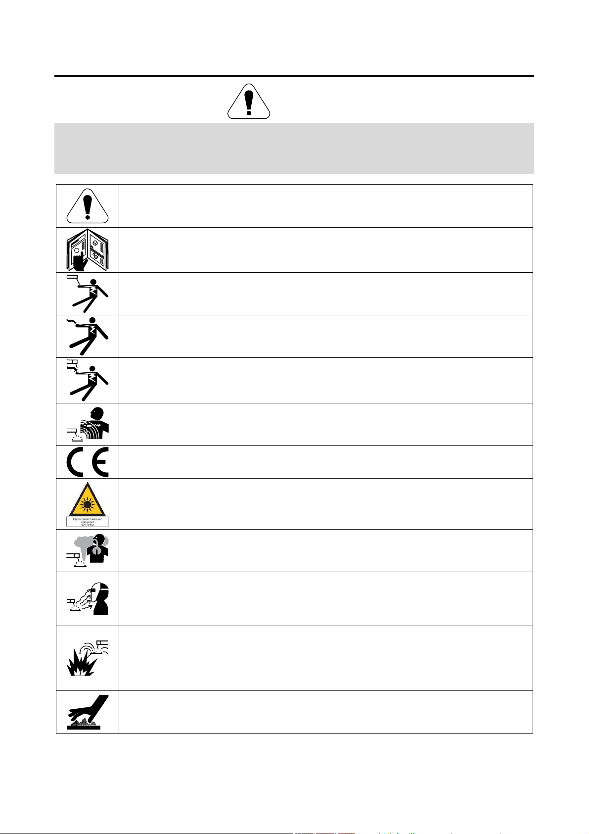
WARNING: This symbol indicates that instructions must be followed to avoid serious personal injury,
loss of life, or damage to this equipment. Protect yourself and others from possible serious injury or
death.
READ AND UNDERSTAND INSTRUCTIONS: Read and understand this manual before operating
this equipment. Arc welding can be hazardous. Failure to follow the instructions in this manual could
cause serious personal injury, loss of life, or damage to this equipment.
ELECTRIC SHOCK CAN KILL: Welding equipment generates high voltages. Do not touch the
electrode, work clamp, or connected work pieces when this equipment is on. Insulate yourself from
the electrode, work clamp, and connected work pieces.
ELECTRICALLY POWERED EQUIPMENT: Turn off input power using the disconnect switch at the
fuse box before working on this equipment. Ground this equipment in accordance with local electrical
regulations.
ELECTRICALLY POWERED EQUIPMENT: Regularly inspect the input, electrode, and work clamp
cables. If any insulation damage exists replace the cable immediately. Do not place the electrode
holder directly on the welding table or any other surface in contact with the work clamp to avoid the
risk of accidental arc ignition.
ELECTRIC AND MAGNETIC FIELDS MAY BE DANGEROUS: Electric current flowing through any
conductor creates electric and magnetic fields (EMF). EMF fields may interfere with some
pacemakers, and welders having a pacemaker shall consult their physician before operating this
equipment.
CE COMPLIANCE: This equipment complies with the European Community Directives.
ARTIFICIAL OPTICAL RADIATION: According with the requirements in 2006/25/EC Directive and
EN 12198 Standard, the equipment is a category 2. It makes mandatory the adoption of Personal
Protective Equipments (PPE) having filter with a protection degree up to a maximum of 15, as
required by EN169 Standard.
FUMES AND GASES CAN BE DANGEROUS: Welding may produce fumes and gases hazardous to
health. Avoid breathing these fumes and gases. To avoid these dangers the operator must use
enough ventilation or exhaust to keep fumes and gases away from the breathing zone.
ARC RAYS CAN BURN: Use a shield with the proper filter and cover plates to protect your eyes from
sparks and the rays of the arc when welding or observing. Use suitable clothing made from durable
flame-resistant material to protect you skin and that of your helpers. Protect other nearby personnel
with suitable, non-flammable screening and warn them not to watch the arc nor expose themselves to
the arc.
WELDING SPARKS CAN CAUSE FIRE OR EXPLOSION: Remove fire hazards from the welding
area and have a fire extinguisher readily available. Welding sparks and hot materials from the welding
process can easily go through small cracks and openings to adjacent areas. Do not weld on any
tanks, drums, containers, or material until the proper steps have been taken to insure that no
flammable or toxic vapors will be present. Never operate this equipment when flammable gases,
vapors or liquid combustibles are present.
WELDED MATERIALS CAN BURN: Welding generates a large amount of heat. Hot surfaces and
materials in work area can cause serious burns. Use gloves and pliers when touching or moving
materials in the work area.
English 4 English

CYLINDER MAY EXPLODE IF DAMAGED: Use only compressed gas cylinders containing the
correct shielding gas for the process used and properly operating regulators designed for the gas and
pressure used. Always keep cylinders in an upright position securely chained to a fixed support. Do
not move or transport gas cylinders with the protection cap removed. Do not allow the electrode,
electrode holder, work clamp or any other electrically live part to touch a gas cylinder. Gas cylinders
must be located away from areas where they may be subjected to physical damage or the welding
process including sparks and heat sources.
MOVING PARTS ARE DANGEROUS: There are moving mechanical parts in this machine, which can
cause serious injury. Keep your hands, body and clothing away from those parts during machine
starting, operating and servicing.
HOT COOLANT CAN BURN SKIN: Always be sure coolant is NOT HOT before servicing the cooler.
SAFETY MARK: This equipment is suitable for supplying power for welding operations carried out in
an environment with increased hazard of electric shock.
The manufacturer reserves the Right to make changes and/or improvements in design without upgrade at the same time
the operator’s manual.
English 5 English
Introduction
General Description
The welding machines POWERTEC i380C ADVANCED
and POWERTEC i450C ADVANCED enables welding:
GMAW (MIG/MAG),
FCAW (Flux-Cored),
SMAW (MMA),
The following equipment has been added to
POWERTEC i380C ADVANCED and
POWERTEC i450C ADVANCED:
Work lead – 3m,
Gas hose – 2m,
Driving roll V1.0/V1.2 for solid wire (mounted in the
wire feeder).
Recommended equipment, which can be bought by
user, was mentioned in the chapter "Accessories".
Installation and Operator Instructions
Read this entire section before installation or operation
of the machine.
Location and Environment
This machine will operate in harsh environments.
However, it is important that simple preventative
measures are followed to assure long life and reliable
operation.
Do not place or operate this machine on a surface
with an incline greater than 15° from horizontal.
Do not use this machine for pipe thawing.
This machine must be located where there is free
circulation of clean air without restrictions for air
movement to and from the air vents. Do not cover
the machine with paper, cloth or rags when switched
on.
Dirt and dust that can be drawn into the machine
should be kept to a minimum.
This machine has a protection rating of IP23. Keep it
dry when possible and do not place it on wet ground
or in puddles.
Locate the machine away from radio controlled
machinery. Normal operation may adversely affect
the operation of nearby radio controlled machinery,
which may result in injury or equipment damage.
Read the section on electromagnetic compatibility in
this manual.
Do not operate in areas with an ambient temperature
greater than 40°C.
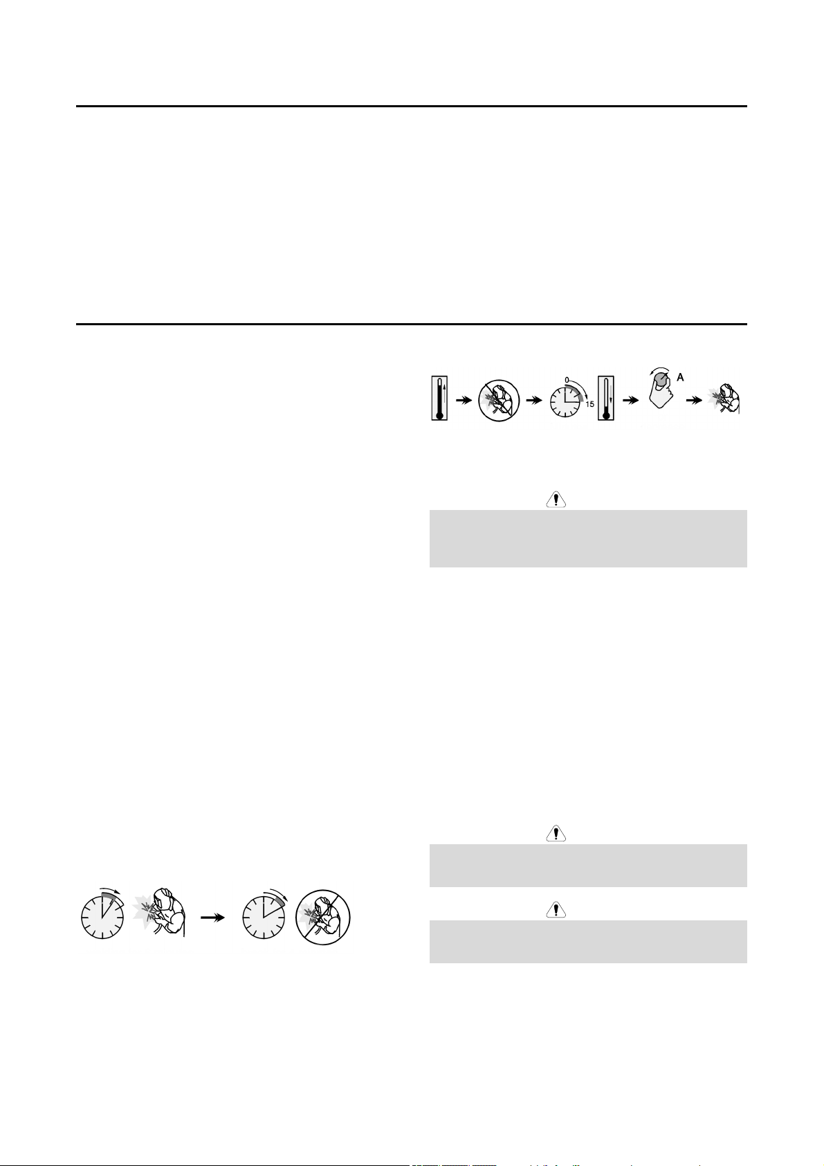
Duty cycle and Overheating
The duty cycle of a welding machine is the percentage of
time in a 10 minute cycle at which the welder can
operate the machine at rated welding current.
Example: 60% duty cycle
Welding for 6 minutes. Break for 4 minutes.
Excessive extension of the duty cycle will cause the
thermal protection circuit to activate.
Minutes or decrease
Input Supply Connection
Only a qualified electrician can connect the welding
machine to the supply network. Installation had to be
made in accordance with the appropriate National
Electrical Code and local regulations.
Check the input voltage, phase and frequency supplied to
this machine before turning it on. Verify the connection of
ground wires from the machine to the input source. The
welding machine POWERTEC i380C ADVANCED,
POWERTEC i4500C ADVANCED must be connected to
a correctly installed plug-in socket with an earth pin.
Input voltage is 400 Vac 50/60Hz. For more information
about input supply refer to the technical specification
section of this manual and to the rating plate of the
machine.
Make sure that the amount of mains power available
from the input supply is adequate for normal operation of
the machine. The necessary delayed fuse or circuit
breaker and cable sizes are indicated in the technical
specification section of this manual.
The welding machine can be supplied from a power
generator of output power at least 30% larger than input
power of the welding machine.
When powering the machine from a generator be sure to
turn off welder first, before generator is shut down, in
order to prevent damage to welder!
Output Connections
Refer to points [3], [4] and [6] of the Figures below.
Duty Cycle
WARNING
WARNING
WARNING
English 6 English
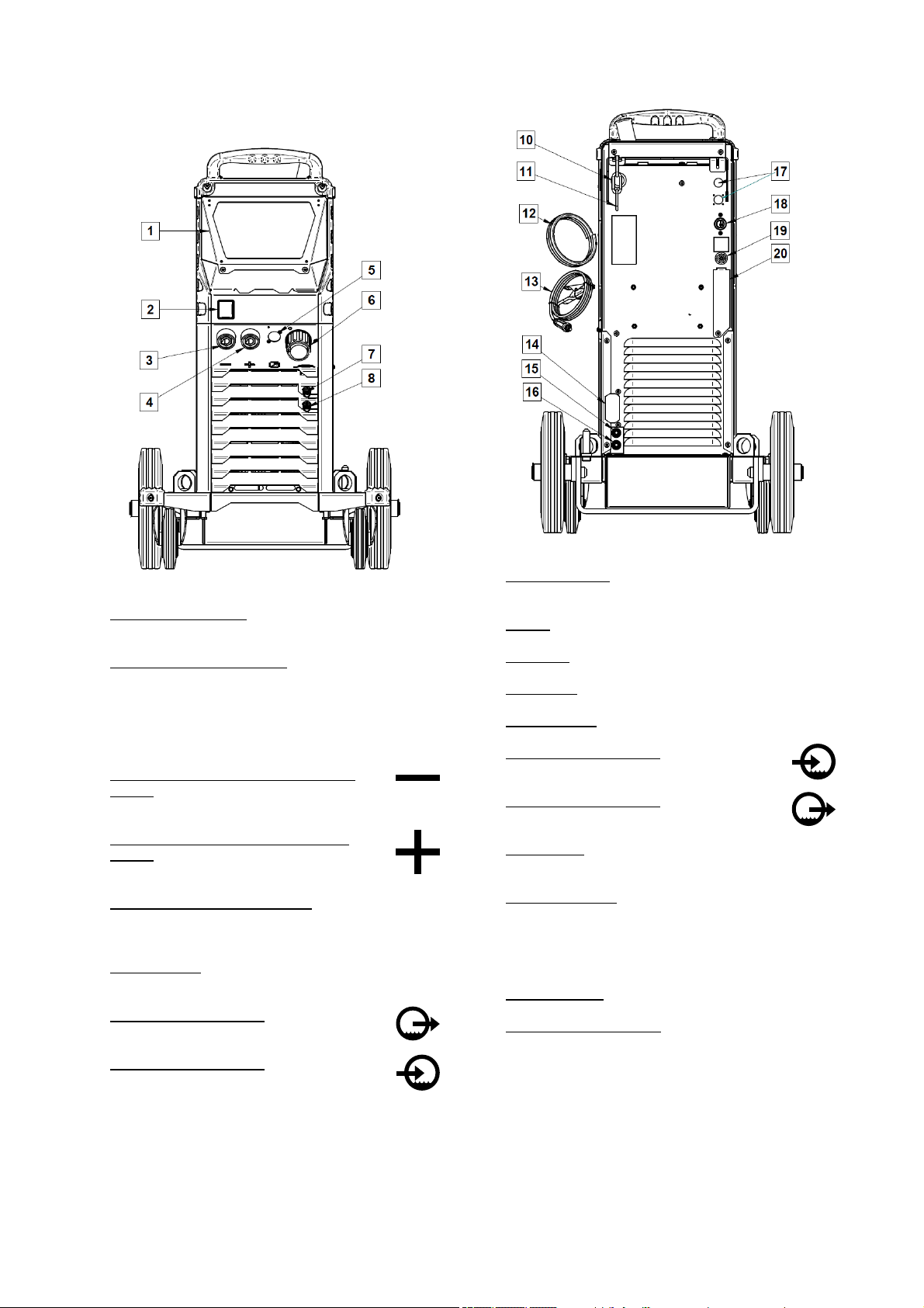
Controls and Operational Features
Front Panel
Rear panel
Figure 1.
1. User Interface Cover. Cover shielding user interface.
U7 User Interface is described in separate chapter.
2. Power Switch ON/OFF (I/O): Controls the input
power to the machine. Be sure the power source is
connected to the mains supply before turning power
on ("I"). After input power is connected and the
power switch is turned on, the indicator will light up to
indicate the machine is ready to weld.
3. Negative Output Socket for the Welding
Circuit: For connecting an electrode holder
with lead / work lead.
4. Positive Output Socket for the Welding
Circuit: For connecting an electrode holder
with lead / work lead.
5. Remote Control Connector Plug: To install Remote
Control Kit. This connector allows connection
Remote Control. See "Accessories" chapter.
6. EURO Socket: For connecting a welding gun (for
GMAW / FCAW process).
7. Quick Connect Coupling: Coolant outlet
(supplies cool coolant to the torch/gun).
8. Quick Connect Coupling: Coolant inlet
(takes warm coolant from torch/gun).
Figure 2.
10. Wire Liner Entry: Enables installing liner for welding
wire delivered in drum package.
11. Chain: To protect gas bottle.
12. Gas hose.
13. Work Lead.
14. Cover bracket: To install cooler cable holder bracket.
15. Quick Connect Coupling: Coolant inlet
(supplies cool coolant to the torch/gun).
16. Quick Connect Coupling: Coolant outlet
(takes warm coolant from torch/gun).
17. Supply Plug: For CO2 gas heater kit (see
“Accessories” chapter).
18. Power Lead (5m): Connect the supply plug to the
existing input cable that is rated for the machine as
indicated in this manual, and conforms to all
applicable standards. This connection shall be
performed by a qualified person only.
19. Gas Connector: Connection for gas line.
20. Gas Flow Regulator Plug: Gas flow regulator can be
purchased separately (see “Accessories” chapter).
English 7 English

Internal Controls
Figure 3.
21. Cold Inch/ Gas Purge Switch: This switch enables
wire feeding or gas flow without turning on output
voltage.
22. USB Receptacle Type A: For USB memory stick
connection. For machine software update and
service purpose.
23. Spooled Wire (for GMAW / FCAW): The machine
does not include a spooled wire.
24. Fuse F1: Use the 2A/400V (6,3x32mm) low blow
fuse
25. Wire drive feeding system: 4-Roll wire drive
mechanisms with quick-change feed rolls.
26. Terminal Block of Changing Polarity Plug (for GMAW
/ FCAW-SS process): This terminal block enables to
set the welding polarity (+ ; -), which will be given at
the welding gun
27. Wire Spool Support: Maximum 16kg spools. Accepts
plastic, steel and fiber spools onto 51 mm spindle.
Note: Plastic Brake Nut has a Left-hand thread.
English 8 English
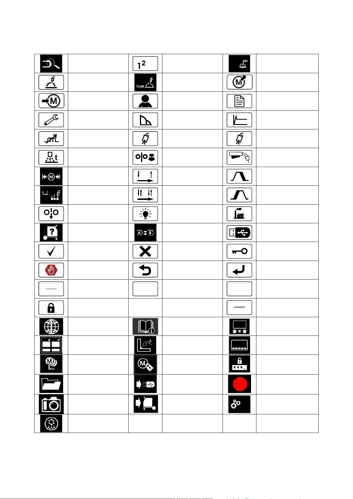
Guide’s Marking Interface
n
A
Table 1. Symbols description
Select Welding Process
GMAW Process
(MIG/MAG)
Save to the User
Memory
.
.
.
3
Select Welding Program
FCAW Process
User Setup
SMAW Process
(MMA)
Recall from the User
Memory
Advanced Setup
mi
in
Configuration
Pinch
t1
Burnback Time
Memory Limits
Spot Welding Settings
Cold Feed
View Software and
Hardware Version
Information
Check Mark
Error
Wire Feed Speed
in [in/min]
V
Locked
Arc Force
Preflow Time
Run-in WFS
2-Step
4-Step
Brightness Level
A/B Procedure
Resignation Mark
ESCape Button
Welding Voltage
A
m
min
Hot Start
Postflow Time
t2
Select Function of Gun
Trigger (2-Step / 4-Step)
Crater Procedure
Start Procedure
Restore Factory Setting
USB Memory
Access control
Confirm Button
Welding Current
Wire Feed Speed
in [m/min]
Set the Language
Standard UI look
Enable/ Disable Jobs
Mode or Select Jobs for
Jobs Mode
Weld History
SnapShot
Support
Advanced UI look
Enable/ Disable Jobs
Save
Save
Load
Display Configuration
Settings
Select Item
Lock
Service weld logs
Service Menu
Cooler
User Interface Advanced (U7)
English 9 English
 Loading...