

Lincoln Electric POWERTEC 161C, POWERTEC 271C, POWERTEC 231C, POWERTEC 191C Operator's Manual
POWERTEC
161C, 191C, 231C & 271C
OPERATOR’S MANUAL
MANUALE OPERATIVO
BEDIENUNGSANLEITUNG
MANUAL DE INSTRUCCIONES
MANUEL D'UTILISATION
BRUKSANVISNING OG DELELISTE
GEBRUIKSAANWIJZING
BRUKSANVISNING
IM3015
09/2008
Rev. 3
INSTRUKCJA OBSŁUGI
KÄYTTÖOHJE
LINCOLN ELECTRIC BESTER S.A.
ul. Jana III Sobieskiego 19A, 58-260 Bielawa, Poland
www.lincolnelectric.eu

Declaration of conformity
Dichiarazione di conformità
Konformitätserklärung
Declaración de conformidad
Déclaration de conformité
Samsvars erklæring
Verklaring van overeenstemming
LINCOLN ELECTRIC BESTER S.A.
Försäkran om överensstämmelse
Deklaracja zgodności
Vakuutus yhteensopivuudesta
Declares that the welding machine:
Dichiara che Il generatore per saldatura tipo:
Erklärt, daß die Bauart der Maschine:
Declara que el equipo de soldadura:
Déclare que le poste de soudage:
Bekrefter at denne sveisemaskin:
Verklaart dat de volgende lasmachine:
POWERTEC 161C
conforms to the following directives:
è conforme alle seguenti direttive:
den folgenden Bestimmungen entspricht:
es conforme con las siguientes directivas:
est conforme aux directives suivantes:
er i samsvar med følgende direktiver:
overeenkomt conform de volgende richtlijnen:
73/23/CEE, 89/336/CEE
and has been designed in compliance with the following
standards:
ed è stato progettato in conformità alle seguenti norme:
und in Übereinstimmung mit den nachstehenden normen
hergestellt wurde:
y ha sido diseñado de acuerdo con las siguientes
normas:
et qu'il a été conçu en conformité avec les normes:
og er produsert og testet iht. følgende standarder:
Försäkrar att svetsomriktaren:
Deklaruje, że spawalnicze źródło energii:
Vakuuttaa, että hitsauskone:
överensstämmer med följande direktiv:
spełnia następujące wytyczne:
täyttää seuraavat direktiivit:
en is ontworpen conform de volgende normen:
och att den konstruerats i överensstämmelse med
följande standarder:
i że zostało zaprojektowane zgodnie z wymaganiami
następujących norm:
ja on suunniteltu seuraavien standardien mukaan:
EN 60974-1, EN 60974-10
(2007)
Paweł Lipiński
Operations Director
LINCOLN ELECTRIC BESTER S.A., ul. Jana III Sobieskiego 19A, 58-260 Bielawa, Poland
II
12/05

Declaration of conformity
Dichiarazione di conformità
Konformitätserklärung
Declaración de conformidad
Déclaration de conformité
Samsvars erklæring
Verklaring van overeenstemming
LINCOLN ELECTRIC BESTER S.A.
Försäkran om överensstämmelse
Deklaracja zgodności
Vakuutus yhteensopivuudesta
Declares that the welding machine:
Dichiara che Il generatore per saldatura tipo:
Erklärt, daß die Bauart der Maschine:
Declara que el equipo de soldadura:
Déclare que le poste de soudage:
Bekrefter at denne sveisemaskin:
Verklaart dat de volgende lasmachine:
POWERTEC 191C, 231C & 271C
conforms to the following directives:
è conforme alle seguenti direttive:
den folgenden Bestimmungen entspricht:
es conforme con las siguientes directivas:
est conforme aux directives suivantes:
er i samsvar med følgende direktiver:
overeenkomt conform de volgende richtlijnen:
73/23/CEE, 89/336/CEE
and has been designed in compliance with the following
standards:
ed è stato progettato in conformità alle seguenti norme:
und in Übereinstimmung mit den nachstehenden normen
hergestellt wurde:
y ha sido diseñado de acuerdo con las siguientes
normas:
et qu'il a été conçu en conformité avec les normes:
og er produsert og testet iht. følgende standarder:
Försäkrar att svetsomriktaren:
Deklaruje, że spawalnicze źródło energii:
Vakuuttaa, että hitsauskone:
överensstämmer med följande direktiv:
spełnia następujące wytyczne:
täyttää seuraavat direktiivit:
en is ontworpen conform de volgende normen:
och att den konstruerats i överensstämmelse med
följande standarder:
i że zostało zaprojektowane zgodnie z wymaganiami
następujących norm:
ja on suunniteltu seuraavien standardien mukaan:
EN 60974-1, EN 60974-10
(2008)
Paweł Lipiński
Operations Director
LINCOLN ELECTRIC BESTER S.A., ul. Jana III Sobieskiego 19A, 58-260 Bielawa, Poland
III
12/05
English
Italiano
Deutsch
Español
Français
Norsk
Nederlandse
Svenska
Polski
Suomi
Do not dispose of electrical equipment together with normal waste!
07/06
In observance of European Directive 2002/96/EC on Waste Electrical and Electronic Equipment (WEEE) and its
implementation in accordance with national law, electrical equipment that has reached the end of its life must be
collected separately and returned to an environmentally compatible recycling facility. As the owner of the
equipment, you should get information on approved collection systems from our local representative.
By applying this European Directive you will protect the environment and human health!
Non gettare le apparecchiature elettriche tra i rifiuti domestici!
In ottemperanza alla Direttiva Europea 2002/96/CE sui Rifiuti di Apparechiature Elettriche ed Elettroniche (RAEE)
e la sua attuazione in conformità alle norme nazionali, le apparecchiature elettriche esauste devono essere
raccolte separatamente e restituite ad una organizzazione di riciclaggio ecocompatibile. Come proprietario
dell’apparecchiatura, Lei potrà ricevere informazioni circa il sistema approvato di raccolta, dal nostro
rappresentante locale.
Applicando questa Direttiva Europea Lei contribuirà a migliorare l’ambiente e la salute!
Werfen Sie Elektrowerkzeuge nicht in den Hausmüll!
Gemäss Europäischer Richtlinie 2002/96/EG über Elektro- und Elektronik- Altgeräte (Waste Electrical and
Electronic Equipment, WEEE) und Umsetzung in nationales Recht müssen verbrauchte Elektrowerkzeuge
getrennt gesammelt und einer umweltgerechten Wiederverwertung zugeführt werden. Als Eigentümer diese
Werkzeuges sollten sie sich Informationen über ein lokales autorisiertes Sammel- bzw. Entsorgungssystem
einholen.
Mit der Anwendung dieser EU Direktive tragen sie wesentlich zur Schonung der Umwelt und ihrer Gesundheit bei!
No tirar nunca los aparatos eléctricos junto con los residuos en general!.
De conformidad a la Directiva Europea 2002/96/EC relativa a los Residuos de Equipos Eléctricos o Electrónicos
(RAEE) y al acuerdo de la legislación nacional, los equipos eléctricos deberán ser recogidos y reciclados
respetando el medioambiente. Como propietario del equipo, deberá informar de los sistemas y lugares
apropiados para la recogida de los mismos.
Aplicar esta Directiva Europea protegerá el medioambiente y su salud!
Ne pas jeter les appareils électriques avec les déchets ordinaires!
Conformément à la Directive Européenne 2002/96/EC relative aux Déchets d' Équipements Électriques ou
Électroniques (DEEE), et à sa transposition dans la législation nationale, les appareils électriques doivent être
collectés à part et être soumis à un recyclage respectueux de l’environnement. En tant que propriétaire de
l’équipement, vous devriez vous informer sur les systèmes de collecte approuvés auprès nos représentants
locaux.
Appliquer cette Directive Européenne améliorera l’environnement et la santé!
Kast ikke elektriske artikler sammen med vanlig søppel.
I følge det europeiske direktivet for Elektronisk Søppel og Elektriske Artikler 2002/96/EC (Waste Electrical and
Electronic Equipment, WEEE) skal alt avfall kildesorteres og leveres på godkjente plasser i følge loven.
Godkjente retur plasser gis av lokale myndigheter.
Ved å følge det europeiske direktivet bidrar du til å bevare naturen og den menskelige helse.
Gooi elektrische apparatuur nooit bij gewoon afval!
Met inachtneming van de Europese Richtlijn 2002/96/EC met betrekking tot Afval van Elektrische en
Elektronische Apparatuur (Waste Electrical and Electronic Equipment, WEEE) en de uitvoering daarvan in
overeenstemming met nationaal recht, moet elektrische apparatuur, waarvan de levensduur ten einde loopt, apart
worden verzameld en worden ingeleverd bij een recycling bedrijf, dat overeenkomstig de milieuwetgeving
opereert. Als eigenaar van de apparatuur moet u informatie inwinnen over goedgekeurde verzamelsystemen van
onze vertegenwoordiger ter plaatse.
Door het toepassen van deze Europese Richtlijn beschermt u het milieu en ieders gezondheid!
Släng inte uttjänt elektrisk utrustning tillsammans med annat avfall!
Enligt Europadirektiv 2002/96/EC ang. Uttjänt Elektrisk och Elektronisk Utrustning (Waste Electrical and
Electronic Equipment, WEEE) och dess implementering enligt nationella lagar, ska elektrisk utrustning som tjänat
ut sorteras separat och lämnas till en miljögodkänd återvinningsstation. Som ägare till utrustningen, bör du skaffa
information om godkända återvinningssystem från dina lokala myndigheter.
Genom att följa detta Europadirektiv bidrar du till att skydda miljö och hälsa!
Nie wyrzucać osprzętu elektrycznego razem z normalnymi odpadami!
Zgodnie z Dyrektywą Europejską 2002/96/EC dotyczącą Pozbywania się zużytego Sprzętu Elektrycznego i
Elektronicznego (Waste Electrical and Electronic Equipment, WEEE) i jej wprowadzeniem w życie zgodnie z
międzynarodowym prawem, zużyty sprzęt elektryczny musi być składowany oddzielnie i specjalnie utylizowany.
Jako właściciel urządzeń powinieneś otrzymać informacje o zatwierdzonym systemie składowania od naszego
lokalnego przedstawiciela.
Stosując te wytyczne bedziesz chronił środowisko i zdrowie człowieka!
Älä hävitä sähkölaitteita sekajätteiden mukana!
Noudatettaessa Euroopan Unionin Direktiiviä 2002/96/EY Sähkölaite- ja Elektroniikkajätteestä ( WEEE ) ja
toteutettaessa sitä sopusoinnussa kansallisen lain kanssa, sähkölaite, joka on tullut elinkaarensa päähän pitää
kerätä erilleen ja toimittaa sähkö- ja elektroniikkaromujen keräyspisteeseen. Lisätietoja tämän tuotteen
käsittelystä, keräämisestä ja kierrätyksestä saa kunnan ympäristöviranomaisilta.
Noudattamalla tätä Euroopan Unionin direktiiviä, autat torjumaan kielteiset ynpäristö- ja terveysvaikutukset!
IV

THANKS! For having choosen the QUALITY of the Lincoln Electric products.
12/05
• Please Examine Package and Equipment for Damage. Claims for material damaged in shipment must be notified
immediately to the dealer.
• For future reference record in the table below your equipment identification information. Model Name, Code & Serial
Number can be found on the machine rating plate.
GRAZIE! Per aver scelto la QUALITÀ dei prodotti Lincoln Electric.
• Esamini Imballo ed Equipaggiamento per rilevare eventuali danneggiamenti. Le richieste per materiali danneggiati dal
trasporto devono essere immediatamente notificate al rivenditore.
• Per ogni futuro riferimento, compilare la tabella sottostante con le informazioni di identificazione equipaggiamento.
Modello, Codice (Code) e Matricola (Serial Number) sono reperibili sulla targa dati della macchina.
VIELEN DANK! Dass Sie sich für ein QUALITÄTSPRODUKT von Lincoln Electric entschieden haben.
• Bitte überprüfen Sie die Verpackung und den Inhalt auf Beschädigungen. Transportschäden müssen sofort dem Händler
gemeldet werden.
• Damit Sie Ihre Gerätedaten im Bedarfsfall schnell zur Hand haben, tragen Sie diese in die untenstehende Tabelle ein.
Typenbezeichnung, Code- und Seriennummer finden Sie auf dem Typenschild Ihres Gerätes.
GRACIAS! Por haber escogido los productos de CALIDAD Lincoln Electric.
• Por favor, examine que el embalaje y el equipo no tengan daños. La reclamación del material dañado en el transporte
debe ser notificada inmediatamente al proveedor.
• Para un futuro, a continuación encontrará la información que identifica a su equipo. Modelo, Code y Número de Serie los
cuales pueden ser localizados en la placa de características de su equipo.
MERCI! Pour avoir choisi la QUALITÉ Lincoln Electric.
• Vérifiez que ni l’équipement ni son emballage ne sont endommagés. Toute réclamation pour matériel endommagé doit
être immédiatement notifiée à votre revendeur.
• Notez ci-dessous toutes les informations nécessaires à l’identification de votre équipement. Le nom du Modèle ainsi que
les numéros de Code et Série figurent sur la plaque signalétique de la machine.
TAKK! For at du har valgt et KVALITETSPRODUKT fra Lincoln Electric.
• Kontroller emballsjen og produktet for feil eller skader. Eventuelle feil eller transportskader må umiddelbart rapporteres
dit du har kjøpt din maskin.
• For fremtidig referanse og for garantier og service, fyll ut den tekniske informasjonen nedenfor i dette avsnittet. Modell
navn, Kode & Serie nummer finner du på den tekniske platen på maskinen.
BEDANKT! Dat u gekozen heeft voor de KWALITEITSPRODUCTEN van Lincoln Electric.
• Controleert u de verpakking en apparatuur op beschadiging. Claims over transportschade moeten direct aan de dealer of
aan Lincoln electric gemeld worden.
• Voor referentie in de toekomst is het verstandig hieronder u machinegegevens over te nemen. Model Naam, Code &
Serienummer staan op het typeplaatje van de machine.
TACK! För att ni har valt en KVALITETSPRODUKT från Lincoln Electric.
• Vänligen kontrollera förpackning och utrustning m.a.p. skador. Transportskador måste omedelbart anmälas till
återförsäljaren eller transportören.
• Notera informationen om er utrustnings identitet i tabellen nedan. Modellbeteckning, code- och serienummer hittar ni på
maskinens märkplåt.
DZIĘKUJEMY! Za docenienie JASKOŚCI produktów Lincoln Electric.
• Proszę sprawdzić czy opakownie i sprzęt nie są uszkodzone. Reklamacje uszkodzeń powstałych podczas transportu
muszą być natychmiast zgłoszone do dostawcy (dystrybutora).
• Dla ułatwienia prosimy o zapisanie na tej stronie danych identyfikacyjnych wyrobów. Nazwa modelu, Kod i Numer
Seryjny, które możecie Państwo znaleźć na tabliczce znamionowej wyrobu.
KIITOS! Kiitos, että olet valinnut Lincoln Electric LAATU tuotteita.
• Tarkista pakkaus ja tuotteet vaurioiden varalta. Vaateet mahdollisista kuljetusvaurioista on ilmoitettava välittömästi
jälleenmyyjälle.
• Tulevaisuutta varten täytä alla oleva lomake laitteen tunnistusta varten. Mallin, Koodin ja Sarjanumeron voit löytää
konekilvestä.
Model Name, Modello, Typenbezeichnung, Modelo, Nom du modèle, Modell navn, Model Naam, Modellbeteckning, Nazwa
modelu, Mallinimi:
………………...…………………………….…………………………………………………………………………………………..
Code & Serial number, Code (codice) e Matricola, Code- und Seriennummer, Code y Número de Serie, Numéros de Code et
Série, Kode & Serie nummer, Code en Serienummer, Code- och Serienummer, Kod i numer Seryjny, Koodi ja Sarjanumero:
………………….……………………………………………….. …………………………………………………….……………..
Date & Where Purchased, Data e Luogo d’acquisto, Kaufdatum und Händler, Fecha y Nombre del Proveedor, Lieu et Date
d’acquisition, Kjøps dato og Sted, Datum en Plaats eerste aankoop, Inköpsdatum och Inköpsställe, Data i Miejsce zakupu,
Päiväys ja Ostopaikka:
…………………………………………………………………... ……………………….…………………………………………..
V

ENGLISH INDEX
Safety.................................................................................................................................................................................................... A-1
Installation and Operator Instructions ................................................................................................................................................... A-2
Electromagnetic Compatibility (EMC) ................................................................................................................................................... A-5
Technical Specifications ....................................................................................................................................................................... A-6
INDICE ITALIANO
Sicurezza .............................................................................................................................................................................................. B-1
Installazione e Istruzioni Operative....................................................................................................................................................... B-2
Compatibilità Elettromagnetica (EMC).................................................................................................................................................. B-6
Specifiche Tecniche.............................................................................................................................................................................. B-7
INHALTSVERZEICHNIS DEUTSCH
Sicherheitsmaßnahmen / Unfallschutz ................................................................................................................................................. C-1
Installation und Bedienungshinweise.................................................................................................................................................... C-2
Elektromagnetische Verträglichkeit (EMC) ........................................................................................................................................... C-6
Technische Daten.................................................................................................................................................................................C-7
INDICE ESPAÑOL
Seguridad.............................................................................................................................................................................................. D-1
Instalación e Instrucciones de Funcionamiento....................................................................................................................................D-2
Compatibilidad Electromagnética (EMC)..............................................................................................................................................D-6
Especificaciones Técnicas.................................................................................................................................................................... D-7
INDEX FRANÇAIS
Sécurité................................................................................................................................................................................................. E-1
Installation et Instructions d'Utilisation.................................................................................................................................................. E-2
Compatibilité Electromagnétique (CEM)............................................................................................................................................... E-6
Caractéristiques Techniques ................................................................................................................................................................E-7
NORSK INNHOLDSFORTEGNELSE
Sikkerhetsregler.....................................................................................................................................................................................F-1
Installasjon og Brukerinstruksjon ...........................................................................................................................................................F-2
Elektromagnetisk Kompatibilitet (EMC) .................................................................................................................................................F-6
Tekniske Spesifikasjoner .......................................................................................................................................................................F-7
NEDERLANDSE INDEX
Veiligheid ..............................................................................................................................................................................................G-1
Installatie en Bediening.........................................................................................................................................................................G-2
Elektromagnetische Compatibiliteit (EMC) ...........................................................................................................................................G-6
Technische Specificaties ......................................................................................................................................................................G-7
SVENSK INNEHÅLLSFÖRTECKNING
Säkerhetsanvisningar ........................................................................................................................................................................... H-1
Instruktioner för Installation och Handhavande .................................................................................................................................... H-2
Elektromagnetisk Kompatibilitet (EMC) ................................................................................................................................................ H-5
Tekniska Specifikationer.......................................................................................................................................................................H-6
SKOROWIDZ POLSKI
Bezpieczeństwo Użytkowania ................................................................................................................................................................I-1
Instrukcja Instalacji i Eksploatacji ...........................................................................................................................................................I-2
Kompatybilność Elektromagnetyczna (EMC) .........................................................................................................................................I-6
Dane Techniczne....................................................................................................................................................................................I-7
SISÄLLYSLUETTELO
Turvallisuus............................................................................................................................................................................................J-1
Asennus ja Käyttöohjeet ........................................................................................................................................................................J-2
Elektromagneettinen Yhteensopivuus (EMC)........................................................................................................................................J-5
Tekniset Tiedot ......................................................................................................................................................................................J-6
Spare Parts, Parti di Ricambio, Ersatzteile, Lista de Piezas de Recambio, Pièces de Rechange, Deleliste, Reserve Onderdelen,
Reservdelar, Wykaz Części Zamiennych, Varaosaluettelo ......................................................................................................................1
Electrical Schematic, Schema Elettrico, Elektrische Schaltpläne, Esquema Eléctrico, Schéma Electrique, Elektrisk Skjema, Elektrisch
Schema, Elektriskt Kopplingsschema, Schemat Elektryczny, Sähkökaavio ............................................................................................9
Accessories, Accessori, Zubehör, Accesorios, Accessoires, Tilleggsutstyr, Accessores, Tillbehör, Akcesoria, Varusteet ...................12
WEEE .....................................................................................................................................................................................................14
VI
A
Safety
11/04
WARNING
This equipment must be used by qualified personnel. Be sure that all installation, operation, maintenance and repair
procedures are performed only by qualified person. Read and understand this manual before operating this equipment.
Failure to follow the instructions in this manual could cause serious personal injury, loss of life, or damage to this
equipment. Read and understand the following explanations of the warning symbols. Lincoln Electric is not responsible
for damages caused by improper installation, improper care or abnormal operation.
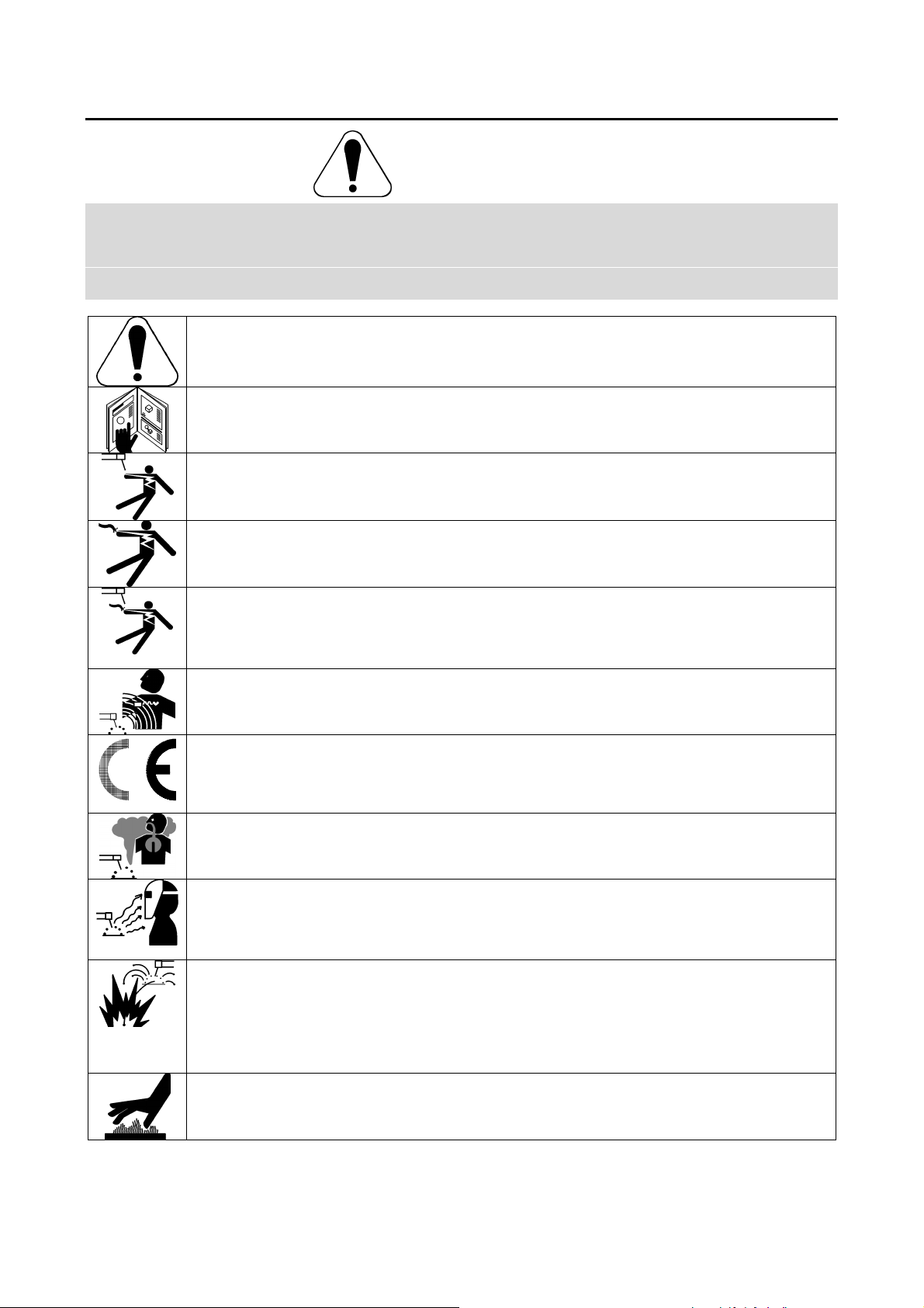
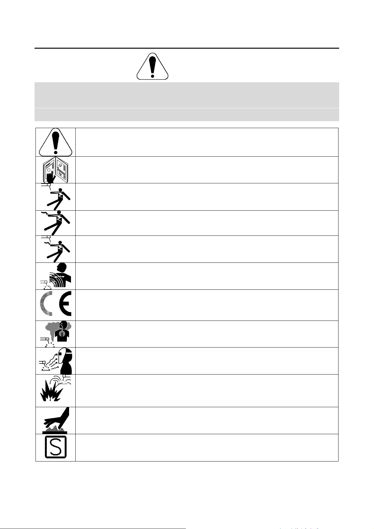
WARNING: This symbol indicates that instructions must be followed to avoid serious personal injury,
loss of life, or damage to this equipment. Protect yourself and others from possible serious injury or
death.
READ AND UNDERSTAND INSTRUCTIONS: Read and understand this manual before operating
this equipment. Arc welding can be hazardous. Failure to follow the instructions in this manual could
cause serious personal injury, loss of life, or damage to this equipment.
ELECTRIC SHOCK CAN KILL: Welding equipment generates high voltages. Do not touch the
electrode, work clamp, or connected work pieces when this equipment is on. Insulate yourself from
the electrode, work clamp, and connected work pieces.
ELECTRICALLY POWERED EQUIPMENT: Turn off input power using the disconnect switch at the
fuse box before working on this equipment. Ground this equipment in accordance with local electrical
regulations.
ELECTRICALLY POWERED EQUIPMENT: Regularly inspect the input, electrode, and work clamp
cables. If any insulation damage exists replace the cable immediately. Do not place the electrode
holder directly on the welding table or any other surface in contact with the work clamp to avoid the
risk of accidental arc ignition.
ELECTRIC AND MAGNETIC FIELDS MAY BE DANGEROUS: Electric current flowing through any
conductor creates electric and magnetic fields (EMF). EMF fields may interfere with some
pacemakers, and welders having a pacemaker shall consult their physician before operating this
equipment.
CE COMPLIANCE: This equipment complies with the European Community Directives.
FUMES AND GASES CAN BE DANGEROUS: Welding may produce fumes and gases hazardous to
health. Avoid breathing these fumes and gases. To avoid these dangers the operator must use
enough ventilation or exhaust to keep fumes and gases away from the breathing zone.
ARC RAYS CAN BURN: Use a shield with the proper filter and cover plates to protect your eyes from
sparks and the rays of the arc when welding or observing. Use suitable clothing made from durable
flame-resistant material to protect you skin and that of your helpers. Protect other nearby personnel
with suitable, non-flammable screening and warn them not to watch the arc nor expose themselves to
the arc.
WELDING SPARKS CAN CAUSE FIRE OR EXPLOSION: Remove fire hazards from the welding
area and have a fire extinguisher readily available. Welding sparks and hot materials from the welding
process can easily go through small cracks and openings to adjacent areas. Do not weld on any
tanks, drums, containers, or material until the proper steps have been taken to insure that no
flammable or toxic vapors will be present. Never operate this equipment when flammable gases,
vapors or liquid combustibles are present.
WELDED MATERIALS CAN BURN: Welding generates a large amount of heat. Hot surfaces and
materials in work area can cause serious burns. Use gloves and pliers when touching or moving
materials in the work area.
SAFETY MARK: This equipment is suitable for supplying power for welding operations carried out in
an environment with increased hazard of electric shock.
-1
A
CYLINDER MAY EXPLODE IF DAMAGED: Use only compressed gas cylinders containing the
correct shielding gas for the process used and properly operating regulators designed for the gas and
pressure used. Always keep cylinders in an upright position securely chained to a fixed support. Do
not move or transport gas cylinders with the protection cap removed. Do not allow the electrode,
electrode holder, work clamp or any other electrically live part to touch a gas cylinder. Gas cylinders
must be located away from areas where they may be subjected to physical damage or the welding
process including sparks and heat sources.
Installation and Operator Instructions
Read this entire section before installation or operation
of the machine.
Location and Environment
This machine will operate in harsh environments.
However, it is important that simple preventative
measures are followed to assure long life and reliable
operation.
• Do not place or operate this machine on a surface
with an incline greater than 15° from horizontal.
• Do not use this machine for pipe thawing.
• This machine must be located where there is free
circulation of clean air without restrictions for air
movement to and from the air vents. Do not cover
the machine with paper, cloth or rags when
switched on.
• Dirt and dust that can be drawn into the machine
should be kept to a minimum.
• This machine has a protection rating of IP23. Keep
it dry when possible and do not place it on wet
ground or in puddles.
• Locate the machine away from radio controlled
machinery. Normal operation may adversely affect
the operation of nearby radio controlled machinery,
which may result in injury or equipment damage.
Read the section on electromagnetic compatibility in
this manual.
• Do not operate in areas with an ambient
temperature greater than 40°C.
Input Supply Connection
Installation and mains outlet socket shall be made and
protected according to appropriate rules.
Check the input voltage, phase, and frequency supplied
to this machine before turning it on. Verify the
connection of grounding wires from the machine to the
input source. The allowable input voltages are 1x230V
50Hz/60Hz. For more information about input supply
refer to the technical specification section of this manual
and to the rating plate of the machine.
Make sure the amount of power available from the input
connection is adequate for normal operation of the
machine. The necessary delayed fuse (or circuit breaker
with ”D” characteristic) and cable sizes are indicated in
the technical specification section of this manual.
Controls and Operational Features
Minutes or decrease
duty cycle
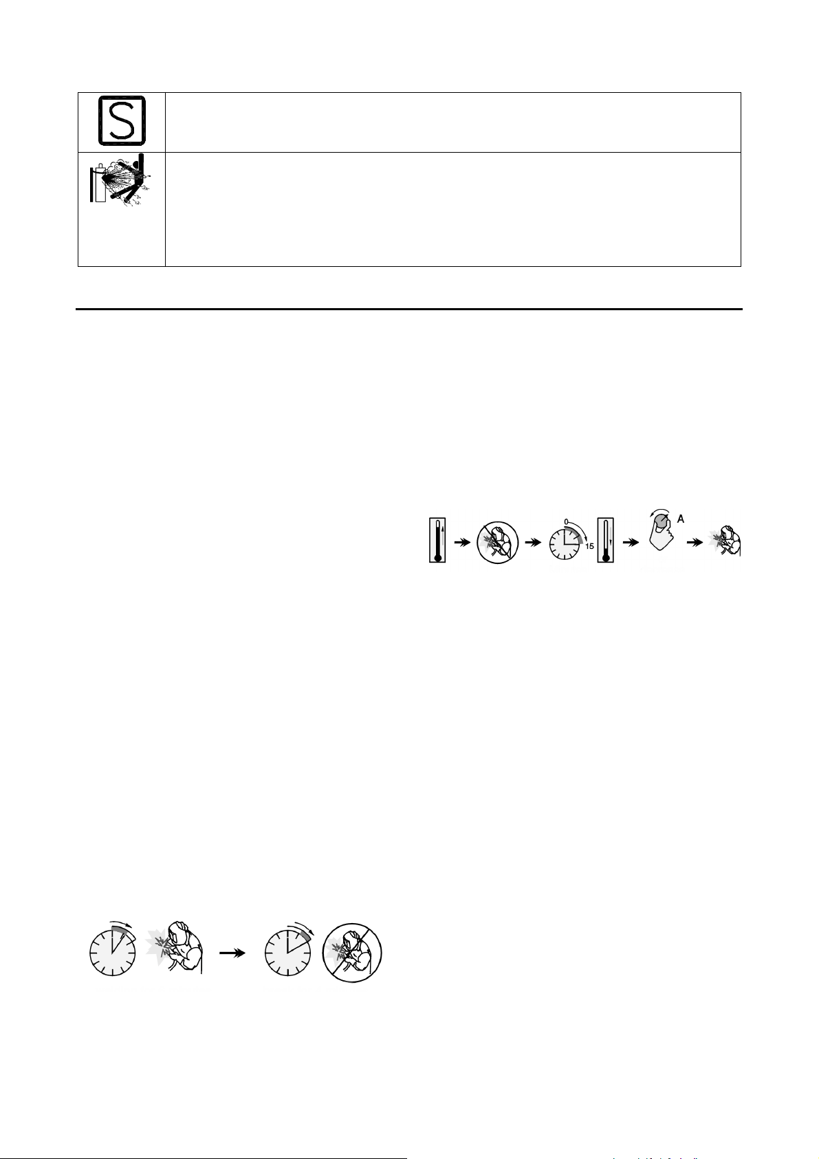
Duty cycle and Overheating
The duty cycle of a welding machine is the percentage of
time in a 10 minute cycle at which the welder can
operate the machine at rated welding current.
20% duty cycle:
Welding for 2 minutes. Break for 8 minutes.
Excessive extension of the duty cycle will cause the
thermal protection circuit to activate.
The welding transformer in the machine is protected
from overheating by a thermostat. When the machine is
overheated the output of the machine will turn “OFF“,
and the Thermal Indicator Light will turn “ON“. When the
machine has cooled to a safe temperature the Thermal
Indicator Light will go out and the machine may resume
normal operation. Note: For safety reasons the machine
will not come out of thermal shutdown if the trigger on
the welding gun has not been released.
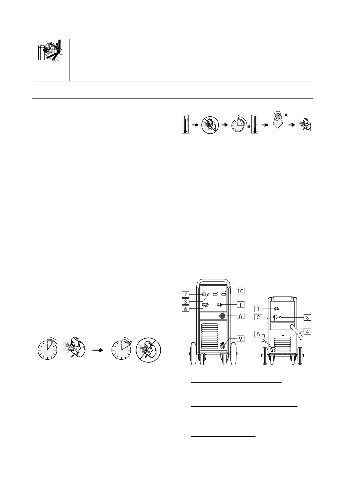
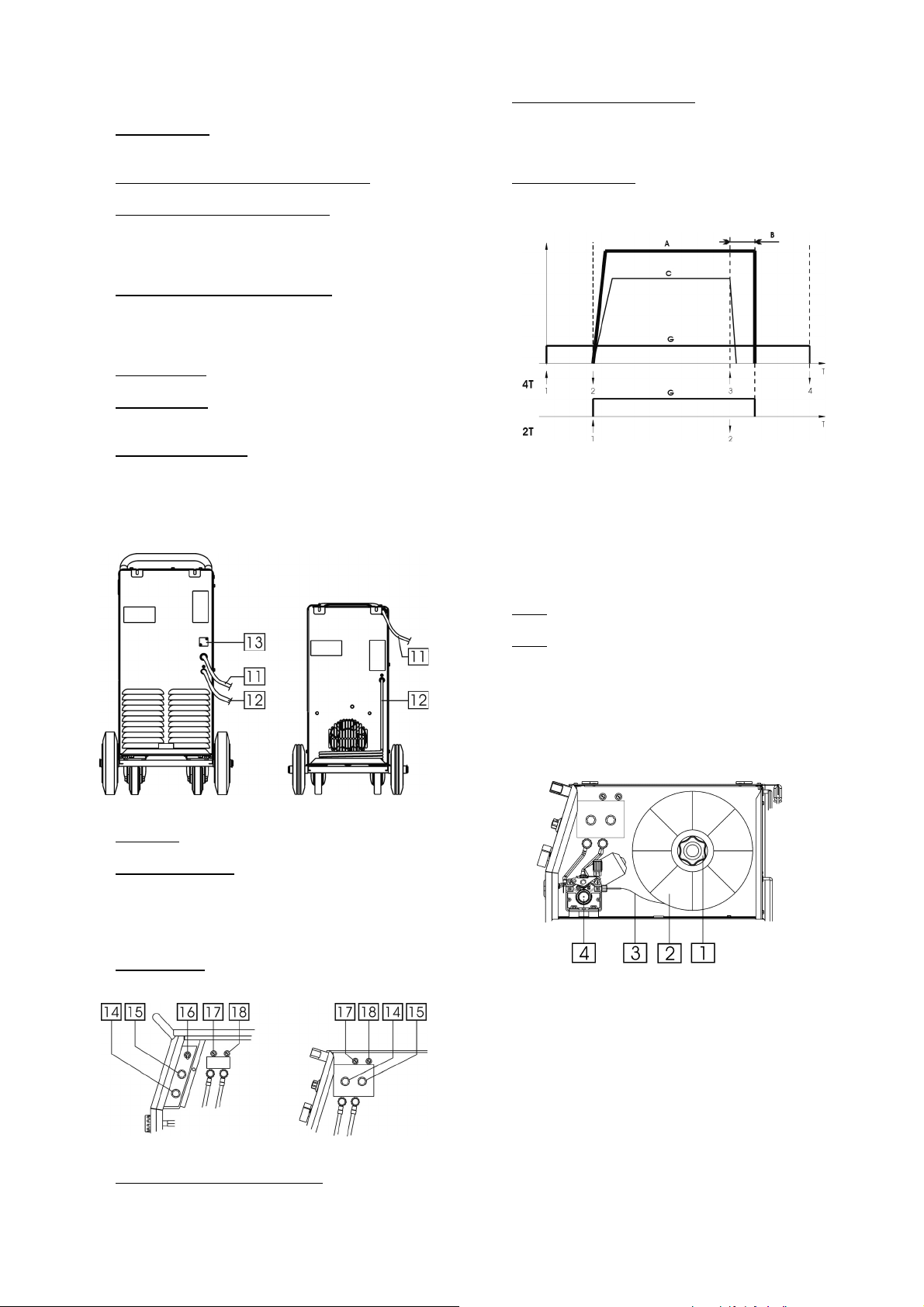
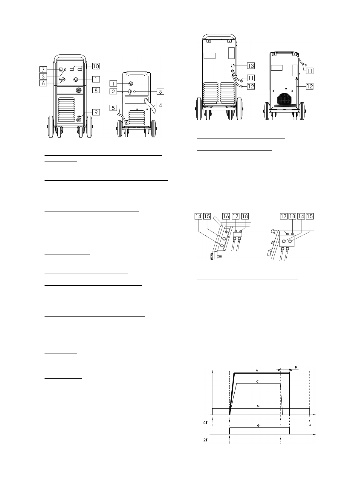
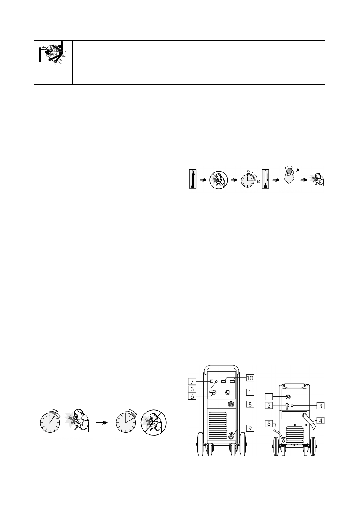
POWERTEC 191C/231C/271C POWERTEC 161C
1. WFS (Wire Feed Speed) Control Knob: It enables
continuous control of wire feeding speed in the
range from 1.0 to 20m/min
2. Power and Welding Voltage Changing Switch: It
enables to turn the machine ON and switching the
voltage. The POWERTEC 161C has a 7-steps
switch.
3. Thermal Overload Indicator: This lamp will light up
when the machine is overheated and the output has
been turned off. Leave the machine on to allow the
internal components to cool, when the lamp turns off
-2
A
normal operation is possible.
4. Welding Torch: Carry welding voltage, shield gas
and electrode wire.
15. Burnback Time Control Knob: It enables to obtain
the desired length of electrode wire, which protrudes
from the tip of the torch after ending welding;
adjusting range from 20 to 250ms.
5. Return Welding Cable Fixed With Clamp.
6. Welding Voltage Changing Switch: The
POWERTEC 191C has a 8-steps switch. The
POWERTEC 231C and 271C have a 12-steps
switch.
7. Power Switch and Power Indicator: After input
power is connected and the power switch is turned
on, the indicator will light up to indicate the machine
is ready to weld.
8. EURO Socket: For connecting welding torch.
9. Output Socket: For connecting the return welding
cable.
10. Digital Display Panel: Available as the option
K14044-1 (see chapter “Accessories”). It displays
welding parameters - welding voltage in [V] and
welding current in [A]. After finishing welding
process, it shows the average value of welding
parameters.
16. Torch Mode Switch: It enables selection of 2-step
or 4-step torch mode. The functionality of 2T/4T
mode is shown in the picture below:
Trigger pressed
↑
Trigger released
↓
A. Welding Current.
B. Burnback time.
C. WFS.
G. Gas.
17. Fuse: This fuse (1A) protects the PC Board.
POWERTEC 191C/231C/271C POWERTEC 161C
11. Gas hose.
12. Power Input Cable: Connect the proper plug to the
input cable to the rated output, in accord to
appropriate rules (for POWERTEC 191C, 231C and
271C only). Only qualified personnel shall connect
this plug.
13. Hole Covered: For CO
(see chapter “Accessories”).
gas heater kit K14048-1
2
18. Fuse: This fuse (4A) protects the wire feeder motor.
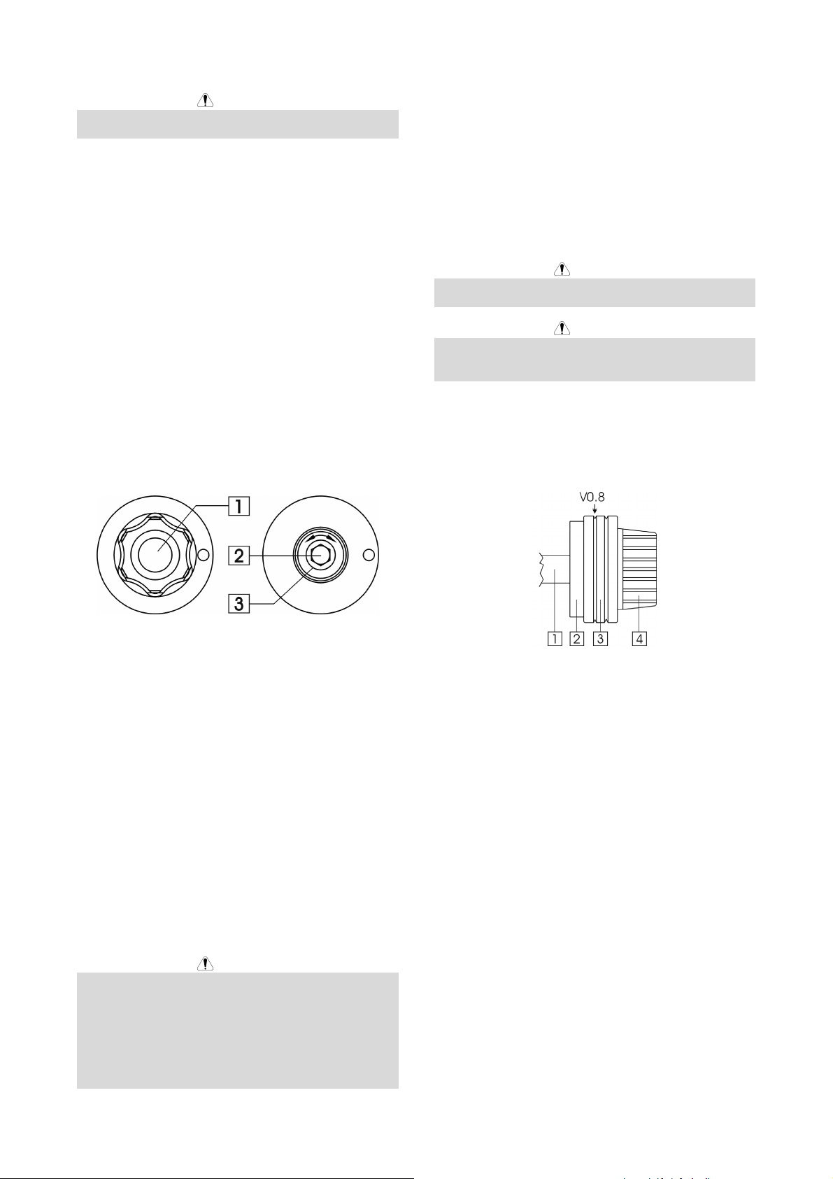
Loading the Wire Spool
Load the wire spool on the sleeve such that the spool
turns clockwise when the wire is fed into the wire feeder.
Machine is designed to use 15kg (300mm) wire spool.
For 5kg (200mm) wire spool use enclosed adaptor.
1. Sleeve
2. Wire spool
3. Electrode wire
4. Feeding unit
Make sure that the spool locating pin on sleeve goes into
the fitting hole on the spool.
Free the end of the wire and cut off the bent end making
POWERTEC 191C/231C/271C POWERTEC 161C
14. Spot Welding Time Control Knob: It enables time
control in the range from 0.2 to 8 s.
sure it has no burr.
Rotate the wire spool clockwise and thread the end of
the wire into the entrance guide tube pushing it into the
wire guide of the welding torch.
-3
A
WARNING
Clean the wire liner with compressed air when replacing
the wire spool, especially if you use FCAW 1,1mm wire.
Feeding the Electrode Wire
Rise side cover of the machine.
Inserting Electrode Wire into Welding
Torch
Remove the gas diffuser and contact tip from the
welding gun.
Set wire feeding speed knob in its central position.
Put on the drive roll using the correct groove
corresponding to the wire diameter.
Load the spool of wire onto the sleeve of the machine.
Free the end of the wire and cut off the bent end making
sure it has no burr.
Insert the electrode wire into to the wire feeder.
Properly adjust the wire tension arm of the feeder.
Adjustments of Brake Torque of Sleeve
To avoid spontaneous unrolling of the welding wire the
sleeve is fitted with a brake.
Adjustment is carried by rotation of its screw M10, which
is placed inside of the sleeve frame after unscrewing the
fastening cap of the sleeve.
After switching the machine “ON” press the torch button
until the electrode wire leaves the contact tip of the
welding torch.
WARNING
Take precaution to keep eyes and hands away from the
end of the torch while feeding wire.
WARNING
Once the wire has finished feeding through the welding
gun turn the machine “OFF“ before replacing to contact
tip and gas diffuser.
Assembling of the Drive Roll of the
Wire Feeder
The machine has V0.8/V1.0 drive roll in standard. The
picture below shown the assembly of drive roll for 0.8
solid wire.
1. Fastening cap.
2. Adjusting screw M10.
3. Pressing spring.
Turning the screw M10 clockwise increases the spring
tension and you can increase the brake torque.
Turning the screw M10 counterclockwise decreases the
spring tension and you can decrease the brake torque.
After finishing of adjustment, you should screw in the
fastening cap again.
Adjusting of Force of Pressure Roll
Force
Before welding you should understand how to properly
set the wire tension.
Pressure force is adjusted by turning the adjustment nut
clockwise to increase force, counterclockwise to
decrease force.
WARNING
If the roll pressure is too low the roll will slide on the wire.
If the roll pressure is set too high the wire may be
deformed, which will cause feeding problems in the
welding gun. The pressure force should be set properly.
Decrease the pressure force slowly until the wire just
begins to slide on the drive roll and then increase the
force slightly by turning of the adjustment nut by one
turn.
1. Motor shaft.
2. Mount ring.
3. Drive roll.
4. Cap.
To disassemble the drive roll you should:
• Release the wire tension arm of the wire feeder.
• Unscrew the fastening cap.
• Take off the drive roll from the mount ring.
To assemble the drive roll you should:
• Put on the drive roll onto the mounting ring.
• Screw in the fastening cap onto the mount ring.
• Insert the electrode wire.
• Engage the wire tension arm of the feeder.
Gas Supplying
Put the gas cylinder on the machine shelf secure it with
the chain.
Take off the safety cap from the shielding gas cylinder
and install the flow regulator on it.
Connect the gas hose of the machine to the regulator
with the clamp band.
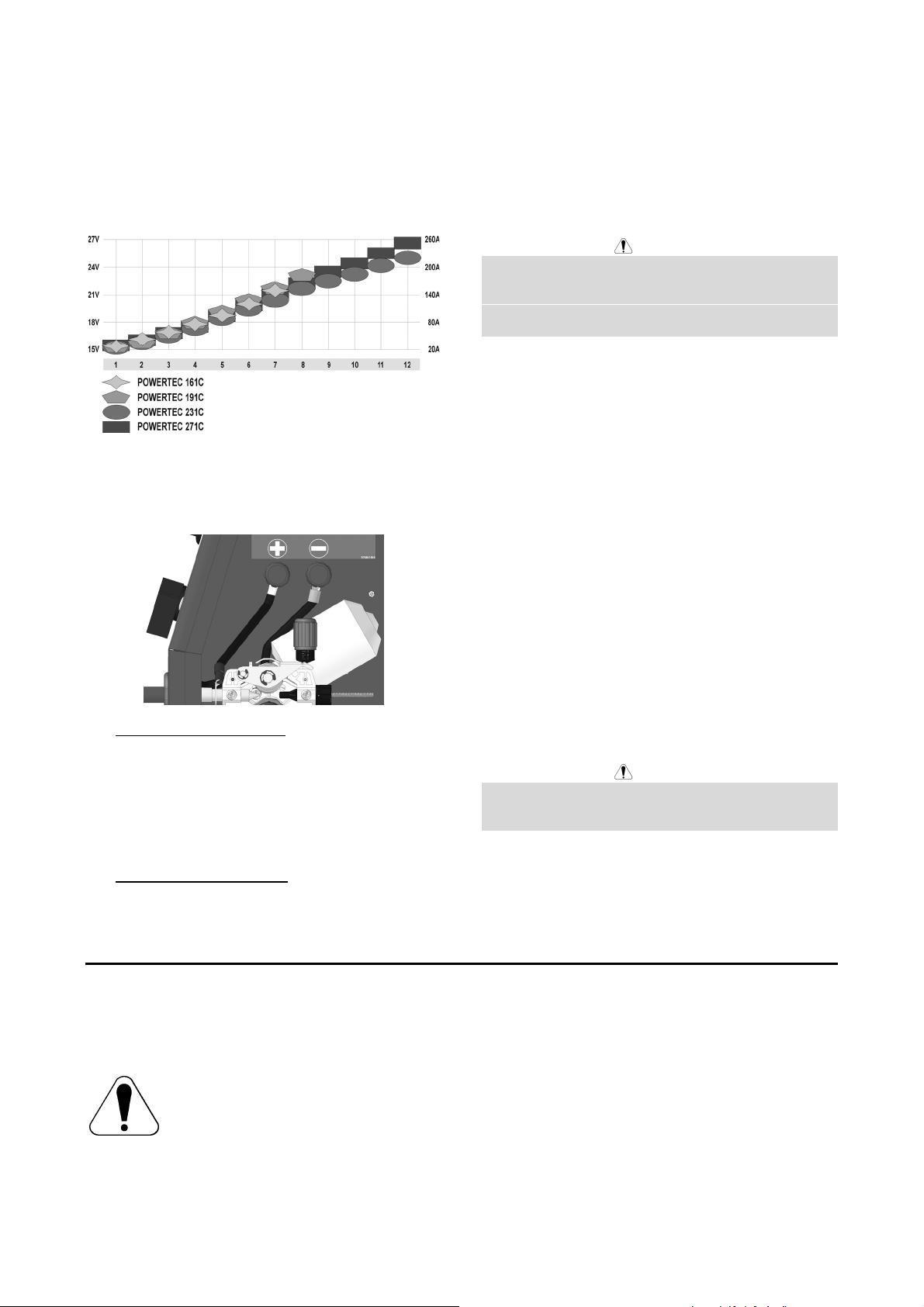
Welding with MIG / MAG method
To begin welding process with MIG/MAG method you
should:
-4
A
• Insert the plug of input supply cable into the main
socket.
• Switch ON the machine with the “Power Switch”.
• Insert the electrode wire into the torch.
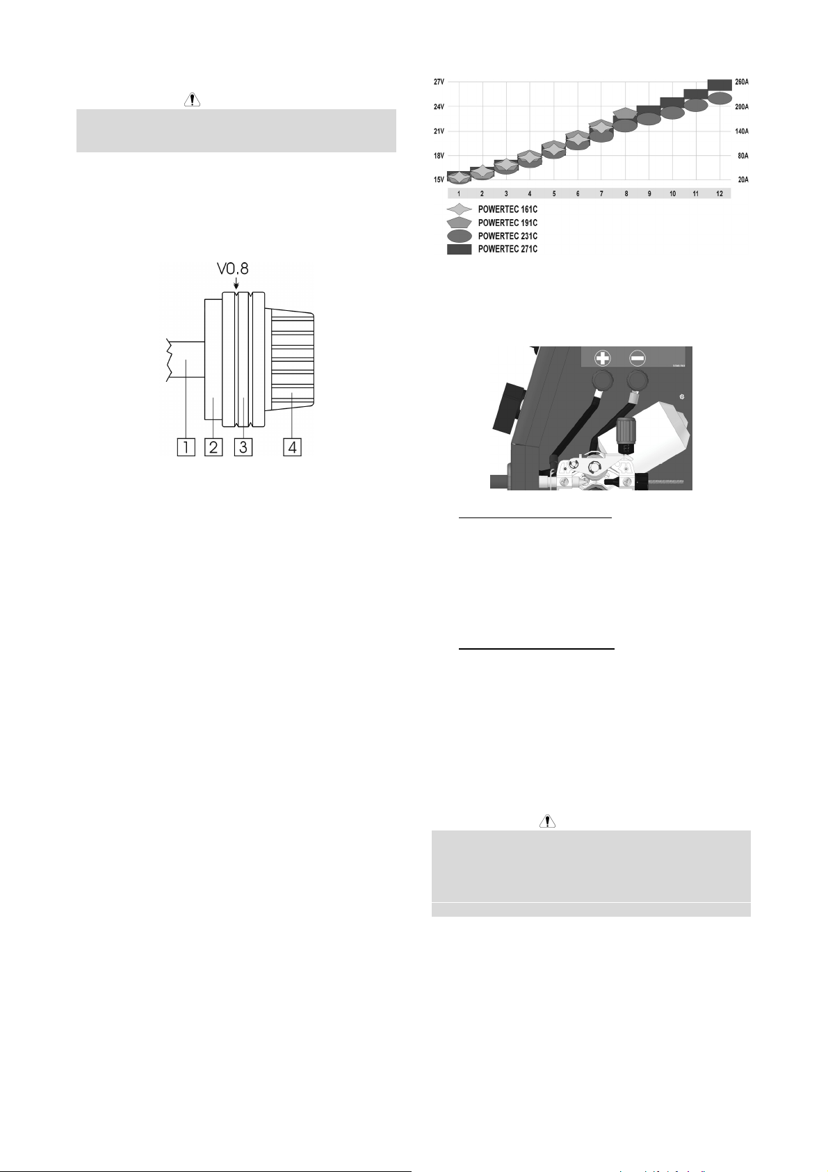
• According to selected welding mode and material
thickness set proper welding voltage and wire
feeding speed. The chart below can be useful for
welding setting selection:
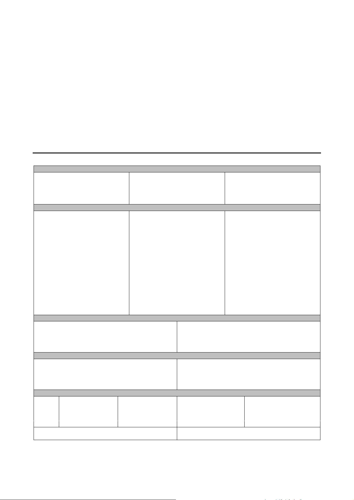
• connect Return Welding Cable to the Positive
(+) output terminal.
This is the typical configuration for most of the
Innershield wires (Flux Cored Arc Welding SelfShielded / FCAW-S).
Maintenance
WARNING
For any maintenance or repair operations it is
recommended to contact the nearest technical service
center or Lincoln Electric. Maintenance or repairs
performed by unauthorized service centers or personnel
will null and void the manufacturers warranty.
The frequency of the maintenance operations may vary
in accordance with the working environment where the
machine is placed.
Any noticeable damage should be reported immediately.
• Obeying the appropriate rules, you can begin to
weld.
Changing Polarity
1. For Positive Polarity (DC +):
• connect Welding Torch Cable to the Positive
(+) output terminal.
• connect Return Welding Cable to the Negative
(-) output terminal.
This is the typical configuration for the Metal Inert
Gas (MIG).
2. For Negative Polarity (DC -):
• connect Welding Torch Cable to the Negative
(-) output terminal.
Routine maintenance (everyday)
• Check cables and connections integrity. Replace, if
necessary.
• Remove the spatters from the welding gun nozzle.
Spatters could interfere with the shielding gas flow
to the arc.
• Check the welding gun condition: replace it, if
necessary.
• Check condition and operation of the cooling fan.
Keep clean its airflow slots.
Periodic maintenance (every 200 working hours
but not more rarely than once a year)
Perform the routine maintenance and, in addition:
• Keep clean the machine. Using a dry ( and low
pressure) airflow, remove the dust from the external
case and from inside of the cabinet.
• Check and tighten all screws.
WARNING
Mains supply network must be disconnected from the
machine before each maintenance and service. After
each repair, perform proper tests to ensure safety.
Electromagnetic Compatibility (EMC)
This machine has been designed in accordance with all relevant directives and standards. However, it may still generate
electromagnetic disturbances that can affect other systems like telecommunications (telephone, radio, and television) or
other safety systems. These disturbances can cause safety problems in the affected systems. Read and understand
this section to eliminate or reduce the amount of electromagnetic disturbance generated by this machine.
This machine has been designed to operate in an industrial area. To operate in a domestic area it is necessary to
observe particular precautions to eliminate possible electromagnetic disturbances. The operator must
install and operate this equipment as described in this manual. If any electromagnetic disturbances are
detected the operator must put in place corrective actions to eliminate these disturbances with, if
necessary, assistance from Lincoln Electric.
Before installing the machine, the operator must check the work area for any devices that may malfunction because of
electromagnetic disturbances. Consider the following.
• Input and output cables, control cables, and telephone cables that are in or adjacent to the work area and the
machine.
-5
11/04
A
• Radio and/or television transmitters and receivers. Computers or computer controlled equipment.
• Safety and control equipment for industrial processes. Equipment for calibration and measurement.
• Personal medical devices like pacemakers and hearing aids.
• Check the electromagnetic immunity for equipment operating in or near the work area. The operator must be sure
that all equipment in the area is compatible. This may require additional protection measures.
• The dimensions of the work area to consider will depend on the construction of the area and other activities that are
taking place.
Consider the following guidelines to reduce electromagnetic emissions from the machine.
• Connect the machine to the input supply according to this manual. If disturbances occur if may be necessary to take
additional precautions such as filtering the input supply.
• The output cables should be kept as short as possible and should be positioned together. If possible connect the
work piece to ground in order to reduce the electromagnetic emissions. The operator must check that connecting
the work piece to ground does not cause problems or unsafe operating conditions for personnel and equipment.
• Shielding of cables in the work area can reduce electromagnetic emissions. This may be necessary for special
applications.
Technical Specifications
POWERTEC 161C, 191C, 231C & 271C
INPUT
Input Power at Rated Output
Input Voltage
230 ± 10%
Single Phase
Duty Cycle
(Based on a 10 min. period)
161C:
161C:
191C:
231C:
271C:
20%
60%
100%
6.0 kVA @ 20% Duty Cycle
8.2 kVA @ 20% Duty Cycle
10.6 kVA @ 20% Duty Cycle
12.9 kVA @ 20% Duty Cycle
RATED OUTPUT AT 40°C
Output Current Output Voltage
150A
87A
70A
Frequency
50/60 Hz
21.5 Vdc
18.7 Vdc
17.5 Vdc
191C:
231C:
271C:
161C:
191C:
231C:
271C:
161C:
191C:
231C:
271C:
161C:
191C:
231C:
271C:
20%
60%
100%
20%
60%
100%
20%
60%
100%
180A
105A
80A
220A
130A
100A
255A
150A
120A
23.0 Vdc
19.3 Vdc
18.0 Vdc
25.0 Vdc
20.5 Vdc
19.0 Vdc
26.8 Vdc
21.5 Vdc
20.0 Vdc
OUTPUT RANGE
Welding Current Range Maximum Open Circuit Voltage
30A - 150A
30A - 180A
30A - 220A
30A - 255A
161C:
191C:
231C:
271C:
37 Vdc
42 Vdc
45 Vdc
47 Vdc
RECOMMENDED INPUT CABLE AND FUSE SIZES
Fuse or Circuit Breaker Size Input Power Cable
16A Superlag
20A Superlag
25A Superlag
32A Superlag
161C:
191C:
231C:
271C:
3 Conductor, 1.5mm
3 Conductor, 2.5mm
3 Conductor, 2.5mm
3 Conductor, 4.0mm
PHYSICAL DIMENSIONS
Height Width Length Weight
615 mm 390 mm 825 mm 53 kg
765 mm 427 mm 850 mm 70 kg
765 mm 427 mm 850 mm 80 kg
765 mm 427 mm 850 mm 83 kg
Operating Temperature
-10°C to +40°C
Storage Temperature
-25°C to +55°C
2
2
2
2
-6
Sicurezza
11/04
AVVERTENZA
Questa macchina deve essere impiegata solo da personale qualificato. Assicuratevi che tutte le procedure di
installazione, impiego, manutenzione e riparazione vengano eseguite solamente da persone qualificate. Leggere e
comprendere questo manuale prima di mettere in funzione la macchina. La mancata osservanza delle istruzioni di
questo manuale può provocare seri infortuni, anche mortali, alle persone, o danni alla macchina. Leggere e
comprendere le spiegazioni seguenti sui simboli di avvertenza. La Lincoln Electric non si assume alcuna responsabilità
per danni conseguenti a installazione non corretta, incuria o impiego in modo anormale.
AVVERTENZA: Questo simbolo indica che occorre seguire le istruzioni per evitare seri infortuni,
anche mortali, alle persone o danni a questa macchina. Proteggete voi stessi e gli altri dalla
possibilità di seri infortuni anche mortali.
LEGGERE E COMPRENDERE LE ISTRUZIONI: Leggere e comprendere questo manuale prima di
far funzionare la macchina. La saldatura ad arco può presentare dei rischi. La mancata osservanza
delle istruzioni di questo manuale può provocare seri infortuni, anche mortali, alle persone o danni alla
macchina.
LA FOLGORAZIONE ELETTRICA E’ MORTALE: Le macchine per saldatura generano tensioni
elevate. Non toccate l’elettrodo, il morsetto di massa o pezzi da saldare collegati alla macchina
quando la macchina è accesa. Mantenetevi isolati elettricamente da elettrodo, morsetto e pezzi
collegati a questo.
MACCHINA CON ALIMENTAZIONE ELETTRICA: Togliere l’alimentazione con l’interruttore ai fusibili
prima di svolgere operazioni su questa macchina. Mettere la macchina a terra secondo le normative
vigenti.
MACCHINA CON ALIMENTAZIONE ELETTRICA: Ispezionare periodicamente i cavi di
alimentazione, all’elettrodo e al pezzo. Se si riscontrano danni all’isolamento sostituire
immediatamente il cavo. Non posare la pinza portaelettrodo direttamente sul banco di saldatura o
qualsiasi altra superficie in contatto con il morsetto di massa per evitare un innesco involontario
dell’arco.
I CAMPI ELETTRICI E MAGNETICI POSSONO ESSERE PERICOLOSI: Il passaggio di corrente
elettrica in un conduttore produce campi elettromagnetici. Questi campi possono interferire con alcuni
cardiostimolatori (“pacemaker”) e i saldatori con un cardiostimolatore devono consultare il loro medico
su possibili rischi prima di impiegare questa macchina.
CONFORMITÀ CE: Questa macchina è conforme alle Direttive Europee.
FUMI E GAS POSSONO ESSERE PERICOLOSI: La saldatura può produrre fumi e gas dannosi alla
salute. Evitate di respirare questi fumi e gas. Per evitare il pericolo l’operatore deve disporre di una
ventilazione o di un'estrazione di fumi e gas che li allontanino dalla zona in cui respira.
I RAGGI EMESSI DALL’ARCO BRUCIANO: Usate una maschera con schermatura adatta a
proteggervi gli occhi da spruzzi e raggi emessi dall’arco mentre saldate o osservate la saldatura.
Indossare indumenti adatti in materiale resistente alla fiamma per proteggere il corpo, sia vostro che
dei vostri aiutanti. Le persone che si trovano nelle vicinanze devono essere protette da schermature
adatte, non infiammabili, e devono essere avvertite di non guardare l’arco e di non esporvisi.
GLI SPRUZZI DI SALDATURA POSSONO PROVOCARE INCENDI O ESPLOSIONI: Allontanare
dall'area di saldatura quanto può prendere fuoco e tenere a portata di mano un estintore. Gli spruzzi
o altri materiali ad alta temperatura prodotti dalla saldatura attraversano con facilità eventuali piccole
aperture raggiungendo le zone vicine. Non saldare su serbatoi, bidoni, contenitori o altri materiali fino
a che non si sia fatto tutto il necessario per assicurarsi dell'assenza di vapori infiammabili o nocivi.
Non impiegare mai questa macchina se vi è presenza di gas e/o vapori infiammabili o combustibili
liquidi.
I MATERIALI SALDATI BRUCIANO: Il processo di saldatura produce moltissimo calore. Ci si può
bruciare in modo grave con le superfici e materiali caldi della zona di saldatura. Impiegare guanti e
pinze per toccare o muovere materiali nella zona di saldatura.
B-1
MARCHIO DI SICUREZZA: Questa macchina è adatta a fornire energia per operazioni di saldatura
svolte in ambienti con alto rischio di folgorazione elettrica.
LE BOMBOLE POSSONO ESPLODERE SE SONO DANNEGGIATE: Impiegate solo bombole
contenenti il gas compresso adatto al processo di saldatura utilizzato e regolatori di flusso, funzionanti
regolarmente, progettati per il tipo di gas e la pressione in uso. Le bombole vanno tenute sempre in
posizione verticale e assicurate con catena ad un sostegno fisso. Non spostate le bombole senza il
loro cappello di protezione. Evitate qualsiasi contatto dell’elettrodo, della sua pinza, del morsetto di
massa o di ogni altra parte in tensione con la bombola del gas. Le bombole gas vanno collocate
lontane dalle zone dove possano restare danneggiate dal processo di saldatura con relativi spruzzi e
da fonti di calore.
Installazione e Istruzioni Operative
Leggere tutta questa sezione prima di installare e
impiegare la macchina.
Collocazione e ambiente
Questa macchina è in grado di funzionare in ambienti
difficili. E’ comunque importante seguire delle semplici
misure di prevenzione per garantirne una lunga durata e
un funzionamento affidabile.
• Non collocare o impiegare la macchina su superfici
inclinate più di 15° rispetto all’orizzontale.
• Non usare questa macchina per sgelare tubi.
• La macchina va collocata ove vi sia una circolazione
di aria pulita senza impedimenti al suo movimento in
entrata e uscita dalle feritoie. Non coprire la
macchina con fogli di carta, panni o stracci quando
è accesa.
• Tenere al minimo polvere e sporco che possano
entrare nella macchina.
• Questa macchina ha una protezione di grado IP23.
Tenetela più asciutta possibile e non posatela su
suolo bagnato o dentro pozzanghere.
• Disponete la macchina lontana da macchinari
controllati via radio. Il suo funzionamento normale
può interferire negativamente sul funzionamento di
macchine controllate via radio poste nelle vicinanze,
con conseguenze di infortuni o danni materiali.
Leggete la sezione sulla compatibilità
elettromagnetica di questo manuale.
• Non impiegate la macchina in zone ove la
temperatura ambiente supera i 40°C.
Fattore di Intermittenza e
Surriscaldamento
Il fattore di intermittenza di una saldatrice è la
percentuale di tempo su un periodo di 10 minuti durante
la quale si può far funzionare la macchina alla corrente
nominale corrispondente.
Fattore di intermittenza 20%:
Il superamento del fattore di intermittenza provoca
l’attivazione del circuito di protezione termica.
Un termostato protegge dal surriscaldamento il
trasformatore di saldatura. Se la macchina si
surriscalda, l’uscita viene interrotta e si accende la spia
dell’indicatore termico. Una volta raffreddata la
macchina a temperatura di sicurezza, la spia indicatore
termico si spegne e la macchina può riprendere il
funzionamento normale. Nota: Per motivi di sicurezza la
macchina non esce dall’arresto “termico” se non si è
rilasciato il pulsante torcia.
Minuti o ridurre il
fattore di
intermittenza
Collegamento all’alimentazione
L’installazione e la presa dalla rete di alimentazione
devono essere realizzate e protette secondo la
normativa vigente.
Prima di accendere la macchina verificare tensione, fasi
e frequenza dell’alimentazione. Controllare il
collegamento dei cavi di messa a terra fra la macchina e
la sua alimentazione. Tensioni di alimentazione
ammissibili: 1x230V 50Hz/60Hz. Per ulteriori
informazioni sull’alimentazione fare riferimento alla
Sezione Specifiche tecniche del manuale e alla targhetta
dati della macchina.
Assicuratevi che l’alimentazione fornisca una potenza
sufficiente per il funzionamento normale della macchina.
Nella sezione “Specifiche tecniche” di questo manuale
sono indicate le dimensioni necessarie per i fusibili
ritardati (o interruttori automatici con caratteristica tipo
"D") e cavi.
saldatura per 2 minuti interruzione per 8 minuti
B-2
Comandi e possibilità operative
POWERTEC 191C/231C/271C POWERTEC 161C
POWERTEC 191C/231C/271C POWERTEC 161C
1. Manopola di regolazione velocità filo (WFS - Wire
Feed Speed): Permette la regolazione continua
della velocità filo nella gamma fra 1.0 e 20m/min.
2. Interruttore generale e cambio tensione di saldatura:
Serve per accendere il generatore e cambiare il
valore di tensione di saldatura. Il POWERTEC
161C ha un selettore a 7 posizioni.
3. Spia indicatrice di sovraccarico termico: Questa
luce si accende quando la macchina si surriscalda e
l’uscita viene interrotta. Lasciare accesa la
macchina per permettere il raffreddamento dei
componenti interni; quando la spia si spegne è
possibile riprendere il funzionamento normale.
4. Torcia di saldatura: Include cavo di corrente e tubo
gas.
5. Cavo massa fissato con serracavo.
6. Interruttore cambio tensione di saldatura: La
POWERTEC 191C ha un selettore a 8 posizioni. La
POWERTEC 231C e 271C hanno un selettore a 12
posizioni.
7. Interruttore generale e spia di accensione: Dopo
che il cavo di alimentazione è stato collegato alla
rete elettrica e si è posizionato su ON l’interruttore
generale, la spia di accensione si accenderà
indicando che la macchina è pronta per saldare.
8. Presa EURO: Per collegare la torcia.
9. Presa “ – “: Per collegare il cavo massa.
11. Tubo gas da collegarsi alla bombola.
12. Cavo di alimentazione elettrica: Collegare al cavo
di alimentazione una spina adeguata alle
caratteristiche previste seguendo le prescrizioni
della normativa (sole per POWERTEC 191C, 231C
e 271C). Soltanto personale qualificato può
eseguire il collegamento.
13. Foro con coperchio: Per eventuale presa optional
per il preriscaldamento del gas CO2 (vedi sezione
“accessori”).
POWERTEC 191C/231C/271C POWERTEC 161C
14. Manopola regolazione tempo di puntatura:
Permette di regolare il tempo di puntatura da 0.2 a 8
secondi.
15. Manopola di regolazione del tempo di bruciatura filo:
Permette di ottenere la lunghezza desiderata di filo
elettrodo che resta sporgente dalla punta della
torcia a fine saldatura; gamma di regolazione da 20
a 250ms.
16. Commutatore modo Pulsante Torcia: Permette di
selezionare la modalità 2 Tempi o 4 Tempi per il
pulsante torcia. La funzione 2 o 4 tempi è descritta
nei disegni seguenti:
10. Display digitale: Disponibile come optional, codice
ordinazione K14044-1 (vedi sezione “accessori”).
Visualizza i parametri di saldatura – Tensione di
saldatura in [ V ] e corrente di saldatura in [A].
Dopo ogni saldatura visualizza i valori medi dei
parametri utilizzati.
B-3
Pulsante premuto
↑
Pulsante rilasciato
↓

A. Corrente di saldatura.
B. Bruciatura filo (Burn-Back).
C. Velocità filo (WFS).
G. Gas.
17. Fusibile: Questo fusibile da 1A protegge la scheda
di controllo.
18. Fusibile: Questo fusibile da 4A protegge il motore
trainafilo.
Caricamento della bobina filo
Caricare la bobina sull’adattatore in modo che la bobina
giri in senso orario quando il filo avanza nel trainafilo.
La macchina è progettata per l’impiego di bobine da 15
kg (300 mm). Per uso con bobine da 5kg (200mm)
usare l’adattatore incluso.
Regolazione della coppia frenante
dell’adattatore.
L’adattatore è munito di un freno che evita lo
srotolamento spontaneo del filo.
La regolazione si effettua ruotando la vite M10, collocata
dentro il telaio dell’adattatore (dopo aver svitato il
coperchietto di fissaggio dell’adattatore).
1. Coperchietto di fissaggio.
2. Vite M10 di regolazione.
3. Molla di compressione.
Ruotando la vite M10 in senso orario si comprime di più
la molla e si aumenta la coppia frenante.
Ruotando la vite M10 in senso antiorario si scarica la
molla e si diminuisce la coppia frenante.
1. Adattatore.
2. Bobina filo.
3. Filo elettrodo.
4. Gruppo trainafilo.
Verificate che il perno di posizionamento bobina
sull’adattatore si impegni nel foro apposito sulla bobina.
Liberate l’estremità del filo e tagliatene via la parte piegata
accertando che non restino sfrangiature.
Ruotate la bobina in senso orario e infilate l’estremità del
filo nel guidafilo di ingresso spingendolo fino al guidafilo
della torcia.
AVVERTENZA
Pulire la guaina della torcia con aria compressa quando
si sostituisce la bobina del filo, specialmente se si è
utilizzato filo animato.
Inserimento del filo elettrodo
Sollevate il coperchio laterale della macchina.
Applicate il rullo motore dotato della scanalatura
corrispondente al diametro filo.
Caricate la bobina filo sull’adattatore.
Liberate l’estremità del filo e tagliatene via la parte piegata
accertando che non siano rimaste sfrangiature.
Completata la regolazione ricordarsi di riavvitare il
coperchietto di fissaggio.
Regolazione della pressione del rullo
folle
Prima di cominciare a saldare è necessario capire bene
il modo di regolare con precisione la tensione meccanica
nel filo mediante il braccio di messa in tensione.
La pressione sul filo si regola ruotando il dado di
regolazione, in senso orario per aumentarla, antiorario
per diminuirla.
AVVERTENZA
Se la pressione del rullo è troppo bassa, il rullo slitterà
su filo. Se la pressione è eccessiva il filo può deformarsi
provocando problemi di avanzamento nella torcia.
Regolate la pressione con precisione. Diminuitela
lentamente fino a che il filo comincia appena a scivolare
sul rullo motore, e poi riaumentatela un po’ dando un
solo giro in più al dado.
Inserimento del filo elettrodo nella
torcia di saldatura
Rimuovere dalla torcia il diffusore gas e la punta di
contatto.
Portare la manopola della velocità avanzamento filo in
posizione centrale sulla sua scala.
Dopo aver acceso la macchina, premere il pulsante della
torcia sino a che il filo non fuoriesce dalla punta di
contatto.
Inserite il filo elettrodo nel gruppo trainafilo.
Regolate esattamente il braccio di messa in tensione del
trainafilo.
AVVERTENZA
Mentre il filo avanza fare attenzione a tenere mani ed
occhi lontani dalla punta della torcia.
B-4
AVVERTENZA
Completato il passaggio del filo attraverso la torcia
spegnere la macchina prima di rimettere sulla torcia la
punta di contatto e il diffusore gas.
Assiemaggio del rullo motore sul
gruppo trainafilo
La configurazione standard della macchina prevede un
rullo motore V0.8/V1.0. Il disegno mostra l’assiemaggio
di un rullo da filo pieno 0.8 mm.
1. Asse motore.
2. Anello di montaggio.
3. Rullo motore.
4. Coperchietto.
Per smontare il rullo motore occorre:
• Allentare il braccio di messa in tensione del filo sul
trainafilo.
• Svitare il coperchietto di fissaggio.
• Sfilare il rullo dall’anello di montaggio.
• Si può iniziare a saldare nel rispetto delle normative
e prescrizioni.
Cambio polarità
1. Per Polarità Positiva (DC +):
• Collegare il cavo della torcia sul terminale di
usciata positivo (+).
• Collegare il cavo di massa al terminale di
usciata negativo (-).
Questa è la tipica configurazione per la saldatura
(MIG).
Per montare il rullo motore occorre:
• Applicare il rullo sull’anello di montaggio.
• Avvitare sull’anello il coperchietto di montaggio.
• Far passare il filo elettrodo.
• Mettere in forza il braccio di messa in tensione.
Alimentazione del gas
Porre la bombola gas sulla piattaforma di cui è munita la
macchina e assicurarla con la catena.
Togliere il coperchio di sicurezza della bombola e
installare su questa il regolatore di flusso.
Collegare al regolatore il tubo gas in arrivo alla
macchina, bloccandolo con la fascetta.
Saldatura con metodo MIG / MAG
Per iniziare a saldare in MIG/MAG occorre:
• Inserire la spina del cavo di alimentazione nella
presa di rete.
• Accendere la macchina con l’interruttore generale.
• Inserire nella torcia il filo elettrodo.
• Fissare tensione di saldatura e velocità filo in
funzione del modo si saldatura e dello spessore del
materiale. La tabella seguente può essere di aiuto
per la selezione dei corretti parametri di saldatura:
2. Per Polarità Negativa (DC -):
• Collegare il cavo della torcia al terminale di
uscita negativo (-).
• Collegare il cavo massa al terminale di uscita
positivo (+).
Questa è la tipica configurazione per la maggior
parte dei procedimenti con filo Innershield ( FCAW-
S).
Manutenzione
AVVERTENZA
Per ogni operazione di manutenzione o riparazione si
raccomanda di rivolgersi al più vicino centro di
assistenza tecnica della Lincoln Electric. Manutenzioni o
riparazioni effettuate da personale o centri di servizio
non autorizzati fanno decadere la garanzia del
fabbricante.
La frequenza delle operazioni di manutenzione può
essere variata in funzione dell’ambiente in cui la
macchina si trova a lavorare.
Qualsiasi danno venga notato va immediatamente
riferito a chi di dovere.
B-5
Manutenzione corrente (quotidiana)
• Controllare che cavi e collegamenti siano integri.
Sostituirli, se necessario.
• Rimuovere gli spruzzi dal cono della torcia. Gli
spruzzi possono interferire con il flusso del gas di
protezione verso l’arco.
• Controllare lo stato della torcia: sostituirla, se
necessario.
• Controllare stato e funzionamento del ventilatore di
raffreddamento. Mantenerne pulite le feritoie.
Manutenzione periodica (ogni 200 ore di lavoro,
ma non meno di una volta all’anno)
Eseguire la manutenzione corrente e, in aggiunta:
• Pulire la macchina. Usare un getto d’aria asciutto e
a bassa pressione per rimuovere la polvere
dall’involucro esterno e dall’interno.
• Controllare e ristringere tutte le viti.
AVVERTENZA
Prima di svolgere qualsiasi operazione di manutenzione
e servizio staccare la macchina dalla rete di
alimentazione. Dopo ogni riparazione, eseguire le prove
necessarie ad assicurare la sicurezza.
Compatibilità Elettromagnetica (EMC)
Questa macchina è stata progettata nel rispetto di tutte le direttive e normative in materia. Tuttavia può generare dei
disturbi elettromagnetici che possono interferire con altri sistemi come le telecomunicazioni (telefono, radio o televisione)
o altri sistemi di sicurezza. I disturbi possono provocare problemi nella sicurezza dei sistemi interessati. Leggete e
comprendete questa sezione per eliminare o ridurre il livello dei disturbi elettromagnetici generati da questa macchina.
11/04
La macchina è stata progettata per funzionare in ambienti di tipo industriale. Il suo impiego in ambienti
domestici richiede particolari precauzioni per l’eliminazione dei possibili disturbi elettromagnetici.
L’operatore deve installare e impiegare la macchina come precisato in questo manuale. Se si riscontrano
disturbi elettromagnetici l’operatore deve porre in atto azioni correttive per eliminarli, avvalendosi, se
necessario, dell’assistenza della Lincoln Electric.
Prima di installare la macchina, controllate se nell’area di lavoro vi sono dispositivi il cui funzionamento potrebbe risultare
difettoso a causa di disturbi elettromagnetici. Prendete in considerazione i seguenti:
• Cavi di entrata o di uscita, cavi di controllo e cavi telefonici collocati nell’area di lavoro, presso la macchina o nelle
adiacenze di questa.
• Trasmettitori e/o ricevitori radio o televisivi. Computers o attrezzature controllate da computer.
• Impianti di sicurezza e controllo per processi industriali. Attrezzature di taratura e misurazione.
• Dispositivi medici individuali come cardiostimolatori (pacemakers) o apparecchi acustici.
• Verificare che macchine e attrezzature funzionanti nell’area di lavoro o nelle vicinanze siano immuni da possibili
disturbi elettromagnetici. L’operatore deve accertare che tutte le attrezzature e dispositivi nell’area siano compatibili.
A questo scopo può essere necessario disporre misure di protezione aggiuntive.
• L’ampiezza dell’area di lavoro da prendere in considerazione dipende dalla struttura dell’area e dalle altre attività
che vi si svolgono.
Per ridurre le emissioni elettromagnetiche della macchina tenete presenti le seguenti linee guida.
• Collegare la macchina alla fonte di alimentazione come indicato da questo manuale. Se vi sono disturbi, può essere
necessario prendere altre precauzioni, come un filtro sull’alimentazione.
• I cavi in uscita vanno tenuti più corti possibile e l’uno accanto all’altro. Se possibile mettere a terra il pezzo per
ridurre le emissioni elettromagnetiche. L’operatore deve controllare che questa messa a terra non provochi
problemi o pericoli alla sicurezza del personale e della macchina e attrezzature.
• Si possono ridurre le emissioni elettromagnetiche schermando i cavi nell’area di lavoro. Per impieghi particolari
questo può diventare necessario.
B-6
Specifiche Tecniche
POWERTEC 161C, 191C, 231C & 271C
Tensione di alimentazione
230 ± 10%
Monofase
Fattore di intermittenza
(su periodo di 10 minuti)
161C:
20%
60%
100%
161C:
191C:
231C:
271C:
ALIMENTAZIONE
Potenza assorbita per uscita nominale
6.0 kVA @ 20% Fattore di intermittenza
8.2 kVA @ 20% Fattore di intermittenza
10.6 kVA @ 20% Fattore di intermittenza
12.9 kVA @ 20% Fattore di intermittenza
USCITA NOMINALE a 40°C
Corrente in uscita Tensione nominale in uscita
150A
87A
70A
Frequenza
50/60 Hz
21.5 Vdc
18.7 Vdc
17.5 Vdc
191C:
231C:
271C:
161C:
191C:
231C:
271C:
161C:
191C:
231C:
271C:
161C:
191C:
231C:
271C:
20%
60%
100%
20%
60%
100%
20%
60%
100%
180A
105A
80A
220A
130A
100A
255A
150A
120A
23.0 Vdc
19.3 Vdc
18.0 Vdc
25.0 Vdc
20.5 Vdc
19.0 Vdc
26.8 Vdc
21.5 Vdc
20.0 Vdc
USCITA
Gamma corrente di saldatura Massima tensione a vuoto
30A - 150A
30A - 180A
30A - 220A
30A - 255A
161C:
191C:
231C:
271C:
37 Vdc
42 Vdc
45 Vdc
47 Vdc
DIMENSIONI RACCOMANDATE PER CAVI E FUSIBILI
Taglia Fusibile o Interruttore Automatico Cavo di alimentazione
16A Ritardato
20A Ritardato
25A Ritardato
32A Ritardato
161C:
191C:
231C:
271C:
3 conduttori da 1.5mm
3 conduttori da 2.5mm
3 conduttori da 2.5mm
3 conduttori da 4.0mm
DATI FISICI – DIMENSIONI
Altezza Larghezza Lunghezza Peso
615 mm 390 mm 825 mm 53 kg
765 mm 427 mm 850 mm 70 kg
765 mm 427 mm 850 mm 80 kg
765 mm 427 mm 850 mm 83 kg
Temperatura di impiego
–10°C a +40°C
Temperatura di immagazzinamento
-25°C a +55°C
2
2
2
2
B-7
Sicherheitsmaßnahmen / Unfallschutz
02/05
ACHTUNG
Diese Anlage darf nur von ausgebildetem Fachpersonal genutzt, gewartet und repariert werden. Schließen Sie dieses
Gerät nicht an, arbeiten Sie nicht damit oder reparieren Sie es nicht, bevor Sie diese Betriebsanleitung gelesen und
verstanden haben. Bei Nichtbeachtung der Hinweise kann es zu gefährlichen Verletzungen bis hin zum Tod oder zu
Beschädigungen am Gerät kommen. Beachten Sie auch die folgenden Beschreibungen der Warnhinweise. Lincoln
Electric ist nicht verantwortlich für Fehler, die durch inkorrekte Installation, mangelnde Sorgfalt oder Fehlbenutzung des
Gerätes entstehen.
ACHTUNG: Dieses Symbol gibt an, dass die folgenden Hinweise beachtet werden müssen, um
gefährliche Verletzungen bis hin zum Tode oder Beschädigungen am Gerät zu verhindern. Schützen
Sie sich und andere vor gefährlichen Verletzungen oder dem Tode.
BEACHTEN SIE DIE ANLEITUNG: Lesen Sie diese Anleitung sorgfältig, bevor Sie das Gerät in
Betrieb nehmen. Bei Nichtbeachtung der Hinweise kann es zu gefährlichen Verletzungen bis hin zum
Tod oder zu Beschädigungen am Gerät kommen.
STROMSCHLÄGE KÖNNEN TÖDLICH SEIN: Schweißgeräte erzeugen hohe Stromstärken.
Berühren Sie keine stromführenden Teile oder die Elektrode mit der Haut oder nasser Kleidung.
Schützen Sie beim Schweißen Ihren Körper durch geeignete isolierende Kleidung und Handschuhe.
ELEKTRISCHE GERÄTE: Schalten Sie die Netzspannung am Sicherungskasten aus oder ziehen Sie
den Netzstecker, bevor Arbeiten an der Maschine ausgeführt werden. Erden Sie die Maschine
gemäß den geltenden elektrischen Bestimmungen.
ELEKTRISCHE GERÄTE: Achten Sie regelmäßig darauf, dass Netz-, Werkstück- und
Elektrodenkabel in einwandfreiem Zustand sind und tauschen Sie diese bei Beschädigung aus.
Legen Sie den Elektrodenhalter niemals auf den Schweißarbeitsplatz, damit es zu keinem
ungewollten Lichtbogen kommt.
ELEKTRISCHE UND MAGNETISCHE FELDER BERGEN GEFAHREN: Elektrischer Strom, der
durch ein Kabel fließt, erzeugt ein elektrisches und magnetisches Feld (EMF). EMF Felder können
Herzschrittmacher beeinflussen. Bitte fragen Sie Ihren Arzt, wenn Sie einen Herzschrittmacher
haben, bevor Sie dieses Gerät benutzen.
CE Konformität: Dieses Gerät erfüllt die CE-Normen.
RAUCH UND GASE KÖNNEN GEFÄHRLICH SEIN: Schweißen erzeugt Rauch und Gase, die
gesundheitsschädlich sein können. Vermeiden Sie das Einatmen dieser Metalldämpfe. Benutzen Sie
eine Schweißrauchabsaugung, um die Dämpfe abzusaugen.
LICHTBÖGEN KÖNNEN VERBRENNUNGEN HERVORRUFEN: Tragen Sie geeignete
Schutzkleidung und Schutzmasken für Augen, Ohren und Körper, um sich vor Spritzern und
Strahlungen zu schützen. Warnen Sie auch in der Umgebung befindliche Personen vor den Gefahren
des Lichtbogens. Lassen Sie niemanden ungeschützt den Lichtbogen beobachten.
SCHWEISSPRITZER KÖNNEN FEUER ODER EXPLOSIONEN VERURSACHEN: Entfernen Sie
feuergefährliche Gegenstände vom Schweißplatz und halten Sie einen Feuerlöscher bereit.
Schweißen Sie keine Behälter, die brennbare oder giftige Stoffe enthalten, bis diese vollständig
geleert und gesäubert sind. Schweißen Sie niemals an Orten, an denen brennbare Gase, Stoffe oder
Flüssigkeiten vorhanden sind.
GESCHWEISSTE MATERIALIEN KÖNNEN VERBRENNUNGEN VERURSACHEN: Schweißen
verursacht hohe Temperaturen. Heiße Materialien können somit ernsthafte Verbrennungen
verursachen. Benutzen Sie Handschuhe und Zangen, wenn Sie geschweißte Materialien berühren
oder bewegen.
S-ZEICHEN: Dieses Gerät darf Schweißstrom in Umgebungen mit erhöhter elektrischer Gefährdung
liefern.
C-1
DEFEKTE GASFLASCHEN KÖNNEN EXPLODIEREN: Benutzen Sie nur Gasflaschen mit dem für
den Schweißprozess geeigneten Gas und ordnungsgemäßen Druckreglern, die für dieses Gas
ausgelegt sind. Lagern Sie Gasflaschen aufrecht und gegen Umfallen gesichert. Bewegen Sie keine
Gasflasche ohne Ihre Sicherheitskappe. Berühren Sie niemals eine Gasflasche mit der Elektrode,
Elektrodenhalter, Massekabel oder einem anderen stromführenden Teil. Gasflaschen dürfen nicht an
Plätzen aufgestellt werden, an denen sie beschädigt werden können, inklusive Schweißspritzern und
Wärmequellen.
Installation und Bedienungshinweise
Bitte diesen Abschnitt vor Montage und Inbetriebnahme
der Maschine vollständig durchlesen.
Aufstellungsort und -umgebung
Diese Maschine kann auch bei ungünstigen
Umgebungsbedingungen betrieben werden. Jedoch sind
dabei die folgenden Vorsichtsmaßnahmen zu beachten,
um einen sicheren Betrieb und eine lange Lebensdauer
der Maschine zu gewährleisten.
• Die Maschine darf nicht auf einer schrägen Fläche
aufgestellt oder betrieben werden, die eine Neigung
von mehr 15° aufweist.
• Die Maschine darf nicht zum Auftauen von Rohren
verwendet werden.
• Am Aufstellungsort der Maschine ist auf
ausreichende Frischluftzirkulation zu achten. Der
Luftstrom zu den Be- und Entlüftungsöffnungen darf
nicht behindert werden. Die Maschine bei Betrieb
nicht mit Papier, Stoff oder Putzlappen abdecken.
• Schmutz und Staub sind soweit wie möglich von der
Maschine fernzuhalten.
• Die Maschine verfügt über Schutzart IP23 und ist
daher so weit wie möglich trocken zu halten. Sie
darf nicht auf feuchtem oder nassem Untergrund
aufgestellt werden.
• Die Maschine nicht in der Nähe funk- oder
ferngesteuerter Geräte aufstellen. Der
Maschinenbetrieb könnte die Funktion von sich in
der Nähe befindlichen funk- und ferngesteuerten
Geräten so weit beeinflussen, dass Verletzungen
des Bedienpersonals und Schäden an den Geräten
die Folge sein können. Bitte beachten Sie hierzu
auch den Abschnitt bezüglich der
elektromagnetischen Verträglichkeit in dieser
Betriebsanleitung.
• Die Maschine nicht bei Umgebungstemperaturen
von mehr als 40°C in Betrieb nehmen.
Einschaltdauer und Überhitzungsschutz
Die Einschaltdauer ist die Zeit in Prozent von 10 Min.,
bei der mit der eingestellten Stromstärke ununterbrochen geschweißt werden kann.
Das Gerät wird durch einen Thermoschutz vor
Überhitzung geschützt. Ist das Gerät überhitzt, schaltet
die Ausgangsleistung ab und die thermische
Warnleuchte springt an. Nach Abkühlung erlischt die
Warnleuchte und das Gerät kann wieder betrieben
werden. Bemerkung: Aus Sicherheitsgründen wird der
Thermische Schutz erst dann deaktiviert, wenn der
Brenner-Schalter nicht mehr gedrückt wird.
Minuten oder
Einschalt-
dauer
verringern
Anschluss an die Stromversorgung
Installation und Stromanschluss müssen vorschriftsmäßig ausgeführt werden.
Überprüfen Sie Netzeingangsspannung, Phase und
Frequenz der Netzversorgung, bevor Sie die Maschine
in Betrieb nehmen. Prüfen Sie die Erdverbindung der
Maschine zum Netzeingang. Die zugelassenen
Netzeingangsspannungen sind 1x230V 50Hz/60Hz. Für
weitere Informationen lesen Sie bitte die technischen
Daten in dieser Bedienungsanleitung und das
Typenschild der Maschine.
Eine ausreichende Spannungs- und Stromversorgung
für den Normalbetrieb der Maschine ist zu
gewährleisten. Die vorzusehende Sicherung (oder
Schutzschalter mit Kenngröße “D”) sowie die
Kabelabmessungen sind in den technischen
Spezifikationen dieser Betriebsanleitung angegeben.
Steuerung und Funktion
20% Einschaltdauer:
2 Minuten Schweißen. 8 Minuten Unterbrechung.
Eine Überschreitung der Einschaltdauer aktiviert den
thermischen Schutz.
POWERTEC 191C/231C/271C POWERTEC 161C
C-2
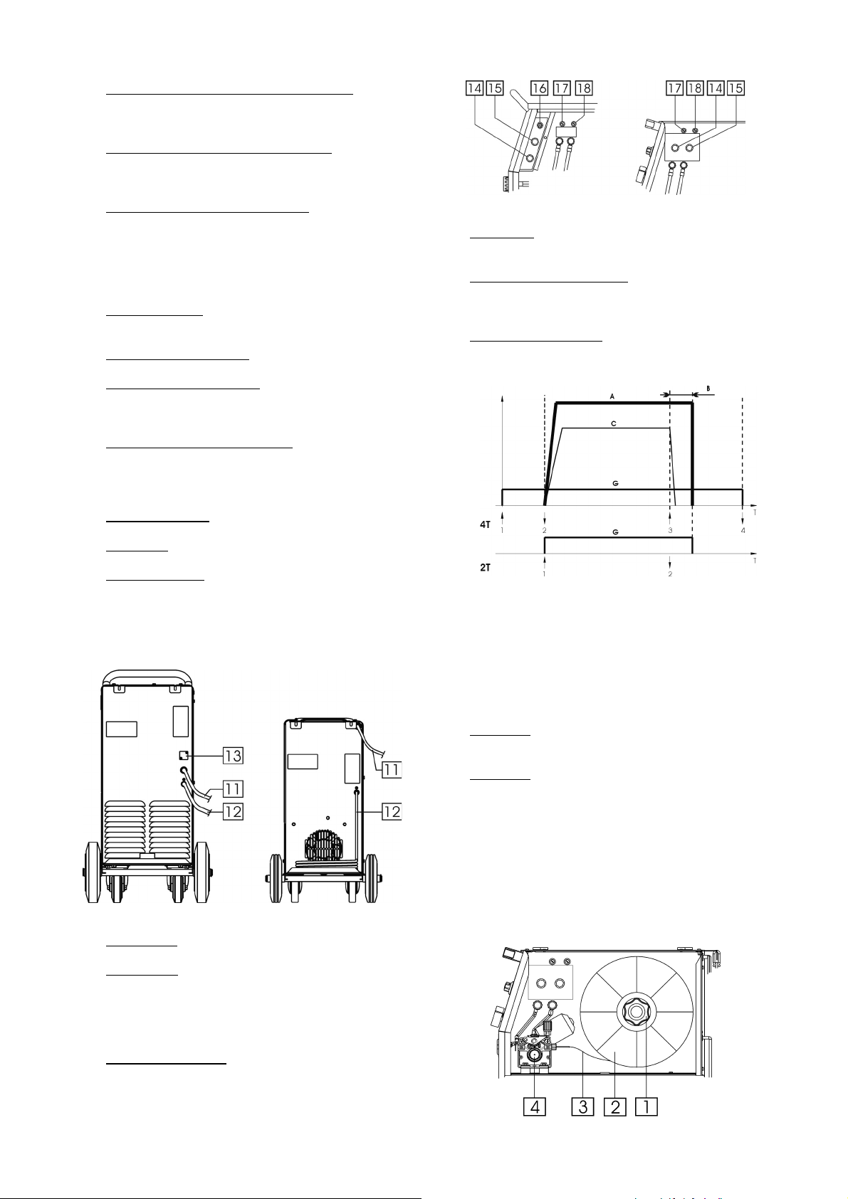
1. Einstellknopf für den Drahtvorschub (WFS):
Ermöglicht die stufenlose Regelung des
Drahtvorschubes im Bereich von 1.0 bis 20m/min.
2. Netz- und Schweißspannungs-Schalter: Mit diesem
Schalter kann die Schweißspannung eingestellt
werden. Die POWERTEC 161C hat 7 Stufen.
3. Thermischer Überhitzungsanzeiger: Diese Lampe
leuchtet auf, wenn die Maschine überhitzt ist und
die Ausgangsleistung abgeschaltet ist. Lassen Sie
die Maschine eingeschaltet. So können die internen
Komponenten abkühlen. Erlischt die Warnleuchte,
kann das Gerät wieder betrieben werden.
4. Schweißbrenner: Führt die Schweißspannung,
Schutzgas und den Schweißdraht.
5. Massekabel mit Klemme.
6. Schweißspannungschalter: Die POWERTEC 191C
hat eine 8 Stufen, die POWERTEC 231C und 271C
hat eine 12 Stufen Schaltung.
7. Hauptschalter und Stromleuchte: Nach Anschluss
an die Stromversorgung und nach Einschalten des
Netzschalters leuchtet diese Lampe auf, um die
Betriebbereitschaft der Maschine anzuzeigen.
8. EURO-Anschluss: Zum Anschluss des Brenners.
9. Anschluss: Werkstückleitung.
10. Digitales Display: Als Option K14044-1 erhältlich
(siehe Abschnitt “Zubehör”). Zeigt
Schweißparameter - Schweißßspannung in [V] und
Schweißstrom in [A]. Nachdem Schweißprozess
wird der durchschnittliche Wert der
Schweißparameter angezeigt.
POWERTEC 191C/231C/271C POWERTEC 161C
14. Punkttimer: Er ermöglicht eine Schweißzeit von 0.2
bis 8 s.
15. Rückbrenn-Zeit-Einstellung: Regelt die Drahtlänge
nach Beendigung der Schweißzeit von 20 bis
250ms.
16. Brennermodusschalter: Hiermit kann man den 2oder 4-Takt-Betrieb wählen. Die Arbeitsweise des
2-/4-Takt-Modus sehen Sie in der Abbildung unten:
Brenner-Taster gedrückt
↑
Brenner-Taster nicht gedrückt
↓
A. Schweißstrom.
B. Rückbrandzeit.
C. WFS.
G. Gas.
POWERTEC 191C/231C/271C POWERTEC 161C
11. Gaschlauch.
12. Primärkabel: Verbinden Sie die Stromquelle mit
dem Eingangskabel, das für diese Maschine
geeignet ist (nur für POWERTEC 191C, 231C und
271C). Dies darf nur von
qualifiziertemFachpersonal durchgeführt werden.
13. Öffnung (abgedeckt): Für CO
K14048-1 (siehe Abschnitt „Zubehör”).
Gas-Vorwärmer
2
17. Sicherung: Diese Sicherung (1A) sichert das PC
Board.
18. Sicherung: Diese Sicherung (4A) sichert den
Drahtvoschubsmotor.
Anbringen der Drahtspule
Drücken Sie die Drahtspule auf den Adapter, so dass die
Spule sich im Uhrzeigersinn dreht, wenn der Draht in
den Drahtvorschubmechanismus eingefädelt wird.
Die Maschine eignet sich für 15kg (300mm) Drahtspulen. Für 5kg (200mm) Drahtspule beigeliegender
Adapter erforderlich.
C-3
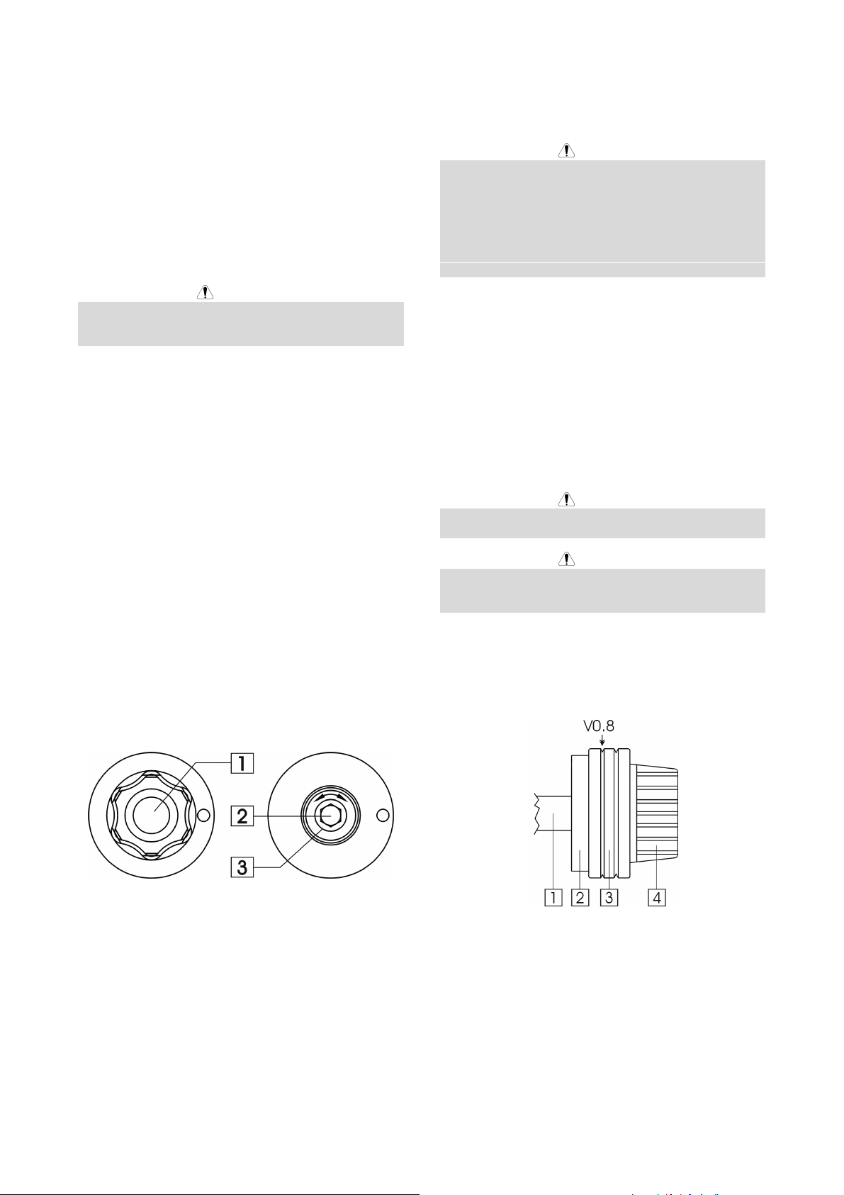
1. Adapter.
2. Drahtspule.
3. Schweißdraht.
4. Drahtvorschubmechanismus.
Stellen Sie sicher, dass der Bolzen auf der SpulenAchse auf die Aussparung der Spule trifft.
Drehen Sie die Spule im Uhrzeigersinn und schneiden
Sie das gebogene Ende ab.
Sorgen Sie dafür, dass kein Grat vorhanden ist.
Einstellung Druck Drahtvorschubrolle
Den Anpressdruck erhöht man durch Drehen im
Uhrzeigersinn und umgekehrt wird er verringert.
WARNUNG
Ist die Drahtspannung zu niedrig, gleitet die
Vorschubrolle über den Draht. Ist die Drahtspannung zu
hoch, besteht die Gefahr, dass der Draht sich verformt.
Dies kann zu Vorschubproblemen im Brenner führen.
Es muss also unbedingt die richtige Spannung
eingestellt werden. Verringern Sie die Spannung, bis die
Rolle anfängt zu gleiten. Drehen Sie dann die
Schrauben einen Schlag im Uhrzeigersinn.
WARNUNG
Reinigen Sie die Drahtführungs-Spirale mit Pressluft
wenn Sie die Drahtspule wechseln, besonders bei
FCAW 1,1mm Innershield-Draht.
Drahtvorschub
Öffnen Sie die Seitenabdeckung.
Nehmen Sie eine Drahtvorschubrolle mit zum Drahtdurchmesser passender Nut.
Setzen Sie die Spule auf die Achse.
Lösen Sie das Drahtende und schneiden Sie das
gebogene Ende ab. Sorgen Sie dafür, dass kein Grat
vorhanden ist.
Führen Sie den Draht in den Drahtvorschub.
Stellen Sie den richtigen Anpressdruck ein.
Bremseneinstellung der Spulen - Achse
Um unkontrolliertes Abrollen des Schweißdrahtes zu
vermeiden, ist die Spulen-Achse mit einer Bremse
ausgestattet.
Eingestellt wird die Bremse mit einer Schraube M10, an
der Innenseite der Achse. Diese Schraube ist sichtbar
nach Entfernung der Befestigungsschraube der SpulenAchse.
Inserting Einfädeln des Drahtes in den
Schweiß-Brenner
Entfernen Sie die Gasdüse und die Kontaktdüse vom
Brenner.
Bringen Sie den Drahtgeschwindigkeitsknopf in die
Mittelposition.
Nach dem Einschalten der Maschine auf “ON” drücken
und halten Sie den Brennertaster solange, bis der
Schweißdraht aus der Stromkontaktdüse des Brenners
läuft.
WARNUNG
Halten Sie das Brennerende in sicherer Entfernung von
Augen und Händen, während der Draht zugeführt wird.
WARNUNG
Wenn ausreichend Draht aus der Maschine austritt,
schalten Sie diese ab, bevor Sie die Gasdüse und die
Kontaktdüse wieder aufsetzen.
Montieren der Drahtvorschubrolle
Standardmäßig ist die Maschine ausgerüstet mit einer
Drahtvorschubrolle V0.8/V1.0 mm. Die Abbildung unten
zeigt das Montieren der Drahtvorschubrolle für 0.8 mm
Massiv-Draht.
1. Befestigungsschraube.
2. Einstellschraube M10.
3. Druckfeder.
Der Federdruck nimmt zu, wenn die Schraube im
Uhrzeigersinn gedreht wird. Die Bremskraft nimmt dann
auch zu.
Wenn Sie die Schraube gegen den Uhrzeiger drehen,
nehmen der Federdruck und die Bremskraft ab.
Nach dem Einstellen kann man die Befestigungsschraube wieder anbringen.
1. Motor-Achse.
2. Montagering.
3. Drahtvorschubrolle.
4. Kappe.
Entfernen der Drahtvorschubrolle:
• Druckhebel des Drahtvorschubes entspannen.
• Schraubkappe entfernen.
• Vorschubrolle vom Montagering abnehmen.
Montieren der Drahtvorschubrolle:
• Drahtvorschubrolle auf den Montagering festsetzen.
C-4
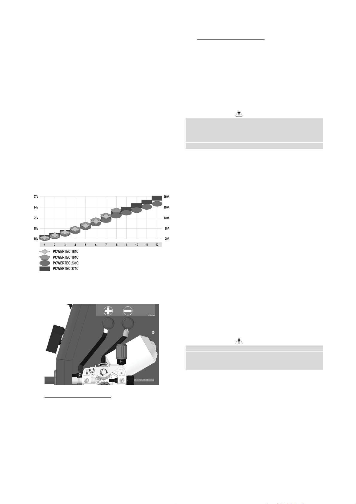
• Schraubkappe auf den Montagering festsetzen.
• Draht einfädeln.
• Druckhebel setzen.
Gas-Versorgung
Stellen Sie die Gasflasche auf den Flaschenträger und
sichern Sie die Flasche mit der Kette.
Entfernen Sie die Sicherungskappe von der Gasflasche
und schließen Sie den Druckminderer an.
Verbinden Sie den Gasschlauch der Maschine mit dem
Druckminderer.
MAG-Schweißen
Bevor Sie mit dem Schweißen beginnen:
• Eingangsstromkabel anschließen.
• Schalten Sie die Maschine ein mit dem
“Hauptschalter”.
• Drahteinfädeln mit.
• Stellen Sie die Drahtvorschubgeschwindigkeit und
Schweißspannung entsprechend der Schweißaufgabe ein. Die unten aufgeführte Darstellung
kann Ihnen bei Einstellungen behilflich sein:
2. Für negative Polarität (DC -):
• Schließen Sie den Brenner an den negativen (-)
Schweißausgang an.
• Verbinden Sie das Massekabel mit dem
positiven (+) Anschluß.
Dies ist die typische Konfiguration für die meisten
Innershield Drähte (Flux Cored Arc Welding SelfShielded / FCAW-S).
Wartung
WARNUNG
Für Wartung und Reparatur des Gerätes konsultieren
Sie bitte Ihren Fachhändler oder die Lincoln Electric.
Eine unsachgemäß durchgeführte Wartung oder
Reparatur durch eine nicht qualifizierte Person führt zum
Erlöschen der Garantie.
Die Wartungsintervalle können abhängig von den
Arbeitsbedingungen der Maschine schwanken.
Ein schwerwiegender Schaden ist unverzüglich zu
melden.
Laufende Wartung (täglich)
• Überprüfen der Kabel und aller Anschlüsse.
Ersetzen Sie diese, wenn erforderlich.
• Entfernen Sie Schweißspritzer von der Schweiß-
düse. Schweißspritzer können den Fluß des
Schutzgases von der Schweißdüse zum Lichtbogen
beeinflussen.
• Überprüfen Sie den Zustand der Düse und ersetzen
Sie diese, wenn erforderlich.
• Überprüfen Sie Zustand und Betrieb des Lüfters –
halten Sie dessen Lüftungsschlitze frei und sauber.
• Die Maschine ist nun schweißbereit.
Wechseln der Polarität
1. Für positive Polarität (DC +):
• Schließen Sie den Brenner an den positiven (+)
Schweißausgang an.
• Verbinden Sie das Massekabel mit dem
negativen (-) Anschluß.
Dies ist die typische Konfiguration für das MetalSchutzgas-Schweißen (MIG).
Periodische Wartung (alle 20 Betriebsstunden,
mindestens einmal im Jahr)
Zusätzlich zur laufenden Wartung sind folg. Arbeiten
durchzuführen:
• Halten Sie die Maschine sauber. Verwenden Sie
einen trockenen Luftstrom mit geringem Luftdruck.
Entfernen Sie den Staub von der äußeren Abdeckung und aus dem Innern des Gehäuses.
• Überprüfen Sie alle Schrauben auf festen Sitz und
ziehen Sie diese nach, wenn erforderlich.
WARNUNG
Die Maschine muß während der Durchführung der
Wartungsarbeiten vom Netz getrennt sein. Nach jeder
Reparatur sind geeignete Tests durchzuführen, um die
Betriebssicherheit zu überprüfen.
C-5

Elektromagnetische Verträglichkeit (EMC)
Diese Maschine wurde unter Beachtung aller zugehörigen Normen und Vorschriften gebaut. Dennoch kann es unter
besonderen Umständen zu elektromagnetischen Störungen anderer elektronischer Syteme (z.B. Telefon, Radio, TV,
Computer usw.) kommen. Diese Störungen können im Extremfall zu Sicherheitsproblemen der beeinflussten Systeme
führen. Lesen Sie deshalb diesen Abschnitt aufmerksam durch, um das Auftreten elektromagnetischer Störungen zu
reduzieren oder ganz zu vermeiden.
Diese Maschine ist für den industriellen Einsatz konzipiert worden. Bei Benutzung dieser Anlage in
Wohngebieten sind daher besondere Vorkehrungen zu treffen, um Störungen durch elektromagnetische
Beeinflussungen zu vermeiden. Halten Sie sich stets genau an die in dieser Bedienungsanleitung
genannten Einsatzvorschriften. Falls dennoch elektromagnetische Störungen auftreten, müssen geeignete
Gegenmaßnahmen getroffen werden. Kontaktieren Sie gegebenenfalls den Kundendienst der Lincoln Electric.
Technische Änderungen der Anlage sind nur nach schriftlicher Genehmigung des Herstellers zulässig.
Vergewissern Sie sich vor der Inbetriebnahme des Schweißgerätes, dass sich keine für elektromagnetische Störungen
empfänglichen Geräte und Anlagen im möglichen Einflussbereich befinden. Dies gilt besonders für:
• Steuerleitungen, Datenkabel und Telefonleitungen.
• Radio und Televisions-Sender oder -Empfänger sowie deren Kabelverbindungen. Computer oder
computergesteuerte Anlagen.
• Elektronische Sicherheitseinrichtungen und Steuereinheiten für industrielle Anlagen. Elektronische Mess- und
Kalibriereinrichtungen.
• Medizinische Apparate und Geräte, Hörgeräte oder persönliche Implantate wie Herzschrittmacher usw. Achtung!
Informieren Sie sich vor Inbetriebnahme der Anlage in der Nähe von Kliniken und Krankenhäusern über die hierzu
gültigen Vorschriften, und sorgen Sie für die exakte Einhaltung aller erforderlichen Sicherheitsmaßnahmen!
• Prüfen Sie grundsätzlich die elektromagnetische Verträglichkeit von Geräten, die sich im Einflussbereich der
Schweißanlage befinden.
• Dieser Einflussbereich kann in Abhängigkeit der physikalischen Umstände in seiner räumlichen Ausdehnung stark
variieren.
11/04
Befolgen Sie zusätzlich die folgenden Richtlinien um elektromagnetische Abstrahlungen zu reduzieren:
• Schließen Sie die Maschine stets nur wie beschrieben an. Falls dennoch Störungen auftreten, muss eventuell ein
zusätzlicher Netzfilter eingebaut werden.
• Halten Sie die Länge der Schweißkabel möglichst auf ein erforderliches Mindestmaß begrenzt. Wenn möglich,
sollte das Werkstück separat geerdet werden. Beachten Sie stets bei allen Maßnahmen, dass hierdurch keinerlei
Gefährdung von direkt oder indirekt beteiligten Menschen verursacht wird.
• Abgeschirmte Kabel im Arbeitsbereich können die elektromagnetische Abstrahlung reduzieren. Dies kann je nach
Anwendung notwendig sein.
C-6

Technische Daten
POWERTEC 161C, 191C, 231C & 271C
Netzeingangsspannung
230V ± 10%
Einphasig
LEISTUNGDATEN BEI 40°C UMGEBUNGSTEMPERATUR
Einschaltdauer
(basierend auf 10min-Zyklus)
161C:
20%
60%
100%
161C:
191C:
231C:
271C:
NETZEINGANG
Leistungsaufnahme
6.0 kVA @ 20% ED
8.2 kVA @ 20% ED
10.6 kVA @ 20% ED
Frequenz
50/60 Hz
12.9 kVA @ 20% ED
Ausgangsstromstärke Ausgangsspannung
150A
87A
70A
21.5 Vdc
18.7 Vdc
17.5 Vdc
191C:
231C:
271C:
161C:
191C:
231C:
271C:
161C:
191C:
231C:
271C:
161C:
191C:
231C:
271C:
20%
60%
100%
20%
60%
100%
20%
60%
100%
180A
105A
80A
220A
130A
100A
255A
150A
120A
AUSGANGSLEISTUNG
Schweißstrombereich Maximale Leerlaufspannung
30A - 150A
30A - 180A
30A - 220A
30A - 255A
161C:
191C:
231C:
271C:
37 Vdc
42 Vdc
45 Vdc
47 Vdc
PRIMÄRKABELQUERSCHNITTE UND ABSICHERUNG
Sicherung oder Sicherungsautomat Primärkabel
16A träge
20A träge
25A träge
32A träge
161C:
191C:
231C:
271C:
3 Adern, 1.5mm
3 Adern, 2.5mm
3 Adern, 2.5mm
3 Adern, 4.0mm
ABMESSUNGEN UND GEWICHT
Höhe Breite Länge Gewicht
615 mm 390 mm 825 mm 53 kg
765 mm 427 mm 850 mm 70 kg
765 mm 427 mm 850 mm 80 kg
765 mm 427 mm 850 mm 83 kg
Zulässige Umgebungstemperaturen
-10°C bis +40°C
Zulässige Lagerungstemperaturen
-25°C bis +55°C
23.0 Vdc
19.3 Vdc
18.0 Vdc
25.0 Vdc
20.5 Vdc
19.0 Vdc
26.8 Vdc
21.5 Vdc
20.0 Vdc
2
2
2
2
C-7
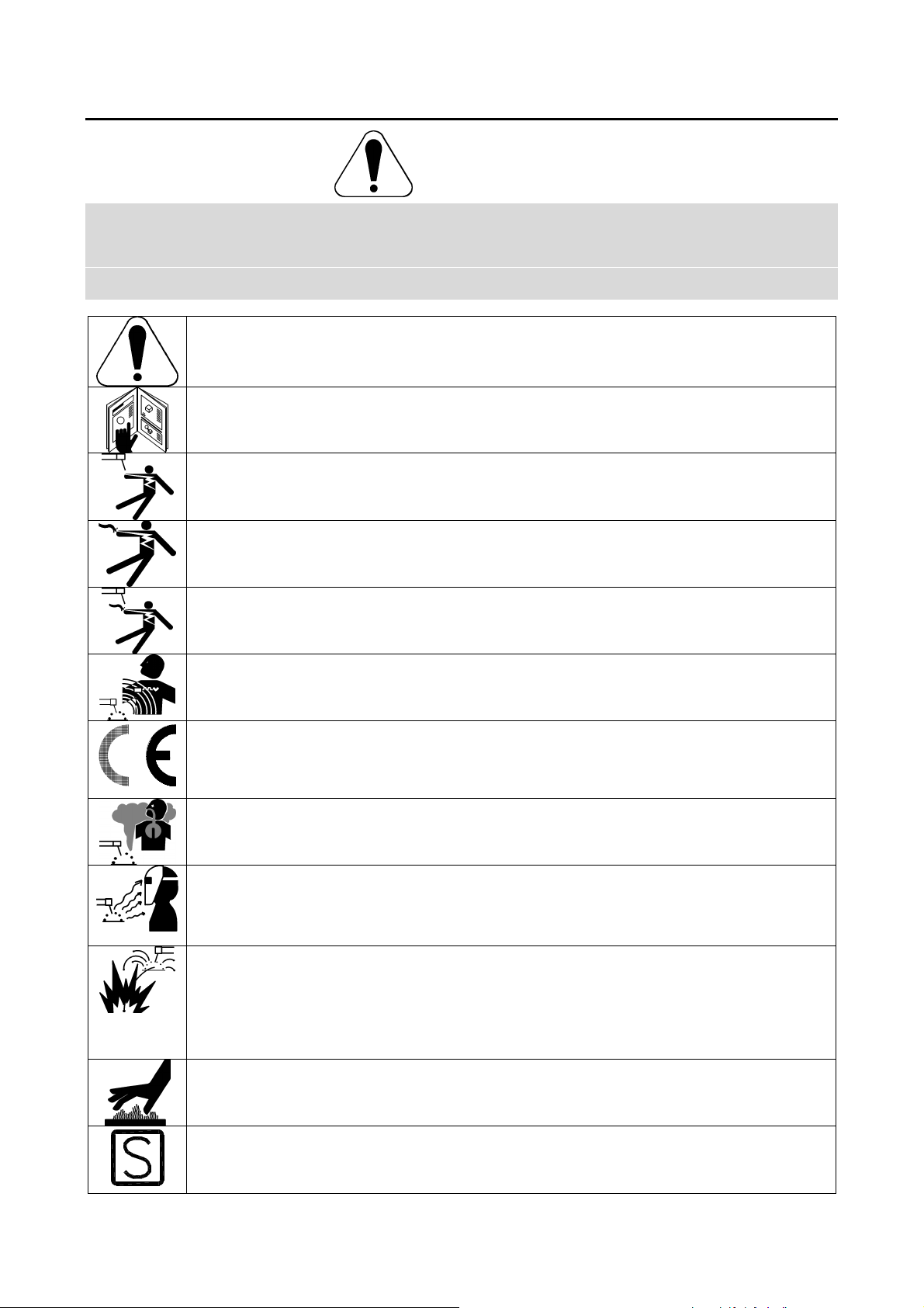
Seguridad
11/04
ATENCION
Este equipo debe ser utilizado por personal cualificado. Asegúrese de que todos los procedimientos de instalación,
funcionamiento, mantenimiento y reparación son realizados únicamente por personal cualificado. Lea y comprenda este
manual antes de trabajar con el equipo. No seguir las instrucciones que se indican en este manual podría provocar
lesiones personales de distinta gravedad, incluída la muerte o daños a este equipo. Lea y comprenda las explicaciones
de los símbolos de advertencia, que se muestran a continuación. Lincoln Electric no se hace responsable de los daños
producidos por una instalación incorrecta, una falta de cuidado o un funcionamiento inadecuado.
¡PELIGRO!: Este símbolo indica qué medidas de seguridad se deben tomar para evitar lesiones
personales de diferente gravedad, incluída la muerte, o daños a este equipo. Protéjase usted y a los
demás contra posibles lesiones personales de distinta gravedad, incluída la muerte.
LEA Y COMPRENDA LAS INSTRUCCIONES: Asimile el contenido de este manual de instrucciones
antes de trabajar con el equipo. La soldadura al arco puede ser peligrosa. NO seguir las
instrucciones que se indican en este manual podría provocar lesiones personales de distinta
gravedad, incluída la muerte, o daños a este equipo.
LA DESCARGA ELECTRICA PUEDE MATAR: Los equipos de soldadura generan voltajes elevados.
No toque el electrodo, la pinza de masa, o las piezas a soldar cuando el equipo esté en marcha.
Aíslese del electrodo, la pinza de masa, o las piezas en contacto cuando el equipo esté en marcha.
EQUIPOS ELÉCTRICOS: Desconecte la alimentación del equipo desde el interruptor de red o desde
la caja de fusibles antes de reparar o manipular el interior de este equipo. Conecte el tierra de este
equipo de acuerdo con el reglamento eléctrico local.
EQUIPOS ELÉCTRICOS: Inspeccione con regularidad los cables de red, electrodo y masa. Si hay
algún daño en el aislamiento sustituya dicho cable inmediatamente. No coloque directamente la
pinza portaelectrodos sobre la mesa de soldadura o sobre cualquier otra superficie que esté en
contacto con la pinza de masa para evitar el riesgo de un cebado accidental del arco.
LOS CAMPOS ELÉCTRICOS Y MAGNÉTICOS PUEDEN SER PELIGROSOS: La corriente eléctrica
que circula a través de un conductor origina campos eléctricos y magnéticos (EMF) localizados. Los
campos EMF pueden interferir con los marcapasos, las personas que utilicen estos dispositivos
deben consultar a su médico antes de acercarse a una máquina de soldar.
CUMPLIMIENTO CE: Este equipo cumple las directivas de la CEE.
LOS HUMOS Y LOS GASES PUEDEN SER PELIGROSOS: La soldadura puede producir humos y
gases peligrosos para la salud. Evite respirarlos. Utilice la suficiente ventilación y/o extracción de
humos para mantener los humos y gases alejados de la zona de respiración.
LA LUZ DEL ARCO PUEDE QUEMAR: Utilice una pantalla de protección con el filtro adecuado para
proteger sus ojos de la luz y de las chispas del arco cuando se suelde o se observe una soldadura
por arco abierto. Use ropa adecuada de material ignífugo para proteger la piel de las radiaciones del
arco. Proteja a otras personas que se encuentren cerca del arco y/o adviértales que no miren
directamente al arco ni se expongan a su luz o sus proyecciones.
LAS PROYECCIONES DE SOLDADURA PUEDEN PROVOCAR UN INCENDIO O UNA
EXPLOSIÓN: Retire del lugar de soldadura todos los objetos que presenten riesgo de incendio.
Tenga un extintor de incendios siempre a mano. Recuerde que las chispas y las proyecciones
calientes de la soldadura pueden pasar fácilmente por aberturas pequeñas. No caliente, corte o
suelde tanques, tambores o contenedores hasta haber tomado las medidas necesarias para asegurar
que tales procedimientos no van a producir vapores inflamables o tóxicos. No utilice nunca este
equipo cuando haya presente gases inflamables, vapores o líquidos combustibles.
LA SOLDADURA PUEDE QUEMAR: La soldadura genera una gran cantidad de calor. Las
superficies calientes y los materiales en el área de trabajo pueden provocar quemaduras graves.
Utilice guantes y pinzas para tocar o mover los materiales que haya en el área de trabajo.
MARCAJE SEGURIDAD: Este equipo es adecuado como fuente de potencia para operaciones de
soldadura efectuadas en un ambiente con alto riesgo de descarga eléctrica.
D-1
 Loading...