

Lincoln Electric NR-203MP, NR-232, NR-202, NR-211-MP, NR-203 Nickel (1%) Welding Instruction Manual
...Page 1
INNERSHIELD
®
ELECTRODES
Welding Guide
Page 2

– 2 –
TABLE OF CONTENTS
SAFETY PRECAUTIONS ..........................3-11
INTRODUCTION...........................................12
PRODUCT ADVANTAGES.......................13-15
RECOMMENDED EQUIPMENT.......................15
WELDING PREPARATIONS........................16-17
Choose the Proper Innershield Gun............................16
Prepare the Work.........................................................17
Optimizing Feeding......................................................17
WELDING TECHNIQUES..............................18-24
Set the CTWD..............................................................18
Set the Wire Feed Speed (WFS).................................19
Start the Arc.................................................................19
Set the Voltage............................................................19
Travel Speed ...............................................................19
Loading 13-14 Lb. Coils on a 2” Spindle......................20
Handling Poor Fitup.....................................................21
Use the Proper Drag Angle..........................................21
Use the Proper Wire Angle to Joint .............................21
Making Vertical Up Welds ......................................22-23
Making Downhill and Vertical Down Welds .................23
Working with NS-3M....................................................24
OPERATING GUIDE.......................................25-29
Troubleshooting......................................................25-26
Effect of Operating Variables..................................26-27
Welder Qualification Test.............................................27
Storing Innershield Electrode .................................28-29
WELDING PROCEDURES...............................30-39
OPERA TING PROCEDURES..........................40-45
INNERSHIELD GUN P ARTS............................46-47
LINCOLN WELDING SCHOOL.......................48-49
Page 3
WARNING
The serviceability of a product or structure utilizing this
type of information is and must be the sole responsibility
of the builder/user. Many variables beyond the control of
The Lincoln Electric Company affect the results obtained
in applying this type of information. These variables
include, but are not limited to, welding procedure, plate
chemistry and temperature, weldment design, fabrication
methods and service requirements.
CALIFORNIA PROPOSITION 65 WARNINGS
ARC WELDING CAN BE HAZARDOUS. PROTECT YOURSELF AND
OTHERS FROM POSSIBLE SERIOUS INJURY OR DEATH. KEEP
CHILDREN AWAY. PACEMAKER WEARERS SHOULD CONSULT WITH
THEIR DOCTOR BEFORE OPERATING.
Read and understand the following safety highlights. For
additional safety information, it is strongly recommended that
you purchase a copy of “Safety in Welding & Cutting - ANSI
Standard Z49.1” from the American Welding Society, P.O. Box
351040, Miami, Florida 33135 or CSA Standard W117.2-1974.
A Free copy of “Arc Welding Safety” booklet E205 is available
from the Lincoln Electric Company, 22801 St. Clair Avenue,
Cleveland, Ohio 44117-1199.
BE SURE THAT ALL INSTALLATION, OPERATION,
MAINTENANCE AND REPAIR PROCEDURES ARE
PERFORMED ONLY BY QUALIFIED INDIVIDUALS.
Mar ‘95
Diesel engine exhaust and some of its constituents are known
to the State of California to cause cancer, birth defects, and
other reproductive harm.
The engine exhaust from this product contains chemicals
known to the State of California to cause cancer, birth defects,
or other reproductive harm.
The Above For Diesel Engines
The
Above For Gasoline
Engines
-SAFETY-
– 3 –
Page 4
FOR ENGINE
powered equipment.
1.a. Turn the engine off before troubleshooting and maintenance
work unless the maintenance work requires it to be running.
_____________________________________________
1.b. Operate engines in open, well-ventilated
areas or vent the engine exhaust fumes
outdoors.
1.c. Do not add the fuel near an open flame
welding arc or when the engine is running.
Stop the engine and allow it to cool before
refueling to prevent spilled fuel from
vaporizing on contact with hot engine parts
and igniting. Do not spill fuel when filling
tank. If fuel is spilled, wipe it up and do not
start engine until fumes have been
eliminated.
____________________________________________________
1.d. Keep all equipment safety guards, covers and devices in
position and in good repair.Keep hands, hair, clothing and
tools away from V-belts, gears, fans and all other moving
parts when starting, operating or repairing equipment.
____________________________________________________
1.e. In some cases it may be necessary to remove safety
guards to perform required maintenance. Remove
guards only when necessary and replace them when the
maintenance requiring their removal is complete.
Always use the greatest care when working near moving
parts.
___________________________________________________
1.f. Do not put your hands near the engine fan.
Do not attempt to override the governor or
idler by pushing on the throttle control rods
while the engine is running.
___________________________________________________
1.g. To prevent accidentally starting gasoline engines while
turning the engine or welding generator during maintenance
work, disconnect the spark plug wires, distributor cap or
magneto wire as appropriate.
______________________________________
1.h. To avoid scalding, do not remove the
radiator pressure cap when the engine is
hot.
– 4 –
Page 5
ELECTRIC AND
MAGNETIC FIELDS
may be dangerous
2.a. Electric current flowing through any conductor causes
localized Electric and Magnetic Fields (EMF). Welding
current creates EMF fields around welding cables and
welding machines
2.b. EMF fields may interfere with some pacemakers, and
welders having a pacemaker should consult their physician
before welding.
2.c. Exposure to EMF fields in welding may have other health
effects which are now not known.
2.d. All welders should use the following procedures in order to
minimize exposure to EMF fields from the welding circuit:
2.d.1.
Route the electrode and work cables together - Secure
them with tape when possible.
2.d.2. Never coil the electrode lead around your body.
2.d.3. Do not place your body between the electrode and
work cables. If the electrode cable is on your right
side, the work cable should also be on your right side.
2.d.4. Connect the work cable to the workpiece as close as
possible to the area being welded.
2.d.5. Do not work next to welding power source.
ELECTRIC SHOCK can
kill.
3.a. The electrode and work (or ground) circuits
are electrically “hot” when the welder is on.
Do not touch these “hot” parts with your bare
skin or wet clothing. Wear dry, hole-free
gloves to insulate hands.
3.b. Insulate yourself from work and ground using dry insulation.
Make certain the insulation is large enough to cover your full
area of physical contact with work and ground.
In addition to the normal safety precautions, if welding
must be performed under electrically hazardous
conditions (in damp locations or while wearing wet
clothing; on metal structures such as floors, gratings or
scaffolds; when in cramped positions such as sitting,
(Cont’d on page 5)
– 5 –
Page 6
ELECTRIC SHOCK can kill. (Cont’d)
kneeling or lying, if there is a high risk of unavoidable or
accidental contact with the workpiece or ground) use
the following equipment:
• Semiautomatic DC Constant Voltage (Wire) Welder.
• DC Manual (Stick) Welder.
• AC Welder with Reduced Voltage Control.
3.c. In semiautomatic or automatic wire welding, the electrode,
electrode reel, welding head, nozzle or semiautomatic
welding gun are also electrically “hot”.
3.d. Always be sure the work cable makes a good electrical
connection with the metal being welded. The connection
should be as close as possible to the area being welded.
3.e. Ground the work or metal to be welded to a good electrical
(earth) ground.
3.f.
Maintain the electrode holder, work clamp, welding cable and
welding machine in good, safe operating condition. Replace
damaged insulation.
3.g. Never dip the electrode in water for cooling.
3.h. Never simultaneously touch electrically “hot” parts of
electrode holders connected to two welders because voltage
between the two can be the total of the open circuit voltage
of both welders.
3.i. When working above floor level, use a safety belt to protect
yourself from a fall should you get a shock.
3.j. Also see Items 6.c. and 8.
ARC RAYS can burn.
4.a. Use a shield with the proper filter and cover
plates to protect your eyes from sparks and
the rays of the arc when welding or observing
open arc welding. Headshield and filter lens
should conform to ANSI Z87. I standards.
4.b. Use suitable clothing made from durable flame-resistant
material to protect your skin and that of your helpers from
the arc rays.
4.c. Protect other nearby personnel with suitable, non-flammable
screening and/or warn them not to watch the arc nor expose
themselves to the arc rays or to hot spatter or metal.
– 6 –
Page 7
FUMES AND GASES
can be dangerous.
5.a.Welding may produce fumes and gases
hazardous to health. Avoid breathing these
fumes and gases.When welding, keep
your head out of the fume. Use enough
ventilation and/or exhaust at the arc to keep
fumes and gases away from the breathing zone. When
welding with electrodes which require special
ventilation such as stainless or hard facing (see
instructions on container or MSDS) or on lead or
cadmium plated steel and other metals or coatings
which produce highly toxic fumes, keep exposure as
low as possible and below Threshold Limit Values (TLV)
using local exhaust or mechanical ventilation. In
confined spaces or in some circumstances, outdoors, a
respirator may be required. Additional precautions are
also required when welding on galvanized steel.
5.b.
Do not weld in locations near chlorinated hydrocarbon
vapors
coming from degreasing, cleaning or spraying operations.
The heat and rays of the arc can react with solvent vapors
to
form phosgene, a highly toxic gas, and other irritating
products.
5.c. Shielding gases used for arc welding can displace air and
cause injury or death. Always use enough ventilation,
especially in confined areas, to insure breathing air is safe.
5.d. Read and understand the manufacturer’s instructions for this
equipment and the consumables to be used, including the
material safety data sheet (MSDS) and follow your
employer’s safety practices. MSDS forms are available from
your welding distributor or from the manufacturer.
5.e. Also see item 1.b.
WELDING SPARKS can
cause fire or explosion.
6.a.
Remove fire hazards from the welding area.
If this is not possible, cover them to prevent
the welding sparks from starting a fire.
Remember that welding sparks and hot
materials from welding can easily go through small cracks
and openings to adjacent areas. Avoid welding near
hydraulic lines. Have a fire extinguisher readily available.
6.b. Where compressed gases are to be used at the job site,
special precautions should be used to prevent hazardous
situations. Refer to “Safety in Welding and Cutting” (ANSI
Standard Z49.1) and the operating information for the
equipment being used.
– 7 –
Page 8

WELDING SPARKS can cause fire
or explosion.
(Cont’d)
6.c. When not welding, make certain no part of the electrode
circuit is touching the work or ground. Accidental contact
can cause overheating and create a fire hazard.
6.d. Do not heat, cut or weld tanks, drums or containers until the
proper steps have been taken to insure that such procedures
will not cause flammable or toxic vapors from substances
inside. They can cause an explosion even
though
they have
been “cleaned”. For information, purchase “Recommended
Safe Practices for the
Preparation
for Welding and Cutting of
Containers and Piping That Have Held Hazardous
Substances”, AWS F4.1 from the American Welding Society
(see address above).
6.e. Vent hollow castings or containers before heating, cutting or
welding. They may explode.
6.f.
Sparks and spatter are thrown from the welding arc. Wear oil
free protective garments such as leather gloves, heavy shirt,
cuffless trousers, high shoes and a cap over your hair. Wear
ear plugs when welding out of position or in confined places.
Always wear safety glasses with side shields when in a
welding area.
6.g. Connect the work cable to the work as close to the welding
area as practical. Work cables connected to the building
framework or other locations away from the welding area
increase the possibility of the welding current passing
through lifting chains, crane cables or other alternate
circuits. This can create fire hazards or overheat lifting
chains or cables until they fail.
6.h. Also see item 1.c.
CYLINDER may explode
if damaged.
7.a. Use only compressed gas cylinders
containing the correct shielding gas for the
process used and properly operating
regulators designed for the gas and
pressure used. All hoses, fittings, etc. should be suitable for
the application and maintained in good condition.
7.b. Always keep cylinders in an upright position securely
chained to an undercarriage or fixed support.
7.c. Cylinders should be located:
•Away from areas where they may be struck or subjected to
physical damage.
• A safe distance from arc welding or cutting operations and
any other source of heat, sparks, or flame.
– 8 –
Page 9

CYLINDER may explode if
damaged. (Cont’d)
7.d. Never allow the electrode, electrode holder or any other
electrically “hot” parts to touch a cylinder.
7.e. Keep your head and face away from the cylinder valve outlet
when opening the cylinder valve.
7.f. Valve protection caps should always be in place and hand
tight except when the cylinder is in use or connected for
use.
7.g. Read and follow the instructions on compressed gas
cylinders, associated equipment, and CGA publication P-l,
“Precautions for Safe Handling of Compressed Gases in
Cylinders,” available from the Compressed Gas Association
1235 Jefferson Davis Highway, Arlington, VA 22202.
FOR ELECTRICALLY
powered equipment.
8.a. Turn off input power using the disconnect
switch at the fuse box before working on
the equipment.
8.b. Install equipment in accordance with the U.S. National
Electrical Code, all local codes and the manufacturer’s
recommendations.
8.c. Ground the equipment in accordance with the U.S. National
Electrical Code and the manufacturer’s recommendations.
PRÉCAUTIONS DE SÛRETÉ
Pour
votre propre protection lire et observer toutes les instructions
et les précautions de sûreté specifiques qui parraissent dans ce
manuel aussi bien que les précautions de sûreté générales
suivantes:
Sûreté Pour Soudage A L’Arc
1. Protegez-vous contre la secousse électrique:
a. Les circuits à l’électrode et à la piéce sont sous tension
quand la machine à souder est en marche. Eviter toujours
tout contact entre les parties sous tension et la peau nue
ou les vétements mouillés. Porter des gants secs et sans
trous pour isoler les mains.
– 9 –
Page 10

b. Faire trés attention de bien s’isoler de la masse quand on
soude dans des endroits humides, ou sur un plancher
metallique ou des grilles metalliques, principalement dans
les positions assis ou couché pour lesquelles une grande
partie du corps peut être en contact avec la masse.
c. Maintenir le porte-électrode, la pince de masse, le câble de
soudage et la machine à souder en bon et sûr état
defonctionnement.
d. Ne jamais plonger le porte-électrode dans l’eau pour le
refroidir.
e. Ne jamais toucher simultanément les parties sous tension
des porte-électrodes connectés à deux machines à souder
parce que la tension entre les deux pinces peut être le total
de la tension à vide des deux machines.
f. Si on utilise la machine à souder comme une source de
courant pour soudage semi-automatique, ces precautions
pour le porte-électrode s’applicuent aussi au pistolet de
soudage.
2. Dans le cas de travail au dessus du niveau du sol, se protéger
contre les chutes dans le cas ou on recoit un choc. Ne jamais
enrouler le câble-électrode autour de n’importe quelle partie du
corps.
3. Un coup d’arc peut être plus sévère qu’un coup de soliel, donc:
a. Utiliser un bon masque avec un verre filtrant approprié ainsi
qu’un verre blanc afin de se protéger les yeux du
rayonnement de l’arc et des projections quand on soude ou
quand on regarde l’arc.
b. Porter des vêtements convenables afin de protéger la peau
de soudeur et des aides contre le rayonnement de l‘arc.
c. Protéger l’autre personnel travaillant à proximité au soudage
à l’aide d’écrans appropriés et non-inflammables.
4. Des gouttes de laitier en fusion sont émises de l’arc de soudage.
Se protéger avec des vêtements de protection libres de l’huile,
tels que les gants en cuir, chemise épaisse, pantalons sans
revers, et chaussures montantes.
5. Toujours porter des lunettes de sécurité dans la zone de
soudage. Utiliser des lunettes avec écrans lateraux dans les
zones où l’on pique le laitier.
6. Eloigner les matériaux inflammables ou les recouvrir afin de
prévenir tout risque d’incendie dû aux étincelles.
– 10 –
Page 11

7. Quand on ne soud
e pas, poser la pince à une endroit isolé de
la masse. Un court-circuit accidental peut provoquer un
échauffement et un risque d’incendie.
8. S’assurer que la masse est connectée le plus prés possible
de la zone de travail qu’il est pratique de le faire. Si on place
la masse sur la charpente de la construction ou d’autres
endroits éloignés de la zone de travail, on augmente le risque
de voir passer le courant de soudage par les chaines de
levage, câbles de grue, ou autres circuits. Cela peut
provoquer des risques d’incendie ou d’echauffement des
chaines et des câbles jusqu’à ce qu’ils se rompent.
9. Assurer une ventilation suffisante dans la zone de soudage.
Ceci est particuliérement important pour le soudage de tôles
galvanisées plombées, ou cadmiées ou tout autre métal qui
produit des fumeés toxiques.
10. Ne pas souder en présence de vapeurs de chlore provenant
d’opérations de dégraissage, nettoyage ou pistolage. La
chaleur ou les rayons de l’arc peuvent réagir avec les vapeurs
du solvant pour produire du phosgéne (gas fortement toxique)
ou autres produits irritants.
11. Pour obtenir de plus amples renseignements sur la sûreté,
voir le code “Code for safety in welding and cutting” CSA
Standard W 117.2-1974.
PRÉCAUTIONS DE SÛRETÉ POUR
LES MACHINES À SOUDER À
TRANSFORMATEUR ET À
REDRESSEUR
1. Relier à la terre le chassis du poste conformement au code de
l’électricité et aux recommendations du fabricant. Le dispositif
de montage ou la piece à souder doit être branché à une
bonne mise à la terre.
2. Autant que possible, I’installation et l’entretien du poste seront
effectués par un électricien qualifié.
3. Avant de faires des travaux à l’interieur de poste, la
debrancher à l’interrupteur à la boite de fusibles.
4. Garder tous les couvercles et dispositifs de sûreté à leur
place.
– 11 –
Page 12
– 12 –
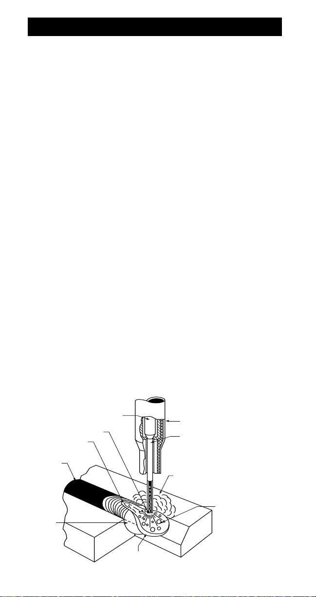
INNERSHIELD®
Innershield is an arc welding process that uses a continuously fed
wire to supply filler metal to the arc. The wire is not solid, but is
tubular. Agents necessary to shield the arc from the surrounding
atmosphere are placed inside the tube. No additional shielding is
required. Innershield was originally used as a replacement for stick
welding. Innershield can provide higher productivity and enhance
quality when compared to stick welding. It offers increased arc-on
time due to the continuous nature of the process. There are also
fewer starts and stops, which are frequent sources for defects.
Although the Innershield process has been displaced in many
areas by gas-shielded processes, Innershield continues to be an
important process for steel fabrication in many markets.
Innershield is the primary means for structural steel building
erection in the United States. In any shop or shipyard where wind
is a problem, Innershield can be a viable solution. Pipeline
fabrication is often done with Innershield because it is done
outdoors and shielding gas is sometimes difficult to get to these
locations.
Lincoln Electric, the originator of the Innershield process, makes
Innershield wire in a proprietary manner. The manufacturing
processes that Lincoln Electric uses has specific benefits that you
can see in every pound of wire you use. The Innershield wires
Lincoln Electric produces are very stiff and have excellent column
strength. This allows for excellent feedability. Lincoln Electric also
fills the wire in a proprietary manner. This step ensures that you get
the right amount of fill in every inch of wire. Lincoln Electric is the
worldwide leader in Innershield. You can see that when you use
our products, meet with our sales reps, or call the factory for
support.
w
INTRODUCTION
Current carrying
contact tip
Arc
Molten slag
Solidified
slag
Solidified
eld
metal
Molten
weld metal
Insulated Guide
Wire core consists of
powdered metal, vapor
(or gas) forming materials,
deoxidizers and scavengers.
Arc shield composed of
vaporized and slag forming
compounds protects metal
transferring through arc.
Metal
droplets
covered with
a thin slag
coating,
forming
molten puddle.
Page 13

– 13 –
INNERSHIELD FEATURES
• Can be used in wind speeds of up to 30 mph without losing
mechanical properties.
• Gas bottles are unnecessary.
• Stiff wire with high column strength.
BENEFITS OVER GAS-SHIELDED
PROCESSES
• Innershield does not require gas shielding.
• No external shielding eliminates gas cost.
• No shielding gas means no cylinder handling, changeout,
and rental saving time and money.
• No shielding gas means simpler guns and feeders for
lower maintenance costs.
• No shielding gas means no tenting to keep wind away
saving labor costs.
• Innershield Wires are stiff.
• Stiff wire is excellent for feedability.
• Stiff wire allows for longer guns to be used, saving labor.
costs moving feeders and welders.
• Stiff wire allows the welder to break off the wire without
clippers.
BENEFITS OVER STICK WELDING
• Innershield is a continuous process.
• This means less starts and stops, saving money and
increasing quality.
• This allows the welder to spend more time welding, not
changing rods, decreasing labor costs.
• Innershield has higher deposition efficiency.
• Innershield does not produce “stubs” like the stick process.
Stubs are materials you purchase and then throw away.
PRODUCT ADVANTAGES
Page 14

SEISMIC APPLICATIONS:
Constant voltage (CV) power sources are recommended for use
with all Innershield electrodes.
NR-211-MP THICKNESS RESTRICTIONS:
Wire Diameter Max. Plate Thickness
.035”, .045” (0.9, 1.2mm) 5/16” (7.9mm)
.068”, 5/64”, 3/32” 1/2” (12.7mm)
(1.7, 2.0, 2.4mm)
NR-212 is designed to be used on plate up to 3/4”
(19.1mm) thick.
SINGLE PASS LIMITATIONS
Certain FCAW-S electrodes are limited to single pass applications.
These include, but are not limited to NR-1, NR-5, NR-131 and
NR-152.
APPLICATION INFORMATION
SEISMIC STRUCTURAL WELDING APPLICATIONS
The electrodes below have been tested in accordance with FEMA
353 - Recommended Specifications and Quality Assurance
Guidelines for Steel Moment-Frame Construction for Seismic
Applications. FEMA 353 test certificates are available upon
request. These certificates contain mechanical test results at low
and high heat input levels and diffusible hydrogen classifications.
The electrodes indicated with a * also have electrode exposure
time on the certificate.
Electrode Diameters
NR-203-MP .068”, 5/64"
NR-203 Nickel (1%) 5/64", 3/32”
NR-232* .068", .072", 5/64"
NR-305* 3/32"
NR-311Ni 5/64”, 3/32”, 7/64"
ELECTRODE EXPOSURE
FEMA 353 and other specifications which limit electrode exposure
may require monitoring electrode exposure time and/or conditions
after removal from a sealed package.
– 14 –
PRODUCT LIMITATIONS
Page 15

– 15 –
INTERMIXING
When Innershield (FCAW-S) weld deposits are intermixed with
weld deposits from other welding processes, a decrease in weld
metal Charpy V-notch (CVN) toughness properties may occur. For
applications requiring CVN properties, intermix testing with the
specific electrodes is recommended to ensure the intermixed weld
metal meets the required CVN requirements.
TACK WELDING
The following electrodes are recommended for tack welding prior
to Innershield welding:
• All Innershield (FCAW-S) wires
• SMAW: Fleetweld 35LS, Jetweld LH70, Jetweld 2,
Excalibur 7018
• GMAW solid electrodes
AGING:
The AWS filler metal specification for these products (A5.20 &
A5.29) permit aging of test specimens. When conducting welding
procedure or operator qualification tests, it is recommended that
aging be applied, whenever permitted by the appropriate code.
For example, when qualifying procedures to AWS D1.1 Structural
Welding Code, see Paragraph 5.10.4.
Preheat and interpass temperature control are recommended for
optimum mechanical properties, crack resistance and hardness
control. This is particularly important on multiple pass welds and
heavier plate. Job conditions, prevailing codes, high restraint, alloy
level and other considerations may also require preheat and
interpass temperature control.
ARC GOUGING
When Arc Gouging Innershield welds, black smudges or spots may
appear on the surface of the groove. The condition is aggravated
when the carbon is allowed to touch the surface. This black residue
does not indicate the presence of porosity or poor weld quality. It
can be easily removed by wire brushing or light grinding.
PRODUCT LIMITATIONS
Page 16
– 16 –
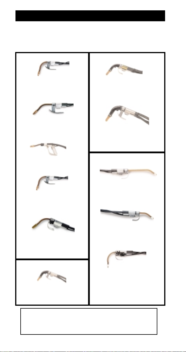
CHOOSE THE PROPER INNERSHIELD GUN
Lincoln Innershield Guns
Rated Amperage, Duty Cycle and Wire Sizes
For proper CTWD use the appropriate insulated guide. For
specific information on wire size and cable length, please see
your local Lincoln representative.
K126-1, -2 Gun with 62° Nozzle
350 Amps at
60% Duty Cycle
Wire Size: .062–3/32”(1.6-2.4mm)
K206 Gun
350 Amps at 60%
Duty Cycle
Wire Size: .062–3/32"(1.6-2.4mm)
K116 -2 Gun
600 Amps at
60% Duty Cycle
Wire Size .120–7/64”(3.0-2.8mm)
K361-10 Gun
350 Amps at
60% Duty Cycle
Wire Size .068–5/64”(1.7-2.0mm)
K289-1, -4
500 Amps at
60% Duty Cycle
Wire Size: .120–7/64"(3.0-5.6mm)
K309 Gun
250 Amps at
60% Duty Cycle
Wire Size:.062–3/32"(1.6-2.4mm)
K115-1, -2, -3, -4, -5 Guns with
82° Nozzle
450 Amps at
60% Duty Cycle
Wire Size: .068–.120”(1.7-3.0mm)
K115-8, -10 Guns with 45°
Nozzle
450 Amps at
60% Duty Cycle
Wire Size: .068–.120”(1.7-3.0mm)
K264-8 Gun with 30° Long Tube
for LN-23P
250 Amps at 60% Duty Cycle
Wire Size: .068–5/64”(1.7-2.0mm)
K345 -10 Gun with 90° Standard
Tube for LN-23P
350 Amps at 60% Duty Cycle
Wire Size: .068–5/64”(1.7-2.0mm)
K355-10 Gun with 90° Tube for
LN-23P
250 Amps at
60% Duty Cycle
Wire Size: .068–5/64”(1.7-2.0mm)
Fume Extraction Guns
LN-23P Guns
Innershield Guns
Fume Extraction Gun
INNERSHIELD GUNS
Page 17

– 17 –
Current Amps Total Work and Electrode Cable Length
(1)
60% Duty Cycle
0-50 ft. (0-15m) 50-100 ft. (15-30m)
300 1 (50mm2) 1 (50mm2)
400 2/0 (70mm2) 2/0 (70mm2)
500 2/0 (70mm2) 2/0 (70mm2)
600 3/0 (95mm2) 3/0 (95mm2)
(1)
mm2 equivalent according to IEC (International Electrical Code).
PREPARE THE WORK
Clean the joint by removing excessive scale, rust, moisture, paint,
oil and grease from the surface. As with all welding applications,
joint cleanliness is necessary to avoid porosity and to attain the
travel speeds indicated in the procedures.
Tack weld with Innershield wire or Fleetweld® 35LS, Jetweld®
LH-70 or Jetweld 2 manual stick electrodes. If other electrodes are
used, Innershield slag removal may be difficult in the area of the
tacks.
The work connection can be placed either at the beginning or at
the end of the weld, depending upon the application. If necessary,
try different locations until the best weld quality is obtained.
Clamp the work cable to the work so there is a positive and clean
metal-to-metal contact point. Poor work connections raise system
voltage losses and can result in convex or ropey beads typical of
low voltage, even if the machine meters indicate proper voltage.
Never use undersize or badly worn work cables. Choose the
cable size per the following table:
WELDING PREPARATIONS
OPTIMIZING FEEDING
Most feeding problems are caused by improper handling of the
gun cable or wire.
1. Do not kink or pull the cable around sharp corners. Keep the
gun cable as straight as possible when welding.
2. Do not allow two-wheelers, fork lift trucks, etc. to run over the
cables.
3. Keep the cable clean per instructions in the wire feeder
operating manual.
4. Innershield wire has proper surface lubrication on it. Use only
clean, rust-free wire.
5. Replace the nozzle contact tip when it becomes worn or the
end appears fused or deformed.
Page 18

SET THE CONTACT TIP TO WORK DISTANCE (CTWD)
CTWD is measured from the end of the contact tip to the work.
Maintain this length within ±1/8” (3.2mm.) for CTWD ≤1” (25 mm)
or within ±1/4” (6.4 mm) for CTWD >1” (25 mm) during welding.
To obtain the proper CTWD when using an insulated guide:
1. Remove the insulated guide from the end of the gun tube.
2. Inch the wire out beyond the end of the contact tip until you
obtain the CTWD specified for each size and type electrode.
3. Replace insulated guide.
4. The length of wire protruding from the end of the guide is
visible stickout. Maintaining this visible CTWD with the guide
in place gives the correct CTWD while welding. For wires using
the T12313 Thread Protector, the contact tip is exposed.
This
tip should NEVER be allowed to touch the work when the
power source output contactor is closed, as it is
electrically “hot”.
– 18 –
WARNING: When inching, the wire is always electrically “hot”
to ground, except on wire feeders with a “cold inch” feature.
Arc
Work
Wire
Electrode
Visible
CTWD
Insulated Guide
Contact Tip
Gun Tube (Nozzle)
Contact Tip to Work Distance
(CTWD)
WELDING TECHNIQUES
Page 19

– 19 –
SET THE WIRE FEED SPEED
Adjust the wire feed speed using the WFS control on the wire
feeder. Set to the suggested procedures. See pages 30-39. The
approximate amperage corresponding to each WFS at the
specified CTWD is also listed in the table. Amperage depends on
wire feed speed and CTWD. If the CTWD is shortened, amperage
will increase. If a wire feed speed meter is not available it may be
measured by running the wire out for 6 seconds, then measure the
length of wire fed and multiply by 10 to get the WFS in inches per
minute (in/min).
START THE ARC
With the proper visible CTWD set, position the gun with the wire
lightly touching the work. Avoid pushing the wire into the joint
before starting the arc. Press the gun trigger to start the weld.
Release the trigger and pull the gun from the work to stop the arc.
Some welders accustomed to manual welding with stick electrode
tend to push the wire into the joint as it burns away. Since the wire
is mechanically fed, this must be avoided.
SET THE VOLTAGE
Adjust the voltage to the suggested procedures as measured by
the wire feeder voltmeter or voltmeter placed between the wire
feeder contact block and workpiece. See pages 30-39. The
presence of surface porosity indicates that the arc voltage is too
high and should be lowered. An excessively convex or ropey bead
indicates that the voltage is too low. Increase the voltage setting to
reduce the convexity or ropey appearance of the bead. Also,
check for poor work cable connections, undersized or damaged
work cables, and poor cable clamps.
TRAVEL SPEED
As in all welding processes, use a travel speed which keeps the
arc at the front edge of the weld puddle and produces the desired
weld size. Maintain a uniform travel speed. The best way to do this
is to maintain a uniform distance between the wire and the molten
slag behind the wire. Travel speed is usually faster with Innershield
wire than with stick electrodes because of the higher deposit rate.
Many welders tend to move too slowly when they first weld with
Innershield wire.
WELDING TECHNIQUES
Page 20

– 20 –
WELDING TECHNIQUES
LOADING 13-14 LB. (5.9-6.5 kg) COILS ON A 2”
(50mm) SPINDLE
1. Remove the locking collar and the cover plate from K435
spindle adapter.
3. Unpack the 14 lb. (6.4kg) coil of wire. Be sure not to bend the
side tabs of the coil liner. Straighten any tabs that may have
been bent.
4. Remove the start end of the coil, cut off the bent end,
straighten the first six inches. Be sure the cut end of the wire is
round and burr free before the new coil into the drive rolls.
Thread it through the feeding wire feed liner until about four
inches of wire is exposed.
5. Replace the front reel cover and center clamping collar. To
prevent the wire from dereeling, keep the reel from turning
and tighten the clamping collar securely.
6. See wire feeder operating manual for instructions on loading
the wire into the drive roll and guide tubes.
Page 21

– 21 –
HANDLING POOR FITUP
Innershield bridges gaps better than most welding processes.
When using NS-3M at 3” (76mm) CTWD, temporarily increasing
the visible CTWD to as much as 3-1/4” (83mm) helps reduce
penetration and burnthrough to bridge gaps. Poor fitup may
require a small, temporary increase in visible CTWD or a reduction
in WFS setting.
USE A DRAG TECHNIQUE
Tilt the gun back away from the weld puddle in the direction of
travel about the same as required in stick electrode welding. If slag
tends to run ahead of the arc, increase the drag angle. However, if
the drag angle becomes too great, erratic arc action and excessive
arc blow will result in porosity and poor bead shape.
USE THE PROPER WIRE ANGLE TO JOINT
Horizontal Fillets
For 1/4” (6mm) and smaller fillets, point the wire at the joint. The
wire angle to the joint should be about 40°.
For best bead shape on 5/16” (8mm) and large horizontal fillets,
point the wire at the bottom plate close to the corner of the joint.
The angle between the wire and the bottom plate should be less
than 45°. Using this position, the molten metal washes onto the
vertical plate.
40˚
WELDING TECHNIQUES
DRAG
ANGLE
TRAVEL
40ß
Page 22

– 22 –
MAKING VERTICAL UP WELDS
Use 5/64” (2.0mm) size and less.
NR-202 NR-203M
NR-203MP NR-203 Nickel (1%)
NR-211-MP NR-212
NR-232 NR-233
Smaller sizes, 5/64" and less are recommended for all position
welding.
When welding out-of-position, don’t whip, break the arc, move out
of the puddle or move too fast in any direction. Use WFS in the low
portion of the range. General techniques are illustrated below.
Experience will show how much hesitation and upward step is
required for high quality welds.
Generally, keep the wire nearly perpendicular to the joint as
illustrated. The maximum angle above perpendicular may be
required if porosity becomes a problem.
Groove Welds
1. Make a distinct hesitation at the outer edges of bevel.
2. Minimize each upward step. Do not step up at the edges.
Come straight out from the hesitation point and move up
across the weld.
WELDING TECHNIQUES
Max. 20°
Page 23

– 23 –
Vertical Up Fillet and Lap Welds
1. Make larger welds with the following techniques:
a. On 1/4” (6mm) welds, a short side-to-side motion is
usually sufficient.
b. On larger welds, use a triangular weave (see number
1 in the sketch below) with a distinct hesitation at the
outer edges for the first pass.
c. Use a side-to-side weave (see number 2 in the sketch
below) similar to that used for butt welds on the
second and later passes. The first pass should have a
face width of 5/16” - 3/8” (8 - 10mm) before
starting this weave.
MAKING DOWNHILL AND VERTICAL DOWN WELDS
With NR-202, NR-203 (types), NR-207, NR-208-H,
NR-211-MP, NR-212
Make 1/4” (6mm) or smaller welds using vertical down techniques.
The excellent high speed welding characteristics are best utilized
for low cost single pass welds by positioning the work downhill or
vertical down. About a 60° downhill angle with 5/64” or 3/32” (2.0
or 2.4mm) electrode usually provides maximum speed.
Use stringer beads and currents in the middle to high portion of
the range. Tip the electrode up so that arc force helps hold the
molten metal in the joint. Move as fast as possible consistent with
desired bead shape.
WELDING TECHNIQUES
1
2
10-15°
Page 24

– 24 –
WORKING WITH NS-3M
To calculate electrical stickout, subtract 1/4” from CTWD.
.120" (3.0mm) NS-3M
When using the long CTWD of 3” to 4” (75 to 100mm), the long
length of wire beyond the contact tip has greater electrical
resistance. Because of the greater resistance, the wire is heated to
a higher temperature so it melts more rapidly in the arc to increase
deposition rates and lower weld cost.
Using a long CTWD reduces penetration and makes starts more
difficult. The long distance from the contact tip to the work also
allows the wire to wander more than if a shorter CTWD is used.
Linc-Fill welding with 4” (100mm) CTWD is generally limited to
9/16” (8mm) (leg) and larger flat fillets, multiple pass flat fillets and
the fill passes of flat deep groove butt joints.
When changing the insulated guide tips to increase CTWD from
3” to 4” (75 to 100mm), the meter voltage reading must be
increased by 2 or 3 volts to maintain a good flat bead. The current
(or WFS) control setting must also be adjusted to increase the wire
feed speed to obtain the same welding current.
For welding with 4” (100mm) CTWD, follow the basic instructions
under “Start The Arc”, on page 19. Start with 3/4” (19mm) visible
CTWD. When the arc is established, increase the CTWD to the
normal 1-5/8” (41mm) visible CTWD using the proper insulated
guide. See the tables on pages 30-39 for the proper CTWD for
each size wire.
WELDING TECHNIQUES
Page 25

– 25 –
Well made Innershield welds have excellent appearance.
TROUBLESHOOTING
To Eliminate Porosity (In order of importance)
1. Clean the joint from moisture, rust, oil, paint and
other contaminants
2. Decrease voltage
3. Increase CTWD
4. Increase WFS
5. Decrease drag angle
6. Decrease travel speed
To Eliminate a Ropey Convex Bead (In order of importance)
1. Increase voltage (within wire specifications)
2. Decrease CTWD
3. Decrease WFS
4. Decrease travel speed
5. Decrease drag angle
To Reduce Spatter (In order of importance)
1. Adjust voltage
2. Decrease drag angle
3. Decrease CTWD
4. Increase WFS
5. Decrease travel speed
To Correct Poor Penetration (In order of importance)
1. Decrease CTWD 4. Decrease travel speed
2. Increase WFS 5. Decrease drag angle
3. Decrease voltage
OPERATING GUIDE
Page 26

– 26 –
To Minimize Arc Blow (In order of importance)
Arc blow occurs when thr arc stream does not folow the shortest
path between the electrode and the workpiece.
1. Move work connection locations
2. Decrease drag angle
3. Increase CTWD
4. Decrease WFS and voltage
5. Decrease travel speed
To Eliminate Stubbing (In order of importance)
Stubbing occurs when the wire drives through the molten
puddle and hits the bottom plate tending to push the gun up.
1. Increase voltage
2. Decrease WFS
3. Decrease CTWD
4. Decrease drag angle
Equipment Troubleshooting Instructions are included in the
operating manuals for the wire feeder and power source. Be sure
to confirm the equipment is operating properly.
EFFECT OF OPERATING VARIABLES
The four major operating variables, arc voltage, wire feed speed
(WFS), travel speed and CTWD, are interdependent. If one is
changed, usually the other three must also be adjusted.
Arc Voltage
If WFS, travel speed and CTWD are held constant, changing the
arc voltage will have the following effects:
1. Higher arc voltage results in a wider and flatter bead.
2. Excessive arc voltage causes porosity.
3. Low voltage causes a convex ropey bead.
4. Extremely low voltage will cause the wire to stub on the plate.
That is, the wire will dive through the molten metal and strike
the joint bottom, tending to push the gun up.
Wire Feed Speed (WFS) - (or welding current)
If arc voltage, travel speed and CTWD are held constant, WFS
variations have the following major effects:
1. Increasing the WFS increases melt-off and deposition rates.
2. Excessive WFS produces convex beads. This wastes weld
metal and results in poor appearance.
OPERATING GUIDE
Page 27

– 27 –
3. Increasing WFS also increases the maximum voltage which can
be used without porosity. Lowering the WFS requires lowering
the voltage to avoid porosity.
As the WFS is increased, the arc voltage must also be increased to
maintain proper bead shape.
Travel Speed
If arc voltage, WFS and CTWD are held constant, travel speed
variations have the following major effects:
1. Too high a travel speed increases the convexity of the bead
and causes uneven edges.
2. Too slow a travel speed results in slag interference, slag
inclusions and a rough, uneven bead.
Contact Tip to Work Distance (CTWD)
If the voltage and wire feed speed setting and the travel speed are
held constant, variations in CTWD have the following major effects:
1. Increasing CTWD reduces the welding current. Decreasing
CTWD increases current.
2. Increasing CTWD reduces actual arc voltage and results in
more convex beads and reduces the tendency of porosity.
3. Momentarily increasing CTWD can be used to reduce
burn-through tendency when poor fitup is encountered.
WELDER QUALIFICATION TEST
1. Remove mill scale and other contaminants from mating
surfaces of backing and test plates.
2. Preheat to 300°F for 3/8” (10 mm) thick welder qualification test.
3. Attach backing so that it is tight (NO GAP)
4. Use the least drag angle to keep the slag back from the arc.
5. Aging at 220°F, (104°C) for 48 hrs. is permitted by AWS
A5.20-95, paragraph A8.3. A naturally aged specimen may
take months to achieve the specified properties.
Because design, fabrication, erection and welding variables
affect the results obtained in applying this type of
information, the serviceability of a product or structure is
the responsibility of the builder/user.
OPERATING GUIDE
Page 28

– 28 –
In general, Innershield electrodes will produce weld deposits which
achieve diffusible hydrogen levels below 16 ml per 100 grams
deposited metal. These products, like other products which produce
deposits low in diffusible hydrogen, must be protected from exposure
to the atmosphere in order to;
(a) maintain hydrogen levels as low as possible
(b) prevent porosity during welding
(c) prevent rusting of the product.
Accordingly, the following storage conditions are recommended for
Innershield electrodes in their original, unopened packages:
The recommended storage conditions are such that they maintain
environmental conditions above the dew point to prevent moisture
condensation on product.
For best results, electrode should be consumed as soon as
practicable. Properly stored electrode may be kept three years or
more from the date of manufacture. Consult your Lincoln distributor
or sales representative if there is a question as to when the electrode
was made.
Once the electrode packaging is opened, Innershield electrodes can
be contaminated by atmospheric moisture. Care has been taken in
the design of these products to ensure that they are resistant to
moisture pick-up; however, condensation of moisture from the
atmosphere onto the surface of the electrode can be sufficient to
degrade the product.
The following minimum precautions should be taken to safeguard the
product after opening the original package. Electrode should be used
within approximately 1 week after opening the original package.
Opened electrodes should not be exposed to damp moisture
conditions or extremes in temperature and/or humidity where surface
condensation can occur. Electrodes mounted on wire feeders should
be protected against condensation. It is recommended that electrode
removed from its original packaging be placed in poly bags (4 mil
minimum thickness) when not in use.
Innershield electrodes will evidence high moisture levels in the form of
gas tracks, higher spatter and porosity. Any rusty electrode should be
discarded.
STORING INNERSHIELD ELECTRODES
Page 29

– 29 –
Innershield Products Used for Applications
Requiring More Restrictive Hydrogen Control (-H
Electrodes)
The AWS specifications for flux-cored electrodes, AWS A5.20 and
A5.29, state that “Flux-cored arc welding is generally considered to
be a low hydrogen welding process”. Further, these specifications
make available optional supplemental designators for maximum
diffusible hydrogen levels of 4, 8 and 16 ml per 100 grams of
deposited weld metal.
Some Innershield products have been designed and manufactured to
produce weld deposits meeting these more stringent diffusible
hydrogen requirements. These electrodes are usually distinguished
by an “H” added to the product name. These electrodes will remain
relatively dry under recommended storage conditions in their original,
unopened package or container.
For applications in which the weld metal hydrogen must be controlled
(usually H8 or lower), or where shipping and storage conditions are
not controlled or known, only hermetically sealed packaging is
recommended. Many Innershield electrodes are available in
hermetically sealed packages.
Once the package has been opened, the electrode should be used
as soon as practicable.
STORING INNERSHIELD ELECTRODES
Page 30

Plate Size – T (in) 14 GA 10 GA
Pass 1 1
Electrode
Polarity
CTWD 1” 1”
Wire Feed Speed 50 75
(in/min)
Arc Volts 16
(1)
18
(1)
Travel Speed (in/min) As Req’d As Req’d
Deposit Rate (lbs/hr) 2.9 4.5
– 30 –
HORIZONTAL, FLAT, DOWNHILL
VERTICAL DOWN AND OVERHEAD
HORIZONTAL, FLAT, DOWNHILL AND
VERTICAL DOWN
.068" NR-232 DC( – )
5/64” NR-211-MP MP DC( – )
Plate Size – T (in) 16 GA 12 GA
Pass 1 1
Electrode
Polarity
CTWD 1” 1”
Wire Feed Speed 40 60
(in/min)
Arc Volts 15 16
Travel Speed (in/min) As Req’d As Req’d
Deposit Rate (lbs/hr) 1.7 2.6
.068" NR-232 DC( – )
.068" NR-211-MP MP DC( – )
(1) Use 1 volt lower for Vertical Down and Overhead.
NR-211-MP WELDING PROCEDURES
Because design, fabrication, erection and welding variables
affect the results obtained in applying this type of information,
the serviceability of a product or structure is the responsibility
of the builder/user.
Page 31

Plate Size – T (in) 3/4 and up
Pass 1 2 & up
Electrode
Polarity
CTWD 1– 1-1/2 " 3/4 – 1"
Drag Angle 5 – 30° 0 – 30°
Wire Feed Speed 110 – 135 150 – 170
(in/min)
Arc Volts 18 – 19 19 – 21 19 – 21 20 – 22
Travel Speed (in/min) As Req’d As Req’d
Deposit Rate (lbs/hr) 3.8 – 4.7 5.2 – 6.0
VERTICAL UP AND OVERHEAD BUTT WELDS
– OPEN ROOT
.068" NR-232 DC( – )
– 31 –
Plate Size – T (in) 5/16 3/8, 3/8 & Up
Leg Size – L (in) 1/4 5/16 over 5/16
Pass 1 1 As req’d
Electrode
Polarity
CTWD 3/4 - 1-1/4”
Drag Angle 20 – 30°
Wire Feed Speed 165 – 320 165 – 250
(in/min)
Arc Volts 20 – 22 25 – 27 20 – 22 23 – 24
Travel Speed (in/min) 15 17 As Req’d
Deposit Rate (lbs/hr) 5.9 11.3 5.9 – 8.6
FLAT AND HORIZONTAL FILLET WELDS
.068" NR-232 DC( – )
Because design, fabrication, erection and welding variables
affect the results obtained in applying this type of information,
the serviceability of a product or structure is the responsibility
of the builder/user.
NR-232 .068” WELDING PROCEDURES
Page 32

– 32 –
Plate Size – T (in) 3/8 & up
Pass 1 2 & up
Electrode
Polarity
CTWD 3/4 – 1-1/4"
Drag Angle 5 – 20°
Wire Feed Speed 155 165
(in/min)
Arc Volts 21 22
Travel Speed (in/min) 4.3 – 5.6 As Req’d.
Deposit Rate (lbs/hr) 5.5 – 5.9
VERTICAL UP AND OVERHEAD BUTT –
STEEL BACKUP
.068" NR-232 DC( – )
Plate Size – T (in) 5/16 3/8 3/8 & Up
Leg Size – L (in) 1/4 5/16 over 5/16
Pass 1 1 As req’d
Electrode
Polarity
CTWD 3/4 – 1"
Drag Angle 0 – 30°
Wire Feed Speed 130 – 165
(in/min)
Arc Volts 19 – 21 21 – 23
Travel Speed (in/min) 6.5 – 9.5 5 – 7 As Req’d
Deposit Rate (lbs/hr) 4.5 – 5.9
ALL POSITION FILLET WELDS
.068" NR-232 DC( – )
NR-232 .068” WELDING PROCEDURES
Because design, fabrication, erection and welding variables
affect the results obtained in applying this type of information,
the serviceability of a product or structure is the responsibility
of the builder/user.
Page 33

– 33 –
Plate Size – T (in) 3/4 & up
Pass 1 2 & up
Cap Passes
(Horizontal)
Electrode
Polarity
CTWD 1 – 1-1/2" 3/4 – 1-1/4"
Drag Angle 5 – 30° 0 – 30°
Wire Feed Speed 110 – 135 250 – 275 180 – 195
(in/min)
Arc Volts 18–20/19–21 20–22/23–25 20–21/23–24
Travel Speed (in/min) 4.3 – 5.6 As Req’d As Req’d
Deposit Rate (lbs/hr) 3.8 – 4.6 8.6 – 9.5 6.2 – 6.8
FLAT AND HORIZONTAL BUTT WELDS
.068" NR-232 DC( – )
NR-232 .068” WELDING PROCEDURES
Because design, fabrication, erection and welding variables
affect the results obtained in applying this type of information,
the serviceability of a product or structure is the responsibility
of the builder/user.
Page 34

– 34 –
Because design, fabrication, erection and welding variables
affect the results obtained in applying this type of information,
the serviceability of a product or structure is the responsibility
of the builder/user.
Plate Size – T (in) 5/16 3/8, 1/2 & up
Leg Size – L (in) 1/45/16 3/8 & up
Pass 1 1 As req’d
Electrode
Polarity
CTWD 3/4 – 1" 3/4 – 1" 3/4 – 1"
Drag Angle 0° 0 – 30° 0 – 30°
Wire Feed Speed 155 – 170 155 – 170 155 – 170
(in/min)
Arc Volts 20 – 23 20 – 23 20 – 23
Travel Speed (in/min) 9.5 6.5 As Req’d
Deposit Rate (lbs/hr) 6.0 – 6.5 6.0 – 6.5 6.0 – 6.5
ALL POSITION FILLET WELDS
.072" NR-232 DC( – )
Plate Size – T (in) 3/4 & up
Pass 1 2 & up cap
Electrode
Polarity
CTWD 1 – 1-1/2" 3/4 – 1" 3/4 – 1"
Drag Angle 5 – 30° 0 – 30°
(1)
0 – 30°
Wire Feed Speed 85 – 110 155 155
(in/min)
Arc Volts 17 – 18 22 20
Travel Speed (in/min) As Req’d As Req’d As Req’d
Deposit Rate (lbs/hr) 3.3 – 4.3 6.0 6.0
.072" NR-232 DC( – )
VERTICAL UP AND OVERHEAD BUTT WELDS –
OPEN ROOT
(1)
At a travel speed of 10 in./min, a slight push angle is preferred.
NR-232 .072” WELDING PROCEDURES
Page 35

– 35 –
Because design, fabrication, erection and welding variables
affect the results obtained in applying this type of information,
the serviceability of a product or structure is the responsibility
of the builder/user.
VERTICAL UP AND OVERHEAD BUTT WELDS –
STEEL BACKUP
Plate Size – T (in) 3/8 & up
Pass 1 2 & up cap
Electrode
Polarity
CTWD 3/4" 3/4” 3/4”
Drag Angle 0° 5 – 20° 5 – 20°
Wire Feed Speed 155 155 155
(in/min)
Arc Volts 22 22 20
Travel Speed (in/min) As Req’d As Req’d As Req’d
Deposit Rate (lbs/hr) 6.0 6.0 6.0
.072" NR-232 DC( – )
FLAT AND HORIZONTAL FILLET WELDS
(1)
For maximum penetration, point the electrode into the corner or slightly
into the butting corner.
Plate Size – T (in) 5/16 3/8 3/8, & up
Leg Size – L (in) 1/45/16 over 5/16
Pass 1 1 As req’d
Electrode
Polarity
CTWD 3/4 – 1-1/4” 3/4 – 1-1/4” 3/4 – 1-1/4”
Drag Angle 20 – 30° 20 – 30° 20 – 30°
Wire Feed Speed 290 290 250
(in/min)
Arc Volts 23 – 24 23 – 24 21 – 22
Travel Speed (in/min) 16 11.5 As Req’d
Deposit Rate (lbs/hr) 11 11 9.5
.072" NR-232 DC( – )
NR-232 .072” WELDING PROCEDURES
Page 36

– 36 –
Plate Size – T (in) 3/4 & up
Pass 1 2-cap
Cap Passes
(Horizontal)
Electrode
Polarity
CTWD 1-1/4 – 1-1/2” 3/4 – 1-1/4” 3/4 – 1-1/4”
Drag Angle 5 – 30° 0 – 30° 0 – 30°
Wire Feed Speed 85 – 110 220 – 250 155 – 170
(in/min)
Arc Volts 17 – 18 20 – 22 20 – 21
Travel Speed (in/min) As Req’d As Req’d As Req’d
Deposit Rate (lbs/hr) 3.3 – 4.5 8.5 – 9.5 6.0 – 6.5
Because design, fabrication, erection and welding variables
affect the results obtained in applying this type of information,
the serviceability of a product or structure is the responsibility
of the builder/user.
FLAT AND HORIZONTAL BUTT WELDS
.072" NR-232 DC( – )
NR-232 .072” WELDING PROCEDURES
Page 37

– 37 –
Plate Size – T (in) 5/16 3/8 1/2 Over 1/2
Leg Size – L (in) 1/4 5/16 3/8 Over 3/8
Pass 1 1 1 As req’d
Electrode
Polarity
CTWD 3/4"
(2)
3/4"
(2)
7/8"
(2)
7/8"
(2)
Drag Angle 0° 0 – 20° 0 – 20° 0 – 20°
Wire Feed Speed 120 130 130 130
(in/min)
Arc Volts 19 – 20 20 – 21 20 – 21 20 – 21
Travel Speed (in/min) 8 6 4.5 As Req’d
Deposit Rate (lbs/hr) 5.7 6.2 6.2 6.2
Because design, fabrication, erection and welding variables
affect the results obtained in applying this type of information,
the serviceability of a product or structure is the responsibility
of the builder/user.
ALL POSITION FILLET WELDS
5/64" NR-232 DC( – )
(2)
For best slag control, start at 1", then reduce.
FLAT AND HORIZONTAL FILLET WELDS
Plate Size – T (in) 5/16 3/8 Over 3/8
Leg Size – L (in) 1/4 5/16 over 5/16
Pass 1 1 As req’d
Electrode
Polarity
CTWD 1” 1” 1”
Drag Angle 20 – 30° 20 – 30° 20 – 30°
Wire Feed Speed 175 175 175
(in/min)
Arc Volts 21.5 – 22.5 21.5 – 22.5 20.5 – 21.5
Travel Speed (in/min) 14 10.5 As Req’d
Deposit Rate (lbs/hr) 8.4 8.4 8.4
5/64" NR-232 DC( – )
NR-232 5/64” WELDING PROCEDURES
Page 38

– 38 –
FLAT AND HORIZONTAL BUTT WELDS
VERTICAL UP BUTT WELDS –
OPEN ROOT
Plate Size – T (in) 3/8 & up
Pass 1
(1)
2 & up
Electrode
Polarity
CTWD 1-1/4 – 1-1/2” 1”
Drag Angle 5 – 30° 5 – 30°
Wire Feed Speed 65 – 70 180
(in/min)
Arc Volts 17 – 17.5 22 – 23
Travel Speed (in/min) As Req’d 5 – 9
Deposit Rate (lbs/hr) 2.9 – 3.2 8.7
5/64" NR-232 DC( – )
(1)
With a steel backup, start with the second pass procedure and a
minimum root opening of 5/16".
Plate Size – T (in) 3/8 & up
Pass 1 2 3 & up
Electrode
Polarity
CTWD 1-1/4 – 1-1/2 1"
(2)
1"
(2)
Drag Angle 5 – 40° 0 – 30° 0 – 30°
Wire Feed Speed 60 – 65 115 130
(in/min)
Arc Volts 16 – 17 19 – 20 20 – 21
Travel Speed (in/min) As Req’d 3 – 5 3 – 5
Deposit Rate (lbs/hr) 2.7 – 2.9 5.5 6.2
5/64" NR-232 DC( – )
(2)
For best slag control, start at 1-1/4", then reduce.
Because design, fabrication, erection and welding variables
affect the results obtained in applying this type of information,
the serviceability of a product or structure is the responsibility
of the builder/user.
NR-232 5/64” WELDING PROCEDURES
Page 39

– 39 –
Because design, fabrication, erection and welding variables
affect the results obtained in applying this type of information,
the serviceability of a product or structure is the responsibility
of the builder/user.
VERTICAL UP AND OVERHEAD BUTT WELDS –
STEEL BACKUP
Plate Size – T (in) 3/8 & up
Pass 1 2 & up
Electrode
Polarity
CTWD 1"
(1)
1"
(1)
Drag Angle 0 – 30° 0 – 30°
Wire Feed Speed 115 130
(in/min)
Arc Volts 19 – 20 20 – 21
Travel Speed (in/min) 3 – 5 3 – 5
Deposit Rate (lbs/hr) 5.5 6.2
5/64" NR-232 DC( – )
(1)
For best slag control, start at 1-1/4", then reduce.
NR-232 5/64” WELDING PROCEDURES
Page 40

– 40 –
Wire
Polarity, AWS Class. Wire Feed Arc Approx. Deposit
CTWD In (mm) Speed Voltage Current Rate
Wire Weight in/min (m/min) (volts) (amps) lbs/hr (kg/hr)
.120" NR-1 or NR-5 140 (3.6) 20 450 18.4 (8.3)
(DC+) E70T-3 160 (4.1) 21 500 22.0 (10.0)
1-3/8" (35) 240 (6.1) 23 700 33.0 (15.0)
2.63 lbs/1000” 320 (8.1) 25 850 43.0 (19.5)
5/32” NR-1 100 (2.5) 21 600 21.2 (9.6)
(DC+) E70T-3 130 (3.3) 23 810 30.0 (13.6)
1-1/2" (38) 150 (3.8) 24 900 35.0 (15.9)
4.07 lbs/1000” 220 (5.6) 26 1120 48.3 (21.9)
3/32” NR-5 100 (2.5) 22 340 7.8 (3.5)
(DC+) E70T-3 150 (3.8) 23 435 12.3 (5.6)
1-1/4" (32) 200 (5.1) 24 510 16.9 (7.6)
1.60 lbs/1000” 250 (6.4) 26 575 21.4 (9.7)
3/32” NR-131 150 (3.8) 25 390 11.6 (5.3)
(DC+) E70T-10 200 (5.1) 26 490 15.6 (7.1)
1-1/2" (38) 250 (6.4) 26 570 19.6 (8.9)
1.58 lbs/1000” 425 (10.8) 27 810 33.6 (15.2)
.045” NR-152 60 (1.5) 15 95 1.1 (0.5)
(DC-) E71T-14 90 (2.3) 16 135 1.8 (0.8)
5/8" (16) 120 (3.0) 17 160 2.5 (1.1)
.39 lbs/1000” 150 (4.6) 18 180 3.2 (1.4)
.062” NR-152 30 (0.8) 13 90 1.2 (0.5)
(DC-) E71T-14 50 (1.3) 15 140 2.0 (0.9)
5/8" (16) 70 (1.8) 16 185 2.8 (1.3)
.74 lbs/1000” 110 (2.8) 19 265 4.4 (2.0)
.068” NR-152 40 (1.0) 13 95 1.9 (0.9)
(DC-) E71T-14 50 (1.3) 14 120 2.4 (1.1)
3/4" (19) 80 (2.0) 16 190 3.9 (1.8)
.91 lbs/1000” 110 (2.8) 20 240 5.4 (2.4)
5/64" NR-152 40 (1.0) 16 125 2.5 (1.1)
(DC-) E71T-14 80 (2.0) 19 260 4.9 (2.2)
1" (25) 100 (2.5) 21 310 6.1 (2.7)
1.15 lbs/1000" 125 (3.2) 24 355 7.6 (3.4)
(1) Single pass welding only.
(1)
(1)
(1)
(1)
(1)
(1)
(1)
(1)
OPERATING PARAMETERS
Page 41

– 41 –
Wire
Polarity, AWS Class. Wire Feed Arc Approx. Deposit
CTWD In (mm) Speed Voltage Current Rate
Wire Weight in/min (m/min) (volts) (amps) lbs/hr (kg/hr)
5/64” NR-202 50 (1.3) 19 150 2.0 (0.9)
(DC-) E71T-7 100 (2.5) 20 235 5.1 (2.3)
1-1/4” (32) 150 (3.8 )21 305 8.3 (3.8)
1.09 lbs/1000” 200 (5.1) 22 365 11.4 (5.2)
230 (5.8) 23 400 13.3 (6.0)
.068” NR-203MP 70 (1.8) 16 145 2.3 (1.0)
(DC-) E71T-8J 90 (2.3) 18 180 3.2 (1.5)
1" (25) 120 (3.0 20 225 4.3 (2.0)
.78 lbs/1000” 150 (3.8) 23 265 5.1 (2.3)
5/64” NR-203MP 50 (1.3) 16 130 1.9 (0.9)
(DC-) E71T-8J 90 (2.3) 19 220 4.2 (1.9)
1" (25) 120 (2.8) 20 280 5.3 (2.4)
1.03 lbs/1000” 140 (3.6) 22 310 6.8 (3.1)
5/64” NR-203 Ni (1%) 16 50 (1.3) 145 2.3 (1.0)
(DC-) E71T8-Ni1 18 70 (1.8) 195 3.3 (1.5)
1" (25) 20 110 (2.8) 275 5.3 (2.4)
1.52 lbs/1000” 21 120 (3.1) 290 5.8 (2.5)
22 140 (3.6) 310 6.9 (3.1)
3/32” NR-203 Ni (1%) 50 (1.3) 18 215 3.6 (1.6)
(DC-) E71T8-Ni1 70 (1.8) 19 260 5.1 (2.3)
1" (25) 95 (2.4) 21 315 7.0 (3.2)
1.52 lbs/1000” 110 (2.8) 22 345 8.1 (3.7)
130 (3.3) 23 385 9.6 (4.4)
.068” NR-207 80 (2.0) 17 190 3.0 (1.4)
(DC-) E71T8-K6 105 (2.7) 18 220 3.9 (1.8)
1" (25) 120 (3.0) 19 245 4.5 (2.0)
.78 lbs/1000” 170 (4.3) 21 300 6.5 (2.9)
(2) This electrode has been specifically designed for the demanding needs of pipe
welding.
(2)
OPERATING PARAMETERS
Page 42

– 42 –
Wire
Polarity, AWS Class. Wire Feed Arc Approx. Deposit
CTWD In (mm) Speed Voltage Current Rate
Wire Weight in/min (m/min) (volts) (amps) lbs/hr (kg/hr)
5/64" NR-207 & NR-207-H 70 (1.8) 17 205 3.4 (1.5)
(DC-) E71T8-K6 90 (2.3) 19 245 4.5 (2.0)
1-1/8" (29) 110 (2.8) 20 275 5.5 (2.5)
1.04 lbs/1000" 130 (3.3) 20 300 6.5 (2.9)
.035" NR-211-MP 14 50 (1.3) 30 .65 (0.3)
(DC-) E71T-11 15 70 (1.8) 60 1.00 (0.5)
5/8" (16) 16 90 (2.3) 90 1.35 (0.6)
.250 lbs/1000" 16.5 110 (2.8) 120 1.70 (0.8)
.045" NR-211-MP
70 (1.8) 15 120 1.1 (0.5)
(DC-) E71T-11 90 (2.3) 16 140 1.7 (0.8)
5/8" (16) 110 (2.8) 17 160 2.3 (1.0)
.39 lbs/1000" 130 (3.3) 18 170 2.7 (1.2)
.068" NR-211-MP
40 (1.0) 15 125 1.7 (0.8)
(DC-) E71T-11 75 (1.9) 18 190 3.4 (1.5)
1" (25) 130 (3.3) 20 270 6.1 (2.8)
.89 lbs/1000" 175 (4.4) 23 300 8.4 (3.8)
5/64" NR-211-MP
50 (1.3) 16 180 2.9 (1.3)
(DC-) E71T-11 75 (1.9) 18 235 4.5 (2.0)
1" (25) 120 (3.0) 20 290 7.4 (3.4)
1.17 lbs/1000" 160 (4.1) 22 325 10.0 (4.5)
3/32” NR-211-MP 50 (1.3) 16 245 4.2 (1.9)
(DC-) E71T-11 75 (1.9) 19 305 6.4 (2.9)
1-1/4” (32) 120 (3.0) 20 365 8.7 (3.9)
1.66 lbs/1000” 160 (4.1) 22 400 11.3 (5.1)
.045" NR-212 55 (1.4) 14 75 1.1 (0.5)
(DC-) E71TG-G 70 (1.8) 15 90 1.4 (0.6)
5/8" (16) 110 (2.8) 17 135 2.2 (1.0)
.39 lbs/1000" 150 (3.8) 19 170 3.0 (1.4)
.068" NR-212
60 (1.5) 16 145 2.4 (1.1)
(DC-) E71TG-G 75 (1.9) 18 180 3.2 (1.4)
1" (25) 120 (3.0) 20 230 5.2 (2.3)
.82 lbs/1000" 175 (4.4) 22 275 7.5 (3.4)
5/64" NR-212
60 (1.5) 16 200 3.3 (1.5)
(DC-) E71TG-G 75 (1.9) 18 225 4.1 (1.8)
1" (25) 110 (2.8) 20 275 6.2 (2.8)
1.06 lbs/1000" 150 (3.8) 22 325 8.4 (3.8)
(2) This electrode has been specially designed for the demanding needs of pipe welding.
Note: These are typical operating procedures and are not intended to serve as specific
procedures for any applications.
(2)
OPERATING PARAMETERS
Page 43

– 43 –
Wire
Polarity, AWS Class. Wire Feed Arc Approx. Deposit
CTWD In (mm) Speed Voltage Current Rate
Wire Weight in/min (m/min) (volts) (amps) lbs/hr (kg/hr)
.068” NR-232 110 (2.7) 19 195 3.9 (1.8)
(DC-) E71T-8 150 (3.8) 20 250 5.3 (2.4)
1" (25) 195 (5.0) 23.5 300 7.0 (3.2)
.75 lbs/1000” 320 (7.4) 26 400 11.4 (5.2)
.072” NR-232 80 (2.0) 17 130 3.3 (1.5)
(DC-) E71T-8 140 (3.6) 19.5 225 5.5 (2.5)
1" (25) 170 (4.3) 21.5 255 6.5 (2.9)
.78 lbs/1000” 290 (7.4) 24 350 11.0 (5.0)
5/64” NR-232 60 (1.5) 17 145 2.7 (1.2)
(DC-) E71T-8 115 (2.9) 18 260 5.5 (2.5)
1" (25) 130 (3.3) 20.5 285 6.2 (2.8)
1.00 lbs/1000 180 (4.6)” 22.5 365 8.7 (3.9)
5/64” NR-305 175 (4.5) 22 295 8.8 (4.0)
(DC+) E70T-6 260 (6.6) 24 385 13.1 (6.0)
1-3/8" (35) 280 (7.1) 25 405 14.2 (6.5)
1.05 lbs/1000 325 (8.3) 26 435 16.4 (7.5)
3/32” NR-305 160 (4.1) 22 330 11.0 (5.0)
(DC+) E70T-6 240 (6.1) 25 425 16.7 (7.6)
1-3/4" (44) 300 (7.6) 28 475 21.0 (9.5)
1.39 lbs/1000” 400 (10.2) 34 525 28.0 (12.7)
5/64” NR-311 100 (2.5) 21 190 5.0 (2.3)
(DC-) E70T-7 160 (4.1) 25 275 8.0 (3.6)
1-1/2" (38 240 (6.1) 26 355 12.4 (5.6)
1.07 lbs/1000” 300 (7.6) 28 410 15.8 (7.2)
3/32” NR-311 75 (1.9) 21 200 5.4 (2.5)
(DC-) E70T-7 135 (3.4) 24 300 10.2 (4.6)
1-3/4" (44) 150 (3.8) 25 325 11.4 (5.2)
1.62 lbs/1000” 270 (6.9) 30 450 22.0 (10.0)
OPERATING PARAMETERS
Page 44

– 44 –
Wire
Polarity, AWS Class. Wire Feed Arc Approx. Deposit
CTWD In (mm) Speed Voltage Current Rate
Wire Weight in/min (m/min) (volts) (amps) lbs/hr (kg/hr)
7/64” NR-311 100 (2.5) 23 325 10.0 (4.5)
(DC-) E70T-7 145 (3.7) 25 400 14.5 (6.6)
1-3/4" (44) 240 (6.1) 30 550 25.5 (11.6)
2.05 lbs/1000” 300 (7.6) 33 625 33.0 (15.0)
5/64” NR-311 Ni 100 (2.5) 22 170 3.9 (1.8)
(DC-) E70TG-K2 160 (4.0) 26 235 6.5 (2.9)
1-1/4" (32 200 (5.0) 27 270 8.3 (3.8)
.93 lbs/1000” 240 (6.1) 28 295 10.0 (4.5)
3/32” NR-311 Ni 75 (1.9) 21 200 4.2 (1.9)
(DC-) E70TG-K2 100 (2.5) 22 245 5.9 (2.7)
1-1/2" (38) 150 (3.8) 26 330 9.1 (4.1)
1.39 lbs/1000” 200 (5.0) 28 390 12.3 (5.6)
7/64” NR-311 Ni 100 (2.5) 23 310 8.4 (3.8)
(DC-) E70TG-K2 140 (3.5) 25 370 11.8 (5.4)
1-3/4" (44) 200 (5.0) 29 470 17.0 (7.7)
1.89 lbs/1000” 240 (6.1) 30 520 20.4 (9.2)
5/64” NS-3M 200 (5.1) 30 280 10.1 (4.6)
(DC+) E70T-4 240 (6.1) 31 315 12.1 (5.5)
2-1/4” (57) 260 (6.6) 31 330 13.2 (6.0)
1.03 lbs/1000” 300 (7.6) 32 350 15.2 (6.9)
3/32” NS-3M 110 (2.8) 29 250 8.2 (3.7)
(DC+) E70T-4 150 (3.8) 30 300 11.7 (5.3)
3" (76) 230 (5.8) 32 400 18.3 (8.3)
1.53 lbs/1000” 275 (7.0) (33 450 22.0 (10.0)
.120” NS-3M 140 (3.6) 29 380 15.5 (7.0)
(DC+) E70T-4 175 (4.4) 30 450 20.0 (9.1)
3" (76) 200 (5.1) 31 500 23.2 (10.5)
2.34 lbs/1000” 225 (5.7) 32 550 26.2 (11.9)
.120” NS-3M 210 (5.3) 36 450 25.0 (11.3)
(DC+) E70T-4 250 (6.4) 37 500 29.0 (13.2)
4" (102) 300 (7.6) 38 550 34.0 (15.4)
2.34 lbs/1000” 355 (9.0) 39 600 39.5 (18.0)
OPERATING PARAMETERS
Page 45

– 45 –
The suggested operating parameters listed in this publication are
not intended to serve as specific procedures for any application.
These suggested procedures represent the approximates the
procedure range of each individual electrode.
Arc voltage and/or wire feed speed may need to be adjusted
depending upon welding position, type of weld, base steel surface
condition or other factors. In general, use the highest voltage
possible consistent with porosity-free welds.
CTWD is measured from the work surface to the contact tip.
Maintain this length within ±1/8” (3.2mm.) for CTWD ≤1” (25 mm)
or within ±1/4” ( 6.4 mm) for CTWD >1” (25 mm) during welding.
Contact your Authorized Lincoln Distributor or your local Lincoln
Representative for specific procedures and techniques.
For more information on a particular Innershield wire, consult the
C3.200.
OPERATING PROCEDURES
Page 46

– 46 –
Full Size Drawings* of Parts for K126 and K206 Guns
Insulated
Guide for
K126
KP1995-1
for 2” (51 mm)
CTWD.
Length:
1 7/8”
(48 mm)
Nose Cone
Assembly
for K126,
K264, K345,
K355, K361
KP1987-1
Length:
1 3/8”
(35 mm)
Thread
Protector
KP2089-1
Insulated
Guide for
K126
KP2090-1
for 2 3/4”
(70 mm)
CTWD.
Length:
2 3/4”
(70 mm)
KP2099-3 for
2 3/4” (70 mm) CTWD.
Length: 2 1/2” (64 mm)
KP2099-4 for
2” (51 mm) CTWD.
Length: 2 1/8” (54 mm)
KP2099-2 for
1 1/2” (38 mm) CTWD.
Length: 1 5/8” (42 mm)
KP2099-1 for
3/4-1” (19-25 mm) CTWD.
Length: 1” (25 mm)
Insulated Guide
for K206
Contact Tip KP2100-xx
Electrode Contact Tip
Part No. Sizes (mm)
.062” (1.6) KP2100-2B1-1/16
.068”-.072”(1.7-1.8) KP2100-1B1-.072
5/64” (2.0) KP2100-4B1-5/64
3/32” (2.4) KP2100-3B1-3/32
Size stenciled on each tip.
Thread Protector for 3/4” to 1-1/2”
(19 to 38 mm) CTWD.
Note: When using the KP2089-1 Thread Protector on
a K126 or K309 gun with .062” through 3/32”
(1.6 through 2.4 mm) electrode, visible CTWD and
CTWD are identical.
* ll sizes of
insulated guides
NOT SHOWN
,
order specific
length needed
by part number.
INNERSHIELD GUN PARTS
Page 47

– 47 –
Electrode Contact Tip
Sizes (mm) Part No.
1/16” (1.6) KP2103-2B1-1/16
.
068-.072” (1.7) KP2103-1B1-.072
5/64” (2.0) KP2103-5B1-5/64
3/32” (2.4) KP2103-4B1-3/32
7/64 (2.8) KP2103-6B1-7/64
.120” (3.0) KP2103-3B1-120
Insulated
Guide for K115
& K116 3/32 &
120 NS-3M
KP1965-1 for
2 3/4” (70 mm)
CTWD. (Shown)
KP1954-2 for
3 3/4” (95 mm)
CTWD.
Length:
3 5/16”
(84 mm)
Contact Tip KP2103-xx
Insulated
Guide for K115
& K116
KP1971-1
for 1 1/2” (38 mm)
CTWD.
Extension Guide
for K289 - KP1994-1
5/64” (2.0 mm) for
3/4” (19 mm) CTWD.
Electrode Sizes Gun Tube 45˚ Gun Tube
For Gun
(1)
Inches (mm) (Nozzle) Part No. (Nozzle) Part No.
KP1920-1 --K126 & K309 KP1914-2 --K126 & K309 .062, .068, .072 KP1914-1 --K126 5/64, 3/32 KP1909-1 --K206 KP1921-1 --K115-
(1)
5/64 KP1919-2 KP1919-1
--- 3/32 KP1907-2 KP1910-2
--- 7/64, .120 KP1907-1 KP1910-1
K116-
(1)
3/32 KP1908-2 ---
--- 7/64, .120 KP1908-1 --K289-
(1)
3/32 KP1915-4 KP1915-2
--- 7/64, .120 KP1915-3 KP1915-1
Electrode Sizes Gun Tube
For Gun Inches (mm) (Nozzle)
(1)
Part No.
K345-10 .068, .072 90˚ nozzle - KP1920-1
& 5/64 62
˚ nozzle - KP1909-1
K355-10 30
˚ (Standard) - KP1914-2
30
˚ (Long) - KP1914-1
Full Size Drawings* of Parts for K115, K116 and K289 Guns
}
(1)
Several standard cable lengths, nozzles and wire sizes are available. See price book or your local
Lincoln distributor for more detailed information.
* All sizes of insulated guides
NOT SHOWN
, order specific
length needed by part number.
Size stenciled on each tip.
INNERSHIELD GUN PARTS
Page 48

– 48 –
LINCOLN
WELDING SCHOOL
Lincoln Welding School
22801 St. Clair Avenue
Cleveland, Ohio 44117-1199
Ask for bulletin ED122
You may reach us at: 216.383.2259
NEED WELDING TRAINING?
The Lincoln Electric Company operates the
oldest and most respected Arc Welding School in
the United States at its corporate headquarters in
Cleveland, Ohio. Over 100,000 men and women
have graduated from this premier school.
Tuition is affordable and class schedules are flexible
to meet your needs. For more information on the
Lincoln Welding School, please write to:
Classes are in Session from 8:00 AM to 2:30PM
Basic Plate & Sheet Metal
5 Weeks
Plasma, Oxy-fuel, Alloy & Hardfacing
3 Weeks
Pipe — select: • ASME or • API
3 Weeks
Price covers machine beveled pipe nipples used each week.
Prerequisite: Passing Basic Plate & Sheet Metal 5th Week Test
Gas Tungsten Arc Welding (GTAW - TIG)
1 Week
Price covers special alloy, aluminum, gas, etc. used each day.
Gas Shielded Arc Welding (GMAW - MIG) Semi-Automatic
1 Week
Flux Cored Arc Welding (FCAW) Semi-Automatic/Self
Shielded/Gas Shielded: 1 Week
• Submerged Arc Welding (SAW) Semi-Automatic/FullAutomatic: 1 Week
• Comprehensive Arc Welder Course
15 Weeks
Includes All Above Courses
Page 49

– 49 –
Low Hydrogen Pipe Module:
GMAW/FCAW/SMAW
1 Week
GTAW/SMAW
1 Week
Qualification Test Training:
AWS Test Semi-Automatic Flux Cored Arc Welding Self
Shielded (FCAW)
1 Week
3/8” AWS Fillet Test:
Shielded Metal Arc Welding (SMAW — Stick)
(1)
1 Week
AWS Test
Shielded Metal Arc Welding (SMAW - Stick)
(1)
1 Week
ASME Test
Shielded Metal Arc Welding (SMAW — Stick)
(1)
1 Week
ASME or API Pipe Welding Test Training
(1)
1 Week
Low Hydrogen Pipe Welding Test Training
(1)
1 Week
Certified Welding Inspector Course
(1)
1 Week
(1)
Actual Testing done in customer’s plant or Independent Testing Laboratory
Page 50

– 50 –
NOTES
Page 51

– 51 –
NOTES
Page 52

– 52 –
CUSTOMER ASSISTANCE POLICY
The business of The Lincoln Electric Company is manufacturing and selling high quality
welding equipment, consumables, and cutting equipment. Our challenge is to meet the needs
of our customers and to exceed their expectations. On occasion, purchasers may ask Lincoln
Electric for advice or information about their use of our products. We respond to our
customers based on the best information in our possession at that time. Lincoln Electric is not
in a position to warrant or guarantee such advice, and assumes no liability, with respect to
such information or advice. We expressly disclaim any warranty of any kind, including any
warranty of fitness for any customer’s particular purpose, with respect to such information or
advice. As a matter of practical consideration, we also cannot assume any responsibility for
updating or correcting any such information or advice once it has been given, nor does the
provision of information or advice create, expand or alter any warranty with respect to the sale
of our products.
Lincoln Electric is a responsive manufacturer, but the selection and use of specific products
sold by Lincoln Electric is solely within the control of, and remains the sole responsibility of
the customer. Many variables beyond the control of Lincoln Electric affect the results
obtained in applying these types of fabrication methods and service requirements.
Subject to Change — This information is accurate to the best of our knowledge at the time of
printing. Please refer to www.lincolnelectric.com for any updated information.
Cored Wire
C3.2400 2/04
TEST RESULTS
Test Results for Mechanical Properties, Deposit or Electrode Composition and Diffusable
Hydrogen levels were obtained at a single point in time under laboratory conditions from
random samples of representative material. Your results may vary within AWS
specification limits depending on a variety of conditions.
 Loading...