

Lincoln Electric MAXsa 10 Operator's Manual

Operator’s Manual
™
MAX
sa
10 CONTROLLER
For use with machines having Code Numbers:
12416
Register your machine:
www.lincolnelectric.com/register
Authorized Service and Distributor Locator:
www.lincolnelectric.com/locator
Save for future reference
Date Purchased
Code: (ex: 10859)
Serial: (ex: U1060512345)
IM10232 | Issue D ate Mar-15
© Lincoln Global, Inc. All Rights Reserved.
THANK YOU FOR SELECTING
A QUALITY PRODUCT BY
LINCOLN ELEC TRIC.
PLEASE EXAMINE CARTON AND EQUIPMENT FOR
DAMAGE IMMEDIATELY
When this equipment is shipped, title passes to the purchaser
upon receipt by the carrier. Consequently, claims for material
damaged in shipment must be made by the purchaser against the
transportation company at the time the shipment is received.
SAFETY DEPENDS ON YOU
Lincoln arc welding and cutting equipment is designed and built
with safety in mind. However, your overall safety can be increased
by proper installation ... and thoughtful operation on your part.
DO NOT INSTALL, OPERATE OR REPAIR THIS EQUIPMENT
WITHOUT READING THIS MANUAL AND THE SAFETY
PRECAUTIONS CONTAINED THROUGHOUT. And, most importantly,
think before you act and be careful.
WARNING
This statement appears where the information must be followed
exactly to avoid serious personal injury or loss of life.
CAUTION
This statement appears where the information must be followed
to avoid minor personal injury or damage to this equipment.
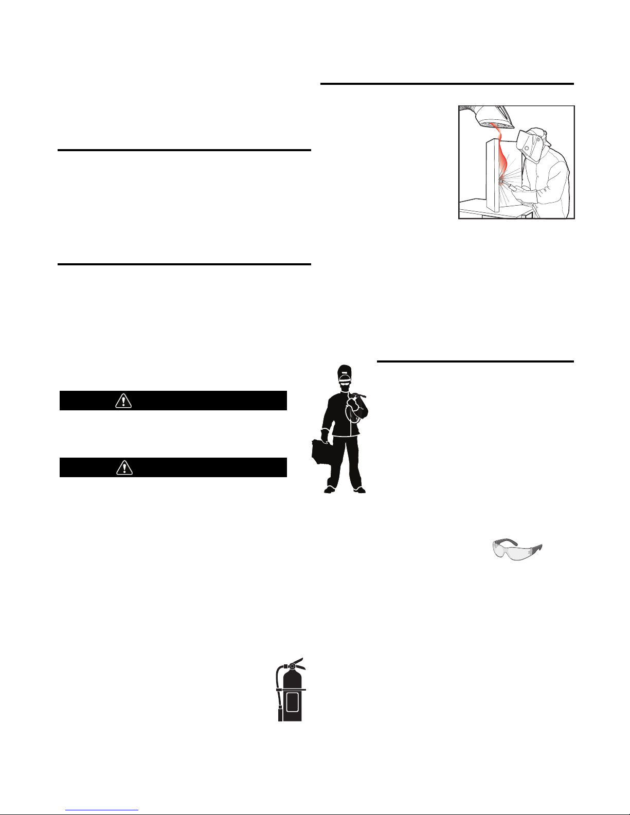
KEEP YOUR HEAD OUT OF THE FUMES.
DON’T get too close to the arc.
se corrective lenses if necessary
U
to stay a reasonable distance
away from the arc.
READ and obey the Safety Data
Sheet (SDS) and the warning label
that appears on all containers of
welding materials.
USE ENOUGH VENTILATION or
exhaust at the arc, or both, to
keep the fumes and gases from
your breathing zone and the general area.
IN A LARGE ROOM OR OUTDOORS, natural ventilation may be
adequate if you keep your head out of the fumes (See below).
USE NATURAL DRAFTS or fans to keep the fumes away
from your face.
If you de velop unusual symptoms, see your supervisor.
Perhaps the welding atmosphere and ventilation system
should be checked.
WEAR CORRECT EYE, EAR &
BODY PROTECTION
PROTECT your eyes and face with welding helmet
properly fitted and with proper grade of filter plate
(See ANSI Z49.1).
PROTECT your body from welding spatter and arc
flash with protective clothing including woolen
clothing, flame-proof apron and gloves, leather
leggings, and high boots.
PROTECT others from splatter, flash, and glare
with protective screens or barriers.
IN SOME AREAS, protection from noise may be appropriate.
BE SURE protective equipment is in good condition.
Also, wear safety glasses in work area
AT ALL TIMES.
SPECIAL SITUATIONS
DO NOT WELD OR CUT containers or materials which previously
had been in contact with hazardous substances unless they are
properly cleaned. This is extremely dangerous.
DO NOT WELD OR CUT painted or plated parts unless special
precautions with ventilation have been taken. They can release
highly toxic fumes or gases.
Additional precautionary measures
PROTECT compressed gas cylinders from excessive heat,
mechanical shocks, and arcs; fasten cylinders so they cannot fall.
BE SURE cylinders are never grounded or part of an
electrical circuit.
REMOVE all potential fire hazards from welding area.
ALWAYS HAVE FIRE FIGHTING EQUIPMENT READY FOR
IMMEDIATE USE AND KNOW HOW TO USE IT.
Safety 01 of 04 - 06/15/2016
SECTION A:
WARNINGS
CALIFORNIA PROPOSITION 65 WARNINGS
Diesel Engines
Diesel engine exhaust and some of its constituents are known
to the State of California to cause cancer, birth defects, and other
reproductive harm.
Gasoline Engines
The engine exhaust from this product contains chemicals known
to the State of California to cause cancer, birth defects, or other
reproductive harm.
ARC WELDING CAN BE HAZARDOUS. PROTECT
YOURSELF AND OTHERS FROM POSSIBLE SERIOUS
INJURY OR DEATH. KEEP CHILDREN AWAY.
PACEMAKER WEARERS SHOULD CONSULT WITH
THEIR DOCTOR BEFORE OPERATING.
Read and understand the following safety highlights. For
additional safety information, it is strongly recommended
that you purchase a copy of “Safety in Welding & Cutting ANSI Standard Z49.1” from the American Welding Society,
P.O. Box 351040, Miami, Florida 33135 or CSA Standard
W117.2-1974. A Free copy of “Arc Welding Safety” booklet
E205 is available from the Lincoln Electric Company,
22801 St. Clair Avenue, Cleveland, Ohio 44117-1199.
BE SURE THAT ALL INSTALLATION, OPERATION,
MAINTENANCE AND REPAIR PROCEDURES ARE
PERFORMED ONLY BY QUALIFIED INDIVIDUALS.
SAFETY
1.d. Keep all equipment safety guards, covers
and devices in position and in good repair.
Keep hands, hair, clothing and tools away
from V-belts, gears, fans and all other
moving parts when starting, operating or
repairing equipment.
1.e. In some cases it may be necessary to remove safety guards to
perform required maintenance. Remove guards only when
necessary and replace them when the maintenance requiring
heir removal is complete. Always use the greatest care when
t
working near moving parts.
1.f. Do not put your hands near the engine fan. Do not attempt to
override the governor or idler by pushing on the throttle control
rods while the engine is running.
1.g. To prevent accidentally starting gasoline engines while turning
the engine or welding generator during maintenance work,
disconnect the spark plug wires, distributor cap or magneto wire
as appropriate.
1.h. To avoid scalding, do not remove the radiator
pressure cap when the engine is
hot.
ELECTRIC AND
MAGNETIC FIELDS MAY
BE DANGEROUS
2.a. Electric current flowing through any conductor
causes localized Electric and Magnetic Fields (EMF).
Welding current creates EMF fields around welding cables
and welding machines
FOR ENGINE POWERED
EQUIPMENT.
1.a. Turn the engine off before troubleshooting
and maintenance work unless the
maintenance work requires it to be running.
1.b. Operate engines in open, well-ventilated
areas or vent the engine exhaust fumes outdoors.
1.c. Do not add the fuel near an open flame
welding arc or when the engine is running.
Stop the engine and allow it to cool before
refueling to prevent spilled fuel from
vaporizing on contact with hot engine parts
and igniting. Do not spill fuel when filling
tank. If fuel is spilled, wipe it up and do not start engine until
fumes have been eliminated.
2.b. EMF fields may interfere with some pacemakers, and
welders having a pacemaker should consult their physician
before welding.
2.c. Exposure to EMF fields in welding may have other health effects
which are now not known.
2.d. All welders should use the following procedures in order to
minimize exposure to EMF fields from the welding circuit:
2.d.1. Route the electrode and work cables together - Secure
them with tape when possible.
2.d.2. Never coil the electrode lead around your body.
2.d.3. Do not place your body between the electrode and work
cables. If the electrode cable is on your right side, the
work cable should also be on your right side.
2.d.4. Connect the work cable to the workpiece as close as possible to the area being welded.
2.d.5. Do not work next to welding power source.
Safety 02 of 04 - 06/15/2016
SAFETY
ELECTRIC SHOCK
CAN KILL.
3.a. The electrode and work (or ground) circuits are
electrically “hot” when the welder is on. Do
not touch these “hot” parts with your bare skin or wet clothing.
Wear dry, hole-free gloves to insulate hands.
3.b. Insulate yourself from work and ground using dry insulation.
Make certain the insulation is large enough to cover your full area
f physical contact with work and ground.
o
In addition to the normal safety precautions, if
welding must be performed under electrically
hazardous conditions (in damp locations or while
wearing wet clothing; on metal structures such as
floors, gratings or scaffolds; when in cramped
positions such as sitting, kneeling or lying, if there
is a high risk of unavoidable or accidental contact
with the workpiece or ground) use the following
equipment:
• Semiautomatic DC Constant Voltage (Wire) Welder.
• DC Manual (Stick) Welder.
• AC Welder with Reduced Voltage Control.
3.c. In semiautomatic or automatic wire welding, the electrode,
electrode reel, welding head, nozzle or semiautomatic welding
gun are also electrically “hot”.
3.d. Always be sure the work cable makes a good electrical
connection with the metal being welded. The connection should
be as close as possible to the area being welded.
3.e. Ground the work or metal to be welded to a good electrical (earth)
ground.
3.f. Maintain the electrode holder, work clamp, welding cable and
welding machine in good, safe operating condition. Replace
damaged insulation.
3.g. Never dip the electrode in water for cooling.
3.h. Never simultaneously touch electrically “hot” parts of electrode
holders connected to two welders because voltage
two can be the total of the open circuit voltage of both
welders.
3.i. When working above floor level, use a safety belt to protect
yourself from a fall should you get a shock.
between the
ARC RAYS CAN BURN.
4.a. Use a shield with the proper filter and cover plates to protect your
eyes from sparks and the rays of the arc when welding or
observing open arc welding. Headshield and filter lens should
conform to ANSI Z87. I standards.
4.b. Use suitable clothing made from durable flame-resistant material
to protect your skin and that of your helpers from the arc rays.
4.c. Protect other nearby personnel with suitable, non-flammable
screening and/or warn them not to watch the arc nor expose
themselves to the arc rays or to hot spatter or metal.
FUMES AND GASES
CAN BE DANGEROUS.
5.a. Welding may produce fumes and gases
hazardous to health. Avoid breathing these fumes and gases.
When welding, keep your head out of the fume. Use enough
ventilation and/or exhaust at the arc to keep fumes and gases
away from the breathing zone. When welding hardfacing
(see instructions on container or SDS) or on lead
or cadmium plated steel and other metals or
coatings which produce highly toxic fumes, keep
exposure as low as possible and within applicable
OSHA PEL and ACGIH TLV limits using local
exhaust or mechanical ventilation unless exposure
assessments indicate otherwise. In confined
spaces or in some circumstances, outdoors, a
respirator may also be required. Additional
precautions are also required when welding
on galvanized steel.
5. b. The operation of welding fume control equipment is affected by
various factors including proper use and positioning of the
equipment, maintenance of the equipment and the specific
welding procedure and application involved. Worker exposure
level should be checked upon installation and periodically
thereafter to be certain it is within applicable OSHA PEL and
ACGIH TLV limits.
5.c. Do not weld in locations near chlorinated hydrocarbon vapors
coming from degreasing, cleaning or spraying operations. The
heat and rays of the arc can react with solvent vapors to form
phosgene, a highly toxic gas, and other irritating products.
3.j. Also see It ems 6.c. and 8.
5.d. Shielding gases used for arc welding can displace air and
cause
injury or death. Always use enough ventilation, especially in
confined areas, to insure breathing air is safe.
5.e. Read and understand the manufacturer’s instructions for this
equipment and the consumables to be used, including the
Safety Data Sheet (SDS) and follow your employer’s safety
practices. SDS forms are available from your welding
distributor or from the manufacturer.
5.f. Also see item 1.b.
Safety 03 of 04 - 06/15/2016
SAFETY
WELDING AND CUTTING
SPARKS CAN CAUSE
FIRE OR EXPLOSION.
6.a. Remove fire hazards from the welding area. If
this is not possible, cover them to prevent the welding sparks
rom starting a fire. Remember that welding sparks and hot
f
materials from welding can easily go through small cracks and
openings to adjacent areas. Avoid welding near hydraulic lines.
Have a fire extinguisher readily available.
6.b. Where compressed gases are to be used at the job site, special
precautions should be used to prevent hazardous situations.
Refer to “Safety in Welding and Cutting” (ANSI Standard Z49.1)
and the operating information for the equipment being used.
6.c. When not welding, make certain no part of the electrode circuit is
touching the work or ground. Accidental contact can cause
overheating and create a fire hazard.
6.d. Do not heat, cut or weld tanks, drums or containers until the
proper steps have been taken to insure that such procedures
will not cause flammable or toxic vapors from substances inside.
They can cause an explosion even though they have been
“cleaned”. For information, purchase “Recommended Safe
Practices for the Preparation for Welding and Cutting of
Containers and Piping That Have Held Hazardous Substances”,
AWS F4.1 from the American Welding Society
(see address above).
6.e. Vent hollow castings or containers before heating, cutting or
welding. They may explode.
6.f. Sparks and spatter are thrown from the welding arc. Wear oil free
protective garments such as leather gloves, heavy shirt, cuffless
trousers, high shoes and a cap over your hair. Wear ear plugs
when welding out of position or in confined places. Always wear
safety glasses with side shields when in a welding area.
6.g. Connect the work cable to the work as close to the welding area
as practical. Work cables connected to the building framework or
other locations away from the welding area increase the
possibility of the welding current passing through lifting chains,
crane cables or other alternate circuits. This can create fire
hazards or overheat lifting chains or cables until they fail.
6.h. Also see item 1.c.
CYLINDER MAY EXPLODE IF
DAMAGED.
7.a. Use only compressed gas cylinders containing
the correct shielding gas for the process used
and properly operating regulators designed for
the gas and pressure used. All hoses, fittings,
tc. should be suitable for the application and
e
maintained in good condition.
7.b. Always keep cylinders in an upright position securely chained to
an undercarriage or fixed support.
7.c. Cylinders should be located:
• Away from areas where they may be struck or subjected
to physical damage.
• A safe distance from arc welding or cutting operations
and any other source of heat, sparks, or flame.
7.d. Never allow the electrode, electrode holder or any other
electrically “hot” parts to touch a cylinder.
7.e. Keep your head and face away from the cylinder valve outlet
when opening the cylinder valve.
7.f. Valve protection caps should always be in place and hand tight
except when the cylinder is in use or connected for use.
7.g. Read and follow the instructions on compressed gas cylinders,
associated equipment, and CGA publication P-l, “Precautions for
Safe Handling of Compressed Gases in Cylinders,” available from
the Compressed Gas Association, 14501 George Carter Way
Chantilly, VA 20151.
FOR ELECTRICALLY
POWERED EQUIPMENT.
8.a. Turn off input power using the disconnect
switch at the fuse box before working on
the equipment.
8.b. Install equipment in accordance with the U.S. National Electrical
Code, all local codes and the manufacturer’s recommendations.
6.I. Read and follow NFPA 51B “Standard for Fire Prevention During
Welding, Cutting and Other Hot Work”, available from NFPA, 1
Batterymarch Park, PO box 9101, Quincy, MA 022690-9101.
6.j. Do not use a welding power source for pipe thawing.
8.c. Ground the equipment in accordance with the U.S. National
Electrical Code and the manufacturer’s recommendations.
Refer to
http://www.lincolnelectric.com/safety
for additional safety information.
Safety 04 of 04 - 06/15/2016

RODUCT MODEL
P
TABLE OF CONTENTS
P
a
P
roduc
t
D
e
s
c
ri
pt
i
on.
.
.
.
.
.
.
.
.
.
.
.
.
.
.
.
.
.
.
.
.
.
.
.
.
.
.
.
.
.
.
.
.
.
.
.
.
.
.
.
.
.
.
.
.
.
.
.
.
.
.
.
.
.
.
.
.
.
.
.
.
.
.
.
.
.
.
.
.
.
.
.
.
.
.
.
.
.
.
.
.
.
.
.
.
.
.
.
.
.
.
.
.
.
.
.
.
.
.
.
.
.
.
.
.
.
.
.
.
.
.
.
.
.
.
.
.
.
7
Ge
n
e
r
a
l
Fu
n
c
t
io
n
D
e
s
c
r
ip
t
io
n
.
.
.
.
.
.
.
.
.
.
.
.
.
.
.
.
.
.
.
.
.
.
.
.
.
.
.
.
.
.
.
.
.
.
.
.
.
.
.
.
.
.
.
.
.
.
.
.
.
.
.
.
.
.
.
.
.
.
.
.
.
.
.
.
.
.
.
.
.
.
.
.
.
.
.
.
.
.
.
.
.
.
.
.
.
.
.
.
.
.
.
7
D
e
f
in
it
io
n
s
o
f
W
e
ld
in
g
Mo
d
e
s
,
C
o
mmo
n
W
e
ld
in
g
A
b
b
r
e
v
ia
t
io
n
s
.
.
.
.
.
.
.
.
.
.
.
.
.
.
.
.
.
.
.
.
.
.
.
.
.
.
.
.
.
.
.
.
.
.
.
.
.
.
7
Gr
a
p
h
ic
S
y
mb
o
ls
.
.
.
.
.
.
.
.
.
.
.
.
.
.
.
.
.
.
.
.
.
.
.
.
.
.
.
.
.
.
.
.
.
.
.
.
.
.
.
.
.
.
.
.
.
.
.
.
.
.
.
.
.
.
.
.
.
.
.
.
.
.
.
.
.
.
.
.
.
.
.
.
.
.
.
.
.
.
.
.
.
.
.
.
.
.
.
.
.
.
.
.
.
.
.
.
.
.
.
.
.
.
.
.
.
.
.
.
.
.
7
D
e
s
ig
n
Fe
a
t
u
r
e
s
,
R
e
c
o
mme
n
d
e
d
P
r
o
c
e
s
s
e
s
a
n
d
E
q
u
ip
me
n
t
.
.
.
.
.
.
.
.
.
.
.
.
.
.
.
.
.
.
.
.
.
.
.
.
.
.
.
.
.
.
.
.
.
.
.
.
.
.
.
.
.
.
8
–
–
–
–
–
–
–
–
–
–
–
–
–
–
–
–
–
–
–
–
–
–
–
–
–
–
–
–
–
–
–
–
–
–
–
–
–
–
–
–
–
–
–
–
–
–
–
–
–
–
–
–
–
–
–
–
–
–
–
–
–
–
–
–
–
–
–
–
–
–
–
–
–
–
–
–
–
–
–
I
ns
t
a
l
l
a
t
i
on.
.
.
.
.
.
.
.
.
.
.
.
.
.
.
.
.
.
.
.
.
.
.
.
.
.
.
.
.
.
.
.
.
.
.
.
.
.
.
.
.
.
.
.
.
.
.
.
.
.
.
.
.
.
.
.
.
.
.
.
.
.
.
.
.
.
.
.
.
.
.
.
.
.
.
.
.
.
.
.
.
.
.
.
.
.
.
.
.
.
.
.
.
.
.
.
.
.
.
.
.
.
.
.
.
.
.
.
.
.
.
.
.
.
.
.
.
.
.
S
e
c
t
i
on
A
Te
c
h
n
ic
a
l
S
p
e
c
if
ic
a
t
io
n
s
.
.
.
.
.
.
.
.
.
.
.
.
.
.
.
.
.
.
.
.
.
.
.
.
.
.
.
.
.
.
.
.
.
.
.
.
.
.
.
.
.
.
.
.
.
.
.
.
.
.
.
.
.
.
.
.
.
.
.
.
.
.
.
.
.
.
.
.
.
.
.
.
.
.
.
.
.
.
.
.
.
.
.
.
.
.
.
.
.
.
.
.
.
.
.
.
A
-
1
S
a
f
e
t
y
P
r
e
c
a
u
t
io
n
s
.
.
.
.
.
.
.
.
.
.
.
.
.
.
.
.
.
.
.
.
.
.
.
.
.
.
.
.
.
.
.
.
.
.
.
.
.
.
.
.
.
.
.
.
.
.
.
.
.
.
.
.
.
.
.
.
.
.
.
.
.
.
.
.
.
.
.
.
.
.
.
.
.
.
.
.
.
.
.
.
.
.
.
.
.
.
.
.
.
.
.
.
.
.
.
.
.
.
.
.
.
.
.
.
A
-
2
W
e
ld
in
g
V
o
lt
a
g
e
,
Me
c
h
a
n
ic
a
l
H
a
z
a
r
d
s .
.
.
.
.
.
.
.
.
.
.
.
.
.
.
.
.
.
.
.
.
.
.
.
.
.
.
.
.
.
.
.
.
.
.
.
.
.
.
.
.
.
.
.
.
.
.
.
.
.
.
.
.
.
.
.
.
.
.
.
.
.
.
.
.
.
.
.
.
.
.
.
.
A
-
2
L
o
c
a
t
io
n
a
n
d
Mo
u
n
t
in
g
.
.
.
.
.
.
.
.
.
.
.
.
.
.
.
.
.
.
.
.
.
.
.
.
.
.
.
.
.
.
.
.
.
.
.
.
.
.
.
.
.
.
.
.
.
.
.
.
.
.
.
.
.
.
.
.
.
.
.
.
.
.
.
.
.
.
.
.
.
.
.
.
.
.
.
.
.
.
.
.
.
.
.
.
.
.
.
.
.
.
.
.
.
.
.
.
.
.
A
-
2
H
ig
h
Fr
e
q
u
e
n
c
y
P
r
o
t
e
c
t
io
n
.
.
.
.
.
.
.
.
.
.
.
.
.
.
.
.
.
.
.
.
.
.
.
.
.
.
.
.
.
.
.
.
.
.
.
.
.
.
.
.
.
.
.
.
.
.
.
.
.
.
.
.
.
.
.
.
.
.
.
.
.
.
.
.
.
.
.
.
.
.
.
.
.
.
.
.
.
.
.
.
.
.
.
.
.
.
.
.
.
.
.
.
A
-
2
A
u
x
ilia
r
y
E
q
u
ip
me
n
t
I
n
p
u
t
P
o
w
e
r
C
o
n
n
e
c
t
io
n
.
.
.
.
.
.
.
.
.
.
.
.
.
.
.
.
.
.
.
.
.
.
.
.
.
.
.
.
.
.
.
.
.
.
.
.
.
.
.
.
.
.
.
.
.
.
.
.
.
.
.
.
.
.
.
.
.
.
.
.
.
.
.
A
-
2
I
n
t
e
r
f
a
c
in
g
t
o
t
h
e
MA
X
s
a
™
1
0
C
ON
TR
OL
L
E
R
.
.
.
.
.
.
.
.
.
.
.
.
.
.
.
.
.
.
.
.
.
.
.
.
.
.
.
.
.
.
.
.
.
.
.
.
.
.
.
.
.
.
.
.
.
.
.
.
.
.
.
.
.
.
A
-
3
t
h
r
u
A
-
4
MA
X
s
a
™
1
0
C
o
n
n
e
c
t
io
n
s
.
.
.
.
.
.
.
.
.
.
.
.
.
.
.
.
.
.
.
.
.
.
.
.
.
.
.
.
.
.
.
.
.
.
.
.
.
.
.
.
.
.
.
.
.
.
.
.
.
.
.
.
.
.
.
.
.
.
.
.
.
.
.
.
.
.
.
.
.
.
.
.
.
.
.
.
.
.
.
.
.
.
.
.
.
.
.
.
.
.
.
.
.
A
-
3
U
s
in
g
t
h
e
C
o
n
t
r
o
lle
r
a
s
a
H
a
n
d
-
h
e
ld
P
e
n
d
a
n
t
.
.
.
.
.
.
.
.
.
.
.
.
.
.
.
.
.
.
.
.
.
.
.
.
.
.
.
.
.
.
.
.
.
.
.
.
.
.
.
.
.
.
.
.
.
.
.
.
.
.
.
.
.
.
.
.
.
.
.
.
.
.
.
A
-
4
C
o
n
t
r
o
llin
g
N
o
n
-
L
in
c
o
ln
a
u
x
illa
r
y
E
q
u
ip
me
n
t
.
.
.
.
.
.
.
.
.
.
.
.
.
.
.
.
.
.
.
.
.
.
.
.
.
.
.
.
.
.
.
.
.
.
.
.
.
.
.
.
.
.
.
.
.
.
.
.
.
.
.
.
.
.
.
.
.
.
A
-
5
t
h
r
u
A
-
6
S
h
u
t
d
o
w
n
a
n
d
S
t
o
p
I
n
p
u
t
s
.
.
.
.
.
.
.
.
.
.
.
.
.
.
.
.
.
.
.
.
.
.
.
.
.
.
.
.
.
.
.
.
.
.
.
.
.
.
.
.
.
.
.
.
.
.
.
.
.
.
.
.
.
.
.
.
.
.
.
.
.
.
.
.
.
.
.
.
.
.
.
.
.
.
.
.
.
.
.
.
.
.
.
.
.
.
.
.
.
.
.
.
A
-
7
C
o
n
n
e
c
t
io
n
D
ia
g
r
a
m
.
.
.
.
.
.
.
.
.
.
.
.
.
.
.
.
.
.
.
.
.
.
.
.
.
.
.
.
.
.
.
.
.
.
.
.
.
.
.
.
.
.
.
.
.
.
.
.
.
.
.
.
.
.
.
.
.
.
.
.
.
.
.
.
.
.
.
.
.
.
.
.
.
.
.
.
.
.
.
.
.
.
.
.
.
.
.
.
.
.
.
.
.
.
.
.
.
.
.
.
.
.
.
.
.
.
.
.
.
A
-
8
I
n
s
t
a
lla
t
io
n
I
n
s
t
r
u
c
t
io
n
s
w
it
h
K
2
8
0
3
u
s
in
g
9
S
S
3
0
2
2
1
.
.
.
.
.
.
.
.
.
.
.
.
.
.
.
.
.
.
.
.
.
.
.
.
.
.
.
.
.
.
.
.
.
.
.
.
.
.
.
.
.
.
.
A
-
9
t
h
r
u
A
-
1
0
_
_
_
_
_
_
_
_
_
_
_
_
_
_
_
_
_
_
_
_
_
_
_
_
_
_
_
_
_
_
_
_
_
_
_
_
_
_
_
_
_
_
_
_
_
_
_
_
_
_
_
_
_
_
_
_
_
_
_
_
_
_
_
_
_
_
_
_
_
_
_
_
_
_
_
_
_
_
_
Ope
ra
t
i
on
.
.
.
.
.
.
.
.
.
.
.
.
.
.
.
.
.
.
.
.
.
.
.
.
.
.
.
.
.
.
.
.
.
.
.
.
.
.
.
.
.
.
.
.
.
.
.
.
.
.
.
.
.
.
.
.
.
.
.
.
.
.
.
.
.
.
.
.
.
.
.
.
.
.
.
.
.
.
.
.
.
.
.
.
.
.
.
.
.
.
.
.
.
.
.
.
.
.
.
.
.
.
.
.
.
.
.
.
.
.
.
.
.
.
.
.
.
.
.
.
.
S
e
c
t
i
on
B
S
a
fe
ty P
re
ca
u
tio
n
s
...
....
.....
....
.....
....
.....
....
....
.....
....
.....
....
.....
....
....
.....
....
.....
....
.....
....
....
.....
....
..B
-1
In
p
u
t, Ou
tp
u
t Co
n
n
e
ctio
n
s
..
....
.....
....
....
.....
....
.....
....
.....
....
....
.....
....
.....
....
.....
....
....
.....
....
..B
-
2
Ca
se
Fro
n
t Co
n
tr
o
ls a
n
d
De
scrip
tio
n
..
....
....
.....
....
.....
....
.....
....
....
.....
....
.....
....
.....
....
....
.....
....
..B
-
2
P
o
we
r
-Up
S
e
q
u
e
n
ce
..
....
.....
....
.....
....
....
.....
....
.....
....
.....
....
....
.....
....
.....
....
.....
....
....
.....
....
..B
-3
In
ch
W
ire
Fe
e
d
S
p
e
e
d
S
e
ttin
g
s
...
....
....
.....
....
.....
....
.....
....
....
.....
....
.....
....
.....
....
....
.....
....
..B
-3
Ch
a
n
g
in
g
W
e
ld
Mo
d
e
s
...
.....
....
.....
....
....
.....
....
.....
....
.....
....
....
.....
....
.....
....
.....
....
....
.....
....
..B
-4
Fre
q
u
e
n
cy/B
a
la
n
ce
Co
n
tro
l
.
....
.....
....
....
.....
....
.....
....
.....
....
....
.....
....
.....
....
.....
....
....
.....
....
..B
-4
W
e
ld
Mo
d
e
S
e
a
rch
in
g
....
.....
....
.....
....
....
.....
....
.....
....
.....
....
....
.....
....
.....
....
.....
....
....
.....
....
..B
-5
Mu
ltip
le
A
rc Co
n
fig
u
ra
tio
n
...
....
.....
....
....
.....
....
.....
....
.....
....
....
.....
....
.....
....
.....
....
....
.....
....
..B
-5
W
e
ld
S
e
q
u
e
n
ce
.
....
.....
....
.....
....
.....
....
....
.....
....
.....
....
.....
....
....
.....
....
.....
....
.....
....
....
.....
....
..B
-6
S
ta
r
t Op
tio
n
s
..
....
.....
....
.....
....
.....
....
....
.....
....
.....
....
.....
....
....
.....
....
.....
....
.....
....
....
.....
....
..B
-6
E
n
d
Op
tio
n
s
...
....
.....
....
.....
....
.....
....
....
.....
....
.....
....
.....
....
....
.....
....
.....
....
.....
....
....
.....
....
..B
-7
S
e
tu
p
Me
n
u
Fe
a
tu
re
s
.
....
.....
....
.....
....
....
.....
....
.....
....
.....
....
....
.....
....
.....
....
.....
....
....
.....
....
..B
-8
P
a
ra
me
te
r L
ist
..
....
.....
....
....
.....
....
.....
....
.....
....
....
.....
....
.....
....
.....
....
....
.....
....
..B
-9
th
ru
B
-1
3
To
u
ch
S
e
n
se
..
....
.....
....
....
.....
....
.....
....
.....
....
....
.....
....
.....
....
.....
....
....
.....
....
.....
....
.....
....
B
-1
3
L
o
cko
u
t/S
e
cu
rity
.
.....
....
....
.....
....
.....
....
.....
....
....
.....
....
.....
....
.....
....
....
.....
....
.....
....
.....
....
B
-1
3
Ma
kin
g
a
W
e
ld
...
.....
....
....
.....
....
.....
....
.....
....
....
.....
....
.....
....
.....
....
....
.....
....
.....
....
.....
....
B
-1
4
Usin
S
_
_
_
_
_
_
_
_
_
Accessori
Gener
g
th
e
Me
mo
ry Op
tio
n
....
....
.....
....
.....
....
....
.....
....
.....
....
.....
....
....
.....
....
.....
....
.....
....
B
-1
5
a
vin
g
a
P
ro
ce
d
u
re
to
a
Me
mo
ry L
o
ca
tio
n
....
.....
....
.....
....
.....
....
....
.....
....
.....
....
.....
....
B
-1
6
Re
ca
llin
g
a
P
ro
ce
d
u
r
e
fro
m a
Me
mo
ry L
o
ca
tio
n
.
.
.
.
.
.
.
.
.
.
.
.
.
.
.
.
.
.
.
.
.
.
.
.
.
.
.
.
.
.
.
.
.
.
.
.
.
.
.
.
.
.
.
.
.
.
.
.
.
.
.
.
.
.
B
-1
6
L
imit S
e
ttin
g
.
.
.
.
.
.
.
.
.
.
.
.
.
.
.
.
.
.
.
.
.
.
.
.
.
.
.
.
.
.
.
.
.
.
.
.
.
.
.
.
.
.
.
.
.
.
.
.
.
.
.
.
.
.
.
.
.
.
.
.
.
.
.
.
.
.
.
.
.
.
.
.
.
.
.
.
.
.
.
.
.
.
.
.
.
.
.
.
.
.
.
.
.
.
.
.
.
.
.
.
.
.
.
.
.
.
.
.
.
B
-1
7
_
_
_
_
_
_
_
_
_
_
_
_
_
_
_
_
_
_
_
_
_
_
_
_
_
_
_
_
_
_
_
_
_
_
_
_
_
_
_
_
_
_
_
_
_
_
_
_
_
_
_
_
_
_
_
_
_
_
_
_
_
_
_
_
_
_
_
_
_
_
es
.
.
.
.
.
.
.
.
.
.
.
.
.
.
.
.
.
.
.
.
.
.
.
.
.
.
.
.
.
.
.
.
.
.
.
.
.
.
.
.
.
.
.
.
.
.
.
.
.
.
.
.
.
.
.
.
.
.
.
.
.
.
.
.
.
.
.
.
.
.
.
.
.
.
.
.
.
.
.
.
.
.
.
.
.
.
.
.
.
.
.
.
.
.
.
.
.
.
.
.
.
S
ect
i
on
C
al
Opt
ions
/
A
c
c
es
s
or
ies
.
.
.
.
.
.
.
.
.
.
.
.
.
.
.
.
.
.
.
.
.
.
.
.
.
.
.
.
.
.
.
.
.
.
.
.
.
.
.
.
.
.
.
.
.
.
.
.
.
.
.
.
.
.
.
.
.
.
.
.
.
.
.
.
.
.
.
.
.
.
.
.
.
.
.
.
.
.
C-
1
________________________________________________________________________
M
aintenance .
Safety Precautions
Routine
Periodic
Calibration Specification
.
.
.
.
.
.
.
.
.
.
.
.
.
.
.
..
.
.
.
.
.
..
.
.
.
.
.
.
.
.
.
.
.
.
.
.
.
.
.
.
.
.
.
.
.
.
.
.
.
.
.
.
.
.
.
.
.
.
.
.
.
.
.
.
.
.
.
.
.
.
.
.
.
.
.
.
.
.
.
.
.
.
.
.
.
.
.
.
.
.
.
.
.
.
.
.
.
Section D
.
.
.
..
.
.
.
.
..
.
.
.
.
.
.
.
.
.
.
.
.
.
.
.
.
.
.
.
.
.
.
.
.
.
.
.
.
.
.
.
.
.
.
.
.
.
.
.
.
.
.
.
.
.
.
.
.
.
.
.
.
.
.
.
.
.
.
.
.
.
.
.
.
.
.
.
.
.
.
.
.
.
.
.
.
.
.
.
.
.
.
.
.
.
D-1
.
.
.
.
.
.
.
..
.
.
.
.
..
.
.
.
.
.
.
.
.
.
.
.
.
.
.
.
.
.
.
.
.
.
.
.
.
.
.
.
.
.
.
.
.
.
.
.
.
.
.
.
.
.
.
.
.
.
.
.
.
.
.
.
.
.
.
.
.
.
.
.
.
.
.
.
.
.
.
.
.
.
.
.
.
.
.
.
.
.
.
.
.
.
.
.
.
.
.
.
.
.
.
.
.
.
.
.
.
.
.
.
D-1
.
.
.
..
.
.
.
.
.
.
.
.
.
.
.
.
.
.
.
.
.
.
.
.
.
.
.
.
.
.
.
.
.
.
.
.
.
.
.
.
.
.
.
.
.
.
.
.
.
.
.
.
.
.
.
.
.
.
.
.
.
.
.
.
.
.
.
.
.
.
.
.
.
.
.
.
.
.
.
.
.
.
.
.
.
.
.
.
.
.
.
.
.
.
.
.
.
.
.
.
.
.
.
.
.
.
.
.
.
.
.
.
.
D-1
.
.
.
.
.
.
.
.
.
.
.
.
.
.
.
.
.
.
.
.
.
.
.
.
.
.
.
.
.
.
.
.
.
.
.
.
.
.
.
.
.
.
.
.
.
.
.
.
.
.
.
.
.
.
.
.
.
.
.
.
.
.
.
.
.
.
.
.
.
.
.
.
.
.
.
.
.
.
.
.
.
.
.
.
.
.
.
.
D-1
________________________________________________________________________
Troubleshooting ..
Safety Precautions
How to Use Troubleshooting Guide
Troubleshooting Guide
.
.
.
.
..
.
.
.
.
..
.
.
.
.
.
.
.
.
.
.
.
.
.
.
.
.
.
.
.
.
.
.
.
.
.
.
.
.
.
.
.
.
.
.
.
.
.
.
.
.
.
.
.
.
.
.
.
.
.
.
.
.
.
.
.
.
.
.
.
.
.
.
.
.
.
.
.
.
.
.
.
.
.
.
.
.
.
.
.
.
Section E
..
.
.
.
.
.
.
.
.
.
.
.
.
.
.
.
.
.
.
.
.
.
.
.
.
.
.
.
.
.
.
.
.
.
.
.
.
.
.
.
.
.
.
.
.
.
.
.
.
.
.
.
.
.
.
.
.
.
.
.
.
.
.
.
.
.
.
.
.
.
.
.
.
.
.
.
.
.
.
.
.
.
.
.
.
.
.
.
.
.
.
.
.
.
.
.
E-1
.
.
.
.
.
.
.
.
.
.
.
.
.
.
.
.
.
.
.
.
.
.
.
.
.
.
.
.
.
.
.
.
.
.
.
.
.
.
.
.
.
.
.
.
.
.
.
.
.
.
.
.
.
.
.
.
.
.
.
.
.
.
.
.
.
.
.
.
.
.
.
E-1
.
.
.
.
.
.
.
.
.
.
.
.
.
.
.
.
.
.
.
.
.
.
.
.
.
.
.
.
.
.
.
.
.
.
.
.
.
.
.
.
.
.
.
.
.
.
.
.
.
.
.
.
.
.
.
.
.
.
.
.
.
.
.
.
.
.
.
.
.
.
.
.
.
.
.
.
E-2 thru E-8
________________________________________________________________________
Diagrams
.
.
.
.
.
.
.
.
.
.
.
.
.
.
Wiring Diagrams
Dimension Print
.
.
.
.
.
.
.
.
.
.
.
.
.
.
.
.
.
.
.
.
.
.
.
.
.
.
.
.
.
.
.
.
.
.
.
.
.
.
.
.
.
.
.
.
.
.
.
.
.
.
.
.
.
.
.
.
.
.
.
.
.
.
.
.
.
.
.
.
.
.
.
.
.
.
.
.
.
.
.
.
.
.
.
.
.
.
.
.
.
.
.
.
Section F
.
.
.
.
.
.
.
.
.
.
.
.
.
.
.
.
.
.
.
.
.
.
.
.
.
.
.
.
.
.
.
.
.
.
.
.
.
.
.
.
.
.
.
.
.
.
.
.
.
.
.
.
.
.
.
.
.
.
.
.
.
.
.
.
.
.
.
.
.
.
.
.
.
.
.
.
.
.
.
.
.
.
.
.
.
.
.
F-1 thru F-2
.
.
.
.
.
.
..
.
.
.
.
.
.
.
.
.
.
.
.
.
.
.
.
.
.
.
.
.
.
.
.
.
.
.
.
.
.
.
.
.
.
.
.
.
.
.
.
.
.
.
.
.
.
.
.
.
.
.
.
.
.
.
.
.
.
.
.
.
.
.
.
.
.
.
.
.
.
.
.
.
.
.
.
.
.
.
.
.
.
.
.
.
.
.
.
.
.
.
.
.
.
F-3
________________________________________________________________________
Parts Lists
.
.
.
.
.
.
.
.
.
.
.
.
.
.
.
.
.
.
.
.
.
.
.
.
.
.
.
.
.
.
.
.
.
.
.
.
.
.
.
.
.
.
.
.
.
.
.
.
.
.
.
.
.
.
.
.
.
.
.
.
.
.
.
.
.
.
.
.
.
.
.
.
.
.
.
.
.
.
.
.
.
.
.
.
.
.
.
.
.
.
.
.
.
.
.
.
.
.
.
.
.
.
.
.
.
.
.
.
.
.
.
P-616
________________________________________________________________________
g
e
–
_
_
6

AX
M
0 CONTROLLER
SA™ 1
PRODUCT DESCRIPTION
GENERAL PHYSICAL DESCRIPTION
• The MAXsa™ 10 CONTROLLER is a user interface and a feeder
controller. The control is used to set all welding parameters
and control any travel mechanisms. High-speed digital cables
connect the control, wire drive, and the Power Wave power
source together.
• The MAXsa™ 10 CONTROLLER is a self-contained control box
designed to control the entire weld arc at one location.
PRODUCT DESCRIPTION
SYNERGIC WELDING MODES
• A Synergic welding mode offers the simplicity of single knob
control. The machine will select the correct voltage and
amperage based on the wire feed speed (WFS) set by the operator.
• See the Power Wave
available weld modes.
®
AC/DC 1000 SD Operator’s Manual for
• The user interface utilizes alphanumeric displays for advanced
text messaging providing the end user with an intuitive interface allowing for easy set up and real-time control of all welding parameters.
• An eight button memory section has been included which provides easy storage and recall of stored welding parameters.
• The user interface can be removed from the control box and
connected as a Pendant for remote control near the arc.
GENERAL FUNCTIONAL DESCRIPTION
• The MAXsa™ 10 CONTROLLER is one of the most versatile
user interfaces ever created. Easy to use features make it a
snap to adjust the arc for specific preferences.
• The user interface brightly displays essential welding information. Use it to quickly adjust weld settings, arc starting parameters, arc end parameters and set-up information.
• The memories allow for up to eight weld schedules to be
stored and quickly recalled. The user interface allows for multiple levels of limits and lockouts.
COMMON WELDING ABBREVIATIONS
SAW
• Submerged Arc Welding
GRAPHIC SYMBOLS THAT APPEAR ON
THIS MACHINE OR IN THIS MANUAL
PENDENT
ARCLINK
CONNECTOR
WIRE FEEDER
CONTROLLER
ARCLINK INPUT
CONNECTOR
• Digital communications to the power source provide the most
accurate and reliable operation possible.
• When the MAXsa™ 10 CONTROLLER is coupled to the Power
®
AC/DC 1000 SD welding power source, the result is a
Wave
welding system with the best arc performance on the market.
DEFINITIONS OF WELDING MODES
NON-SYNERGIC WELDING MODES
• A Non-synergic welding mode requires all welding process
variables to be set by the operator.
FLUX HOPPER
CONNECTOR
TRAVEL
CARRIAGE
CONNECTOR
7

AX
M
0 CONTROLLER
SA™ 1
DESIGN FEATURES
• Easy control of all weld parameters.
• 8 Memories for easy storage and recall of weld schedules.
• Weld parameter limit setting and lockout capabilities.
• Digital communications for accurate and reliable performance.
• PC boards are potted in epoxy for the ultimate in outdoor protecion.
t
• Connectors are filled with environmental protective grease.
• Designed for the Power Wave
®
AC/DC 1000 SD series of prod-
ucts for the best arc in the industry.
• Wire feed speed accuracy calibrated to within 2%.
• Digital display of voltage and wire feed speed.
• Tachometer controlled wire drive motor.
• Flux Fill Switch.
• Bright, high intensity digital read-outs.
• Option to convert to hand-held pendant included.
RECOMME N D ED P R OCESSES A N D
EQUIPMENT
PRODUCT DESCRIPTION
• The MAXsa™ 10 CONTROLLER is best suited for
submerged arc welding only with the Power Wave
AC/DC 1000 SD, the MAXsa™ 22 or the MAXsa™
29 Feed Heads.
• SAW
COMMON BASIC EQUIPMENT PACKAGES
Basic Package
• K2803-x Power Wave® AC/DC 1000 SD
• K2370-x MAXsa™ 22 Wire Drive
• K2814-x MAXsa™ 10 CONTROLLER / User
Interface
• K2683-xx Control Cable (5 pin – 5 pin) - power
source to MAXsa™ 10.
• K1785-xx Con trol Cabl e (14 pin – 14 p in) -
MAXsa™ 10 to Wire Drive.
Optional kits
• K2312-x MAXsa™ 29 Wire Drive (for fixture
builders).
• K2311-1
Motor Conversion Kit (to convert existing
NA-3 / N A -4/NA-5 wi r e feed e r gear
boxes).
®
8

TECHNICAL SPECIFICATIONS: MAXsa™10 CONTROLLER
INSTALLATIONMAXSA™ 10 CONTROLLER
INPUT VOLTAGE & CURRENT
Dimensions
Model Voltage* - - Input Amps* Height Width Depth Weight Operating Storage
K2814-3
(381 mm) (259 mm) (102 mm) (11.3 Kg.) (-10°C to 40°C) (-40°C to 85°C)
* When not driving a motor.
40VDC 1.0 15.0in. 13.0 in 4.0 in. 25 Lbs 14°F to 104°F -40°F to 185°F
PHYSICAL SIZE TEMPERATURE RATING
IP 23
A-1

INSTALLATIONMAXSA™ 10 CONTROLLER
SAFETY PRECAUTION
WARNING
ELECTRIC SHOCK can kill.
• Only a qualified electrician should connect
the MAXsa™ 10 CONTROLLER. Installation
should be made in accordance with the
appropriate National Electrical Code, the
local codes and the information in this
manual.
• Turn off the input power to the power
source at the disconnect switch or fuse
box before working on this equipment.
Turn off the input power to any other
equipment connected to the welding system at the disconnect switch or fuse box
before working on this equipment.
• Do not touch electrically hot parts.
-------------------------------------------------------------------------------
WELDING VOLTAGE
Wire feed parts are electrically live while welding and while inching
wire (with Touch Sense feature selection). The electrically live parts
are listed below:
This equipment is for industrial use only and it is not intended for use in
residential locations where the electrical power is provided by the pub-
ic low-voltage supply system. There can be potential difficulties in resi-
l
dential locations due to conducted as well as radiated radio-frequency
disturbances. The EMC or RF classification of this equipment is Class A.
HIGH FREQUENCY PROTECTION
Locate the MAXsa™ 10 CONTROLLER away from radio controlled
machinery. The normal operation of the MAXsa™ 10 CONTROLLER
may adversely affect the operation of RF controlled equipment, which
may result in bodily injury or damage to the equipment.
AUXILIARY EQUIPMENT INPUT POWER CONNECTION
The MAXsa™ 10 CONTROLLER has the ability to control auxiliary
equipment such as feeders, flux hoppers and travel motors using
solid state relays. There are three relays (CR1,CR2 &CR3) in the
MAXsa™ 10 CONTROLLER, controlled by two independent coil drivers. The coils of CR1 and CR2 are in parallel, therefore, they must
turn ON and OFF at the same time. The CR1 and CR2 relays are designated for driving travel motors to control motion. CR3 is driven separately, and is designated to control flux hopper operation.
Electrode Electrode Reel
Wire Drive Motor Drive Rolls
Gear Box Cross-seam Adjuster
Wire Straightener Welding Nozzle
Welding Cables Welding Cable Terminal
CAUTION
• Do not touch electrically live parts or electrodes
with your skin or wet clothing.
• Insulate yourself from the work and ground.
• Always wear dry insulating gloves.
MECHANICAL HAZARDS
• Welding fixture or wire feeder will move during
we lding o r inching. Keep awa y from pi nch
points.
• Electrode reel and drive rolls turn during weld-
ing or inching. Keep gloved hands away from
areas that may catch the glove.
--------------------------------------------------------------------
LOCATION AND MOUNTING
The MAXsa™ 10 CONTROLLER will operate in harsh environments
and can be used outdoors with an IP 23 rating. Even so, it is important that simple preventative measures are followed in order to
assure long life and reliable operation. The MAXsa™ 10 CONTROLLER must be mounted in the vertical(upright) position and
located where there is little risk of impacts to the Controller.
MAXsa™ 10 CONTROLLER Relay Ratings:
Coil: 12Vdc, resistance = 86 ohms at 25° C
Normally Closed (N.C.) Contacts: 3A @ 277VAC
Normally Open (N.O.) Contacts: 30A @ 277VAC
The MAXsa™ 10 CONTROLLER does not provide the input power to
feed any equipment, other than the MAXsa 22 or the MAXsa 29 feeders. Therefore a separate power feed must be provided by the end
user. The MAXsa™ 10 CONTROLLER has been shipped standard with
all of the wiring and connectivity to operate the Lincoln K325 TC-3
Travel Carriage (4-pin cable connector) and the Lincoln K219
Automatic Flux Hopper (3-pin cable connector). The CR2 Relay is
wired to the 4-pin travel connector, and the CR3 Relay is wired to the
3-pin flux connector, both located on the bottom of the MAXsa™ 10
CONTROLLER.
If either of these is to be used with the MAXsa™ 10 CONTROLLER,
the end-user must provide the 115VAC input power to the terminal
strip located inside the MAXsa™ 10 CONTROLLER. Access to the terminal strip may be obtained via one of the two .875” dia. (22.2mm)
access holes in the bottom of the MAXsa™ 10 CONTROLLER. These
access holes are shipped with plug buttons installed. Remove the
plug button and install a suitable strain relief to protect the wires.
See Figure A.1
WARNING
Although input power to MAXsa™ 10 CONTROLLER is turned off,
the customer installed auxiliary input may be energized! Ensure
that all input power to the MAXsa™ 10 CONTROLLER is turned
off before opening the cover.
-------------------------------------------------------------------------------------
A-2
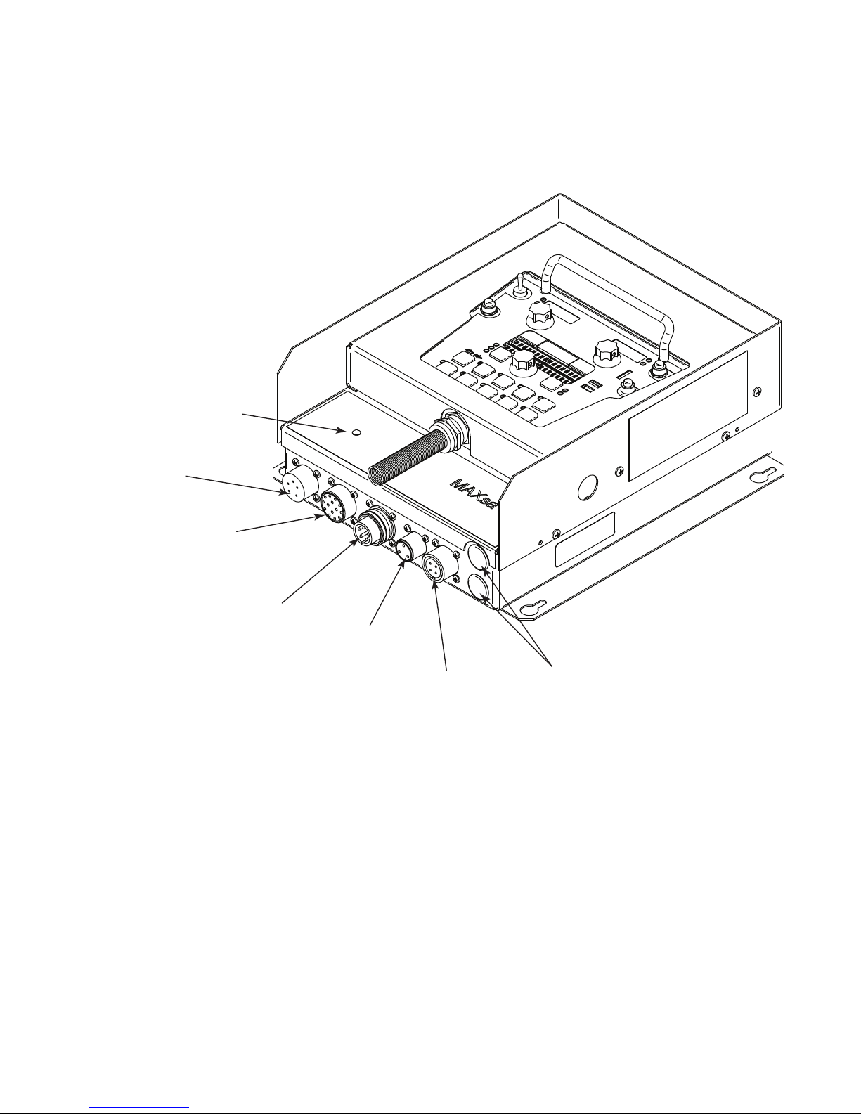
FIGURE A.1 - MAXsa™ 10 CONNECTIONS
ACCESS
HOLES
TC-3 TRAVEL CARRIAGE
CONNECTOR
FLUX HOPPER
CONNECTOR
POWER WAVE® AC/DC 1000 SD
ARCLINK CONNECTOR
PENDANT
CONNECTOR
MAXsa™ 22 or 29
WIRE DRIVE CONNECTOR (14-PIN)
STATUS
LIGHT
INSTALLATIONMAXSA™ 10 CONTROLLER
A-3
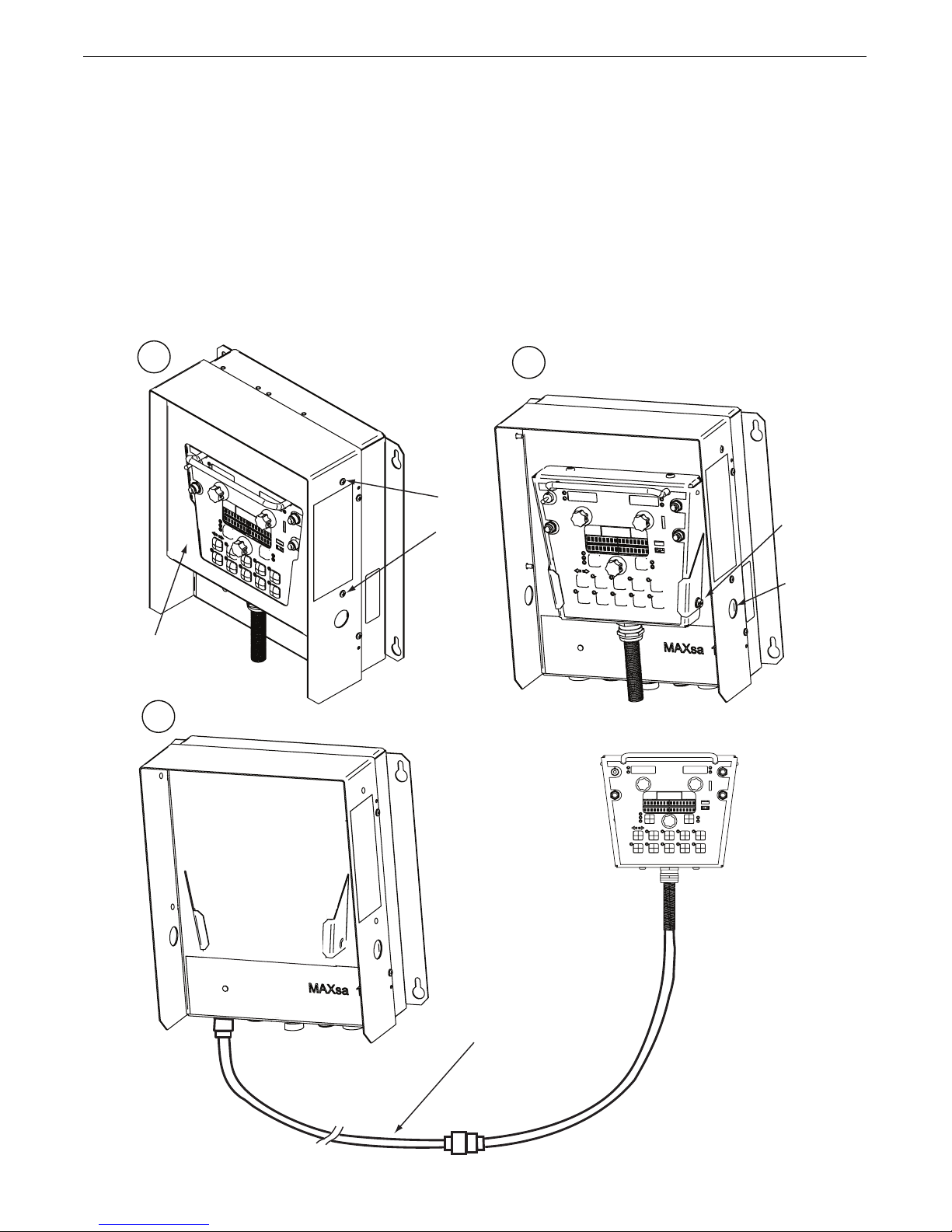
INSTALLATIONMAXSA™ 10 CONTROLLER
Cover Screws
(4 places)
Pendant
Screws
( 2 Places)
K1543-xx
or K2683-xx
Arclink Cable
(Optional)
Cover
F
ront View
C
over removed
Access
Hole
1
3
2
INTERFACING TO THE MAXsa™ 10 CONTROLLER
The MAXsa™ 10 CONTROLLER is a versatile controller. The User
Interface can be removed and used as a hand-held pendant. Most
circuits can be accessed through the screwless terminal strip.
The auxiliary relays can control standard Lincoln equipment, or
they can be used to control any other auxiliary equipment custom
controls. PLC interfacing to control starting, stopping, motion, etc,
Using the Controller as a Hand-held Pendant:
. Remove the 4 screws from the MAXsa™ 10 CONTROLLER that
1
hold the cover. See Figure A.2.
. Remove the 2 screws that hold the pendant in the brackets.
2
Use the access holes shown.
3. Extend the control cable as needed with an Arc Link cable of
appropriate length. See Figure A.2
can be accomplished with ease.
FIGURE A.2 - HAND HELD PENDANT
A-4
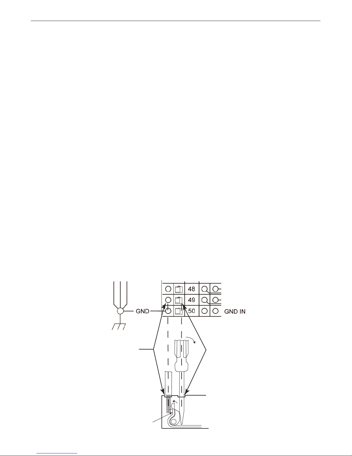
Auxiliary Input Power Connection Instructions
INSERT
WIRE HERE
INSERT SCREW
DRIVER HERE
# 1
# 3
REMOVE SCREW
DRIVER FROM CAGE
CLAMP HOLE.
# 2
CAGE CLAMP
VAC IN
NEUTRAL (31)
VAC IN
LINE (32)
se the appropriate size leads, at least 14 AWG – 2 wire with
U
ground.
1. Remove two Phillips Head screws on right side of front panel of
inged door to access terminal strip.
h
2. Remove a plug button and install a box connector to provide
strain relief for the input power leads.
3. Strip off 1/4”(6.4mm) of insulation from the leads and route
them through the strain relief
4. Locate the 4-terminal blocks, numbered #48, #49, and #50.
These are to be used to bring in auxiliary power. Terminal
block #50 is used for the input ground connection. This terminal block is color-coded green and yellow for easy identification. Terminal blocks #48 and #49 are to be used to connect
the input power circuit. (See Figure A.3).
5. Using a flat-head screwdriver with a blade dimension of
0.137"(3.5mm) x 0.020"(.51mm), insert the screwdriver into
the square hole next to the mounting hole to be used on the terminal strip. The screwdriver should be inserted until it bottoms
out. This opens the screwless cage clamping style wire insertion port. With the cage clamp opened insert the wire into the
round port until it bottoms out. While holding the lead securely,
remove the screwdriver from the terminal block. This closes the
cage clamp onto the lead holding it securely. Any open port on
blocks #48, #49, and #50 may be used.
INSTALLATIONMAXSA™ 10 CONTROLLER
Terminal blocks 48 and 49 are shipped connected to the contacts
f CR2 and CR3 by leads 531 and 532. These relay contacts are
o
also connected to the 4-pin Travel connector and the 3-pin Flux
connector located on the bottom of the MAXsa™ 10 CONTROLLER. CR1 is available for a separate customer connection,
ut it will turn ON and OFF with CR2. Therefore, if Lincoln auxiliary
b
equipment is to be used, connecting 115VAC to the terminal strip
is all that is required to power the devices.
NOTE: The contacts of CR1 are not connected to terminals #48
and #49 when shipped. Applying power to the #48 and #49
terminals will not transfer voltage to the CR1 relay.
Connect leads from the #48 terminal to the #4 terminal and
from the #49 terminal to the #3 terminal to supply power to
the common contacts of the relay.
Once input power is applied to the terminal strip, this voltage is
always on terminal strip blocks #3, #4 (if connected), #11, #17,
and #18. These are the inputs to the solid-state relay contacts.
Input voltage is also present on terminal strip blocks #7, #8 (if
connected), #15, #21, and #22 due to the N.C. contacts on the
relays. When the CR1 relay is energized, input power is transferred to terminal strip blocks #5 and #6 (if connected). When the
CR2 relay is energized, input power is transferred to terminal strip
block #13. When the CR3 relay is energized, input power is transferred to terminal strip blocks #19 and #20. CR1 and CR2 will be
turned ON and OFF at the same time.
FIGURE A.3
A-5
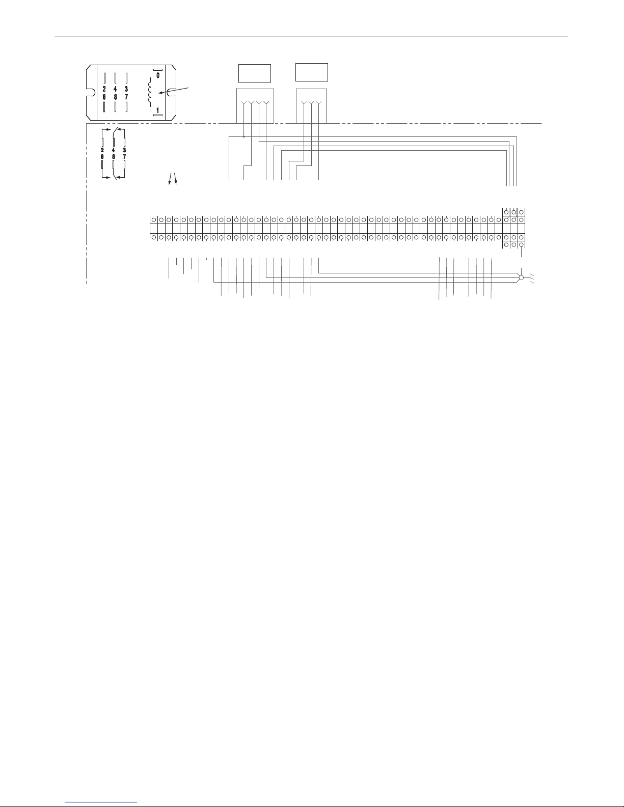
SWITCH GROUP #2 SUPPLY
3-PIN FLUX
RECEPTACLE
A
B
C
T
ERMINAL
STRIP
CR3 INPUT #8
852
855
858
859
CR3 NO #2
CR3 NO #6
CR3 NC #3
CR3 INPUT #4
CR1 INPUT #8
CR1 NO #2
CR1 NO #6
CR1 NC #3
FLUX GND
CR1 INPUT #4
CR3 NC #7
SHUTDOWN #2 SUPPLY
SHUTDOWN #1
SHUTDOWN #1 SUPPLY
532B-49
SWITCH GROUP #1 SUPPLY
START
FLUX FILL
GND IN
CR1 NC #7
TRAVEL #1 GND
531B-48
4-PIN TRAVEL
RECEPTACLE
A
B
C
D
CR2 INPUT #8
CR2 NO #2
CR2 NO #6
CR2 NC #3
CR2 INPUT #4
CR2 NC #7
TRAVEL #2 GND
GND
1
2
5
6
789
101112
131415
16
17
181920
212223
24
25
26
27
28
29
30
31
32
33
34
35
36
37
38
39
404142
434445
49
50
3
4
47
48
46
851
8510
859
CR1-4
CR1-8
CR1-2
CR1-6
CR1-3
CR1-7
GND-B
CR3-4
CR3-8
CR3-2
CR3-6
CR3-3
CR3-7
GND-A
CR2-4
CR2-8
CR2-2
CR2-6
CR2-3
CR2-7
531A-48
532A-49
GND-C
8511
SHUTDOWN #2
853
856
857
STOP
INCH FORWARD
INCH REVERSE
Numbers Refer to
Relay Terminals
CR1, CR2 CR3
Relays
IGURE A.4 - CONTROLLING NON-LINCOLN EQUIPMENT
F
INSTALLATIONMAXSA™ 10 CONTROLLER
CONTROLLING NON-LINCOLN AUXILIARY EQUIPMENT
Custom motion control and/or other auxiliary equipment can be powered using the terminal strip and relays. To use non-Lincoln motion
control and/or flux hoppers, follow instructions below. See Figure A.4.
1. Remove all input power to the MAXsa™ 10 CONTROLLER including
any auxiliary power supplies.
2. Remove the wire duct cover to gain access to the leads on the right
side of the terminal strip.
3. Remove a plug button from one of the .875” (22.2mm) access
holes on the bottom of the MAXsa™ 10 CONTROLLER control box.
Install a suitable strain relief to protect the leads. See Figure A.1.
4. Remove the leads going from the terminal strip to the correspond-
ing connectors, i.e. terminal strip blocks #11, #13, and #16 for the
4-pin TC-3 Travel Carriage or terminal strip blocks #19, #20, and
#23 for the 3-pin Automatic Flux Hopper. See the Wiring Diagram.
5. These loose leads can be taped and secured in the wire duct.
6. Any custom or non-Lincoln equipment can be powered by the nor-
mally open contacts from relays CR1, CR2, or CR3. The contacts
for CR1 are connected to the terminal strip blocks #3 through #8.
The contacts for CR2 are connected to terminal strip blocks #10
through #15. The contacts for CR3 are connected to terminal strip
blocks #17 through #22. See Figure A.3.
7. The supply voltage to power the devices is provided by the end
user. As shipped, the MAXsa™ 10 has the auxiliary supply blocks
(terminal strip blocks #48 and #49) connected to the CR2 relay and
CR3 relay inputs, respectively. When the end user connects a supply to the AUX blocks #48 and #49, this voltage will be jumpered to
the CR2 and CR3 relay inputs on terminal strip blocks #11, #17,
and #18.
NOTE: The CR1 relay is not connected to the AUX terminal strip
blocks; the customer must connect power to this relay if it is
to be used. See relay ratings listed earlier.
8. Connect input supply voltage per the Auxiliary Input Power
Connection Instructions listed earlier.
9. The relays can also be used to provide contact closure for any
interfacing signals out using the normally open contacts. An external auxiliary supply voltage would not be necessary to use the
relays as hard contact closure out signals.
NOTE: The CR1 relay as shipped does not have AUX leads connect-
ed to it. This relay operates as described above and has two
normally open / normally closed contacts that could be used
as a signal out when interfacing to PLC’s or custom controls.
CR1 and CR2 relay coils are in parallel and are BOTH turned ON
and OFF as determined by the Travel Options setting (P12 in the
Set-up Menu) as long as the TRAVEL MODE is set to AUTO. CR3
turns ON with the START command and OFF with the STOP
Command.
A-6
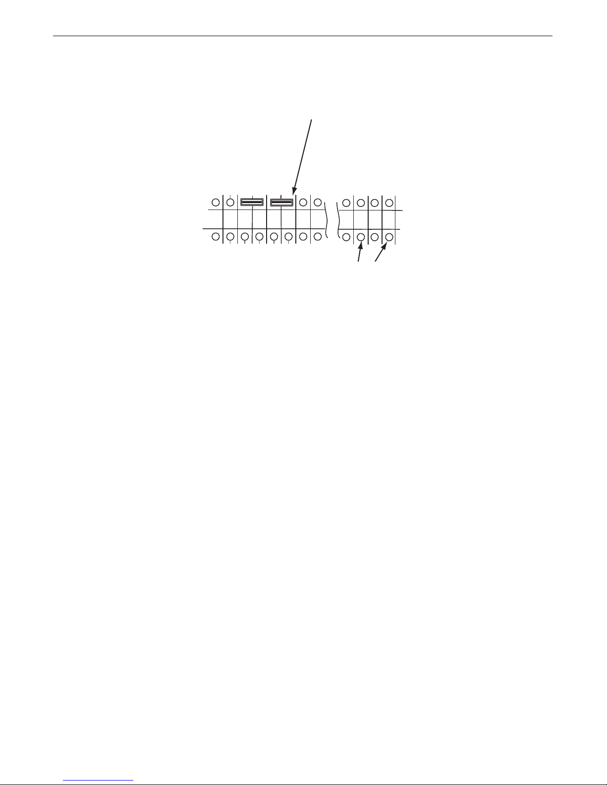
IGURE A.5 - SHUTDOWN AND STOP INPUTS
859
FLUX GND
CR3 NC #7
SHUTDOWN #2 SUPPLY
SHUTDOWN #1
SHUTDOWN #1 SUPPLY
22
23
24
25
26
27
8510
859
CR3-7
GND-C
8511
SHUTDOWN #2
Shorting
Jumper
Connect STOP
Input Here
39
41
40
SWITCH GROUP #1 SUPPLY
START
STOP
F
INSTALLATIONMAXSA™ 10 CONTROLLER
SHUTDOWN INPUTS
The MAXsa™ 10 CONTROLLER has two shutdown inputs available on the terminal strip. These are independent, normally
closed inputs that can be used for limit switches, PLC inputs,
etc, in order to shut down the welding operation for any reason.
Shutdown #1 is located on terminal strip blocks #24 and #25.
Shutdown #2 is located on terminal strip blocks #26 and #27.
1. Remove all input power to the MAXsa™ 10 CONTROLLER
including any auxiliary power supplies.
2. Remove the wire duct cover to gain access to the leads on
the right side of the terminal strip.
3. Remove one of the plug buttons located on the bottom of the
MAXsa™ 10 CONTROLLER control box and install a box connector to provide strain relief for the auxiliary control leads.
4. Connect the external shutdown circuit to either of the shutdown terminal blocks, #24 & #25, and/or #26 & #27. A normally closed circuit must be connected – the MAXsa™ 10
CONTROLLER will recognize an open circuit as a shutdown
command.
5. Remove the shorting jumpers imbedded in the center of the
terminal strip with a small screwdriver for the shutdown circuits to be used.
STOP INPUT
The MAXsa™ 10 CONTROLLER has a Stop Input available on the
terminal strip. The Stop Input will work just like pressing the
STOP Pushbutton. This circuit is in parallel with the STOP
Pushbutton located on the Switch Panel. Unlike the Shutdown
Inputs, which completely shutdown all welding and auxiliary
equipment, the STOP Input will allow all welding and auxiliary
motion to continue based on the END OPTIONS configurations in
the MAXsa™ 10 CONTROLLER. See Figure A.5.
1. Remove all input power to the MAXsa™ 10 CONTROLLER
including any auxiliary power supplies.
2. Remove the wire duct cover to gain access to the leads on
the right side of the terminal strip.
3. Remove one of the plug buttons located on the bottom of the
MAXsa™ 10 CONTROLLER control box and install a box connector to provide strain relief for the control leads.
4. Connect the external Stop Input circuit to terminal blocks #39
and #41.
NOTE: The STOP circuit only needs a momentary closure to be
recognized by the MAXsa™ 10 CONTROLLER.
When a shutdown input is received, all welding will stop and an
TROLLER. The shutdown circuit must be closed before resetting
error message will be displayed on the MAXsa™ 10 CON-
the Controller. To reset the system, the Mode Select Panel display will prompt the user to press the left Mode Select Panel
Pushbutton.
A-7
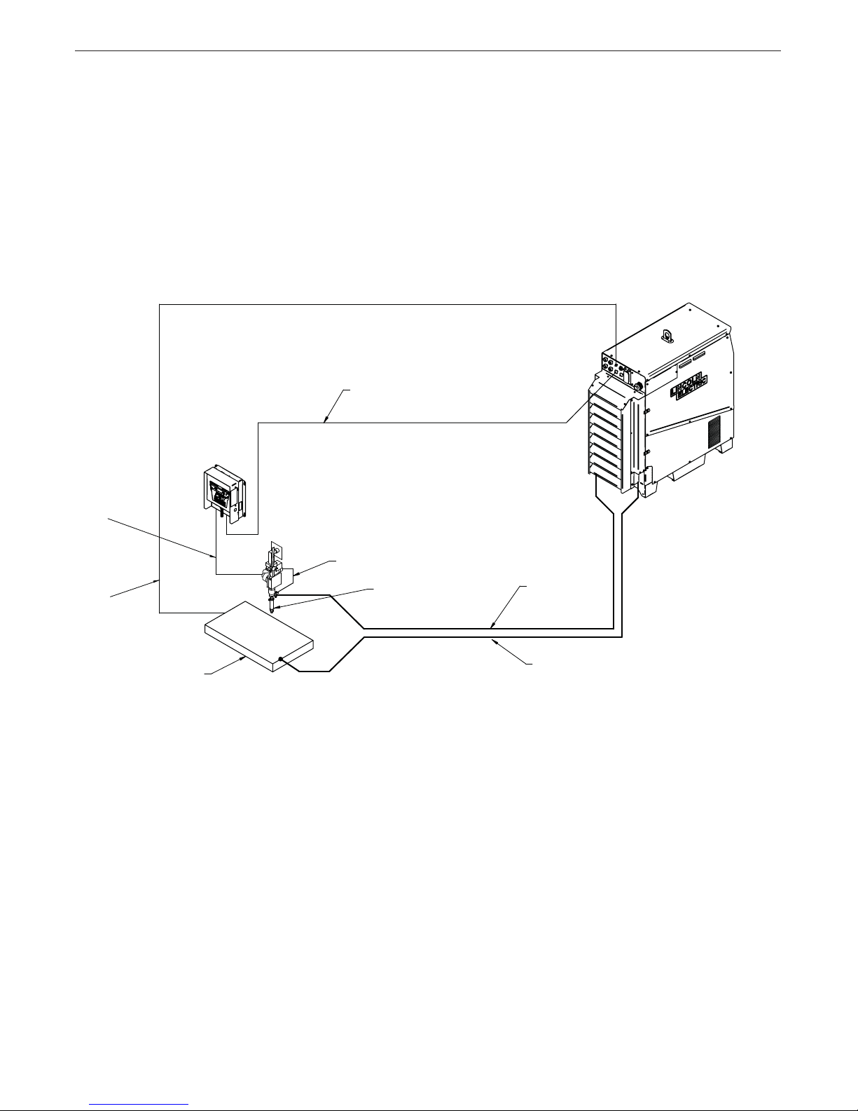
FIGURE A.6 - CONNECTION DIAGRAM - SINGLE ARC SYSTEM
INSTALLATIONMAXSA™ 10 CONTROLLER
K1785-XX
14-Pin Cable
K1811-XX
Sense Lead
K2814-X
MAXsa™ 10
Work
K2370-X
MAXsa™ 22
K1543-XX
or K2683-XX
Arclink Cable
67 Lead
K231-XX
Contact Nozzle
Electrode
Weld Cable
Work
Weld Cable
Power Wave
® AC/DC 1000SD
Congurations (Multi- Arc and Parelleled Power Sources)
are in the Power Wave® AC/DC 1000SD Operators Manual
Connection Diagrams for Additional
A-8
 Loading...