

Lincoln Electric LINC FEED 37, LINC FEED 38 Operator's Manual
LINC FEED 37 & 38
OPERATOR’S MANUAL
MANUALE OPERATIVO
BEDIENUNGSANLEITUNG
MANUAL DE INSTRUCCIONES
MANUEL D'UTILISATION
BRUKSANVISNING OG DELELISTE
GEBRUIKSAANWIJZING
BRUKSANVISNING
INSTRUKCJA OBSŁUGI
KÄYTTÖOHJE
IM1094
02/2008
Rev. 6
LINCOLN ELECTRIC BESTER S.A.
ul. Jana III Sobieskiego 19A, 58-260 Bielawa, Poland
www.lincolnelectric.eu

Declaration of conformity
Dichiarazione di conformità
Konformitätserklärung
Declaración de conformidad
Déclaration de conformité
Samsvars erklæring
Verklaring van overeenstemming
LINCOLN ELECTRIC BESTER S.A.
Declares that the welding machine:
Dichiara che Il generatore per saldatura tipo:
Erklärt, daß die Bauart der Maschine:
Declara que el equipo de soldadura:
Déclare que le poste de soudage:
Bekrefter at denne sveisemaskin:
Verklaart dat de volgende lasmachine:
LINC FEED 37 & 38
conforms to the following directives:
è conforme alle seguenti direttive:
den folgenden Bestimmungen entspricht:
es conforme con las siguientes directivas:
est conforme aux directives suivantes:
er i samsvar med følgende direktiver:
overeenkomt conform de volgende richtlijnen:
73/23/CEE, 89/336/CEE
and has been designed in compliance with the following
standards:
ed è stato progettato in conformità alle seguenti norme:
und in Übereinstimmung mit den nachstehenden normen
hergestellt wurde:
y ha sido diseñado de acuerdo con las siguientes
normas:
et qu'il a été conçu en conformité avec les normes:
og er produsert og testet iht. følgende standarder:
EN 60974-1, EN 60974-5, EN 60974-10
Försäkran om överensstämmelse
Deklaracja zgodności
Vakuutus yhteensopivuudesta
Försäkrar att svetsomriktaren:
Deklaruje, że spawalnicze źródło energii:
Vakuuttaa, että hitsauskone:
överensstämmer med följande direktiv:
spełnia następujące wytyczne:
täyttää seuraavat direktiivit:
en is ontworpen conform de volgende normen:
och att den konstruerats i överensstämmelse med
följande standarder:
i że zostało zaprojektowane zgodnie z wymaganiami
następujących norm:
ja on suunniteltu seuraavien standardien mukaan:
(2005)
Paweł Lipiński
Operations Director
LINCOLN ELECTRIC BESTER S.A., ul. Jana III Sobieskiego 19A, 58-260 Bielawa, Poland
II
12/05
Do not dispose of electrical equipment together with normal waste!
In observance of European Directive 2002/96/EC on Waste Electrical and Electronic Equipment (WEEE) and its
implementation in accordance with national law, electrical equipment that has reached the end of its life must be
English
Italiano
Deutsch
Español
Français
Norsk
Nederlandse
Svenska
Polski
Suomi
collected separately and returned to an environmentally compatible recycling facility. As the owner of the
equipment, you should get information on approved collection systems from our local representative.
By applying this European Directive you will protect the environment and human health!
Non gettare le apparecchiature elettriche tra i rifiuti domestici!
In ottemperanza alla Direttiva Europea 2002/96/CE sui Rifiuti di Apparechiature Elettriche ed Elettroniche (RAEE)
e la sua attuazione in conformità alle norme nazionali, le apparecchiature elettriche esauste devono essere
raccolte separatamente e restituite ad una organizzazione di riciclaggio ecocompatibile. Come proprietario
dell’apparecchiatura, Lei potrà ricevere informazioni circa il sistema approvato di raccolta, dal nostro
rappresentante locale.
Applicando questa Direttiva Europea Lei contribuirà a migliorare l’ambiente e la salute!
Werfen Sie Elektrowerkzeuge nicht in den Hausmüll!
Gemäss Europäischer Richtlinie 2002/96/EG über Elektro- und Elektronik- Altgeräte (Waste Electrical and
Electronic Equipment, WEEE) und Umsetzung in nationales Recht müssen verbrauchte Elektrowerkzeuge
getrennt gesammelt und einer umweltgerechten Wiederverwertung zugeführt werden. Als Eigentümer diese
Werkzeuges sollten sie sich Informationen über ein lokales autorisiertes Sammel- bzw. Entsorgungssystem
einholen.
Mit der Anwendung dieser EU Direktive tragen sie wesentlich zur Schonung der Umwelt und ihrer Gesundheit bei!
No tirar nunca los aparatos eléctricos junto con los residuos en general!.
De conformidad a la Directiva Europea 2002/96/EC relativa a los Residuos de Equipos Eléctricos o Electrónicos
(RAEE) y al acuerdo de la legislación nacional, los equipos eléctricos deberán ser recogidos y reciclados
respetando el medioambiente. Como propietario del equipo, deberá informar de los sistemas y lugares
apropiados para la recogida de los mismos.
Aplicar esta Directiva Europea protegerá el medioambiente y su salud!
Ne pas jeter les appareils électriques avec les déchets ordinaires!
Conformément à la Directive Européenne 2002/96/EC relative aux Déchets d' Équipements Électriques ou
Électroniques (DEEE), et à sa transposition dans la législation nationale, les appareils électriques doivent être
collectés à part et être soumis à un recyclage respectueux de l’environnement. En tant que propriétaire de
l’équipement, vous devriez vous informer sur les systèmes de collecte approuvés auprès nos représentants
locaux.
Appliquer cette Directive Européenne améliorera l’environnement et la santé!
Kast ikke elektriske artikler sammen med vanlig søppel.
I følge det europeiske direktivet for Elektronisk Søppel og Elektriske Artikler 2002/96/EC (Waste Electrical and
Electronic Equipment, WEEE) skal alt avfall kildesorteres og leveres på godkjente plasser i følge loven.
Godkjente retur plasser gis av lokale myndigheter.
Ved å følge det europeiske direktivet bidrar du til å bevare naturen og den menskelige helse.
Gooi elektrische apparatuur nooit bij gewoon afval!
Met inachtneming van de Europese Richtlijn 2002/96/EC met betrekking tot Afval van Elektrische en
Elektronische Apparatuur (Waste Electrical and Electronic Equipment, WEEE) en de uitvoering daarvan in
overeenstemming met nationaal recht, moet elektrische apparatuur, waarvan de levensduur ten einde loopt, apart
worden verzameld en worden ingeleverd bij een recycling bedrijf, dat overeenkomstig de milieuwetgeving
opereert. Als eigenaar van de apparatuur moet u informatie inwinnen over goedgekeurde verzamelsystemen van
onze vertegenwoordiger ter plaatse.
Door het toepassen van deze Europese Richtlijn beschermt u het milieu en ieders gezondheid!
Släng inte uttjänt elektrisk utrustning tillsammans med annat avfall!
Enligt Europadirektiv 2002/96/EC ang. Uttjänt Elektrisk och Elektronisk Utrustning (Waste Electrical and
Electronic Equipment, WEEE) och dess implementering enligt nationella lagar, ska elektrisk utrustning som tjänat
ut sorteras separat och lämnas till en miljögodkänd återvinningsstation. Som ägare till utrustningen, bör du skaffa
information om godkända återvinningssystem från dina lokala myndigheter.
Genom att följa detta Europadirektiv bidrar du till att skydda miljö och hälsa!
Nie wyrzucać osprzętu elektrycznego razem z normalnymi odpadami!
Zgodnie z Dyrektywą Europejską 2002/96/EC dotyczącą Pozbywania się zużytego Sprzętu Elektrycznego i
Elektronicznego (Waste Electrical and Electronic Equipment, WEEE) i jej wprowadzeniem w życie zgodnie z
międzynarodowym prawem, zużyty sprzęt elektryczny musi być składowany oddzielnie i specjalnie utylizowany.
Jako właściciel urządzeń powinieneś otrzymać informacje o zatwierdzonym systemie składowania od naszego
lokalnego przedstawiciela.
Stosując te wytyczne bedziesz chronił środowisko i zdrowie człowieka!
Älä hävitä sähkölaitteita sekajätteiden mukana!
Noudatettaessa Euroopan Unionin Direktiiviä 2002/96/EY Sähkölaite- ja Elektroniikkajätteestä ( WEEE ) ja
toteutettaessa sitä sopusoinnussa kansallisen lain kanssa, sähkölaite, joka on tullut elinkaarensa päähän pitää
kerätä erilleen ja toimittaa sähkö- ja elektroniikkaromujen keräyspisteeseen. Lisätietoja tämän tuotteen
käsittelystä, keräämisestä ja kierrätyksestä saa kunnan ympäristöviranomaisilta.
Noudattamalla tätä Euroopan Unionin direktiiviä, autat torjumaan kielteiset ynpäristö- ja terveysvaikutukset!
07/06
III

IV
THANKS! For having choosen the QUALITY of the Lincoln Electric products.
• Please Examine Package and Equipment for Damage. Claims for material damaged in shipment must be notified
immediately to the dealer.
• For future reference record in the table below your equipment identification information. Model Name, Code & Serial
Number can be found on the machine rating plate.
GRAZIE! Per aver scelto la QUALITÀ dei prodotti Lincoln Electric.
• Esamini Imballo ed Equipaggiamento per rilevare eventuali danneggiamenti. Le richieste per materiali danneggiati dal
trasporto devono essere immediatamente notificate al rivenditore.
• Per ogni futuro riferimento, compilare la tabella sottostante con le informazioni di identificazione equipaggiamento.
Modello, Codice (Code) e Matricola (Serial Number) sono reperibili sulla targa dati della macchina.
VIELEN DANK! Dass Sie sich für ein QUALITÄTSPRODUKT von Lincoln Electric entschieden haben.
• Bitte überprüfen Sie die Verpackung und den Inhalt auf Beschädigungen. Transportschäden müssen sofort dem Händler
gemeldet werden.
• Damit Sie Ihre Gerätedaten im Bedarfsfall schnell zur Hand haben, tragen Sie diese in die untenstehende Tabelle ein.
Typenbezeichnung, Code- und Seriennummer finden Sie auf dem Typenschild Ihres Gerätes.
GRACIAS! Por haber escogido los productos de CALIDAD Lincoln Electric.
• Por favor, examine que el embalaje y el equipo no tengan daños. La reclamación del material dañado en el transporte
debe ser notificada inmediatamente al proveedor.
• Para un futuro, a continuación encontrará la información que identifica a su equipo. Modelo, Code y Número de Serie los
cuales pueden ser localizados en la placa de características de su equipo.
MERCI! Pour avoir choisi la QUALITÉ Lincoln Electric.
• Vérifiez que ni l’équipement ni son emballage ne sont endommagés. Toute réclamation pour matériel endommagé doit
être immédiatement notifiée à votre revendeur.
• Notez ci-dessous toutes les informations nécessaires à l’identification de votre équipement. Le nom du Modèle ainsi que
les numéros de Code et Série figurent sur la plaque signalétique de la machine.
TAKK! For at du har valgt et KVALITETSPRODUKT fra Lincoln Electric.
• Kontroller emballsjen og produktet for feil eller skader. Eventuelle feil eller transportskader må umiddelbart rapporteres
dit du har kjøpt din maskin.
• For fremtidig referanse og for garantier og service, fyll ut den tekniske informasjonen nedenfor i dette avsnittet. Modell
navn, Kode & Serie nummer finner du på den tekniske platen på maskinen.
BEDANKT! Dat u gekozen heeft voor de KWALITEITSPRODUCTEN van Lincoln Electric.
• Controleert u de verpakking en apparatuur op beschadiging. Claims over transportschade moeten direct aan de dealer of
aan Lincoln electric gemeld worden.
• Voor referentie in de toekomst is het verstandig hieronder u machinegegevens over te nemen. Model Naam, Code &
Serienummer staan op het typeplaatje van de machine.
TACK! För att ni har valt en KVALITETSPRODUKT från Lincoln Electric.
• Vänligen kontrollera förpackning och utrustning m.a.p. skador. Transportskador måste omedelbart anmälas till
återförsäljaren eller transportören.
• Notera informationen om er utrustnings identitet i tabellen nedan. Modellbeteckning, code- och serienummer hittar ni på
maskinens märkplåt.
DZIĘKUJEMY! Za docenienie JASKOŚCI produktów Lincoln Electric.
• Proszę sprawdzić czy opakownie i sprzęt nie są uszkodzone. Reklamacje uszkodzeń powstałych podczas transportu
muszą być natychmiast zgłoszone do dostawcy (dystrybutora).
• Dla ułatwienia prosimy o zapisanie na tej stronie danych identyfikacyjnych wyrobów. Nazwa modelu, Kod i Numer
Seryjny, które możecie Państwo znaleźć na tabliczce znamionowej wyrobu.
KIITOS! Kiitos, että olet valinnut Lincoln Electric LAATU tuotteita.
• Tarkista pakkaus ja tuotteet vaurioiden varalta. Vaateet mahdollisista kuljetusvaurioista on ilmoitettava välittömästi
jälleenmyyjälle.
• Tulevaisuutta varten täytä alla oleva lomake laitteen tunnistusta varten. Mallin, Koodin ja Sarjanumeron voit löytää
konekilvestä.
Model Name, Modello, Typenbezeichnung, Modelo, Nom du modèle, Modell navn, Model Naam, Modellbeteckning, Nazwa
modelu, Mallinimi:
………………...…………………………….…………………………………………………………………………………………..
Code & Serial number, Code (codice) e Matricola, Code- und Seriennummer, Code y Número de Serie, Numéros de Code et
Série, Kode & Serie nummer, Code en Serienummer, Code- och Serienummer, Kod i numer Seryjny, Koodi ja Sarjanumero:
………………….……………………………………………….. …………………………………………………….……………..
Date & Where Purchased, Data e Luogo d’acquisto, Kaufdatum und Händler, Fecha y Nombre del Proveedor, Lieu et Date
d’acquisition, Kjøps dato og Sted, Datum en Plaats eerste aankoop, Inköpsdatum och Inköpsställe, Data i Miejsce zakupu,
Päiväys ja Ostopaikka:
…………………………………………………………………... ……………………….…………………………………………..
12/05

ENGLISH INDEX
Safety ............................................................................................................................................................................................... A-1
Installation and Operator Instructions ............................................................................................................................................... A-2
Electromagnetic Compatibility (EMC) ............................................................................................................................................. A-12
Technical Specifications ................................................................................................................................................................. A-12
INDICE ITALIANO
Sicurezza ......................................................................................................................................................................................... B-1
Installazione e Istruzioni Operative ................................................................................................................................................... B-2
Compatibilità Elettromagnetica (EMC) ............................................................................................................................................ B-12
Specifiche Tecniche ....................................................................................................................................................................... B-12
INHALTSVERZEICHNIS DEUTSCH
Sicherheitsmaßnahmen / Unfallschutz .............................................................................................................................................. C-1
Installation und Bedienungshinweise ................................................................................................................................................ C-2
Elektromagnetische Verträglichkeit (EMC) ...................................................................................................................................... C-12
Technische Daten .......................................................................................................................................................................... C-12
INDICE ESPAÑOL
Seguridad ......................................................................................................................................................................................... D-1
Instalación e Instrucciones de Funcionamiento................................................................................................................................. D-2
Compatibilidad Electromagnética (EMC) ........................................................................................................................................ D-12
Especificaciones Técnicas .............................................................................................................................................................. D-12
INDEX FRANÇAIS
Sécurité ............................................................................................................................................................................................ E-1
Installation et Instructions d'Utilisation .............................................................................................................................................. E-2
Compatibilité Electromagnétique (CEM) ......................................................................................................................................... E-12
Caractéristiques Techniques .......................................................................................................................................................... E-12
NORSK INNHOLDSFORTEGNELSE
Sikkerhetsregler ............................................................................................................................................................................... F-1
Installasjon og Brukerinstruksjon ...................................................................................................................................................... F-2
Elektromagnetisk Kompatibilitet (EMC) ........................................................................................................................................... F-12
Tekniske Spesifikasjoner ................................................................................................................................................................ F-12
NEDERLANDSE INDEX
Veiligheid.......................................................................................................................................................................................... G-1
Installatie en Bediening .................................................................................................................................................................... G-2
Elektromagnetische Compatibiliteit (EMC) ...................................................................................................................................... G-12
Technische Specificaties ................................................................................................................................................................ G-12
SVENSK INNEHÅLLSFÖRTECKNING
Säkerhetsanvisningar ....................................................................................................................................................................... H-1
Instruktioner för Installation och Handhavande ................................................................................................................................. H-2
Elektromagnetisk Kompatibilitet (EMC) ........................................................................................................................................... H-12
Tekniska Specifikationer ................................................................................................................................................................. H-12
SKOROWIDZ POLSKI
Bezpieczeństwo Użytkowania............................................................................................................................................................ I-1
Instrukcja Instalacji i Eksploatacji ....................................................................................................................................................... I-2
Kompatybilność Elektromagnetyczna (EMC) ................................................................................................................................... I-12
Dane Techniczne ............................................................................................................................................................................ I-12
SISÄLLYSLUETTELO
Turvallisuus ....................................................................................................................................................................................... J-1
Asennus ja Käyttöohjeet .................................................................................................................................................................... J-2
Elektromagneettinen Yhteensopivuus (EMC) .................................................................................................................................. J-12
Tekniset Tiedot ................................................................................................................................................................................ J-12
Spare Parts, Parti di Ricambio, Ersatzteile, Lista de Piezas de Recambio, Pièces de Rechange, Deleliste, Reserve Onderdelen,
Reservdelar, Wykaz Części Zamiennych, Varaosaluettelo ................................................................................................................... 1
Electrical Schematic, Schema Elettrico, Elektrische Schaltpläne, Esquema Eléctrico, Schéma Electrique, Elektrisk Skjema, Elektrisch
Schema, Elektriskt Kopplingsschema, Schemat Elektryczny, Sähkökaavio .......................................................................................... 5
Accessories, Accessori, Zubehör, Accesorios, Accessoires, Tilleggsutstyr, Accessores, Tillbehör, Akcesoria, Varusteet ..................... 7
V
Safety
11/04
WARNING
This equipment must be used by qualified personnel. Be sure that all installation, operation, maintenance and repair
procedures are performed only by qualified person. Read and understand this manual before operating this equipment.
Failure to follow the instructions in this manual could cause serious personal injury, loss of life, or damage to this
equipment. Read and understand the following explanations of the warning symbols. Lincoln Electric is not responsible
for damages caused by improper installation, improper care or abnormal operation.
WARNING: This symbol indicates that instructions must be followed to avoid serious personal injury,
loss of life, or damage to this equipment. Protect yourself and others from possible serious injury or
death.
READ AND UNDERSTAND INSTRUCTIONS: Read and understand this manual before operating
this equipment. Arc welding can be hazardous. Failure to follow the instructions in this manual could
cause serious personal injury, loss of life, or damage to this equipment.
ELECTRIC SHOCK CAN KILL: Welding equipment generates high voltages. Do not touch the
electrode, work clamp, or connected work pieces when this equipment is on. Insulate yourself from
the electrode, work clamp, and connected work pieces.
ELECTRICALLY POWERED EQUIPMENT: Turn off input power using the disconnect switch at the
fuse box before working on this equipment. Ground this equipment in accordance with local electrical
regulations.
ELECTRICALLY POWERED EQUIPMENT: Regularly inspect the input, electrode, and work clamp
cables. If any insulation damage exists replace the cable immediately. Do not place the electrode
holder directly on the welding table or any other surface in contact with the work clamp to avoid the
risk of accidental arc ignition.
ELECTRIC AND MAGNETIC FIELDS MAY BE DANGEROUS: Electric current flowing through any
conductor creates electric and magnetic fields (EMF). EMF fields may interfere with some
pacemakers, and welders having a pacemaker shall consult their physician before operating this
equipment.
CE COMPLIANCE: This equipment complies with the European Community Directives.
FUMES AND GASES CAN BE DANGEROUS: Welding may produce fumes and gases hazardous to
health. Avoid breathing these fumes and gases. To avoid these dangers the operator must use
enough ventilation or exhaust to keep fumes and gases away from the breathing zone.
ARC RAYS CAN BURN: Use a shield with the proper filter and cover plates to protect your eyes from
sparks and the rays of the arc when welding or observing. Use suitable clothing made from durable
flame-resistant material to protect you skin and that of your helpers. Protect other nearby personnel
with suitable, non-flammable screening and warn them not to watch the arc nor expose themselves to
the arc.
WELDING SPARKS CAN CAUSE FIRE OR EXPLOSION: Remove fire hazards from the welding
area and have a fire extinguisher readily available. Welding sparks and hot materials from the welding
process can easily go through small cracks and openings to adjacent areas. Do not weld on any
tanks, drums, containers, or material until the proper steps have been taken to insure that no
flammable or toxic vapors will be present. Never operate this equipment when flammable gases,
vapors or liquid combustibles are present.
WELDED MATERIALS CAN BURN: Welding generates a large amount of heat. Hot surfaces and
materials in work area can cause serious burns. Use gloves and pliers when touching or moving
materials in the work area.
SAFETY MARK: This equipment is suitable for supplying power for welding operations carried out in
an environment with increased hazard of electric shock.
A-1
CYLINDER MAY EXPLODE IF DAMAGED: Use only compressed gas cylinders containing the
correct shielding gas for the process used and properly operating regulators designed for the gas and
pressure used. Always keep cylinders in an upright position securely chained to a fixed support. Do
not move or transport gas cylinders with the protection cap removed. Do not allow the electrode,
electrode holder, work clamp or any other electrically live part to touch a gas cylinder. Gas cylinders
must be located away from areas where they may be subjected to physical damage or the welding
process including sparks and heat sources.
Installation and Operator Instructions
Read this entire section before installation or operation
of the machine.
Location and Environment
This machine will operate in harsh environments.
However, it is important that simple preventative
measures are followed to assure long life and reliable
operation.
• Do not place or operate this machine on a surface
with an incline greater than 15° from horizontal.
• Do not use this machine for pipe thawing.
• This machine must be located where there is free
circulation of clean air without restrictions for air
movement to and from the air vents. Do not cover
the machine with paper, cloth or rags when
switched on.
• Dirt and dust that can be drawn into the machine
should be kept to a minimum.
• This machine has a protection rating of IP23. Keep
it dry when possible and do not place it on wet
ground or in puddles.
• Locate the machine away from radio controlled
machinery. Normal operation may adversely affect
the operation of nearby radio controlled machinery,
which may result in injury or equipment damage.
Read the section on electromagnetic compatibility in
this manual.
• Do not operate in areas with an ambient
temperature greater than 40°C.
Duty cycle
The duty cycle of a welding machine is the percentage of
time in a 10 minute cycle at which the welder can
operate the machine at rated welding current.
Example: 60% duty cycle:
Welding for 6 minutes. Break for 4 minutes.
Refer to the Technical Specification section for more
information about the machine rated duty cycles.
Input Supply Connection
Check the input voltage, phase, and frequency of the
power source that will be connected to this wire feeder.
The allowable input voltage of the power source is
indicated on the rating plate of the wire feeder. Verify
the connection of grounding wires from the power source
to the input source.
Gas Connection
A gas cylinder must to be installed with a proper flow
regulator. Once a gas cylinder with a flow regulator has
been securely installed, connect the gas hose from the
regulator to the machine gas inlet connector. Refer to
point 8 of the images below. The wire feeder supports
all suitable shielding gases including carbon dioxide,
argon and helium at a maximum pressure of 5,0 bar.
The Linc Feed also includes an internal gas flow
regulator, showed at point 11 of the images below.
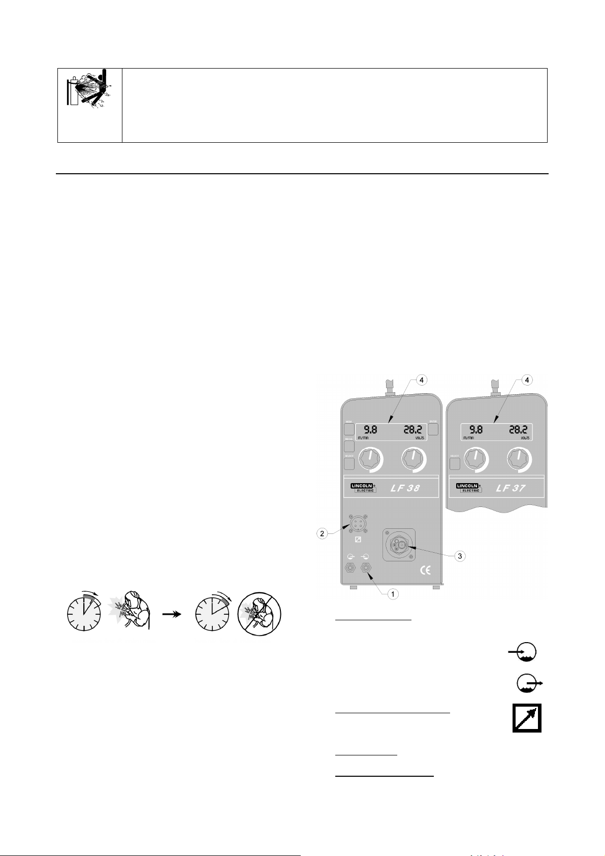
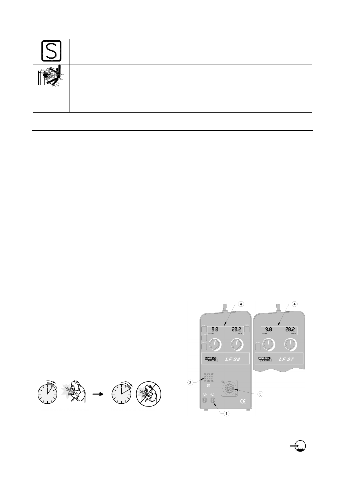
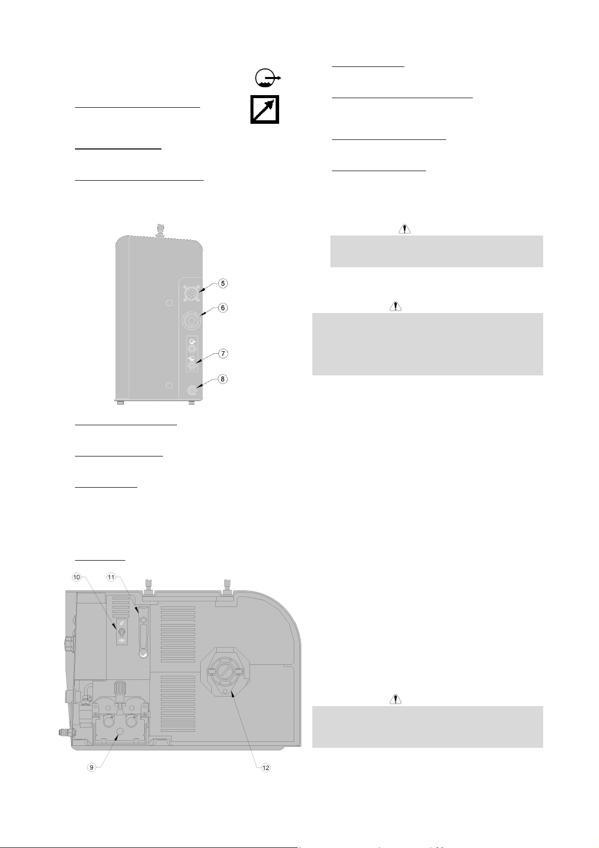
Output Connections
Refer to item 3 of the images below.
Controls and Operational Features
1. Water Connectors: Connections for water cooled
torches.
Warm water from torch.
Cool water to torch.
2. Remote Control Receptacle: If a remote
control is used, it will be connected to the
remote receptacle.
3. Euroconnector: Connect welding torches.
4. Digital Display Interface: Control of welding
parameters including Wire Feed Speed, Voltage,
A-2
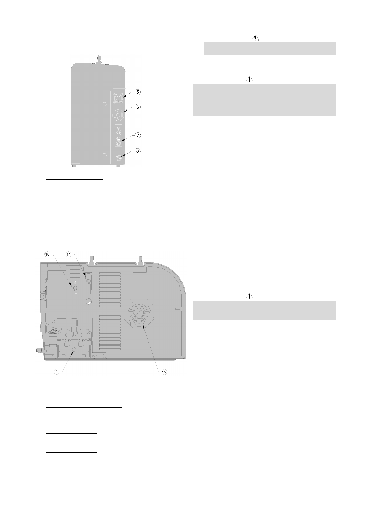
and Memory Recall. See sections A-G for further
details.
5. Amphenol Connection: 8-Pin connection to power
source.
6. Fast-Mate Adapter: Input power connection.
7. Water Connectors: If water cooled torches are
used, connect water lines from water cooler here.
Refer to torch and water cooler guidelines for
recommended cooling liquid and flow rates.
8. Gas Connector: Connection for gas line.
9. Wire Drive: 4-Roll wire drive compatible with 37mm
drive rolls.
10. Cold Inch / Gas Purge Control: This switch allows
gas flow or wire feeding without turning on output
voltage.
11. Gas Flow Regulator: Regulate flow between 0-25
LPM (liter/min.).
12. Wire Spool Support: Maximum 15kg spools.
Accepts plastic, steel and fiber spools onto 51mm
spindle. Also accepts Readi-Reel
included spindle adapter.
type spools onto
WARNING
The Linc Feed wire feeders must be used with the
door completely closed during welding.
Maintenance
WARNING
For any maintenance or repair operations it is
recommended to contact the nearest Technical Service
Center or Lincoln Electric. Maintenance or repairs
performed by unauthorized service centers or personnel
will null and void the manufacturer's warranty.
The frequency of the maintenance operations may vary
in accordance with the working environment where the
machine is placed.
Any noticeable damage should be reported immediately.
Routine maintenance
• Check condition of insulation and connections of the
work cables and input power supply cable.
• Remove the spatters from the welding gun nozzle.
Spatters could interfere with the shielding gas flow
to the arc.
• Check the welding gun condition: replace it, if
necessary.
• Check condition and operation of the cooling fan.
Keep clean its airflow slots.
Periodic maintenance
Perform the routine maintenance and, in addition:
• Keep the machine clean. Using a dry (and low
pressure) airflow, remove the dust from the external
case and from the cabinet inside.
• Check condition of all connections and change if
necessary.
• Check and tighten all screws.
WARNING
Mains supply network must be disconnected from the
machine before each maintenance and service. After
each repair, perform proper tests to ensure safety.
A-3
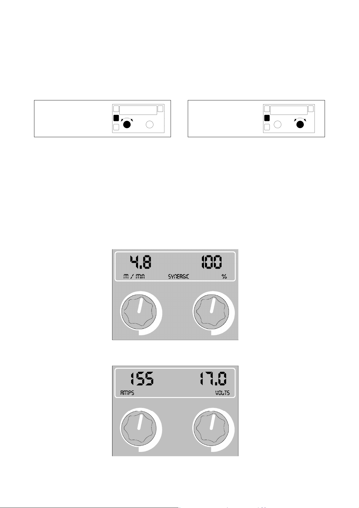
LF 37:
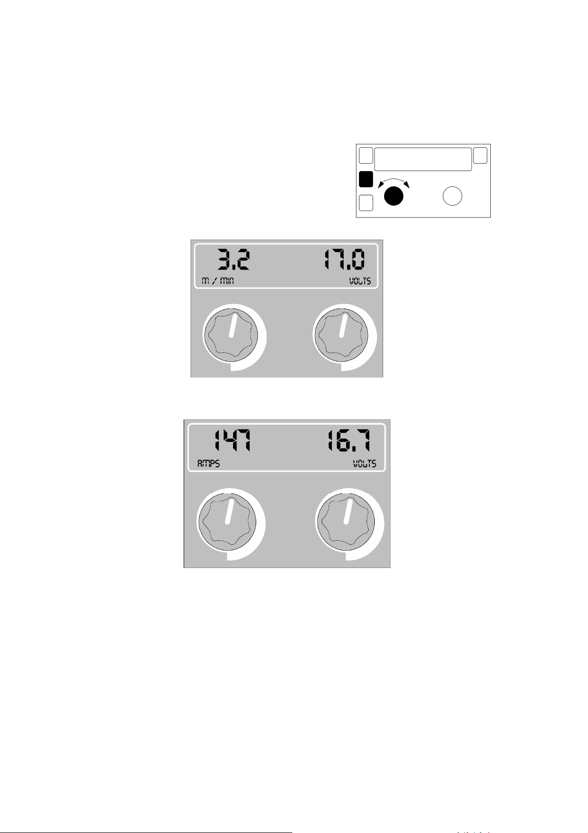
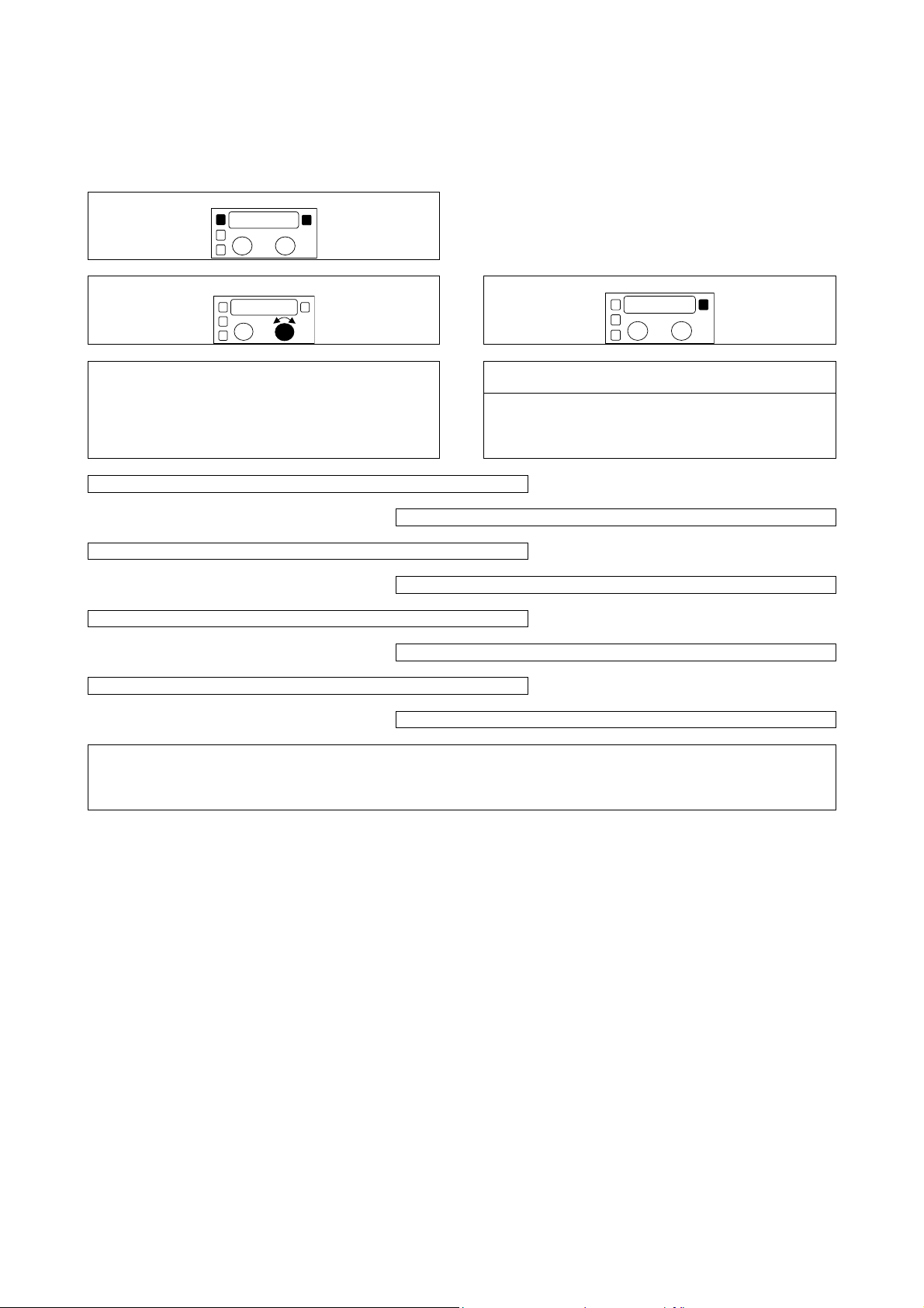
A. Non Synergic Welding Mode (CV Mode)
Description:
During Non Synergic (CV Mode) welding, the pre-setting of the welding parameters (Wire Feed Speed and Voltage) are
independent from one another.
Set-Up:
This machine is always in Non-Synergic Welding Mode
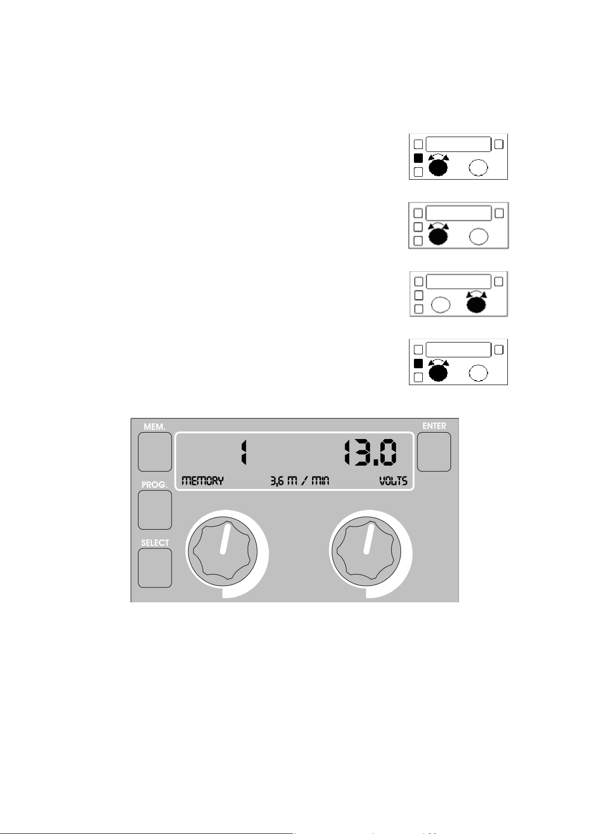
LF 38: While pressing the Prog button, rotate the left knob until
“NON SYNERGIC” appears on the display.
Before Welding (Pre-Set):
Pre-Set Wire Feed Speed
(Meters/Minute)
Adjust with left knob.
Pre-Set Welding Voltage
(V)
Adjust with right knob.
During Welding (Actual):
These actual values are displayed for 5 seconds after the weld has stopped. Press ENTER (LF 38 Only) to recall these
values.
Actual Welding Current
(A)
Actual Welding Voltage
(V)
A-4

B. Synergic Welding Mode (LF 38 only)
Description:
During Synergic welding, the wire feeder determines the optimal voltage characteristics based upon the selected wire
type and diameter. Only the wire feed speed needs to be regulated by the user. The user can then adjust the height of
the arc using the right knob. Once the arc height has been established, it will remain at the same level regardless of any
variation in the wire feed speed.
Set-Up:
While pressing the Prog
button, rotate the Left knob
and select from the
following:
While pressing the Prog
button, rotate the Right
knob and select the
appropriate wire
diameter:
Before welding (Pre-Set):
Pre-Set Wire Feed Speed
(Meters/Minute)
Adjust with left knob.
Steel 80/20
Stainless 98/2
Metal Cored 98/2
Flux Cored 80/20
Flux Cored CO2
AlMg 100% Arg
AlSi 100% Arg
Innershield NR-211MP
Innershield NR-232
Innershield NR-400
Innershield NS-3M
0.8, 1.0, 1.2 mm
0.8, 1.0, 1.2 mm
1.2, 1.6 mm
1.2, 1.6 mm
1.2, 1.6 mm
1.2, 1.6 mm
1.2, 1.6 mm
1.7, 2.0 mm
1.8, 2.0 mm
2.0 mm
2.0 mm
Pre-Set Relative Arc Height
100% is the baseline. This
value is often referred to as
Trim. Adjust with the Right
knob to increase/decrease arc
height.
During welding (Actual):
These actual values are displayed for 5 seconds after the weld has stopped. Press ENTER (LF 38 Only) to recall these
values.
Actual Welding Current
(A)
A-5
Actual Welding Voltage
(V)
KNOB 1:
KNOB 2:
welding. See crater sequenc
welding. See Hot/Soft start and crater
Pre-flow
Allows to set lower or higher welding
parameters to improve the bead shape at the
Allows to set higher or lower welding
parameters to improve the bead shape at the
will stop wh
Improve the protection of the bead before arc
: The crater sequence starts on the
ll last until the
Innershield V350PRO
YES or NO
with V350PRO generator.
Innershield
YES or NO
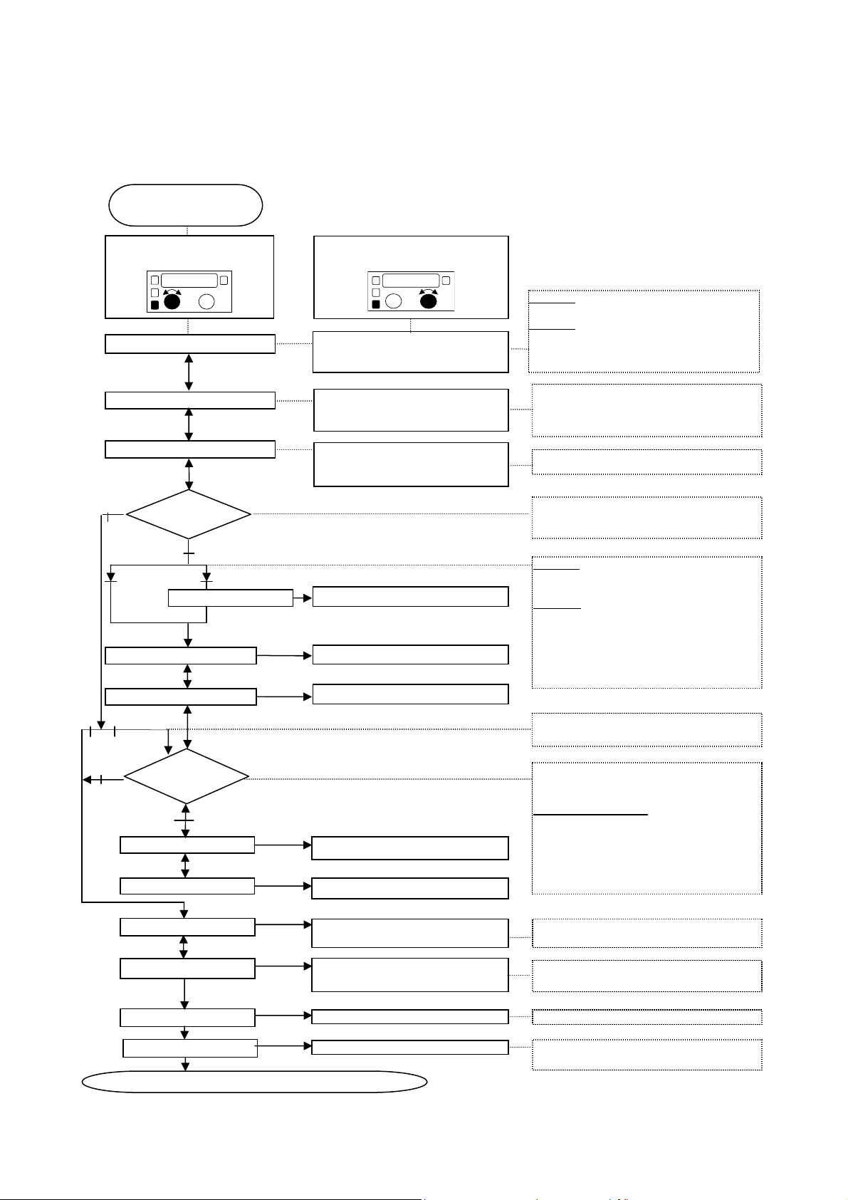
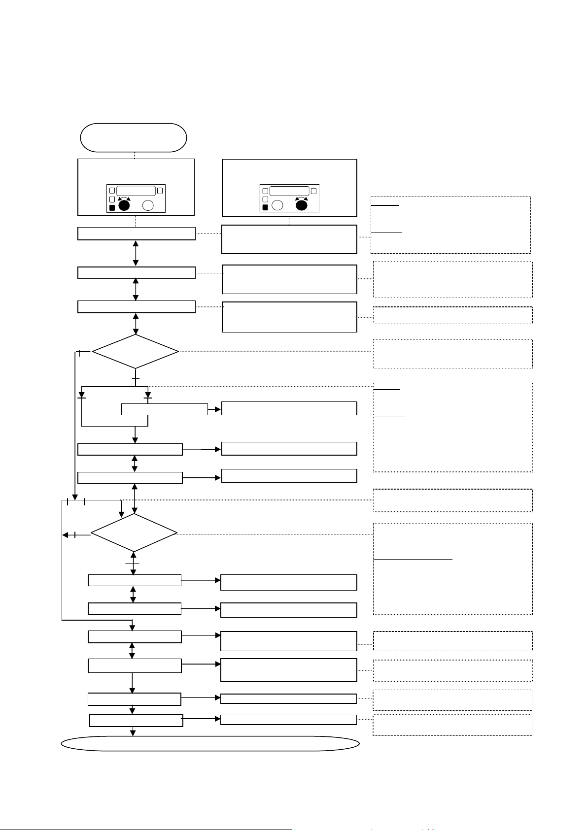
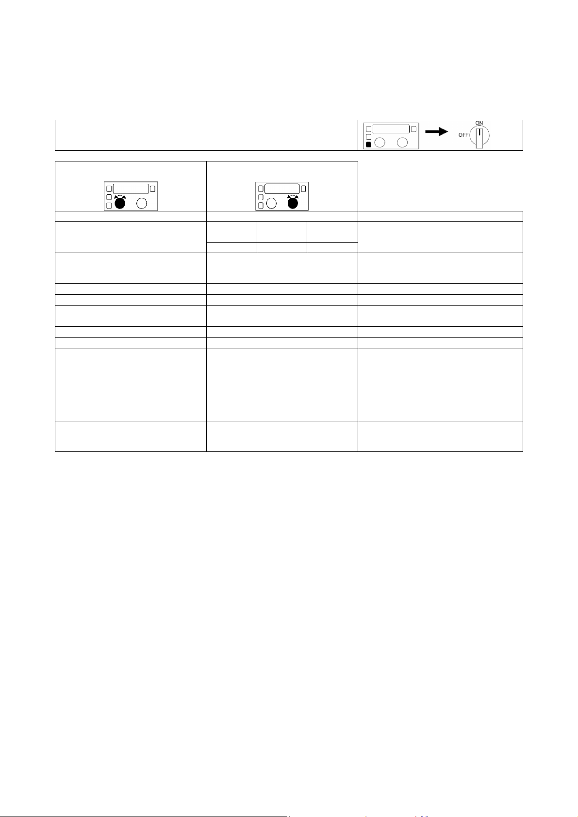
C. Selecting Welding Parameter
Description:
The following options can be regulated using the Select button and the procedure below: 2/4 Step Trigger, Burnback,
Run-In, Crater, Hot/Soft Start, Pre-Flow and Post-Flow.
Press SELECT button
Turn Right () or Left ()
Trigger Mode
Burnback
Run in
NO
Crater ?
4 Strokes
Crater Duration (sec)
Crater WFS
YES
2 Strokes
Turn Right() or Left ()
2 strokes / 4 strokes
Default Value: 2 strokes
0 to 1 second by step of 0,05s
Default Value: 0,1s
% of WFS (Wire Feed Speed)
Default Value: 60%
0 to 5 sec
Welding WFS (m/min)
2 strokes: Keep trigger pushed during
e below.
4 strokes: You can release the trigger while
sequence below.
Keeps the arc ignited for a short time while
the wire stops. Prevents the wire from
sticking in the weld puddle.
Speed of the wire before arc ignition.
end of the weld.
2 strokes: The crater sequence starts when
the trigger is released and stops when the
crater duration is over.
4 Strokes
third action of the trigger and wi
trigger is released. When the trigger is
released, the arc stops.
Crater Voltage
4 Strokes
2
NO
Release the "SELECT" button to exit this menu on any step.
Hot/Soft
Start ?
YES
Hot/Soft Start WFS
Post-flow
Welding Voltage (Volts)
Welding WFS (m/min)
Welding Voltage (Volts) Hot/Soft Start Voltage
0 to 2,5 seconds by steps of 0,5 s
0 to 10 seconds by steps of 0,5 s
Default Value: 0 s
Default Value: 2 s
Hot/Soft Start is available only in
4 strokes mode.
start of the weld.
In 4 strokes mode only: The Hot/Soft Start
sequence starts when the arc is ignited and
en the trigger is released. Then
the weld starts with the main welding
parameters.
ignition.
Improve the protection of the bead after arc
extinction.
Improves Innershield welding performance.
Improves Innershield welding performance
A-6
KNOB 1:
"ENTER"
"ENTER"
WRITE into memory:
parameters allready saved
ERASE m
emory:
parameters allready saved
WRITE memory:
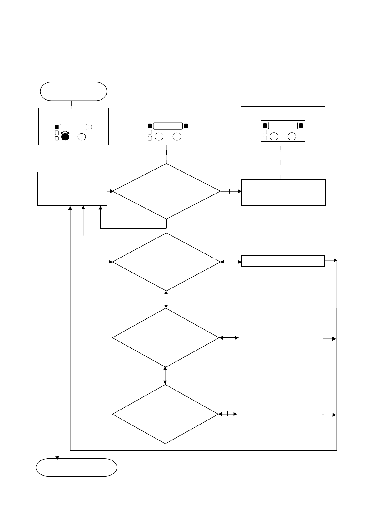
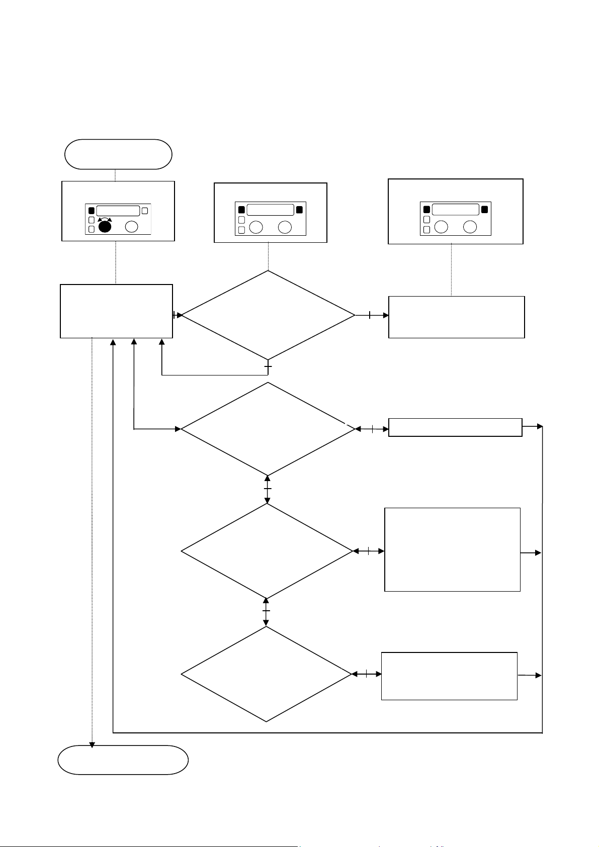
D. Memory Function - Saving, Reading and Erasing (LF 38 Only)
Description:
The Memory function can be used to recall up to 10 specific sets of welding parameters defined by the user. Once the
welding parameters have been defined, the following steps can be taken to write these parameters to memory.
Press the MEM button
Turn Right() or Left ()
Select Memory # (status):
- Used
- Free
From 1 to 10
Button
Button
Status
"Free"
WRITE ?
Save the welding
parameters into the
selected memory #.
YES
The status of the memory
becomes "Used".
NO
READ ?
You can read the welding
into the selected memory.
YES
READ memory
Release "MEM" button to exit.
NO
ERASE ?
Delete the welding
into the selected memory
NO
WRITE ?
Save the welding
parameters into the
selected memory #.
YES
YES
If you confirm ERASE by pushing
the "ENTER" button, then all the
welding parameters will be
deleted and the memory status
will become "Free".
You will overwrite the new
welding parameters in the
choosen memory #.
A-7
Prog
“RECALL MEMORY”
Prog
Non-Synergic Voltage
Synergic
Prog
E. Memory Function - Recalling Memory (LF 38 Only)
Description:
The saved Memory configurations can be recalled.
Set-Up:
While pressing the
appears on the display.
Selection:
Release the
memory configurations. Only the memory locations that have been used will be
available. Once selected, begin welding.
Welding:
While welding in Memory Mode, the
Trim values can be varied approximately 5% using the right knob. This allows for
fine adjustment of the welding characteristics.
To Exit:
To return to Non-Synergic or Synergic welding, press the
the left knob until the proper parameter appears. See sections A and B for further
details.
button, rotate the left knob until
button, then rotate the left knob to scroll through the saved
or the
button and rotate
Memory Screen Example:
A-8

Mem
Enter
Enter
YES
F. Memory Function - Locking / Unlocking Memory (LF 38 Only)
Description:
The Memory values can be locked / unlocked with a 4-digit code.
Press
Knob 2: Turn Right () or Left ()
Select 1st Digit of your code
Select 2nd Digit of your code
Select 3rd Digit of your code
Select 4th Digit of your code
&
Lock
Or
Unlock
Confirm 1st Digit
Confirm 2nd Digit
Confirm 3rd Digit
Confirm 4th Digit
Button
NO
YES
Exit to:
Locked Memory Mode
Or
Unlocked Memory Mode
Confirm NO to Exit this menu
Confirm
to Enter the menu:
Lock
Unlock
Or
A-9

Select
Knob 1:
Knob 2:
Choice of the con
figuration
Choice
Function
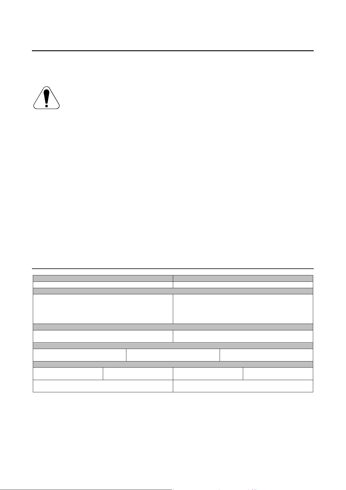
G. Configuration Menu
Description:
This hidden menu allows you to change the Machine Configuration.
To enter the set-up menu, press the
time Switch ON the machine.
Turn right or left
• LANGUAGE
• ACCELERATION
• PRODUCT TYPE
• SN
• MAINTENANCE
• CALIBRATION
• PROGRAM LEVEL
• RESET
• EXIT
pushbutton and at the same
Turn right or left
English Spanish Dutch Select the language you want to use.
Italian French Swedish
German Norwegian Polish
From 1 to 3
Standard value: 2
Not used
Not used
YES / NO
YES / NO
Not used
YES / NO
YES / NO
Value used to determine the
acceleration of the wire between the
"Cold inch WFS" and the "Welding
WFS".
Shows Product Type LF 37 or LF 38.
Shows Product Serial Number.
Answer NO or contact Lincoln
representative.
Answer NO.
Shows Program level of the Wire
Feeder.
If YES, you will:
• Erase all the memories and their
status will become "empty".
• Unlock the Recall memory mode if it
was locked.
• Restore all the parameters to their
“DEFAULT” values.
If YES, Press Select to Exit and save the
changes above.
A-10

Message
Description
Misadjustment(s)
Corrective Action
Unstable Welding
Wire Feed Jam
Water Flow Too Low
Water Flow Detected
Error messages:
Voltage
The generator is unable to
deliver the pre-set value
(voltage) requested by the
wire feeder.
It can appears:
1. During welding:
Motor is at maximum
power and is not able to
maintain the pre-set WFS
value.
The wire feeder has
detected:
• No water flow.
• Too low water flow
(less than 0.7
liter/min).
The wire feeder has
detected water flow while
the setting in select menu
is water cooler “no”.
• Check that welding pre-set
parameters (WFS and
Voltage) matches the
application (wire diameter,
thickness, gas…).
• Check the polarity switch
position of the generator
correspond to the polarity
of the wire feeder
connection.
• Check the remote control
switch of the generator set
on “Remote” position.
• Check if pre-set
parameters are not above
the specified limit of the
generator.
• Verify wire can move freely
in cable.
• Verify spool brake is not
set too high.
• Check if the water cooler is
on and filled up with
coolant.
• Check the water circuit
including water cooled
torch connection.
• The setting of water cooler
is wrong in the select
menu.
Note: In this case, flow meter
protection is not used.
• Adjust parameters.
• Correct polarity switch
position and wire feeder
polarity connection.
• Select “remote” position.
• Reduce the parameters or
use an higher rating
generator.
• Clean or replace the liner.
• Adjust spool brake.
• Fill up and switch on water
cooler.
• Remove blockage in water
circuit.
• Select the correct setting of
the water cooler in select
menu.
A-11
INPUT VOLTAGE
WIRE FEED SPEED
RATED OUTPUT AT 40°C
OUTPUT RANGE
WIRE SIZES (mm)
PHYSICAL DIMENSIONS
Electromagnetic Compatibility (EMC)
This machine has been designed in accordance with all relevant directives and standards. However, it may still generate
electromagnetic disturbances that can affect other systems like telecommunications (telephone, radio, and television) or
other safety systems. These disturbances can cause safety problems in the affected systems. Read and understand
this section to eliminate or reduce the amount of electromagnetic disturbance generated by this machine.
This machine has been designed to operate in an industrial area. To operate in a domestic area it is
necessary to observe particular precautions to eliminate possible electromagnetic disturbances. The
operator must install and operate this equipment as described in this manual. If any electromagnetic
disturbances are detected the operator must put in place corrective actions to eliminate these disturbances
with, if necessary, assistance from Lincoln Electric.
Before installing the machine, the operator must check the work area for any devices that may malfunction because of
electromagnetic disturbances. Consider the following.
• Input and output cables, control cables, and telephone cables that are in or adjacent to the work area and the
machine.
• Radio and/or television transmitters and receivers. Computers or computer controlled equipment.
• Safety and control equipment for industrial processes. Equipment for calibration and measurement.
• Personal medical devices like pacemakers and hearing aids.
• Check the electromagnetic immunity for equipment operating in or near the work area. The operator must be sure
that all equipment in the area is compatible. This may require additional protection measures.
• The dimensions of the work area to consider will depend on the construction of the area and other activities that are
taking place.
Consider the following guidelines to reduce electromagnetic emissions from the machine.
• Connect the machine to the input supply according to this manual. If disturbances occur if may be necessary to take
additional precautions such as filtering the input supply.
• The output cables should be kept as short as possible and should be positioned together. If possible connect the
work piece to ground in order to reduce the electromagnetic emissions. The operator must check that connecting
the work piece to ground does not cause problems or unsafe operating conditions for personnel and equipment.
• Shielding of cables in the work area can reduce electromagnetic emissions. This may be necessary for special
applications.
11/04
Technical Specifications
42 Vac 1.5-20 m/min
Duty Cycle
(based on a 10 min. period)
100%
60%
Welding Current Range
5-500 A
Solid wires
0.6 to 1.6
Height
356 mm
Operating Temperature
–10°C to +40°C
Width
188 mm
Cored wires
1.0 to 2.0
Maximum Open Circuit Voltage
Length
534 mm
Output Current
320 A
400 A
113 Vdc or Vac peak
Aluminium wires
1.0 to 1.6
Weight
16 Kg
Storage Temperature
-25°C to +55°C
A-12
Sicurezza
11/04
AVVERTENZA
Questa macchina deve essere impiegata solo da personale qualificato. Assicuratevi che tutte le procedure di
installazione, impiego, manutenzione e riparazione vengano eseguite solamente da persone qualificate. Leggere e
comprendere questo manuale prima di mettere in funzione la macchina. La mancata osservanza delle istruzioni di
questo manuale può provocare seri infortuni, anche mortali, alle persone, o danni alla macchina. Leggere e
comprendere le spiegazioni seguenti sui simboli di avvertenza. La Lincoln Electric non si assume alcuna responsabilità
per danni conseguenti a installazione non corretta, incuria o impiego in modo anormale.
AVVERTENZA: Questo simbolo indica che occorre seguire le istruzioni per evitare seri infortuni,
anche mortali, alle persone o danni a questa macchina. Proteggete voi stessi e gli altri dalla
possibilità di seri infortuni anche mortali.
LEGGERE E COMPRENDERE LE ISTRUZIONI: Leggere e comprendere questo manuale prima di
far funzionare la macchina. La saldatura ad arco può presentare dei rischi. La mancata osservanza
delle istruzioni di questo manuale può provocare seri infortuni, anche mortali, alle persone o danni alla
macchina.
LA FOLGORAZIONE ELETTRICA E’ MORTALE: Le macchine per saldatura generano tensioni
elevate. Non toccate l’elettrodo, il morsetto di massa o pezzi da saldare collegati alla macchina
quando la macchina è accesa. Mantenetevi isolati elettricamente da elettrodo, morsetto e pezzi
collegati a questo.
MACCHINA CON ALIMENTAZIONE ELETTRICA: Togliere l’alimentazione con l’interruttore ai fusibili
prima di svolgere operazioni su questa macchina. Mettere la macchina a terra secondo le normative
vigenti.
MACCHINA CON ALIMENTAZIONE ELETTRICA: Ispezionare periodicamente i cavi di
alimentazione, all’elettrodo e al pezzo. Se si riscontrano danni all’isolamento sostituire
immediatamente il cavo. Non posare la pinza portaelettrodo direttamente sul banco di saldatura o
qualsiasi altra superficie in contatto con il morsetto di massa per evitare un innesco involontario
dell’arco.
I CAMPI ELETTRICI E MAGNETICI POSSONO ESSERE PERICOLOSI: Il passaggio di corrente
elettrica in un conduttore produce campi elettromagnetici. Questi campi possono interferire con alcuni
cardiostimolatori ("pacemaker") e i saldatori con un cardiostimolatore devono consultare il loro medico
su possibili rischi prima di impiegare questa macchina.
CONFORMITÀ CE: Questa macchina è conforme alle Direttive Europee.
FUMI E GAS POSSONO ESSERE PERICOLOSI: La saldatura può produrre fumi e gas dannosi alla
salute. Evitate di respirare questi fumi e gas. Per evitare il pericolo l’operatore deve disporre di una
ventilazione o di un'estrazione di fumi e gas che li allontanino dalla zona in cui respira.
I RAGGI EMESSI DALL’ARCO BRUCIANO: Usate una maschera con schermatura adatta a
proteggervi gli occhi da spruzzi e raggi emessi dall’arco mentre saldate o osservate la saldatura.
Indossare indumenti adatti in materiale resistente alla fiamma per proteggere il corpo, sia vostro che
dei vostri aiutanti. Le persone che si trovano nelle vicinanze devono essere protette da schermature
adatte, non infiammabili, e devono essere avvertite di non guardare l’arco e di non esporvisi.
GLI SPRUZZI DI SALDATURA POSSONO PROVOCARE INCENDI O ESPLOSIONI: Allontanare
dall'area di saldatura quanto può prendere fuoco e tenere a portata di mano un estintore. Gli spruzzi
o altri materiali ad alta temperatura prodotti dalla saldatura attraversano con facilità eventuali piccole
aperture raggiungendo le zone vicine. Non saldare su serbatoi, bidoni, contenitori o altri materiali fino
a che non si sia fatto tutto il necessario per assicurarsi dell'assenza di vapori infiammabili o nocivi.
Non impiegare mai questa macchina se vi è presenza di gas e/o vapori infiammabili o combustibili
liquidi.
I MATERIALI SALDATI BRUCIANO: Il processo di saldatura produce moltissimo calore. Ci si può
bruciare in modo grave con le superfici e materiali caldi della zona di saldatura. Impiegare guanti e
pinze per toccare o muovere materiali nella zona di saldatura.
B-1
MARCHIO DI SICUREZZA: Questa macchina è adatta a fornire energia per operazioni di saldatura
svolte in ambienti con alto rischio di folgorazione elettrica.
LE BOMBOLE POSSONO ESPLODERE SE SONO DANNEGGIATE: Impiegate solo bombole
contenenti il gas compresso adatto al processo di saldatura utilizzato e regolatori di flusso, funzionanti
regolarmente, progettati per il tipo di gas e la pressione in uso. Le bombole vanno tenute sempre in
posizione verticale e assicurate con catena ad un sostegno fisso. Non spostate le bombole senza il
loro cappello di protezione. Evitate qualsiasi contatto dell’elettrodo, della sua pinza, del morsetto di
massa o di ogni altra parte in tensione con la bombola del gas. Le bombole gas vanno collocate
lontane dalle zone dove possano restare danneggiate dal processo di saldatura con relativi spruzzi e
da fonti di calore.
Installazione e Istruzioni Operative
Leggere tutta questa sezione prima di installare e
impiegare la macchina.
Collocazione e ambiente
Questa macchina è in grado di funzionare in ambienti
difficili. E’ comunque importante seguire delle semplici
misure di prevenzione per garantirne una lunga durata e
un funzionamento affidabile.
• Non collocare o impiegare la macchina su superfici
inclinate più di 15° rispetto all’orizzontale.
• Non usare questa macchina per sgelare tubi.
• La macchina va collocata ove vi sia una circolazione
di aria pulita senza impedimenti al suo movimento in
entrata e uscita dalle feritoie. Non coprire la
macchina con fogli di carta, panni o stracci quando
è accesa.
• Tenere al minimo polvere e sporco che possano
entrare nella macchina.
• Questa macchina ha una protezione di grado IP23.
Tenetela più asciutta possibile e non posatela su
suolo bagnato o dentro pozzanghere.
• Disponete la macchina lontana da macchinari
controllati via radio. Il suo funzionamento normale
può interferire negativamente sul funzionamento di
macchine controllate via radio poste nelle vicinanze,
con conseguenze di infortuni o danni materiali.
Leggete la sezione sulla compatibilità
elettromagnetica di questo manuale.
• Non impiegate la macchina in zone ove la
temperatura ambiente supera i 40°C.
Fattore d’intermittenza
Il fattore d’intermittenza di una macchina per saldatura è
la percentuale di tempo su un periodo di 10 minuti
durante la quale la macchina può esser fatta funzionare
alla corrente nominale.
Esempio: fattore di intermittenza del 60%
Collegamento all’alimentazione
Controllare tensione, numero di fasi e frequenza del
generatore che verrà collegato al trainafilo. La tensione
ammissibile per l’alimentazione dal generatore è indicata
sulla targhetta dati del trainafilo. Verificare il
collegamento del cavo di terra dal generatore alla sua
fonte di alimentazione.
Collegamento del gas
Installare una bombola gas munita di regolatore di flusso
adeguato. Una volta fissato bene in posto bombola e
regolatore di flusso, collegare il tubo gas dal regolatore
al connettore di ingresso gas sulla macchina. Far
riferimento al punto 8 dei disegni sottostanti. Questo
trainafilo supporta tutti i tipi di gas di protezione, inclusi
CO2, argon ed elio ad una pressione massima di 5.0 bar.
Il Linc Feed dispone inoltre al suo interno di un
regolatore di flusso del gas, mostrato al punto 11 dei
disegni sottostanti.
Collegamenti in uscita
Far riferimento al punto 3 dei disegni sottostanti.
Comandi e caratteristiche operative
6 minuti di saldatura. 4 minuti di interruzione.
Ulteriori informazioni sui fattori di intermittenza nominali
della macchina si trovano nella sezione Specifiche
Tecniche.
1. Connettori acqua: Collegamenti per torce
raffreddate ad acqua.
Acqua calda dalla torcia.
B-2
Acqua fredda verso la torcia.
2. Presa per comando a distanza: Se si
impiega un comando a distanza va
collegato a questa presa.
3. Connettore tipo Euro: Collegamento per le torce di
saldatura.
4. Interfaccia per il display digitale: Controllo dei
parametri di saldatura compresi Velocità filo,
Tensione, e Richiamo dalla Memoria. Vedere altri
dettagli nelle Sezioni A-G.
5. Collegamento Amphenol: Collegamento a 8 pin con
il generatore.
6. Adattatore Fast-Mate: Collegamento
dell’alimentazione elettrica.
7. Attacchi acqua: Quando si impiegano torce
raffreddate ad acqua, le linee dell’acqua dal gruppo
di raffreddamento vanno collegate qui. Fare
riferimento ai manuali della torcia e dell’unità di
raffreddamento per il tipo di liquido di
raffreddamento e valori di flusso raccomandati.
8. Attacco gas: Collegamento per la linea del gas.
9. Gruppo Trainafilo: Gruppo per 4 rulli motori adatto
a rulli da 37 mm.
10. Comando Filo Freddo/Spurgo Gas: Questo
commutatore permette di avere flusso di gas o
avanzamento filo senza dare tensione in uscita.
11. Regolatore di flusso del gas: Regolazione flusso fra
0 e 25 litri al minuto.
12. Sostegno porta-bobine: Per bobine di peso
massimo 15 kg. Accetta porta-bobine di plastica,
acciaio e fibra su un aspo portabobine da 51mm.
Accetta inoltre porta-bobine tipo Readi-Reel con
un adattatore incluso.
AVVERTENZA
I trainafilo Linc Feed devono essere impiegati
tenendo completamente chiuso lo sportello durante
la saldatura.
Manutenzione
AVVERTENZA
Per ogni operazione di manutenzione o riparazione si
raccomanda di rivolgersi al più vicino centro di
assistenza tecnica della Lincoln Electric. Manutenzioni o
riparazioni effettuate da personale o centri di servizio
non autorizzati fanno decadere la garanzia del
fabbricante.
La frequenza delle operazioni di manutenzione può
essere variata in funzione dell’ambiente in cui la
macchina si trova a lavorare.
Qualsiasi danno venga notato va immediatamente
riferito a chi di dovere.
Manutenzione corrente
• Controllare le condizioni dell’isolamento ed i
collegamenti dei cavi al pezzo e del cavo di
alimentazione.
• Rimuovere gli spruzzi dal cono della torcia. Gli
spruzzi possono interferire con il flusso del gas di
protezione verso l’arco.
• Controllare lo stato della torcia: sostituirla, se
necessario.
• Controllare stato e funzionamento del ventilatore di
raffreddamento. Mantenerne pulite le feritoie.
Manutenzione periodica
Eseguire la manutenzione corrente e, in aggiunta:
• Pulire la macchina. Usare un getto d’aria asciutto e
a bassa pressione per rimuovere la polvere
dall’involucro esterno e dall’interno.
• Controllare le condizioni dell’isolamento ed i
collegamenti dei cavi al pezzo e del cavo di
alimentazione.
• Controllare e ristringere tutte le viti.
AVVERTENZA
Prima di svolgere qualsiasi operazione di manutenzione
e servizio staccare la macchina dalla rete di
alimentazione. Dopo ogni riparazione, eseguire le prove
necessarie ad assicurare la sicurezza.
B-3

LF 37:
A. Modo di saldatura non sinergico (Modo CV)
Descrizione:
Durante la saldatura in modo non sinergico (Modo CV) i parametri di saldatura (Velocità filo e Tensione) sono
preimpostabili indipendentemente l’una dall’altra.
Impostazione:
Questa macchina è sempre in modo di saldatura non
sinergico
LF 38: Tenendo premuto il tasto Prog, ruotare la manopola di
sinistra fino a che non compare sul display la scritta “NON
SYNERGIC”
Prima della saldatura (Pre-impostazione):
Velocità filo preimpostata
(Metri/Minuto)
Regolazione con la
manopola sinistra.
Saldatura preimpostata
(V)
Regolazione con la manopola
destra.
Durante la saldatura (valori effettivi):
Questi valori effettivi restano visibili sul display per 5 secondi dopo lo spegnimento dell’arco. Per richiamare questi valori
(solo sull’LF 38) premere il tasto ENTER.
Corrente effettiva di
saldatura
(A)
Tensione effettiva di
saldatura
(V)
B-4
B. Modo di saldatura sinergico (solo con LF 38)
Descrizione:
Durante la saldatura in modo sinergico il trainafilo determina le caratteristiche ottimali per la tensione sulla base del tipo
e diametro di filo in uso. L’operatore deve solo regolare la velocità del filo. Può inoltre regolare la lunghezza dell’arco
con la manopola destra. La lunghezza dell’arco, una volta fissata, rimarrà su quel livello indipendentemente da eventuali
variazioni nella velocità filo.
Impostazione:
Tenendo premuto il tasto
Prog, ruotare la manopola
Sinistra e selezionare una
delle seguenti scelte:
Tenendo premuto il tasto
Prog, ruotare la
manopola Destra e
selezionare il diametro
adatto del filo:
Acciaio 80/20
Inossidabile 98/2
Animato alto rendimento 98/2
Animato con flusso 80/20
Animato con flusso CO2
Al Mg 100% Argon
Al Si 100% Argon
Innershield NR-211MP
Innershield NR-232
Innershield NR-400
Innershield NS-3M
Prima della saldatura (Pre-impostazione):
Velocità filo preimpostata
(Metri/Minuto)
Regolazione con la
manopola sinistra.
0.8, 1.0, 1.2 mm
0.8, 1.0, 1.2 mm
1.2, 1.6 mm
1.2, 1.6 mm
1.2, 1.6 mm
1.2, 1.6 mm
1.2, 1.6 mm
1.7, 2.0 mm
1.8, 2.0 mm
2.0 mm
2.0 mm
Lunghezza d’arco
preimpostata
(Valori percentuali)
Valore di base 100%. Questo
valore viene spesso definito
come Trim. Regolazione con
la manopola destra per
l’aumento/diminuzione della
lunghezza dell’arco.
Durante la saldatura (valori effettivi):
Questi valori effettivi restano visibili sul display per 5 secondi dopo lo spegnimento dell’arco. Per richiamare questi valori
(solo sull’LF 38) premere il tasto ENTER.
Corrente effettiva di
saldatura
(A)
B-5
Tensione effettiva di
saldatura
(V)
MANOPOLA 1:
MANOPOLA 2:
Tempo di pre
-
gas
: la sequenza cratere inizia al rilascio
Innershield V350PRO
SI o NO
Innershield
SI o NO
C. Selezione dei parametri di saldatura
Descrizione:
Premendo il tasto Select e seguendo la procedura indicata qui di seguito si possono attivare e regolare le seguenti
opzioni: Pulsante torcia a 2/4 tempi, Bruciatura filo, Run-in, Cratere, Hot/Soft Start, Pre-gas e Post-gas.
Premere il tasto SELECT
Girare a dx
NO
4 Tempi
WFS nel tempo di cratere
()
Modo pulsante
Bruciatura filo
Run in
Cratere ?
SI
Tempo di cratere (s)
o sx
()
2 Tempi
Girare a dx
()
o sx
()
2 tempi / 4 tempi
Valore di default: 2 tempi
da 0 a 1 secondi a passi di 0,05s
Valore di default: 0,1s
in % della velocità WFS
Valore di default: 60 %
da 0 a 5s
WFS di saldatura (m/min)
2 tempi: Tenere il pulsante premuto durante
la saldatura. Vedere sotto la sequenza
“Cratere”.
- 4 tempi: Si può rilasciare il pulsante
durante la saldatura. Vedere sotto le
sequenze di “Hot/Start” e “Cratere”.
Mantiene l’arco acceso per un po’ quando il
filo si arresta a fine saldatura. Evita
l’incollaggio del filo nel bagno.
Velocità del filo prima dell’innesco dell’arco.
Permette di impostare parametri più alti (o
più bassi) per migliorare l’aspetto del
cordone a fine saldatura.
2 tempi
del pulsante e termina alla fine del tempo
cratere fissato.
4 tempi: la sequenza cratere inizia col terzo
azionamento del pulsante e dura finché il
pulsante rimane premuto. Al rilascio del
pulsante l’arco si spegne.
Tensione nel tempo di cratere
4 Tempi
2
NO
Tensione di Hot/Soft Start
Rilasciare il tasto "SELECT" per uscire in qualsiasi punto da questo menù.
Hot/Soft
Start ?
SI
WFS di Hot/Soft Start
Tempo di post-gas
Tensione di saldatura (Volt)
WFS di saldatura (m/min)
Tensione di saldatura (Volt)
0 ÷2,5 secondi a passi di 0,5s
Valore di Default: 0s
0 ÷10 secondi a passi di 0,5s
Valore di Default: 2 s
Lo Hot/Soft Start è disponibile solo nel modo
4 tempi.
Permette di impostare parametri di saldatura
più alti (o più bassi) per migliorare l’aspetto
del cordone a inizio saldatura.
Solo nel modo 4 tempi: La sequenza di
Hot/Soft Start inizia con l’accensione
dell’arco e termina al rilascio del pulsante.
Quindi inizia la saldatura con i parametri
prefissati.
Migliore protezione del cordone prima
dell’accensione dell’arco.
Migliore protezione del cordone dopo lo
spegnimento dell’arco.
Migliora le prestazioni in saldatura con filo
Innershield.
Con il generatore V350PRO, migliora le
prestazioni in saldatura con filo Innershield.
B-6
MANOPOLA 1:
"ENTER"
"ENTER"
Da 1 a 10
Registrazione nella memoria:
Lettura del contenuto della
Cancellazione memoria:
Registrazione nella
memoria:
“MEM”
D. Funzione Memoria - Registrazione, lettura e cancellazione (solo con LF 38)
Descrizione:
Si può usare la funzione Memoria per richiamare fino a 10 impostazioni particolari per i parametri di saldatura, scelte
dall’utente. Una volta che i parametri sono stati stabiliti, si possono seguire i passi qui indicati per registrare nella
memoria i parametri in questione.
Premere il pulsante MEM
Girare a destra()o sinistra ()
Selezionare Memoria n°
(stato)
- (piena)
- (vuota)
Tasto
Tasto
Stato
“vuota”
SCRIVERE ?
Registra i parametri nella
memoria n°… selezionata.
SI
Lo stato della memoria passa a
“piena”.
NO
LEGGERE ?
memoria selezionata.
SI
Lettura della memoria
Rilasciare il tasto
uscire.
per
NO
CANCELLARE ?
Elimina il contenuto della
memoria selezionata.
NO
SCRIVERE ?
Registra i parametri nella
memoria n°… selezionata.
SI
SI
Confermando con “ENTER” la
“Cancellazione della memoria
n°….(piena)” si cancellano i valori
registrativi in precedenza. Lo
stato della memoria cambia in
“vuota”.
Si inseriscono i nuovi parametri
nella memoria n°…. selezionata
B-7

Prog
Prog
Tensione
Prog
E. Funzione Memoria - Richiamo dalla Memoria (solo con LF 38)
Descrizione:
Si possono richiamare le configurazioni registrate in memoria.
Impostazione:
Tenendo premuto il tasto
appare “RECALL MEMORY”.
Selezione:
Rilasciare il tasto
configurazioni di memoria registrate. Saranno disponibili solo le configurazioni
utilizzate. Una volta effettuata la selezione, iniziare a saldare.
, poi ruotare la manopola sinistra per far scorrere le
Saldatura:
Saldando in Modo Memoria è possibile variare di un 5% circa i valori di
Non Sinergica o di Trim Sinergico mediante la manopola destra. Si può così
ottenere una regolazione fine delle caratteristiche di saldatura.
Per uscire:
Per tornare alla saldatura Non Sinergica o Sinergica premere il tasto
ruotare la manopola sinistra fino all’apparizione del parametro richiesto. Vedere
ulteriori dettagli nelle Sezioni A e B.
ruotare la manopola sinistra fino a che sul display
e
Esempio di schermata di memoria:
B-8
MEM
ENTER
Enter
F. Funzione Memoria - Blocco/sblocco della memoria (solo con LF38)
Descrizione:
I valori di memoria possono essere bloccati/sbloccati con un codice a 4 cifre.
Premere
Manopola 2: Girare a destra () o sinistra ()
Scegliere la 1a cifra del codice
Scegliere la 2a cifra del codice
Scegliere la 3a cifra del codice
Scegliere la 4a cifra del codice
&
Blocco
o
Sblocco
Confermare la 1a cifra
Confermare la 2a cifra
Confermare la 3a cifra
Confermare la 4a cifra
NO
YES
Uscita su:
Modo a Memoria Bloccata
O
Modo a Memoria Sbloccata
Tasto
Confermare NO per Uscire da questo menù
Confermare SI per Accedere al menù:
Blocco
O
Sblocco
B-9
Select
Manopola 1:
Manopola 2:
Elemento della configurazione
Scelta possibile
Funzione
G. Menu di configurazione
Descrizione:
Questo Menu nascosto permette di variare la configurazione della macchina.
Per accedere al Menu di configurazione, premere il tasto
contemporaneamente accendere la macchina (interruttore generale su ON).
Ruotare a destra o a sinistra
• LINGUA
• ACCELERAZIONE
• TIPO DI PRODOTTO
• SN
• MANUTENZIONE
• CALIBRAZIONE
• LIVELLO DEL PROGRAMMA
• RESET
• USCITA
Ruotare a destra o a sinistra
Inglese Spagnolo Olandese Selezionare la lingua che si preferisce
Italiano Francese Svedese
Tedesco Norvegese Polacco
da 1 a 3
Valore standard : 2
Non utilizzato
Non utilizzato
SI / NO
SI / NO
Non utilizzato
SI / NO
SI / NO
e
impiegare
Il valore determina l’accelerazione fra
“velocità filo freddo” e velocità del filo in
saldatura”.
Indica prodotto tipo LF 37 o LF 38.
Indica il n. di matricola.
Rispondere NO o contattare
l’organizzazione Lincoln.
Rispondere NO.
Indica il livello di Programma installato.
Rispondendo SI:
• Si cancellano tutte le memorie, che
risulteranno “vuote”.
• Si sblocca il modo richiamo dalla
memoria se era bloccato.
• Si riportano tutti i parametri al valore
standard.
Per SI, premere il tasto SELECT per
uscire salvando tutte le modifiche
apportate.
B-10

Messaggio
Descrizione
Malfunzionamento
Soluzione
Tensione di
Avanzamento
Flusso d’Acqua
Rilevato Flusso
Messaggi di errore:
Saldatura Instabile
Instabile del Filo
Molto Basso
d’Acqua
Il generatore non è in
grado di fornire la
tensione preimpostata
richiesta dal trainafilo.
Può accadere:
1. Durante la saldatura:
Il Motore è alla massima
potenza e non è in grado
di mantenere la Velocità
del filo (WFS)
preimpostata.
Il trainafilo ha rilevato:
• Mancanza di flusso
d’acqua.
• Flusso d’acqua
troppo basso (minore
di 0.7 litri/min).
Il trainafilo ha rilevato un
flusso d’acqua mentre le
impostazioni del menu
“Select” indicano
l’assenza del gruppo di
raffreddamento.
• Verificare che i parametri di
saldatura preimpostati
(Velocità del filo (WFS) e
Tensione (V)) siano
compatibili con
l’applicazione (diametro del
filo, spessore, gas…).
• Verificare che la polarità
impostata sul generatore
corrisponda a quella
impostata sul trainafilo.
• Verificare che il selettore
del controllo remoto sia in
posizione “Remote”.
• Verificare che i parametri
preimpostati non eccedano
i limiti del generatore.
• Verificare che il filo si
muova liberamente nella
torcia.
• Verificare che la frizione
della bobina non sia tarata
troppo alta.
• Verificare se il gruppo di
raffreddamento è acceso e
pieno di liquido di
raffreddamento.
• Verificare il circuito del
liquido comprendendo
anche le connessioni con
la torcia.
• Le impostazioni del gruppo
di raffreddamento nel
menu “Select” sono errate.
Nota: In questo caso il
flussometro di protezione non è
usato.
• Regolare i parametri.
• Correggere le impostazioni
di polarità e la connessione
al trainafilo.
• Selezionare la posizione
“REMOTE”.
• Ridurre i parametri o
utilizzare un generatore
con caratteristiche
superiori.
• Pulire o sostituire la guaina
della torcia.
• Regolare la frizione della
bobina.
• Riempire e accendere il
gruppo di raffreddamento.
• Rimuovere l’ostruzione dal
circuito del liquido.
• Selezionare nel menu
“Select” le corrette
impostazioni per il gruppo
di raffreddamento.
B-11
TENSIONE DI ALIMENTAZIONE
VELOCITA’ FILO
USCITA NOMINALE A 40°C
GAMME VALORI IN USCITA
DIAMETRO FILI (mm)
DIMENSIONI, PESO E
DATI FISICI
Compatibilità Elettromagnetica (EMC)
Questa macchina è stata progettata nel rispetto di tutte le direttive e normative in materia. Tuttavia può generare dei
disturbi elettromagnetici che possono interferire con altri sistemi come le telecomunicazioni (telefono, radio o televisione)
o altri sistemi di sicurezza. I disturbi possono provocare problemi nella sicurezza dei sistemi interessati. Leggete e
comprendete questa sezione per eliminare o ridurre il livello dei disturbi elettromagnetici generati da questa macchina.
La macchina è stata progettata per funzionare in ambienti di tipo industriale. Il suo impiego in ambienti
domestici richiede particolari precauzioni per l’eliminazione dei possibili disturbi elettromagnetici.
L’operatore deve installare e impiegare la macchina come precisato in questo manuale. Se si riscontrano
disturbi elettromagnetici l’operatore deve porre in atto azioni correttive per eliminarli, avvalendosi, se
necessario, dell’assistenza della Lincoln Electric.
Prima di installare la macchina, controllate se nell’area di lavoro vi sono dispositivi il cui funzionamento potrebbe risultare
difettoso a causa di disturbi elettromagnetici. Prendete in considerazione i seguenti:
• Cavi di entrata o di uscita, cavi di controllo e cavi telefonici collocati nell’area di lavoro, presso la macchina o nelle
adiacenze di questa.
• Trasmettitori e/o ricevitori radio o televisivi. Computers o attrezzature controllate da computer.
• Impianti di sicurezza e controllo per processi industriali. Attrezzature di taratura e misurazione.
• Dispositivi medici individuali come cardiostimolatori (pacemakers) o apparecchi acustici.
• Verificare che macchine e attrezzature funzionanti nell’area di lavoro o nelle vicinanze siano immuni da possibili
disturbi elettromagnetici. L’operatore deve accertare che tutte le attrezzature e dispositivi nell’area siano compatibili.
A questo scopo può essere necessario disporre misure di protezione aggiuntive.
• L’ampiezza dell’area di lavoro da prendere in considerazione dipende dalla struttura dell’area e dalle altre attività
che vi si svolgono.
Per ridurre le emissioni elettromagnetiche della macchina tenete presenti le seguenti linee guida.
• Collegare la macchina alla fonte di alimentazione come indicato da questo manuale. Se vi sono disturbi, può essere
necessario prendere altre precauzioni, come un filtro sull’alimentazione.
• I cavi in uscita vanno tenuti più corti possibile e l’uno accanto all’altro. Se possibile mettere a terra il pezzo per
ridurre le emissioni elettromagnetiche. L’operatore deve controllare che questa messa a terra non provochi
problemi o pericoli alla sicurezza del personale e della macchina e attrezzature.
• Si possono ridurre le emissioni elettromagnetiche schermando i cavi nell’area di lavoro. Per impieghi particolari
questo può diventare necessario.
11/04
Specifiche Tecniche
42 Vac 1.5-20 m/min
Fattore di Intermittenza
(su base di un periodo di 10 min.)
100%
60%
Gamma Corrente di saldatura
5-500 A
Fili pieni
0,6 - 1.6
Altezza
356 mm
Temperatura di funzionamento
Da -10°C a +40°C
Larghezza
188 mm
Fili animati
1.0 – 2.0
Lunghezza
534 mm
Temperatura di immagazzinamento
Corrente in uscita
320 A
400 A
Massima Tensione a vuoto
113 Vdc o Vac di picco
Alluminio
1.0 - 1.6
Peso
16 Kg
Da -25°C a +55°C
B-12

Sicherheitsmaßnahmen / Unfallschutz
02/05
ACHTUNG
Diese Anlage darf nur von ausgebildetem Fachpersonal genutzt, gewartet und repariert werden. Schließen Sie dieses
Gerät nicht an, arbeiten Sie nicht damit oder reparieren Sie es nicht, bevor Sie diese Betriebsanleitung gelesen und
verstanden haben. Bei Nichtbeachtung der Hinweise kann es zu gefährlichen Verletzungen bis hin zum Tod oder zu
Beschädigungen am Gerät kommen. Beachten Sie auch die folgenden Beschreibungen der Warnhinweise. Lincoln
Electric ist nicht verantwortlich für Fehler, die durch inkorrekte Installation, mangelnde Sorgfalt oder Fehlbenutzung des
Gerätes entstehen.
ACHTUNG: Dieses Symbol gibt an, dass die folgenden Hinweise beachtet werden müssen, um
gefährliche Verletzungen bis hin zum Tode oder Beschädigungen am Gerät zu verhindern. Schützen
Sie sich und andere vor gefährlichen Verletzungen oder dem Tode.
BEACHTEN SIE DIE ANLEITUNG: Lesen Sie diese Anleitung sorgfältig, bevor Sie das Gerät in
Betrieb nehmen. Bei Nichtbeachtung der Hinweise kann es zu gefährlichen Verletzungen bis hin zum
Tod oder zu Beschädigungen am Gerät kommen.
STROMSCHLÄGE KÖNNEN TÖDLICH SEIN: Schweißgeräte erzeugen hohe Stromstärken.
Berühren Sie keine stromführenden Teile oder die Elektrode mit der Haut oder nasser Kleidung.
Schützen Sie beim Schweißen Ihren Körper durch geeignete isolierende Kleidung und Handschuhe.
ELEKTRISCHE GERÄTE: Schalten Sie die Netzspannung am Sicherungskasten aus oder ziehen Sie
den Netzstecker, bevor Arbeiten an der Maschine ausgeführt werden. Erden Sie die Maschine
gemäß den geltenden elektrischen Bestimmungen.
ELEKTRISCHE GERÄTE: Achten Sie regelmäßig darauf, dass Netz-, Werkstück- und
Elektrodenkabel in einwandfreiem Zustand sind und tauschen Sie diese bei Beschädigung aus.
Legen Sie den Elektrodenhalter niemals auf den Schweißarbeitsplatz, damit es zu keinem
ungewollten Lichtbogen kommt.
ELEKTRISCHE UND MAGNETISCHE FELDER BERGEN GEFAHREN: Elektrischer Strom, der
durch ein Kabel fließt, erzeugt ein elektrisches und magnetisches Feld (EMF). EMF Felder können
Herzschrittmacher beeinflussen. Bitte fragen Sie Ihren Arzt, wenn Sie einen Herzschrittmacher
haben, bevor Sie dieses Gerät benutzen.
CE Konformität: Dieses Gerät erfüllt die CE-Normen.
RAUCH UND GASE KÖNNEN GEFÄHRLICH SEIN: Schweißen erzeugt Rauch und Gase, die
gesundheitsschädlich sein können. Vermeiden Sie das Einatmen dieser Metalldämpfe. Benutzen Sie
eine Schweißrauchabsaugung, um die Dämpfe abzusaugen.
LICHTBÖGEN KÖNNEN VERBRENNUNGEN HERVORRUFEN: Tragen Sie geeignete
Schutzkleidung und Schutzmasken für Augen, Ohren und Körper, um sich vor Spritzern und
Strahlungen zu schützen. Warnen Sie auch in der Umgebung befindliche Personen vor den Gefahren
des Lichtbogens. Lassen Sie niemanden ungeschützt den Lichtbogen beobachten.
SCHWEISSPRITZER KÖNNEN FEUER ODER EXPLOSIONEN VERURSACHEN: Entfernen Sie
feuergefährliche Gegenstände vom Schweißplatz und halten Sie einen Feuerlöscher bereit.
Schweißen Sie keine Behälter, die brennbare oder giftige Stoffe enthalten, bis diese vollständig
geleert und gesäubert sind. Schweißen Sie niemals an Orten, an denen brennbare Gase, Stoffe oder
Flüssigkeiten vorhanden sind.
GESCHWEISSTE MATERIALIEN KÖNNEN VERBRENNUNGEN VERURSACHEN: Schweißen
verursacht hohe Temperaturen. Heiße Materialien können somit ernsthafte Verbrennungen
verursachen. Benutzen Sie Handschuhe und Zangen, wenn Sie geschweißte Materialien berühren
oder bewegen.
S-ZEICHEN: Dieses Gerät darf Schweißstrom in Umgebungen mit erhöhter elektrischer Gefährdung
liefern.
C-1
 Loading...