

Lincoln Electric Linc Feed 22M, Linc Feed 24M PRO Operator's Manual
IM3024
11/2009
Rev. 0
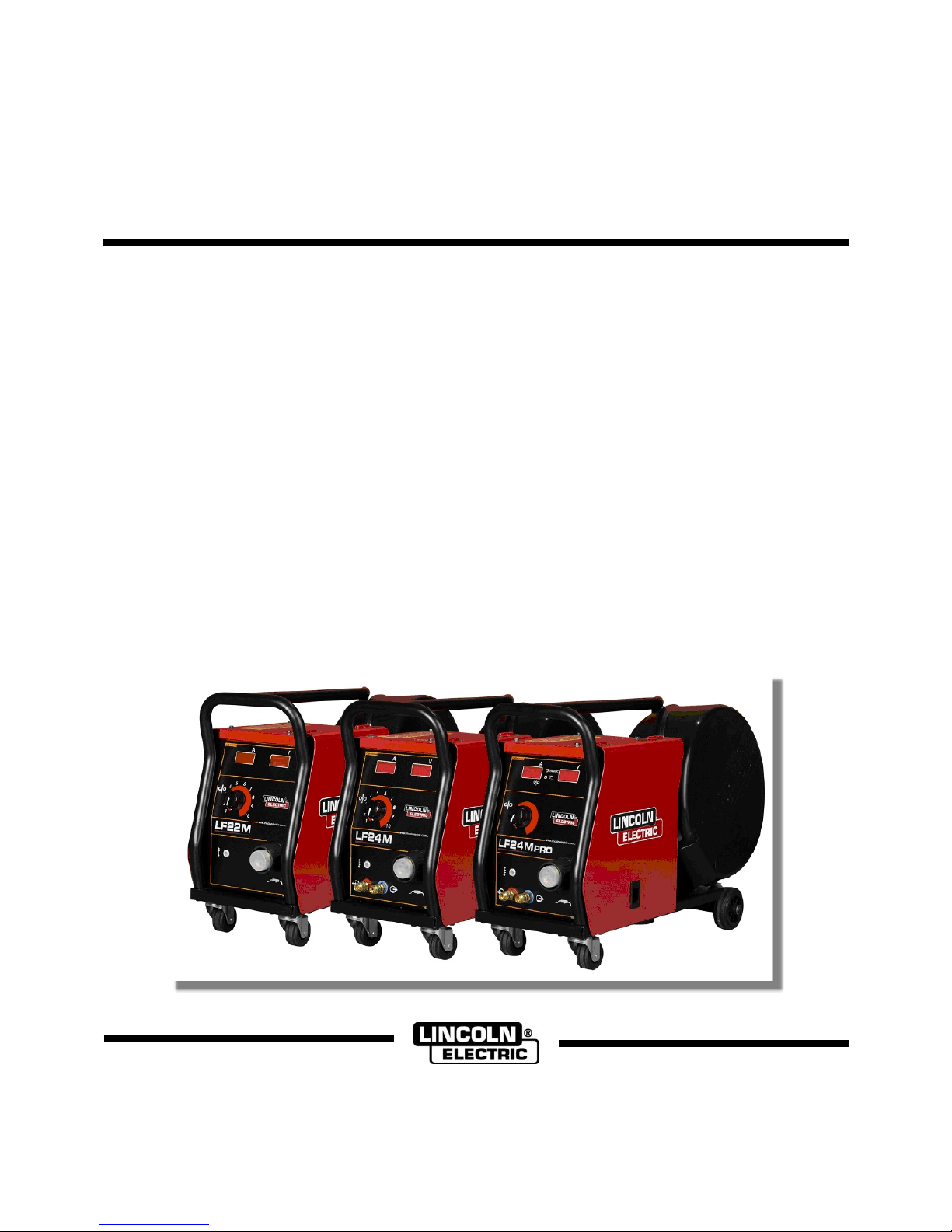
LINC FEED
22M, 24M & 24M PRO
OPERATOR’S MANUAL
MANUALE OPERATIVO
BEDIENUNGSANLEITUNG
MANUAL DE INSTRUCCIONES
MANUEL D'UTILISATION
BRUKSANVISNING OG DELELISTE
GEBRUIKSAANWIJZING
BRUKSANVISNING
INSTRUKCJA OBSŁUGI
KÄYTTÖOHJE
MANUAL DE INSTRUÇÕES
ИНСТРУКЦИЯ ПО ЭКСПЛУАТАЦИИ
LINCOLN ELECTRIC BESTER S.A.
ul. Jana III Sobieskiego 19A, 58-260 Bielawa, Poland
www.lincolnelectric.eu
English EnglishI
Declaration of conformity
LINCOLN ELECTRIC BESTER S.A.
Declares that the welding machine:
LINC FEED 22M
LINC FEED 24M
LINC FEED 24M PRO
conforms to the following directives:
2006/95/CEE, 2004/108/CEE
and has been designed in compliance with the
following standards:
EN 60974-1, EN60974-5, EN 60974-10
(2009)
Paweł Lipiński
Operations Director
LINCOLN ELECTRIC BESTER S.A., ul. Jana III Sobieskiego 19A, 58-260 Bielawa, Poland
12/05
English EnglishII
12/05
THANKS! For having choosen the QUALITY of the Lincoln Electric products.
• Please Examine Package and Equipment for Damage. Claims for material damaged in shipment must be notified
immediately to the dealer.
• For future reference record in the table below your equipment identification information. Model Name, Code &
Serial Number can be found on the machine rating plate.
Model Name:
………………...…………………………….…………………………………………………………………………………………..
Code & Serial number:
………………….……………………………………………….. …………………………………………………….……………..
Date & Where Purchased:
…………………………………………………………………... ……………………….…………………………………………..
ENGLISH INDEX
Safety .............................................................................................................................................................................. 1
Installation and Operator Instructions .............................................................................................................................. 2
Electromagnetic Compatibility (EMC) .............................................................................................................................. 7
Technical Specifications .................................................................................................................................................. 7
WEEE..............................................................................................................................................................................8
Spare Parts...................................................................................................................................................................... 8
Electrical Schematic ........................................................................................................................................................8
Accessories ..................................................................................................................................................................... 8
English English1
Safety
11/04
WARNING
This equipment must be used by qualified personnel. Be sure that all installation, operation, maintenance and repair
procedures are performed only by qualified person. Read and understand this manual before operating this equipment.
Failure to follow the instructions in this manual could cause serious personal injury, loss of life, or damage to this
equipment. Read and understand the following explanations of the warning symbols. Lincoln Electric is not responsible
for damages caused by improper installation, improper care or abnormal operation.
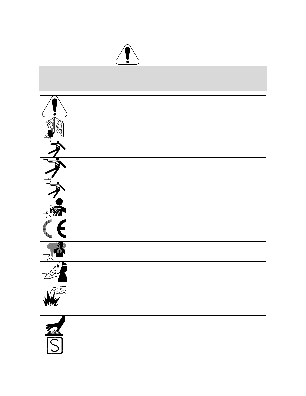
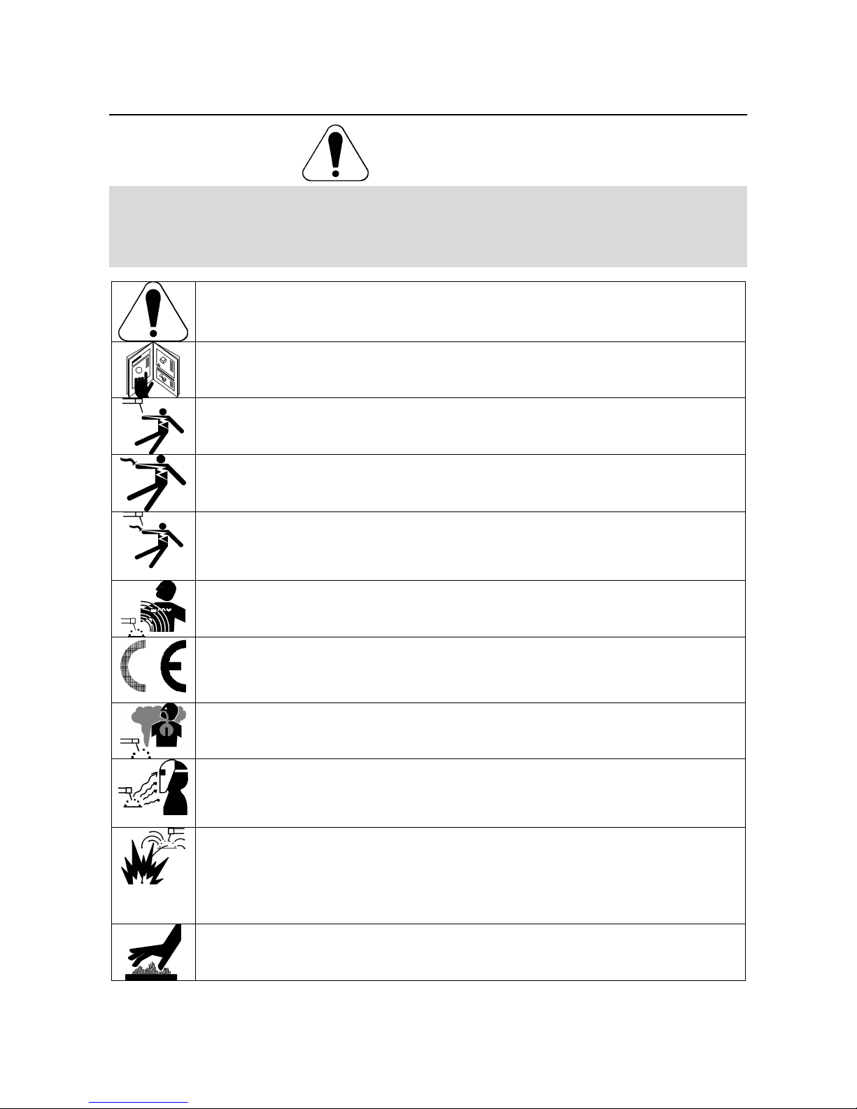
WARNING: This symbol indicates that instructions must be followed to avoid serious personal injury,
loss of life, or damage to this equipment. Protect yourself and others from possible serious injury or
death.
READ AND UNDERSTAND INSTRUCTIONS: Read and understand this manual before operating
this equipment. Arc welding can be hazardous. Failure to follow the instructions in this manual could
cause serious personal injury, loss of life, or damage to this equipment.
ELECTRIC SHOCK CAN KILL: Welding equipment generates high voltages. Do not touch the
electrode, work clamp, or connected work pieces when this equipment is on. Insulate yourself from
the electrode, work clamp, and connected work pieces.
ELECTRICALLY POWERED EQUIPMENT: Turn off input power using the disconnect switch at the
fuse box before working on this equipment. Ground this equipment in accordance with local electrical
regulations.
ELECTRICALLY POWERED EQUIPMENT: Regularly inspect the input, electrode, and work clamp
cables. If any insulation damage exists replace the cable immediately. Do not place the electrode
holder directly on the welding table or any other surface in contact with the work clamp to avoid the
risk of accidental arc ignition.
ELECTRIC AND MAGNETIC FIELDS MAY BE DANGEROUS: Electric current flowing through any
conductor creates electric and magnetic fields (EMF). EMF fields may interfere with some
pacemakers, and welders having a pacemaker shall consult their physician before operating this
equipment.
CE COMPLIANCE: This equipment complies with the European Community Directives.
FUMES AND GASES CAN BE DANGEROUS: Welding may produce fumes and gases hazardous to
health. Avoid breathing these fumes and gases. To avoid these dangers the operator must use
enough ventilation or exhaust to keep fumes and gases away from the breathing zone.
ARC RAYS CAN BURN: Use a shield with the proper filter and cover plates to protect your eyes from
sparks and the rays of the arc when welding or observing. Use suitable clothing made from durable
flame-resistant material to protect you skin and that of your helpers. Protect other nearby personnel
with suitable, non-flammable screening and warn them not to watch the arc nor expose themselves to
the arc.
WELDING SPARKS CAN CAUSE FIRE OR EXPLOSION: Remove fire hazards from the welding
area and have a fire extinguisher readily available. Welding sparks and hot materials from the welding
process can easily go through small cracks and openings to adjacent areas. Do not weld on any
tanks, drums, containers, or material until the proper steps have been taken to insure that no
flammable or toxic vapors will be present. Never operate this equipment when flammable gases,
vapors or liquid combustibles are present.
WELDED MATERIALS CAN BURN: Welding generates a large amount of heat. Hot surfaces and
materials in work area can cause serious burns. Use gloves and pliers when touching or moving
materials in the work area.
SAFETY MARK: This equipment is suitable for supplying power for welding operations carried out in
an environment with increased hazard of electric shock.
English English2
CYLINDER MAY EXPLODE IF DAMAGED: Use only compressed gas cylinders containing the
correct shielding gas for the process used and properly operating regulators designed for the gas and
pressure used. Always keep cylinders in an upright position securely chained to a fixed support. Do
not move or transport gas cylinders with the protection cap removed. Do not allow the electrode,
electrode holder, work clamp or any other electrically live part to touch a gas cylinder. Gas cylinders
must be located away from areas where they may be subjected to physical damage or the welding
process including sparks and heat sources.
Installation and Operator Instructions
Read this entire section before installation or operation
of the machine.
Location and Environment
This machine will operate in harsh environments.
However, it is important that simple preventative
measures are followed to assure long life and reliable
operation:
• Do not place or operate this machine on a surface
with an incline greater than 15° from horizontal.
• Do not use this machine for pipe thawing.
• This machine must be located where there is free
circulation of clean air without restrictions for air
movement to and from the air vents. Do not cover
the machine with paper, cloth or rags when
switched on.
• Dirt and dust that can be drawn into the machine
should be kept to a minimum.
• This machine has a protection rating of IP23. Keep
it dry when possible and do not place it on wet
ground or in puddles.
• Locate the machine away from radio controlled
machinery. Normal operation may adversely affect
the operation of nearby radio controlled machinery,
which may result in injury or equipment damage.
Read the section on electromagnetic compatibility in
this manual.
• Do not operate in areas with an ambient
temperature greater than 40°C.
Duty cycle and Overheating
The duty cycle of a welding machine is the percentage of
time in a 10 minute cycle at which the welder can
operate the machine at rated welding current.
Example: 60% duty cycle:
Welding for 6 minutes. Break for 4 minutes.
Excessive extension of the duty cycle will cause the
thermal protection circuit to activate.
The machine is protected from overheating by a
thermostat. When the machine is overheated the output
of the machine will turn "OFF", and the Thermal Indicator
Light (on front panel of wire feeder) will turn "ON". When
the machine has cooled to a safe temperature the
Thermal Indicator light will go out and the machine may
resume normal operation. Note: For safety reasons the
machine will not come out of thermal shutdown if the
trigger on the welding gun has not been released.
Minutes or decrease
duty cycle
Input Supply Connection
Check the input voltage, phase, and frequency of the
power source that will be connected to this wire feeder.
The allowable input voltage of the power source is
indicated on the rating plate of the wire feeder. Verify
the connection of grounding wires from the power source
to the input source.
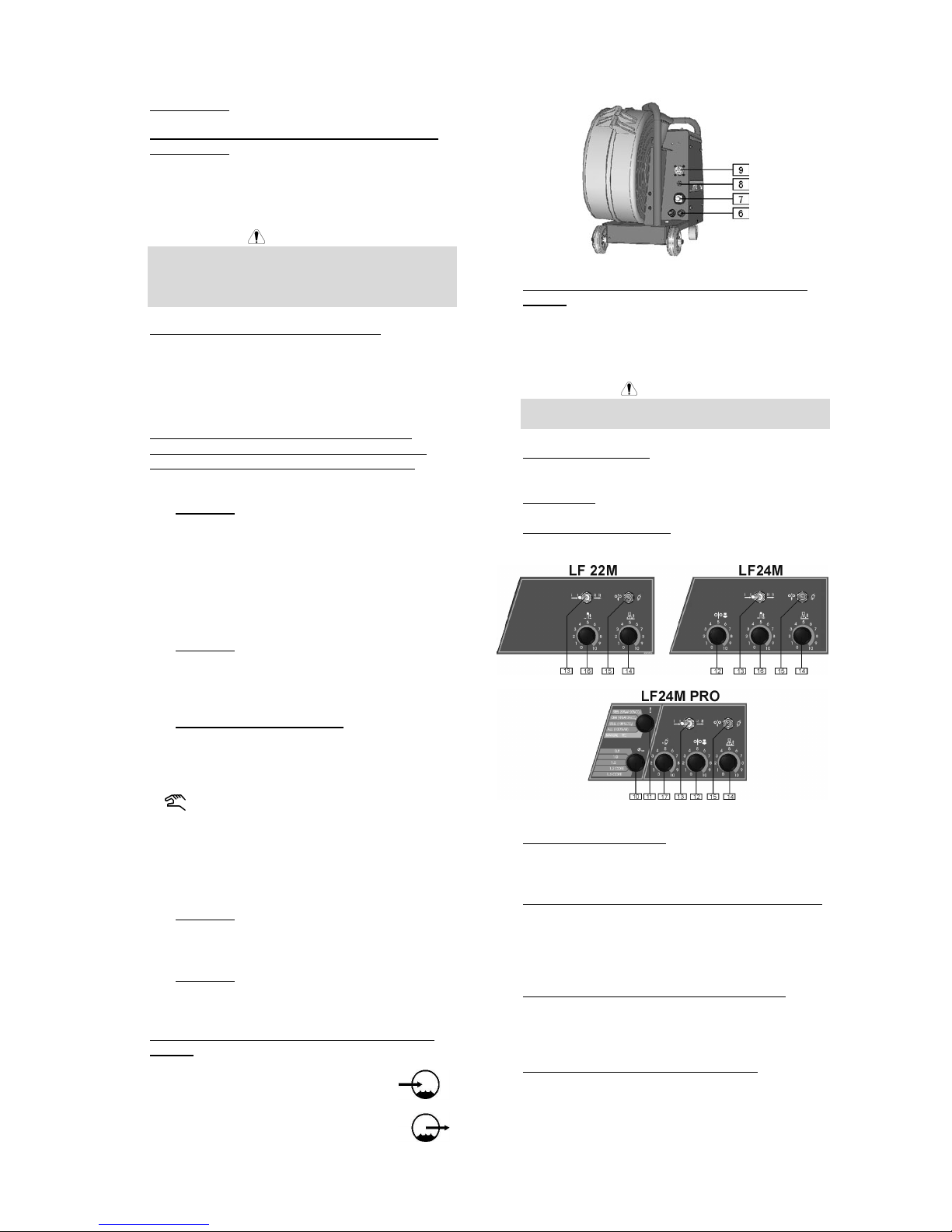
Gas Connection
A gas cylinder must be installed with a proper flow
regulator. Once a gas cylinder with a flow regulator has
been securely installed, connect the gas hose from the
regulator to the machine gas inlet connector. Refer to
point [8] of the images below. The wire feeder supports
all suitable shielding gases including carbon dioxide,
argon and helium at a maximum pressure of 5,0 bar.
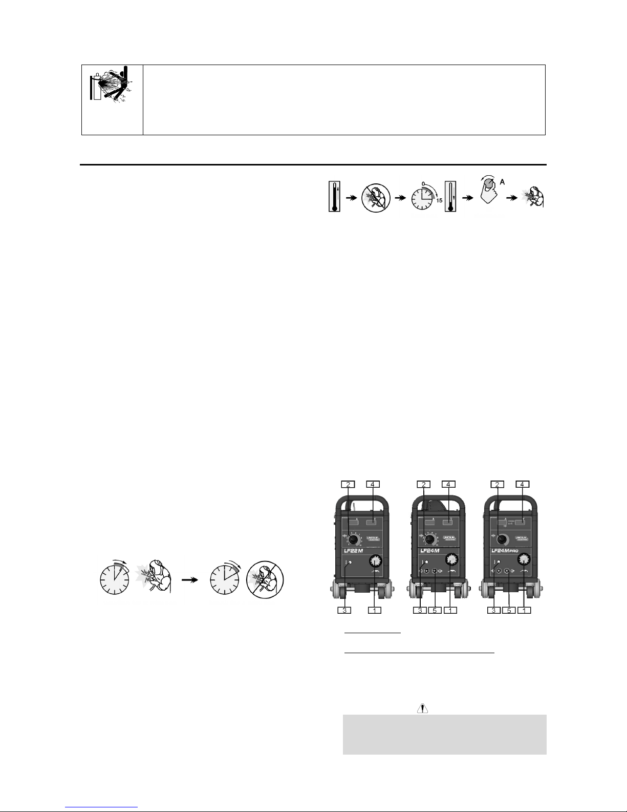
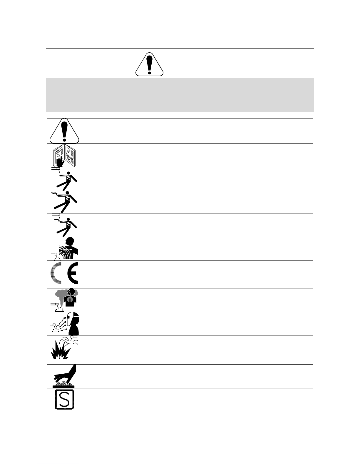
Output Connections
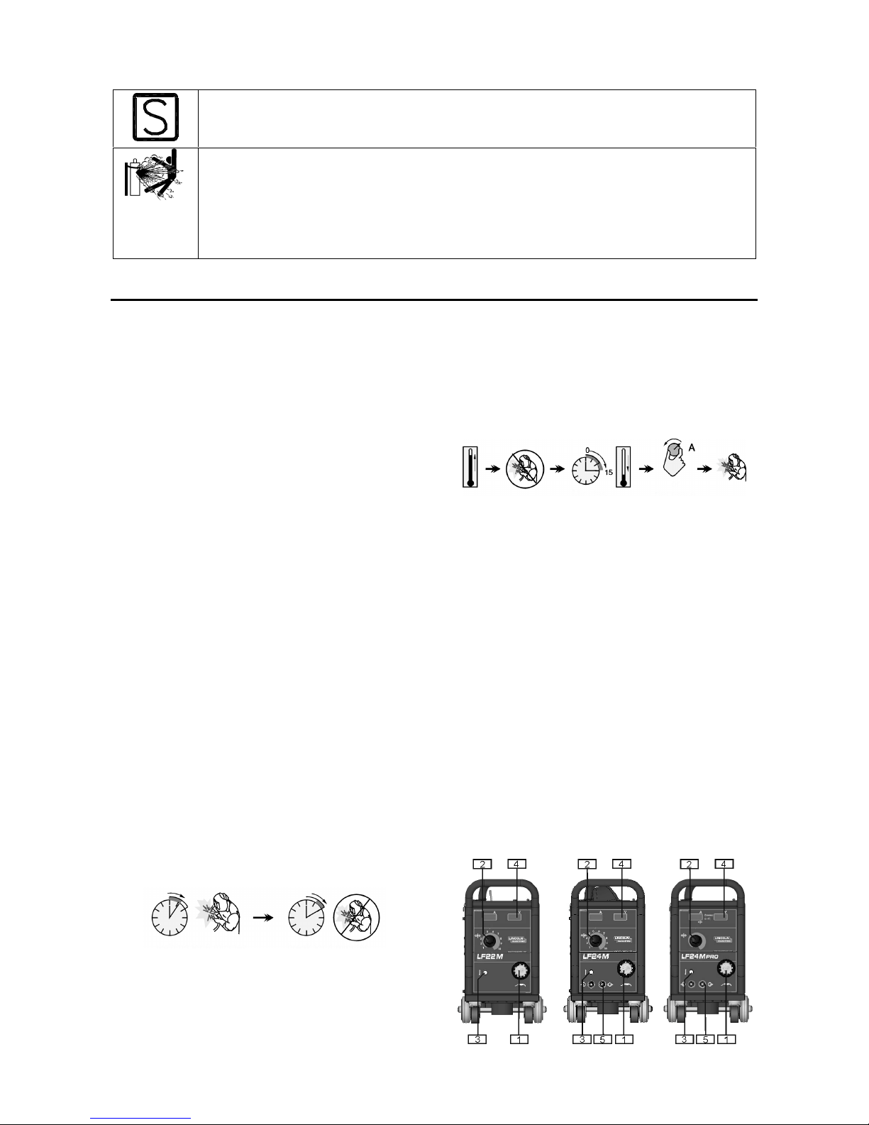
Refer to point [1] of the images below.
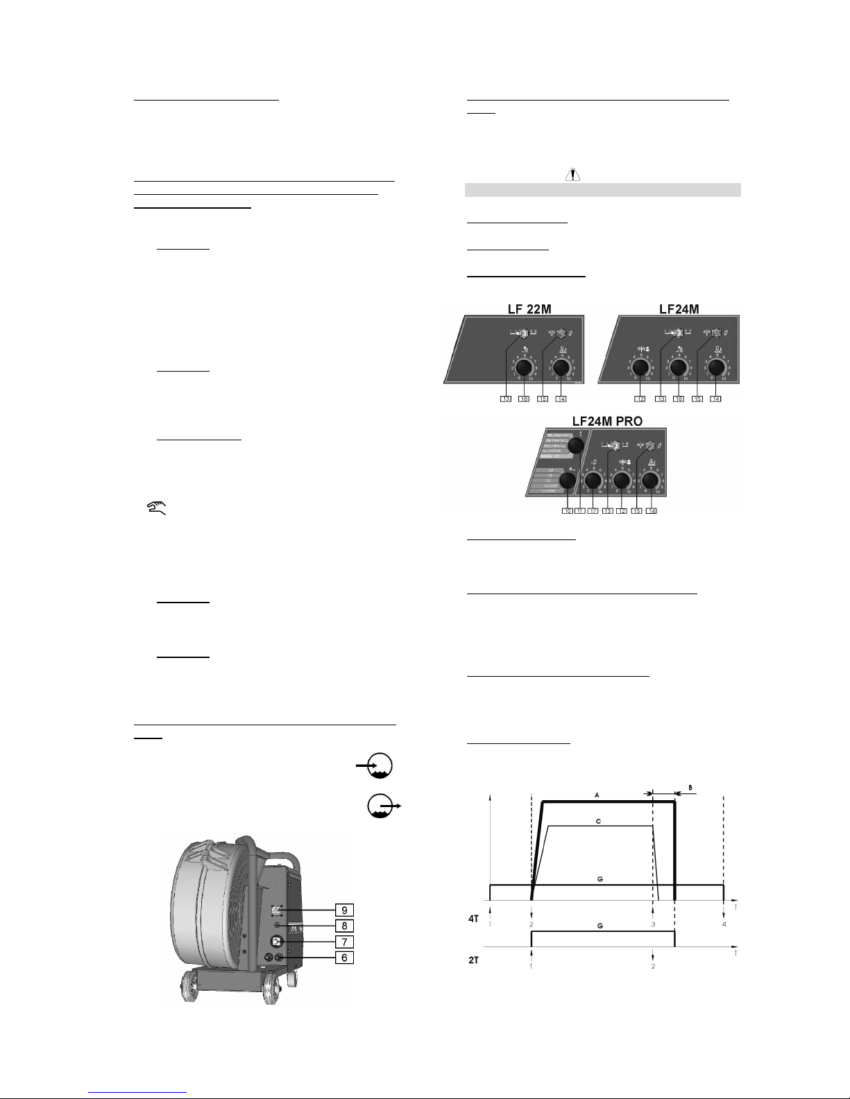
Controls and Operational Features
1. EURO Socket: For connecting welding torch.
2. WFS (Wire Feed Speed) Control Knob: It enables
continuous control of wire feeding speed in the
range from 1.0 to 20m/min with manual mode or
correction of the speed automatically matched by
the machine in the range ±50% at synergic mode.
WARNING
Before welding beginning and during Cold Inch
Switch using the Wire Feed Slow Run Control Knob
[12] has also an influence on the wire feeding
speed.
English English3
3. Thermal Overload Indicator: This lamp will light up
when the machine is overheated and the output has
been turned off. Leave the machine on to allow the
internal components to cool, when the lamp turns off
normal operation is possible.
4. Digital Display Panel (Only on LF24M and LF 24M
PRO. On LF22M is available as an option: see
“accessories” section):
LF24M PRO:
• Display A: It shows the actual welding current
value (in A), and after finishing welding
process, it shows the average value of the
welding current. When the WFS value is
changed [2], the display shows the value of
adjusted WFS (in m/min) - for manual mode or
correction of the speed automatically matched
by the machine, in the range 0.75-1.25 at
synergic mode.
• Display V: It shows the actual value of welding
voltage (in V), and after finishing welding
process, it shows the average value of welding
voltage. When the WFS value is changed [2],
the display is blank.
• Work Indicators: These lamps shows the work
mode of the machine:
SYNERGIC
When lit, the machine works in
Synergic mode (automatic mode).
When lit, the machine works in Manual
mode.
Select the desired work with the "Welding Material
and Gas Mix Choice Knob" [11].
LF24M:
• Display A: It shows the actual welding current
value (in A), and after finishing welding
process, it shows the average value of the
welding current.
• Display V: It shows the actual value of welding
voltage (in V), and after finishing welding
process, it shows the average value of welding
voltage.
5. Quick Connect Couplings (For water cooled model
only): For connecting water cooled torches.
Warm water from torch.
Cool water to torch.
6. Quick Connect Couplings (For water cooled model
only): If water cooled torches are used, connect
water lines from water cooler here. Refer to torch
and water cooler guidelines for recommended
cooling liquid and flow rates.
WARNING
Max cooling liquid pressure is 4 Bar.
7. Fast-Mate Adapter: Input power connection.
8. Gas Connector: Connection for gas line.
9. Amphenol Connection: 8-Pin connection to power
source.
10. Wire Diameter Knob: It allows the choice of the wire
diameter requested for the desired welding process.
This feature is available only for the synergic mode.
11. Welding Material and Gas Mix Choice Knob: This
knob enables the choice of:
• The welded material and its appropriate gas
mixture.
• The manual / synergic work mode.
12. Wire Feed Slow Run Control Knob: It enables
control of wire feeding speed before welding
beginning, in the range from 0.1 to1.0 of the value
set by the "Wire Feed Speed Control Knob" [2].
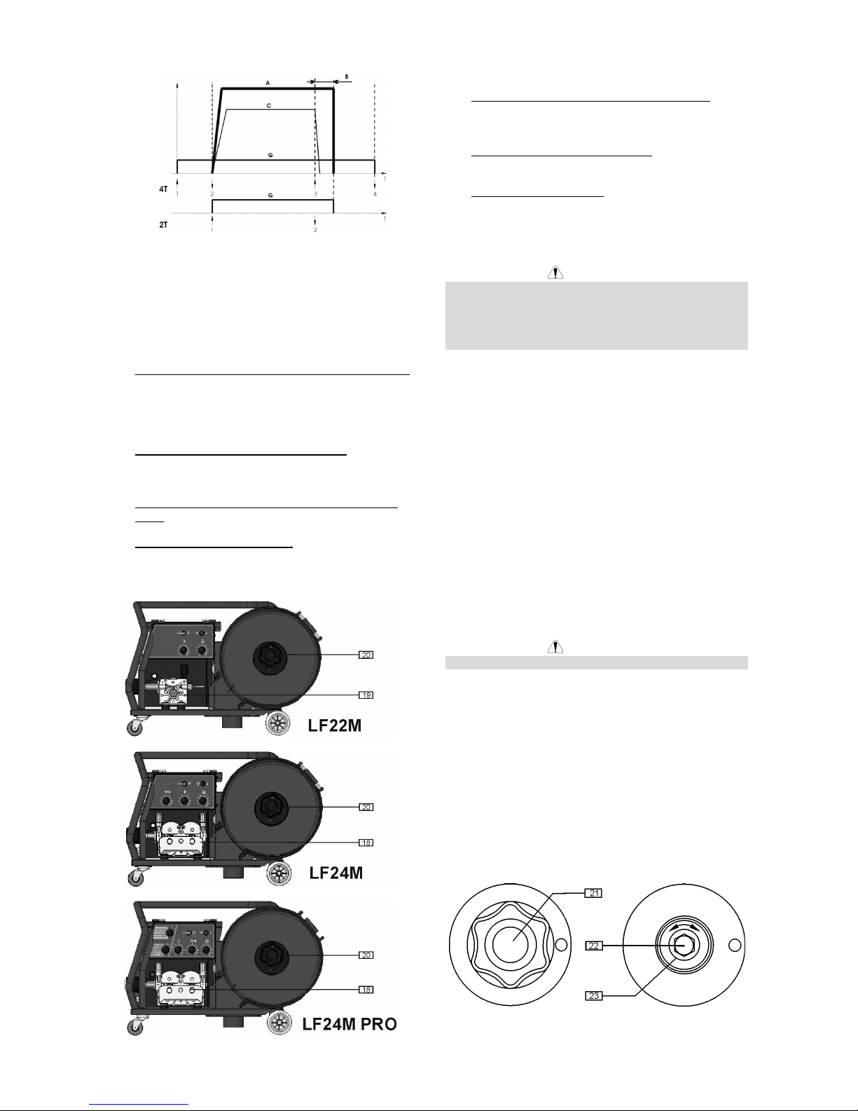
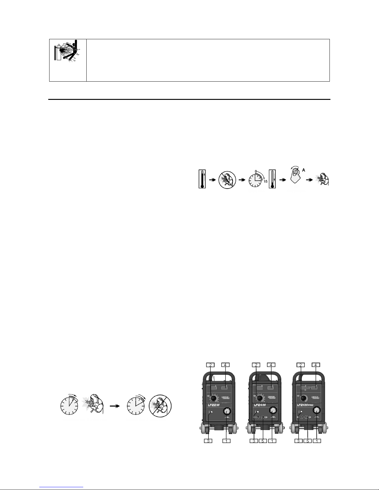
13. Torch Mode Switch: It enables selection of 2-step
or 4-step torch mode. The functionality of 2T/4T
mode is shown in the picture below:
↑
Trigger pressed
↓
Trigger released
English English4
A. Welding Current.
B. Burnback time.
C. WFS.
G. Gas.
14. Burnback Time Control Knob: It enables to obtain
the desired length of electrode wire, which protrudes
from the tip of the torch after ending welding;
adjusting range from 8 to 250ms.
15. Cold Inch / Gas Purge Switch: This switch enables
wire feeding or gas flow without turning on output
voltage.
16. Spot Welding Time Control Knob: It enables time
control in the range from 0.2 to 10 s.
17. Gas Preflow (only LF 24M PRO): It determine
period of time between start of gas and start of
current flow, from 0,01 to 1s.
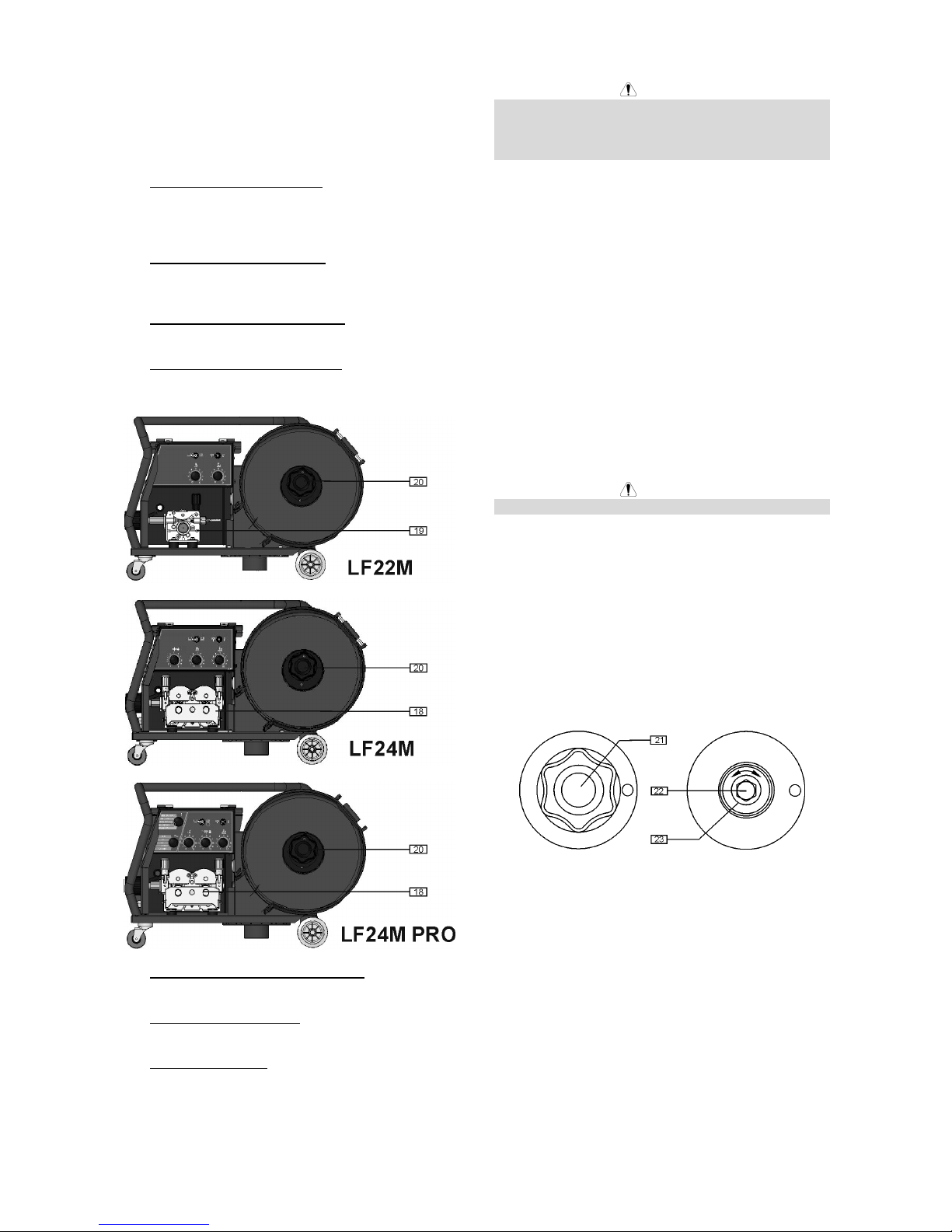
18. Wire Drive (only LF 24M, 24M PRO): 4-Roll wire
drive compatible with 37mm drive rolls.
19. Wire Drive (only LF 22M): 2-Roll wire drive
compatible with 37mm drive rolls.
20. Wire Spool Support: Maximum 15kg spools.
Accepts plastic, steel and fiber spools onto 51mm
spindle. Also accepts Readi-Reel
®
type spools onto
included spindle adapter.
WARNING
The Linc Feed wire feeders must be used with the door
completely closed during welding.
Not use handle to move the Linc Feed during work.
Loading the Electrode Wire
Open the side cover of the machine.
Unscrew the fastening cap of the sleeve.
Load the spool with the wire on the sleeve such that the
spool turns clockwise when the wire is fed into the wire
feeder.
Make sure that the spool locating pin goes into the fitting
hole on the spool.
Screw in the fastening cap of the sleeve.
Put on the wire roll using the correct groove
corresponding to the wire diameter.
Free the end of the wire and cut off the bent end making
sure it has no burr.
WARNING
Sharp end of the wire can hurt.
Rotate the wire spool clockwise and thread the end of
the wire into the wire feeder as far as the Euro socket.
Adjust force of pressure roll of the wire feeder properly.
Adjustments of Brake Torque of Sleeve
To avoid spontaneous unrolling of the welding wire the
sleeve is fitted with a brake.
Adjustment is carried by rotation of its screw M10, which
is placed inside of the sleeve frame after unscrewing the
fastening cap of the sleeve.
21. Fastening cap.
22. Adjusting screw M10.
23. Pressing spring.
Turning the screw M10 clockwise increases the spring
tension and you can increase the brake torque.
Turning the screw M10 counterclockwise decreases the
spring tension and you can decrease the brake torque.
After finishing of adjustment, you should screw in the
fastening cap again.
Adjusting of Force of Pressure Roll
Force
Pressure force is adjusted by turning the adjustment nut
clockwise to increase force, counterclockwise to
decrease force.

English English5
WARNING
If the roll pressure is too low the roll will slide on the wire.
If the roll pressure is set too high the wire may be
deformed, which will cause feeding problems in the
welding gun. The pressure force should be set properly.
Decrease the pressure force slowly until the wire just
begins to slide on the drive roll and then increase the
force slightly by turning of the adjustment nut by one
turn.
Inserting Electrode Wire into Welding
Torch
Connect the proper welding torch to the Euro socket, the
rated parameters of the torch and of the welding source
shall match.
Remove the gas diffuser and contact tip from the
welding torch.
Set the wire feeding speed in the position of about
10m/min by the WFS knob [2].
Switch the Cold Inch / Gas Purge switch [15] in the
position "Cold Inch" and keep in this position until the
electrode wire leaves the contact tip of the welding torch.
WARNING
Take precaution to keep eyes and hands away from the
end of the torch while feeding wire.
WARNING
Once the wire has finished feeding through the welding
gun turn the wire supply off before replacing to contact
tip and gas diffuser.
Welding with MIG / MAG method in
Manual mode
To begin welding process with MIG/MAG method in
manual mode you should:
• Switch ON the machine which supplies the wire
feeder.
• Insert the electrode wire into the torch using "Cold
Inch" switch [15].
• Check gas flow with "Gas Purge" switch [15].
• Set knob [11] (only LF 24M PRO) in Manual position
(verify that the panel [4] has lit the Manual mode).
• According to selected welding mode and material
thickness set the proper welding voltage and the
wire feeding speed with WFS knob [2].
• Obeying the appropriate rules, you can begin to
weld.
Welding Source Select (only LF 24M
PRO)
The wire feeder LF 24M PRO can work with below
power sources in synergic mode:
• Powertec 305S.
• Powertec 365S.
• Powertec 425S.
• Powertec 505S.
The feeder is set for co-operation with Powertec 425S
(factory default).
If it is necessary to change the power source, you
should:
• Switch the supply of the wire feeder off.
• Set the knob of the choice wire diameter selection
[10] in "1.6 CORE" position. Set the knob of the
choice welded material and gas mixture [11] in
"MANUAL" position.
• Switch the supply of the wire feeder on.
• Within 15s switch the knob of the choice wire
diameter selection [10] in "0.8" position and the
knob of the choice welded material and gas mixture
[11] in "STEEL (80%AR 20%CO
2
)" position (verify
that the display "V" has lit "S").
• Use the knob [2] to set the proper welding source on
display:
• 305 S
• 365 S
• 425 S
• 505 S
• Save the selected value through switch the knob of
the choice wire diameter selection [10] in "1.6
CORE" position – the wire feeder is ready to work.
WARNING
The display "V" lights the selected source number
(305S/365S/425S/505S) for 2 seconds after the supply
of the wire feeder is switched on.
Welding with MIG / MAG method in
Synergic mode (only LF 24M PRO)
To begin welding process with MIG/MAG method in
synergic mode you should:
• Switch ON the machine which supplies the wire
feeder.
• Insert the electrode wire into the torch using "Cold
Inch" switch [15].
• Check gas flow with "Gas Purge" switch [15].
• Set the knob of the choice wire diameter selection
[10] in the position corresponding to the diameter of
the used wire.
• Set the knob of the choice welded material and gas
mixture [11] in the position corresponding to the
used material.
WARNING
If the selected welding process does not have
synergic mode, three horizontal dashes will appear
on the display "A".
• According to the selected welding mode and
material thickness, set the proper welding voltage
on the welding source.
WARNING
For synergic welding mode the machine
automatically selects the proper wire feeding speed
for each position of the welding source. The
automatic speed value can be adjusted in the range
of the ±50% by the WFS Control Knob [2].
• Obeying the appropriate rules, you can begin to
weld.
Water Cooler Control (only LF 24M
PRO)
The LF 24M PRO wire feeder allows the water cooler to
the automatic work with Powertec 365S/425S/505S, i.e.:
• When a weld is started, the Cooler is automatically
English English6
switched on.
• When the weld is stopped, the Cooler continues to
run for about 5min., after this time, it is automatically
switched off.
• If the weld is restarted in a time lower than 5min.,
the Cooler continues to run.
The wire feeder has the possibility to switch the
automatic work of the water cooler off and set it in
continuously work. If it is necessary to change the water
cooler kind of work, you should:
• Switch off the machine which supplies the wire
feeder.
• Set the knob of the choice wire diameter selection
[10] in "1.0" position. Set the knob of the choice
welded material and gas mixture [11] in "CRNI
(98%AR 2%CO
2
)" position.
• Switch the supply of the wire feeder on.
• Within 15s switch the knob of the choice wire
diameter selection [10] in "1.2" position and the
knob of the choice welded material and gas mixture
[11] in "STEEL (100%CO2)" position – the water
cooler has been switched on and the display "V"
has lit "on".
If it is necessary to return the automatic work of the
water cooler you should do the foregoing actions again
(the display “V” has lit " 5'' ").
WARNING
The display "V" lights information about work mode of
the water cooler (5"/on) for 2 seconds after the supply of
the wire feeder is switched on.
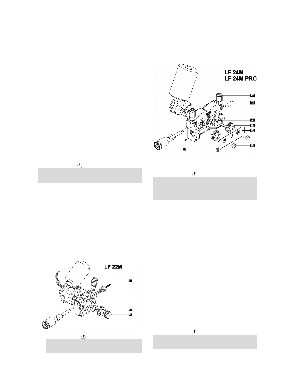
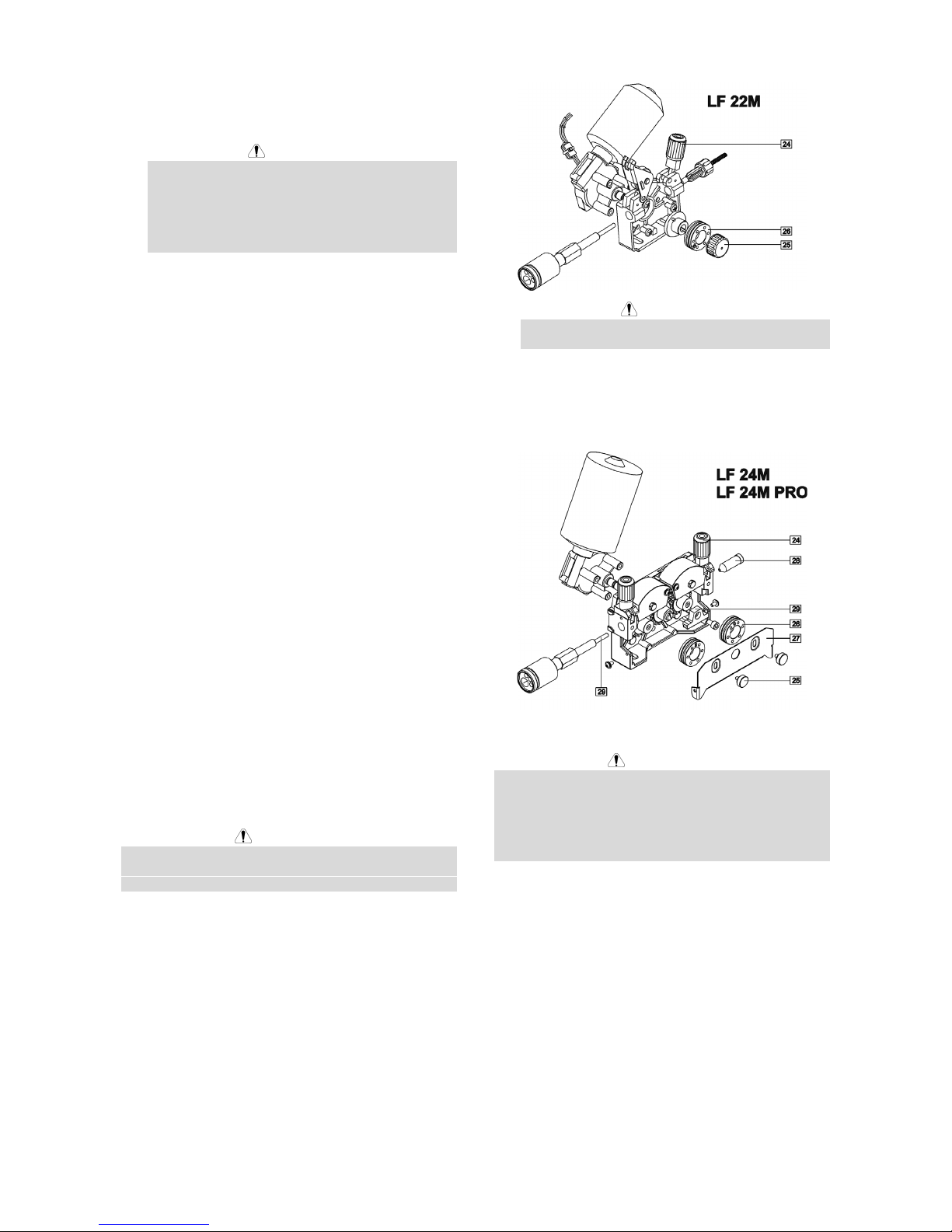
Changing Driving Rolls
The wire feeder is equipped with drive rolls for the wire
of 1.0 and 1.2mm (for LF 24M/24M PRO) or 0.8 and
1.0mm (for LF 22M). For others wire sizes, is available
the proper drive rolls kit (see chapter Accessories for
ordering the desired kit). Below the drive rolls
replacement procedure:
• Switch off the machine which supplies the wire
feeder.
• Release the pressure roll lever [24].
• Unscrew the fastening cap [25].
• Open the protection cover [27].
• Change the drive rolls [26] with the compatible ones
corresponding to the used wire.
WARNING
For wires with the diameter greater than 1.6mm
(only for LF 24M/24M PRO), the following parts are
to be changed:
• The guide tube of the feeding console [28] and
[29].
• The guide tube of the Euro socket [30].
• Replace and tighten the protection cover [27] to the
drive rolls.
• Screw the protection cover by fastening screws [25].
Maintenance
WARNING
For any maintenance or repair operations it is
recommended to contact the nearest Technical Service
Center or Lincoln Electric. Maintenance or repairs
performed by unauthorized service centers or personnel
will null and void the manufacturer's warranty.
The frequency of the maintenance operations may vary
in accordance with the working environment where the
machine is placed.
Any noticeable damage should be reported immediately.
Routine maintenance
• Check condition of insulation and connections of the
work cables and input power supply cable.
• Remove the spatters from the welding gun nozzle.
Spatters could interfere with the shielding gas flow
to the arc.
• Check the welding gun condition: replace it, if
necessary.
• Check condition and operation of the cooling fan.
Keep clean its airflow slots.
Periodic maintenance
Perform the routine maintenance and, in addition:
• Keep the machine clean. Using a dry (and low
pressure) airflow, remove the dust from the external
case and from the cabinet inside.
• Check condition of all connections and change if
necessary.
• Check and tighten all screws.
WARNING
Mains supply network must be disconnected from the
machine before each maintenance and service. After
each repair, perform proper tests to ensure safety.
English English7
Electromagnetic Compatibility (EMC)
11/04
This machine has been designed in accordance with all relevant directives and standards. However, it may still generate
electromagnetic disturbances that can affect other systems like telecommunications (telephone, radio, and television) or
other safety systems. These disturbances can cause safety problems in the affected systems. Read and understand
this section to eliminate or reduce the amount of electromagnetic disturbance generated by this machine.
This machine has been designed to operate in an industrial area. To operate in a domestic area it is
necessary to observe particular precautions to eliminate possible electromagnetic disturbances. The
operator must install and operate this equipment as described in this manual. If any electromagnetic
disturbances are detected the operator must put in place corrective actions to eliminate these disturbances
with, if necessary, assistance from Lincoln Electric.
Before installing the machine, the operator must check the work area for any devices that may malfunction because of
electromagnetic disturbances. Consider the following.
• Input and output cables, control cables, and telephone cables that are in or adjacent to the work area and the
machine.
• Radio and/or television transmitters and receivers. Computers or computer controlled equipment.
• Safety and control equipment for industrial processes. Equipment for calibration and measurement.
• Personal medical devices like pacemakers and hearing aids.
• Check the electromagnetic immunity for equipment operating in or near the work area. The operator must be sure
that all equipment in the area is compatible. This may require additional protection measures.
• The dimensions of the work area to consider will depend on the construction of the area and other activities that are
taking place.
Consider the following guidelines to reduce electromagnetic emissions from the machine.
• Connect the machine to the input supply according to this manual. If disturbances occur if may be necessary to take
additional precautions such as filtering the input supply.
• The output cables should be kept as short as possible and should be positioned together. If possible connect the
work piece to ground in order to reduce the electromagnetic emissions. The operator must check that connecting
the work piece to ground does not cause problems or unsafe operating conditions for personnel and equipment.
• Shielding of cables in the work area can reduce electromagnetic emissions. This may be necessary for special
applications.
Technical Specifications
LINC FEED 22M 24M & 24M PRO:
INPUT VOLTAGE WIRE FEED SPEED
34-44 Vac 1.0-20 m/min
RATED OUTPUT AT 40°C
Duty Cycle
(based on a 10 min. period)
100%
60%
Output Current
385 A
500 A
OUTPUT RANGE
Welding Current Range
20-500 A
Maximum Open Circuit Voltage
113 Vdc or Vac peak
WIRE SIZES (mm)
Solid wires Cored wires Aluminium wires
LF 22M
0.6 to 1.2
LF 22M
1.2
LF 22M
1.0 to 1.2
LF 24M, 24M PRO
0.6 to 1.6
LF 24M, 24M PRO
1.2 to 2.4
LF 24M, 24M PRO
1.0 to 1.6
PHYSICAL DIMENSIONS
Weight
LF 22M
15 Kg
Height
440 mm
Width
270 mm
Length
636 mm
LF 24M, 24M PRO
17 Kg
Operating Temperature
–10°C to +40°C
Storage Temperature
-25°C to +55°C
English English8
WEEE
07/06
English
Do not dispose of electrical equipment together with normal waste!
In observance of European Directive 2002/96/EC on Waste Electrical and Electronic Equipment (WEEE)
and its implementation in accordance with national law, electrical equipment that has reached the end of its
life must be collected separately and returned to an environmentally compatible recycling facility. As the
owner of the equipment, you should get information on approved collection systems from our local
representative.
By applying this European Directive you will protect the environment and human health!
Spare Parts
12/05
Part List reading instructions
• Do not use this part list for a machine if its code number is not listed. Contact the Lincoln Electric Service
Department for any code number not listed.
• Use the illustration of assembly page and the table below to determine where the part is located for your particular
code machine.
• Use only the parts marked "X" in the column under the heading number called for in the assembly page (# indicate
a change in this printing).
First, read the Part List reading instructions above, then refer to the "Spare Part" manual supplied with the machine, that
contains a picture-descriptive part number cross-reference.
Electrical Schematic
Refer to the "Spare Part" manual supplied with the machine.
Accessories
K10347-PG-xxM Source/wire feeder cable (gas). Available in 5, 10 or 15m.
K10347-PGW-xxM Source/wire feeder cable (gas and water). Available in 5, 10 or 15m.
K10158 Plastic adaptor for 15-kg coils.
K14032-1 Heavy duty undercarriage wheels kit.
K14073-1 AV Meter Kit (LF 22M only).
LF 22M: Drive rolls and guide tubes 2 driven rolls
KP14016-0.8
KP14016-1.0
KP14016-1.2
Solid wires:
0,6-0,8mm
0,8-1,0mm
1,0-1,2mm
KP14016-1.6R
Cored wires:
1.2-1.6mm
KP14016-1.2A
Aluminum wires:
1,0-1,2mm
LF 24M, 24M PRO: Drive rolls and guide tubes 4 driven rolls
KP14017-0.8
KP14017-1.0
KP14017-1.2
KP14017-1.6
Solid wires:
0,6-0,8mm
0,8-1,0mm
1,0-1,2mm
1,2-1,6mm
KP14017-1.6R
KP14017-2.4R
Cored wires:
1.2-1.6mm
1.6-2.4mm
KP14017-1.2A
KP14017-1.6A
Aluminum wires:
1,0-1,2mm
1,2-1,6mm

Italiano ItalianoI
Dichiarazione di conformità
LINCOLN ELECTRIC BESTER S.A.
Dichiara che il generatore per saldatura tipo:
LINC FEED 22M
LINC FEED 24M
LINC FEED 24M PRO
è conforme alle seguenti direttive:
2006/95/CEE, 2004/108/CEE
ed è stato progettato in conformità alle seguenti
norme:
EN 60974-1, EN60974-5, EN 60974-10
(2009)
Paweł Lipiński
Operations Director
LINCOLN ELECTRIC BESTER S.A., ul. Jana III Sobieskiego 19A, 58-260 Bielawa, Poland
12/05

Italiano ItalianoII
12/05
GRAZIE! Per aver scelto la QUALITÀ dei prodotti Lincoln Electric.
• Esamini Imballo ed Equipaggiamento per rilevare eventuali danneggiamenti. Le richieste per materiali danneggiati
dal trasporto devono essere immediatamente notificate al rivenditore.
• Per ogni futuro riferimento, compilare la tabella sottostante con le informazioni di identificazione equipaggiamento.
Modello, Codice (Code) e Matricola (Serial Number) sono reperibili sulla targa dati della macchina.
Modello:
………………...…………………………….…………………………………………………………………………………………..
Code (codice) e Matricola:
………………….……………………………………………….. …………………………………………………….……………..
Data e Luogo d’acquisto:
…………………………………………………………………... ……………………….…………………………………………..
INDICE ITALIANO
Sicurezza......................................................................................................................................................................... 1
Installazione e Istruzioni Operative..................................................................................................................................2
Compatibilità Elettromagnetica (EMC)............................................................................................................................. 7
Specifiche Tecniche......................................................................................................................................................... 7
RAEE (WEEE)................................................................................................................................................................. 8
Parti di Ricambio .............................................................................................................................................................8
Schema Elettrico .............................................................................................................................................................8
Accessori.........................................................................................................................................................................8
Italiano Italiano1
Sicurezza
11/04
AVVERTENZA
Questa macchina deve essere impiegata solo da personale qualificato. Assicuratevi che tutte le procedure di
installazione, impiego, manutenzione e riparazione vengano eseguite solamente da persone qualificate. Leggere e
comprendere questo manuale prima di mettere in funzione la macchina. La mancata osservanza delle istruzioni di
questo manuale può provocare seri infortuni, anche mortali, alle persone, o danni alla macchina. Leggere e
comprendere le spiegazioni seguenti sui simboli di avvertenza. La Lincoln Electric non si assume alcuna responsabilità
per danni conseguenti a installazione non corretta, incuria o impiego in modo anormale.
AVVERTENZA: Questo simbolo indica che occorre seguire le istruzioni per evitare seri infortuni,
anche mortali, alle persone o danni a questa macchina. Proteggete voi stessi e gli altri dalla
possibilità di seri infortuni anche mortali.
LEGGERE E COMPRENDERE LE ISTRUZIONI: Leggere e comprendere questo manuale prima di
far funzionare la macchina. La saldatura ad arco può presentare dei rischi. La mancata osservanza
delle istruzioni di questo manuale può provocare seri infortuni, anche mortali, alle persone o danni alla
macchina.
LA FOLGORAZIONE ELETTRICA E’ MORTALE: Le macchine per saldatura generano tensioni
elevate. Non toccate l’elettrodo, il morsetto di massa o pezzi da saldare collegati alla macchina
quando la macchina è accesa. Mantenetevi isolati elettricamente da elettrodo, morsetto e pezzi
collegati a questo.
MACCHINA CON ALIMENTAZIONE ELETTRICA: Togliere l’alimentazione con l’interruttore ai fusibili
prima di svolgere operazioni su questa macchina. Mettere la macchina a terra secondo le normative
vigenti.
MACCHINA CON ALIMENTAZIONE ELETTRICA: Ispezionare periodicamente i cavi di
alimentazione, all’elettrodo e al pezzo. Se si riscontrano danni all’isolamento sostituire
immediatamente il cavo. Non posare la pinza portaelettrodo direttamente sul banco di saldatura o
qualsiasi altra superficie in contatto con il morsetto di massa per evitare un innesco involontario
dell’arco.
I CAMPI ELETTRICI E MAGNETICI POSSONO ESSERE PERICOLOSI: Il passaggio di corrente
elettrica in un conduttore produce campi elettromagnetici. Questi campi possono interferire con alcuni
cardiostimolatori (“pacemaker”) e i saldatori con un cardiostimolatore devono consultare il loro medico
su possibili rischi prima di impiegare questa macchina.
CONFORMITÀ CE: Questa macchina è conforme alle Direttive Europee.
FUMI E GAS POSSONO ESSERE PERICOLOSI: La saldatura può produrre fumi e gas dannosi alla
salute. Evitate di respirare questi fumi e gas. Per evitare il pericolo l’operatore deve disporre di una
ventilazione o di un'estrazione di fumi e gas che li allontanino dalla zona in cui respira.
I RAGGI EMESSI DALL’ARCO BRUCIANO: Usate una maschera con schermatura adatta a
proteggervi gli occhi da spruzzi e raggi emessi dall’arco mentre saldate o osservate la saldatura.
Indossare indumenti adatti in materiale resistente alla fiamma per proteggere il corpo, sia vostro che
dei vostri aiutanti. Le persone che si trovano nelle vicinanze devono essere protette da schermature
adatte, non infiammabili, e devono essere avvertite di non guardare l’arco e di non esporvisi.
GLI SPRUZZI DI SALDATURA POSSONO PROVOCARE INCENDI O ESPLOSIONI: Allontanare
dall'area di saldatura quanto può prendere fuoco e tenere a portata di mano un estintore. Gli spruzzi
o altri materiali ad alta temperatura prodotti dalla saldatura attraversano con facilità eventuali piccole
aperture raggiungendo le zone vicine. Non saldare su serbatoi, bidoni, contenitori o altri materiali fino
a che non si sia fatto tutto il necessario per assicurarsi dell'assenza di vapori infiammabili o nocivi.
Non impiegare mai questa macchina se vi è presenza di gas e/o vapori infiammabili o combustibili
liquidi.
I MATERIALI SALDATI BRUCIANO: Il processo di saldatura produce moltissimo calore. Ci si può
bruciare in modo grave con le superfici e materiali caldi della zona di saldatura. Impiegare guanti e
pinze per toccare o muovere materiali nella zona di saldatura.
Italiano Italiano2
MARCHIO DI SICUREZZA: Questa macchina è adatta a fornire energia per operazioni di saldatura
svolte in ambienti con alto rischio di folgorazione elettrica.
LE BOMBOLE POSSONO ESPLODERE SE SONO DANNEGGIATE: Impiegate solo bombole
contenenti il gas compresso adatto al processo di saldatura utilizzato e regolatori di flusso, funzionanti
regolarmente, progettati per il tipo di gas e la pressione in uso. Le bombole vanno tenute sempre in
posizione verticale e assicurate con catena ad un sostegno fisso. Non spostate le bombole senza il
loro cappello di protezione. Evitate qualsiasi contatto dell’elettrodo, della sua pinza, del morsetto di
massa o di ogni altra parte in tensione con la bombola del gas. Le bombole gas vanno collocate
lontane dalle zone dove possano restare danneggiate dal processo di saldatura con relativi spruzzi e
da fonti di calore.
Installazione e Istruzioni Operative
Leggere tutta questa sezione prima di installare e
impiegare la macchina.
Collocazione e ambiente
Questa macchina è in grado di funzionare in ambienti
difficili. E’ comunque importante seguire delle semplici
misure di prevenzione per garantirne una lunga durata e
un funzionamento affidabile.
• Non collocare o impiegare la macchina su superfici
inclinate più di 15° rispetto all’orizzontale.
• Non usare questa macchina per sgelare tubi.
• La macchina va collocata ove vi sia una circolazione
di aria pulita senza impedimenti al suo movimento in
entrata e uscita dalle feritoie. Non coprire la
macchina con fogli di carta, panni o stracci quando
è accesa.
• Tenere al minimo polvere e sporco che possano
entrare nella macchina.
• Questa macchina ha una protezione di grado IP23.
Tenetela più asciutta possibile e non posatela su
suolo bagnato o dentro pozzanghere.
• Disponete la macchina lontana da macchinari
controllati via radio. Il suo funzionamento normale
può interferire negativamente sul funzionamento di
macchine controllate via radio poste nelle vicinanze,
con conseguenze di infortuni o danni materiali.
Leggete la sezione sulla compatibilità
elettromagnetica di questo manuale.
• Non impiegate la macchina in zone ove la
temperatura ambiente supera i 40°C.
Fattore di Intermittenza e
Surriscaldamento
Il fattore di intermittenza di una saldatrice è la
percentuale di tempo su un periodo di 10 minuti durante
la quale si può far funzionare la macchina alla corrente
nominale corrispondente.
Esempio: Fattore di intermittenza 60%:
Saldatura per 6 minuti. Interruzione per 4 minuti.
Il superamento del fattore di intermittenza provoca
l’attivazione del circuito di protezione termica.
La macchina è protetta con un termostato dai
surriscaldamenti. Quando la macchina si surriscalda la
sua uscita viene interrotta, e la spia indicatrice di
sovraccarico termico (sul pannello frontale del trainafilo)
si accende. Quando la macchina si è raffreddata ad una
temperatura di sicurezza la spia di sovraccarico termico
si spegne e la macchina può riprendere il funzionamento
normale. Nota: Per motivi di sicurezza la macchina non
esce dalla condizione di arresto per sovraccarico termico
se il pulsante torcia non è stato rilasciato.
Minuti o ridurre il fattore
di intermittenza
Collegamento all’alimentazione
Controllate tensione, fase e frequenza dell’alimentazione
cui verrà collegato questo trainafilo. La tensione di
alimentazione ammissibile è indicata sulla targhetta dati
del trainafilo. Verificate il collegamento di terra fra
generatore e alimentazione.
Collegamento del Gas
Alla bombola del gas va applicato un adatto regolatore di
flusso. Una volta che bombola e regolatore siano
installati in sicurezza, collegare col tubo gas il regolatore
al connettore di entrata gas sulla macchina. Far
riferimento al punto [8] dei disegni qui sotto. Il trainafilo
è compatibile con tutti i gas di protezione adatti,
compresi anidride carbonica, argon ed elio, ad una
pressione massima di 5,0 bar.
Collegamenti in uscita
Riferirsi al punto [1] delle immagini sotto.
Comandi e possibilità operative
Italiano Italiano3
1. Presa EURO: Per collegare la torcia.
2. Manopola di regolazione velocità filo (WFS - Wire
Feed Speed): Permette la regolazione continua
della velocità filo nella gamma fra 1.0 e 20m/min in
modo manuale, o la correzione entro un ±50% di
quella correlata automaticamente dalla macchina in
modo sinergico.
AVVERTENZA
Prima della saldatura e durante l'avanzamento del
filo a freddo (Commutatore [15]) l'uso della
"Manopola comando avanzamento filo freddo" [12]
influenza anche la velocità di avanzamento del filo.
3. Spia indicatrice di sovraccarico termico: Questa
luce si accende quando la macchina si surriscalda e
l’uscita viene interrotta. Lasciare accesa la
macchina per permettere il raffreddamento dei
componenti interni; quando la spia si spegne è
possibile riprendere il funzionamento normale.
4. Pannello dei Display Digitali Digitali (Solo per
LF24M ed LF 24M PRO. Su LF22M disponibile
come kit opzionale: vedi sezione “accessori”):
LF24M PRO:
• Display A: Indica il valore effettivo della
corrente di saldatura (in A), ed al termine del
processo di saldatura indica il valore medio
della corrente stessa. Quando la WFS (velocità
filo) viene cambiata [2], sul display compare, in
modo manuale, il valore della WFS (in m/min)
come regolato, oppure, in modo sinergico, la
correzione fra 0.75 -1.25 della velocità correlata
automaticamente dalla macchina.
• Display V: Indica il valore effettivo della
tensione di saldatura (in V) e, al termine della
saldatura, indica il valore medio di questa
tensione. Quando la WFS (velocità filo) viene
cambiata [2], il display resta vuoto.
• Indicatori del modo di lavoro: Indicazioni
luminose del modo di lavoro della macchina:
SYNERGIC
Acceso quando la macchina lavora in
modo Sinergico (modo automatico).
Acceso quando la macchina lavora in
modo Manuale.
Selezionare il modo di lavoro desiderato mediante
la manopola "Scelta del Materiale e della Miscela
Gas" [11].
LF24M:
• Display A: Visualizza la corrente reale di
saldatura in Ampere e a saldatura ultimata
visualizza la media della corrente di saldatura
utilizzata.
• Display V: Visualizza il valore reale di tensione
di saldatura in Volt e a saldatura ultimata e
visualizza il valore medio.
5. Attacchi rapidi (Solo per il modello raffreddato ad
acqua): Per collegare torce raffreddate ad acqua.
Acqua calda dalla torcia.
Acqua fredda verso la torcia.
6. Attacchi rapidi (Solo per il modello raffreddato ad
acqua): Se si usano torce raffreddate ad acqua,
collegate qui i condotti dell’acqua provenienti dal
refrigeratore. Fate riferimento alle linee di guida per
torce e refrigeratore, per le raccomandazioni sui
liquidi di raffreddamento e le relative portate.
AVVERTENZA
Pressione massima del liquido di raffreddamento 4
Bar.
7. Adattatore Fast-Mate: Collegamento
dell’alimentazione elettrica.
8. Attacco gas: Collegamento per la linea del gas.
9. Collegamento Amphenol: Collegamento a 8 pin con
il generatore.
10. Manopola Diametro Filo: Permette la scelta del
diametro filo richiesto per il procedimento
desiderato. Funziona soltanto nel modo sinergico.
11. Manopola Scelta del Materiale e della Miscela Gas:
Permette di scegliere:
• I materiali saldati e la miscela gas appropriata
per questi.
• Modo di lavoro manuale / sinergico.
12. Manopola comando avanzamento filo freddo:
Permette di regolare la velocità del filo, prima
dell’inizio della saldatura, fra 0.1 e 1.0 rispetto al
valore impostato con la manopola WFS [2].
13. Commutatore del Modo pulsante Torcia: Permette
di selezionare fra modo torcia a 2 tempi o a 4 tempi.
Il disegno qui sotto mostra il sistema di
funzionamento a 2T/4T:
Italiano Italiano4
↑
Pulsante premuto
↓
Pulsante rilasciato
A. Corrente di saldatura.
B. Tempo di bruciatura filo.
C. WFS (velocità filo).
G. Gas.
14. Manopola di regolazione del tempo di bruciatura filo:
Permette di ottenere la lunghezza desiderata di filo
elettrodo che resta sporgente dalla punta della
torcia a fine saldatura; gamma di regolazione da 8 a
250ms.
15. Commutatore Filo Freddo / Spurgo Gas: Il
commutatore permette avanzamento del filo o
flusso del gas senza avere tensione in uscita.
16. Manopola di regolazione del Tempo di saldatura a
punti: Permette di regolare il tempo fra 0.2 e 10 s.
17. Post Gas (solo LF 24M PRO): Determina il tempo
di ritardo tra l’attivazione dell’elettrovalvola del gas e
la effettiva corrente di saldatura. Il campo di
regolazione è da 0,01 a 1s.
18. Gruppo di traino (solo su LF 24M, 24M PRO):
Gruppo di traino a 4 Rulli compatibile con rulli di
traino da 37mm.
19. Gruppo di traino (solo su LF 22M): gruppo di traino
a 2 Rulli compatibile con rulli di traino da 37mm.
20. Sostegno per Bobine filo: Bobine da 15kg
massimo. Accoglie bobine in plastica, acciaio e
fibra su un asse da 51mm. Accetta bobine tipo
Readi-Reel
®
applicate sull’apposito adattatore aspo
accluso a queste.
AVVERTENZA
I trainafilo Linc Feed devono essere impiegati tenendo
completamente chiuso lo sportello durante la saldatura.
Non usare la maniglia per movimentare il trainafilo
durante il funzionamento.
Caricamento del filo elettrodo
Aprire il coperchio laterale della macchina.
Svitare il coperchietto di fissaggio dell’adattatore.
Caricare sull’adattatore la bobina con il filo in modo tale
che la bobina giri in senso orario quando il filo avanza
nel trainafilo.
Verificate che il perno di posizionamento bobina
sull’adattatore si impegni nel foro apposito sulla bobina.
Riavvitare il coperchietto di fissaggio dell’adattatore.
Applicate il rullo trainafilo che presenta la scanalatura
corrispondente al diametro del filo.
Liberate l’estremità del filo e tagliatene via la parte
piegata accertando che non restino sfrangiature.
AVVERTENZA
L’estremità appuntita del filo può ferire.
Ruotate la bobina filo in senso orario ed inserite
l’estremità del filo nel trainafilo fino alla presa Euro.
Regolate bene la pressione del rullo folle nel trainafilo.
Regolazione della coppia frenante
dell’adattatore
L’adattatore è munito di un freno che evita lo
srotolamento spontaneo del filo.
La regolazione si effettua ruotando la vite M10, collocata
dentro il telaio dell’adattatore (dopo aver svitato il
coperchietto di fissaggio dell’adattatore).

Italiano Italiano5
21. Coperchietto di fissaggio.
22. Vite M10 di regolazione.
23. Molla di compressione.
Ruotando la vite M10 in senso orario si comprime di più
la molla e si aumenta la coppia frenante.
Ruotando la vite M10 in senso antiorario si scarica la
molla e si diminuisce la coppia frenante.
Completata la regolazione ricordarsi di riavvitare il
coperchietto di fissaggio.
Regolazione della pressione del rullo
folle
La pressione sul filo si regola ruotando il dado di
regolazione, in senso orario per aumentarla, antiorario
per diminuirla.
AVVERTENZA
Se la pressione del rullo è troppo bassa, il rullo slitterà
su filo. Se la pressione è eccessiva il filo può deformarsi
provocando problemi di avanzamento nella torcia.
Regolate la pressione con precisione. Diminuitela
lentamente fino a che il filo comincia appena a scivolare
sul rullo motore, e poi riaumentatela un po’ dando un
solo giro in più al dado.
Inserimento del filo elettrodo nella
torcia di saldatura
Collegare alla presa Euro la torcia di saldatura adatta; i
parametri nominali di torcia e generatore devono essere
compatibili.
Rimuovere dalla torcia il diffusore gas e la punta di
contatto.
Impostare la velocità di avanzamento filo su circa
10m/min mediante la manopola WFS [2].
Disporre il commutatore Filo freddo / Spurgo Gas [15] su
"Filo freddo" (Cold Inch) e tenercelo fino a che il filo
elettrodo fuoriesce dalla punta di contatto della torcia.
AVVERTENZA
Mentre il filo avanza fare attenzione a tenere mani ed
occhi lontani dalla punta della torcia.
AVVERTENZA
Una volta completata l’uscita del filo dalla torcia
arrestare l’avanzamento del filo prima di sostituire la
punta di contatto e il cono gas.
Saldatura con metodo MIG / MAG in
modo Manuale
Per iniziare a saldare in MIG/MAG in modo manuale
occorre:
• Accendere la macchina che alimenta il trainafilo.
• Inserire nella torcia il filo elettrodo portando il
commutatore [15] su "Cold Inch".
• Controllare il flusso gas con il commutatore [15] su
"Gas Purge".
• Disporre la manopola [11] (solo su LF 24M PRO)
nella posizione "Manual" (verificare che sul pannello
[4] sia acceso il modo "Manual").
• In funzione del modo di saldatura e dello spessore
del materiale impostare la tensione di saldatura e la
velocità di saldatura adatte con la manopola WFS
[2].
• Si può iniziare a saldare nel rispetto delle normative
e prescrizioni.
Selezione della fonte di alimentazione
(solo per LF 24M PRO)
Il trainafilo LF 24M PRO può funzionare in modo
sinergico con i generatori seguenti:
• Powertec 305S.
• Powertec 365S.
• Powertec 425S.
• Powertec 505S.
In fabbrica il trainafilo viene predisposto per funzionare
con il Powertec 425S.
In caso si debba usare un altro generatore, occorre:
• Staccare l'alimentazione del trainafilo.
• Portare la manopola di selezione diametro filo [10]
nella posizione "1.6 CORE". Portare la manopola di
selezione del materiale da saldare e della miscela
gas [11] nella posizione " MANUAL".
• Riaccendere l’alimentazione del trainafilo.
• Entro 15s portare la manopola di selezione diametro
filo [10] nella posizione "0.8" e la manopola di
selezione del materiale da saldare e della miscela
gas [11] nella posizione "STEEL (80%AR 20%CO
2
)"
(verificare che sul display "V" sia acceso "S").
• Utilizzare la manopola [2] per selezionare il corretto
tipo di generatore su cui è montato il trainafilo:
• 305 S
• 365 S
• 425 S
• 505 S
• Salvare il tipo selezionato portando la manopola di
selezione diametro filo [10] nella posizione "1.6
CORE" – il trainafilo è pronto per funzionare.
AVVERTENZA
Il display "V" visualizza il numero del generatore scelto
(305S/365S/425S/505S) per 2 secondi dopo che il
trainafilo viene acceso.
Saldatura con metodo MIG / MAG in
modo Sinergico (solo LF 24M PRO)
Per iniziare a saldare in MIG/MAG in modo sinergico
occorre:
• Accendere la macchina che alimenta il trainafilo.
• Inserire nella torcia il filo elettrodo portando il
commutatore [15] su "Cold Inch".
• Controllare il flusso gas con il commutatore [15] su
"Gas Purge".
• Posizionare la manopola di selezione diametro filo
[10] sul punto corrispondente al diametro del filo in
uso.
• Posizionare la manopola di scelta del materiale e
della miscela gas [11] nel punto corrispondente al
materiale in uso.
AVVERTENZA
Se il procedimento selezionato non prevede il modo
sinergico, compariranno tre lineette orizzontali sul
display "A".
Italiano Italiano6
• In funzione del modo di saldatura e dello spessore
del materiale, impostare sul generatore la tensione
di saldatura adatta.
AVVERTENZA
Nel modo di saldatura sinergico la macchina
seleziona automaticamente la velocità di
avanzamento filo opportuna per ciascuna posizione
del generatore. Il valore della velocità gestito in
automatico può venir regolato in una gamma di
±50% mediante la manopola di Controllo WFS [2].
• Si può iniziare a saldare nel rispetto delle normative
e prescrizioni.
Controllo del refrigeratore (solo LF 24M
PRO)
Il trainafilo LF 24M PRO permette al refrigeratore di
funzionare in modo automatico insieme ai Powertec
365S/425S/505S, cioè:
• Il refrigeratore si accende automaticamente all’inizio
della saldatura.
• All’arresto della saldatura il refrigeratore continua a
funzionare per circa 5 min., dopodiché viene spento
automaticamente.
• Ricominciando a saldare entro i 5 min., il
refrigeratore continua a funzionare.
E’ possibile disattivare dal trainafilo il funzionamento
automatico del refrigeratore e portarlo a funzionamento
continuo. Se è necessario cambiare il tipo di
funzionamento del refrigeratore, occorre:
• Spegnere la macchina che alimenta il trainafilo.
• Portare la manopola di selezione diametro filo [10]
nella posizione "1.0". Portare la manopola di
selezione del materiale da saldare e della miscela
gas [11] nella posizione "CRNI (98%AR 2%CO
2
)".
• Riaccendere l’alimentazione del trainafilo.
• Entro 15s portare la manopola di selezione diametro
filo [10] nella posizione "1.2" e la manopola di
selezione materiale e della miscela gas [11] nella
posizione "STEEL (100%CO
2
)" – Il refrigeratore si
accende e sul display "V" è acceso "on".
Se è necessario riportare il refrigeratore a
funzionamento automatico occorre ripetere le operazioni
precedenti (sul display "V" è acceso " 5'' ").
AVVERTENZA
Il display "V" visualizza le informazioni relative al modo
di lavoro del refrigeratore (5"/on) per 2 secondi dopo che
il trainafilo viene acceso.
Cambio dei Rulli di traino
Il trainafilo è dotato di rulli di traino per filo di diametro
1.0 ed 1.2mm (per LF 24M/24M PRO) o da 0.8 ed
1.0mm (per LF 22M). Per fili di altro diametro è
disponibile un apposito kit di rulli (vedere il Capitolo
Accessori per l’ordinazione del kit desiderato). Segue la
procedura di sostituzione dei rulli di traino:
• Spegnere la macchina che alimenta il trainafilo.
• Allentare la leva di messa in pressione rullo [24].
• Svitare i bulloni di fissaggio [25].
• Aprire la protezione [27].
• Cambiare i rulli di traino [26] con quelli compatibili
corrispondenti al filo in uso.
AVVERTENZA
Per fili di diametro superiore a 1.6mm (solo per LF
24M/24M PRO), occorre cambiare le parti seguenti:
• Il guidafilo della consolle [28] e [29].
• Il guidafilo della presa Euro [30].
• Rimettere e forzare in posto la protezione [27] dei
rulli di traino.
• Riavvitare i bulloni di fissaggio [25] della protezione.
Manutenzione
AVVERTENZA
Per ogni operazione di manutenzione o riparazione si
raccomanda di rivolgersi al più vicino centro di
assistenza tecnica della Lincoln Electric. Manutenzioni o
riparazioni effettuate da personale o centri di servizio
non autorizzati fanno decadere la garanzia del
fabbricante.
La frequenza delle operazioni di manutenzione può
essere variata in funzione dell’ambiente in cui la
macchina si trova a lavorare.
Qualsiasi danno venga notato va immediatamente
riferito a chi di dovere.
Manutenzione corrente
• Controllare le condizioni dell’isolamento ed i
collegamenti dei cavi al pezzo e del cavo di
alimentazione.
• Rimuovere gli spruzzi dal cono della torcia. Gli
spruzzi possono interferire con il flusso del gas di
protezione verso l’arco.
• Controllare lo stato della torcia: sostituirla, se
necessario.
• Controllare stato e funzionamento del ventilatore di
raffreddamento. Mantenerne pulite le feritoie.
Italiano Italiano7
Manutenzione periodica
Eseguire la manutenzione corrente e, in aggiunta:
• Pulire la macchina. Usare un getto d’aria asciutto e
a bassa pressione per rimuovere la polvere
dall’involucro esterno e dall’interno.
• Controllare le condizioni dell’isolamento ed i
collegamenti dei cavi al pezzo e del cavo di
alimentazione.
• Controllare e ristringere tutte le viti.
AVVERTENZA
Prima di svolgere qualsiasi operazione di manutenzione
e servizio staccare la macchina dalla rete di
alimentazione. Dopo ogni riparazione, eseguire le prove
necessarie ad assicurare la sicurezza.
Compatibilità Elettromagnetica (EMC)
11/04
Questa macchina è stata progettata nel rispetto di tutte le direttive e normative in materia. Tuttavia può generare dei
disturbi elettromagnetici che possono interferire con altri sistemi come le telecomunicazioni (telefono, radio o televisione)
o altri sistemi di sicurezza. I disturbi possono provocare problemi nella sicurezza dei sistemi interessati. Leggete e
comprendete questa sezione per eliminare o ridurre il livello dei disturbi elettromagnetici generati da questa macchina.
La macchina è stata progettata per funzionare in ambienti di tipo industriale. Il suo impiego in ambienti
domestici richiede particolari precauzioni per l’eliminazione dei possibili disturbi elettromagnetici.
L’operatore deve installare e impiegare la macchina come precisato in questo manuale. Se si riscontrano
disturbi elettromagnetici l’operatore deve porre in atto azioni correttive per eliminarli, avvalendosi, se
necessario, dell’assistenza della Lincoln Electric.
Prima di installare la macchina, controllate se nell’area di lavoro vi sono dispositivi il cui funzionamento potrebbe risultare
difettoso a causa di disturbi elettromagnetici. Prendete in considerazione i seguenti:
• Cavi di entrata o di uscita, cavi di controllo e cavi telefonici collocati nell’area di lavoro, presso la macchina o nelle
adiacenze di questa.
• Trasmettitori e/o ricevitori radio o televisivi. Computers o attrezzature controllate da computer.
• Impianti di sicurezza e controllo per processi industriali. Attrezzature di taratura e misurazione.
• Dispositivi medici individuali come cardiostimolatori (pacemakers) o apparecchi acustici.
• Verificare che macchine e attrezzature funzionanti nell’area di lavoro o nelle vicinanze siano immuni da possibili
disturbi elettromagnetici. L’operatore deve accertare che tutte le attrezzature e dispositivi nell’area siano compatibili.
A questo scopo può essere necessario disporre misure di protezione aggiuntive.
• L’ampiezza dell’area di lavoro da prendere in considerazione dipende dalla struttura dell’area e dalle altre attività
che vi si svolgono.
Per ridurre le emissioni elettromagnetiche della macchina tenete presenti le seguenti linee guida.
• Collegare la macchina alla fonte di alimentazione come indicato da questo manuale. Se vi sono disturbi, può essere
necessario prendere altre precauzioni, come un filtro sull’alimentazione.
• I cavi in uscita vanno tenuti più corti possibile e l’uno accanto all’altro. Se possibile mettere a terra il pezzo per
ridurre le emissioni elettromagnetiche. L’operatore deve controllare che questa messa a terra non provochi
problemi o pericoli alla sicurezza del personale e della macchina e attrezzature.
• Si possono ridurre le emissioni elettromagnetiche schermando i cavi nell’area di lavoro. Per impieghi particolari
questo può diventare necessario.
Specifiche Tecniche
LINC FEED 22M 24M & 24M PRO:
TENSIONE DI ALIMENTAZIONE VELOCITA’ FILO
34-44 Vac 1.0-20 m/min
USCITA NOMINALE A 40°C
Fattore di Intermittenza
(su base di un periodo di 10 min.)
100%
60%
Corrente in uscita
385 A
500 A
GAMME VALORI IN USCITA
Gamma Corrente di saldatura
20-500 A
Massima Tensione a vuoto
113 Vdc o Vac di picco
DIAMETRO FILI (mm)
Fili pieni Fili animati Alluminio
LF 22M
0.6 a 1.2
LF 22M
1.2
LF 22M
1.0 a 1.2
LF 24M, 24M PRO
0.6 a 1.6
LF 24M, 24M PRO
1.2 a 2.4
LF 24M, 24M PRO
1.0 a 1.6
DIMENSIONI, PESO E DATI FISICI
Peso
LF 22M
15 Kg
Altezza
440 mm
Larghezza
270 mm
Lunghezza
636 mm
LF 24M, 24M PRO
17 Kg
Temperatura di funzionamento
Da -10°C a +40°C
Temperatura di immagazzinamento
Da -25°C a +55°C

Italiano Italiano8
RAEE (WEEE)
07/06
Italiano
Non gettare le apparecchiature elettriche tra i rifiuti domestici!
In ottemperanza alla Direttiva Europea 2002/96/CE sui Rifiuti di Apparechiature Elettriche ed Elettroniche
(RAEE) e la sua attuazione in conformità alle norme nazionali, le apparecchiature elettriche esauste
devono essere raccolte separatamente e restituite ad una organizzazione di riciclaggio ecocompatibile.
Come proprietario dell’apparecchiatura, Lei potrà ricevere informazioni circa il sistema approvato di
raccolta, dal nostro rappresentante locale.
Applicando questa Direttiva Europea Lei contribuirà a migliorare l’ambiente e la salute!
Parti di Ricambio
12/05
Parti di Ricambio: istruzioni per la lettura
• Non utilizzare questa lista se il code della macchina non è indicato. Contattare l’Assistenza Lincoln Electric per
ogni code non compreso.
• Utilizzare la figura della pagina assembly e la tabella sotto riportata per determinare dove la parte è situata per il
code della vostra macchina.
• Usare solo le parti indicate con "X" nella colonna sotto il numero richiamato nella pagina assembly (# indica un
cambio in questa revisione).
Leggere prima le istruzioni sopra riportate, poi fare riferimento alla sezione “Parti di Ricambio” che contiene lo spaccato
della macchina con i riferimenti ai codici dei ricambi.
Schema Elettrico
Far riferimento alla sezione “Parti di Ricambio”.
Accessori
K10347-PG-xxM Cavo di collegamento trainafilo con tubazione gas. Disponibile in 5, 10 o 15m.
K10347-PGW-xxM Cavo di collegamento trainafilo con tubi acqua e gas. Disponibile in 5, 10 o 15m.
K10158 Adattatore di plastica per bobine da 15kg.
K14032-1 Kit ruote da carrello per servizio gravoso.
K14073-1 Display digitale Corrente/Tensione (solo LF 22M).
LF 22M: Rullini motori & guidafilo - Kit per 2 rulli motori
KP14016-0.8
KP14016-1.0
KP14016-1.2
Fili pieni:
0,6-0,8mm
0,8-1,0mm
1,0-1,2mm
KP14016-1.6R
Fili animati:
1.2-1.6mm
KP14016-1.2A
Fili in alluminio:
1,0-1,2mm
LF 24M, 24M PRO: Rullini motori & guidafilo - Kit per 4 rulli motori
KP14017-0.8
KP14017-1.0
KP14017-1.2
KP14017-1.6
Fili pieni:
0,6-0,8mm
0,8-1,0mm
1,0-1,2mm
1,2-1,6mm
KP14017-1.6R
KP14017-2.4R
Fili animati:
1.2-1.6mm
1.6-2.4mm
KP14017-1.2A
KP14017-1.6A
Fili in alluminio:
1,0-1,2mm
1,2-1,6mm

Deutsch DeutschI
Konformitätserklärung
LINCOLN ELECTRIC BESTER S.A.
Erklärt, daß die Bauart der Maschine:
LINC FEED 22M
LINC FEED 24M
LINC FEED 24M PRO
den folgenden Bestimmungen entspricht:
2006/95/CEE, 2004/108/CEE
und in Übereinstimmung mit den nachstehenden
normen hergestellt wurde:
EN 60974-1, EN60974-5, EN 60974-10
(2009)
Paweł Lipiński
Operations Director
LINCOLN ELECTRIC BESTER S.A., ul. Jana III Sobieskiego 19A, 58-260 Bielawa, Poland
12/05

Deutsch DeutschII
12/05
VIELEN DANK! Dass Sie sich für ein QUALITÄTSPRODUKT von Lincoln Electric entschieden haben.
• Bitte überprüfen Sie die Verpackung und den Inhalt auf Beschädigungen. Transportschäden müssen sofort dem
Händler gemeldet werden.
• Damit Sie Ihre Gerätedaten im Bedarfsfall schnell zur Hand haben, tragen Sie diese in die untenstehende Tabelle
ein. Typenbezeichnung, Code- und Seriennummer finden Sie auf dem Typenschild Ihres Gerätes.
Typenbezeichnung:
………………...…………………………….…………………………………………………………………………………………..
Code- und Seriennummer:
………………….……………………………………………….. …………………………………………………….……………..
Kaufdatum und Händler:
…………………………………………………………………... ……………………….…………………………………………..
INHALTSVERZEICHNIS DEUTSCH
Sicherheitsmaßnahmen / Unfallschutz ............................................................................................................................1
Installation und Bedienungshinweise............................................................................................................................... 2
Elektromagnetische Verträglichkeit (EMC) ...................................................................................................................... 7
Technische Daten............................................................................................................................................................ 8
WEEE..............................................................................................................................................................................8
Ersatzteile........................................................................................................................................................................ 8
Elektrische Schaltpläne ...................................................................................................................................................8
Zubehör ........................................................................................................................................................................... 8
Deutsch Deutsch1
Sicherheitsmaßnahmen / Unfallschutz
02/05
ACHTUNG
Diese Anlage darf nur von ausgebildetem Fachpersonal genutzt, gewartet und repariert werden. Schließen Sie dieses
Gerät nicht an, arbeiten Sie nicht damit oder reparieren Sie es nicht, bevor Sie diese Betriebsanleitung gelesen und
verstanden haben. Bei Nichtbeachtung der Hinweise kann es zu gefährlichen Verletzungen bis hin zum Tod oder zu
Beschädigungen am Gerät kommen. Beachten Sie auch die folgenden Beschreibungen der Warnhinweise. Lincoln
Electric ist nicht verantwortlich für Fehler, die durch inkorrekte Installation, mangelnde Sorgfalt oder Fehlbenutzung des
Gerätes entstehen.
ACHTUNG: Dieses Symbol gibt an, dass die folgenden Hinweise beachtet werden müssen, um
gefährliche Verletzungen bis hin zum Tode oder Beschädigungen am Gerät zu verhindern. Schützen
Sie sich und andere vor gefährlichen Verletzungen oder dem Tode.
BEACHTEN SIE DIE ANLEITUNG: Lesen Sie diese Anleitung sorgfältig, bevor Sie das Gerät in
Betrieb nehmen. Bei Nichtbeachtung der Hinweise kann es zu gefährlichen Verletzungen bis hin zum
Tod oder zu Beschädigungen am Gerät kommen.
STROMSCHLÄGE KÖNNEN TÖDLICH SEIN: Schweißgeräte erzeugen hohe Stromstärken.
Berühren Sie keine stromführenden Teile oder die Elektrode mit der Haut oder nasser Kleidung.
Schützen Sie beim Schweißen Ihren Körper durch geeignete isolierende Kleidung und Handschuhe.
ELEKTRISCHE GERÄTE: Schalten Sie die Netzspannung am Sicherungskasten aus oder ziehen Sie
den Netzstecker, bevor Arbeiten an der Maschine ausgeführt werden. Erden Sie die Maschine
gemäß den geltenden elektrischen Bestimmungen.
ELEKTRISCHE GERÄTE: Achten Sie regelmäßig darauf, dass Netz-, Werkstück- und
Elektrodenkabel in einwandfreiem Zustand sind und tauschen Sie diese bei Beschädigung aus.
Legen Sie den Elektrodenhalter niemals auf den Schweißarbeitsplatz, damit es zu keinem
ungewollten Lichtbogen kommt.
ELEKTRISCHE UND MAGNETISCHE FELDER BERGEN GEFAHREN: Elektrischer Strom, der
durch ein Kabel fließt, erzeugt ein elektrisches und magnetisches Feld (EMF). EMF Felder können
Herzschrittmacher beeinflussen. Bitte fragen Sie Ihren Arzt, wenn Sie einen Herzschrittmacher
haben, bevor Sie dieses Gerät benutzen.
CE Konformität: Dieses Gerät erfüllt die CE-Normen.
RAUCH UND GASE KÖNNEN GEFÄHRLICH SEIN: Schweißen erzeugt Rauch und Gase, die
gesundheitsschädlich sein können. Vermeiden Sie das Einatmen dieser Metalldämpfe. Benutzen Sie
eine Schweißrauchabsaugung, um die Dämpfe abzusaugen.
LICHTBÖGEN KÖNNEN VERBRENNUNGEN HERVORRUFEN: Tragen Sie geeignete
Schutzkleidung und Schutzmasken für Augen, Ohren und Körper, um sich vor Spritzern und
Strahlungen zu schützen. Warnen Sie auch in der Umgebung befindliche Personen vor den Gefahren
des Lichtbogens. Lassen Sie niemanden ungeschützt den Lichtbogen beobachten.
SCHWEISSPRITZER KÖNNEN FEUER ODER EXPLOSIONEN VERURSACHEN: Entfernen Sie
feuergefährliche Gegenstände vom Schweißplatz und halten Sie einen Feuerlöscher bereit.
Schweißen Sie keine Behälter, die brennbare oder giftige Stoffe enthalten, bis diese vollständig
geleert und gesäubert sind. Schweißen Sie niemals an Orten, an denen brennbare Gase, Stoffe oder
Flüssigkeiten vorhanden sind.
GESCHWEISSTE MATERIALIEN KÖNNEN VERBRENNUNGEN VERURSACHEN: Schweißen
verursacht hohe Temperaturen. Heiße Materialien können somit ernsthafte Verbrennungen
verursachen. Benutzen Sie Handschuhe und Zangen, wenn Sie geschweißte Materialien berühren
oder bewegen.
S-ZEICHEN: Dieses Gerät darf Schweißstrom in Umgebungen mit erhöhter elektrischer Gefährdung
liefern.
Deutsch Deutsch2
DEFEKTE GASFLASCHEN KÖNNEN EXPLODIEREN: Benutzen Sie nur Gasflaschen mit dem für
den Schweißprozess geeigneten Gas und ordnungsgemäßen Druckreglern, die für dieses Gas
ausgelegt sind. Lagern Sie Gasflaschen aufrecht und gegen Umfallen gesichert. Bewegen Sie keine
Gasflasche ohne Ihre Sicherheitskappe. Berühren Sie niemals eine Gasflasche mit der Elektrode,
Elektrodenhalter, Massekabel oder einem anderen stromführenden Teil. Gasflaschen dürfen nicht an
Plätzen aufgestellt werden, an denen sie beschädigt werden können, inklusive Schweißspritzern und
Wärmequellen.
Installation und Bedienungshinweise
Bitte diesen Abschnitt vor Montage und Inbetriebnahme
der Maschine vollständig durchlesen.
Aufstellungsort und -umgebung
Diese Maschine kann auch bei ungünstigen
Umgebungsbedingungen betrieben werden. Jedoch sind
dabei die folgenden Vorsichtsmaßnahmen zu beachten,
um einen sicheren Betrieb und eine lange Lebensdauer
der Maschine zu gewährleisten.
• Die Maschine darf nicht auf einer schrägen Fläche
aufgestellt oder betrieben werden, die eine Neigung
von mehr 15° aufweist.
• Die Maschine darf nicht zum Auftauen von Rohren
verwendet werden.
• Am Aufstellungsort der Maschine ist auf
ausreichende Frischluftzirkulation zu achten. Der
Luftstrom zu den Be- und Entlüftungsöffnungen darf
nicht behindert werden. Die Maschine bei Betrieb
nicht mit Papier, Stoff oder Putzlappen abdecken.
• Schmutz und Staub sind soweit wie möglich von der
Maschine fernzuhalten.
• Die Maschine verfügt über Schutzart IP23 und ist
daher so weit wie möglich trocken zu halten. Sie
darf nicht auf feuchtem oder nassem Untergrund
aufgestellt werden.
• Die Maschine nicht in der Nähe funk- oder
ferngesteuerter Geräte aufstellen. Der
Maschinenbetrieb könnte die Funktion von sich in
der Nähe befindlichen funk- und ferngesteuerten
Geräten so weit beeinflussen, dass Verletzungen
des Bedienpersonals und Schäden an den Geräten
die Folge sein können. Bitte beachten Sie hierzu
auch den Abschnitt bezüglich der
elektromagnetischen Verträglichkeit in dieser
Betriebsanleitung.
• Die Maschine nicht bei Umgebungstemperaturen
von mehr als 40°C in Betrieb nehmen.
Einschaltdauer und Überhitzungsschutz
Die Einschaltdauer ist die Zeit in Prozent von 10 Min.,
bei der mit der eingestellten Stromstärke ununterbrochen geschweißt werden kann.
Beispiel: 60% Einschaltdauer:
6 Minuten Schweißen. 4 Minuten Unterbrechung.
Eine Überschreitung der Einschaltdauer aktiviert den
thermischen Schutz.
Die Maschine ist durch ein Thermostat gegen
Überhitzung geschützt. Bei Überhitzung wird der
Ausgang abgeschaltet, und die Übertemperaturanzeige
(auf der Frontseite des Vorschubes) leuchtet. Nach
Abkühlung der Maschine erlischt diese Anzeige und die
Maschine arbeitet normal weiter. Beachten Sie: Aus
Sicherheitsgründen schaltet die Maschine nur dann
wieder in den normalen Modus, wenn der Brennertaster
nicht betätigt ist.
Minuten oder Einschalt-
dauer verringern
Anschluss an die Stromversorgung
Prüfen Sie die Eingangsspannung, Phasenfolge und
Frequenz der Stromquelle, an der das Drahtvorschubgerät angeschlossen werden soll. Die zulässige Eingangsspannung der Stromquelle ist auf dem Typenschild des Drahtvorschubgerätes angegeben. Überprüfen Sie die Schutzleiterverbindung zwischen der
Schweißstromquelle und dem Netzanschluß.
Gas-Anschluß
Die Gasflasche ist mit einem geeigneten Druckminderer
auszustatten. Bei Gasflaschen mit fest installierten
Druckminderern, wird der Gasschlauch von dem Druckmindererausgang mit dem Gaseingang der Maschine
verbunden, entsprechend Punkt [8] Abb. Seite C-3. Das
Drahtvorschubgerät ist für alle üblichen Schutzgase
geeignet einschließlich Kohlendioxid, Argon und Helium
mit einem Maximaldruck von 5,0 bar.
Ausgangsverbindungen
Vergleiche Punkt [1] nachfolgender Abbildung.
Steuerung und Funktion
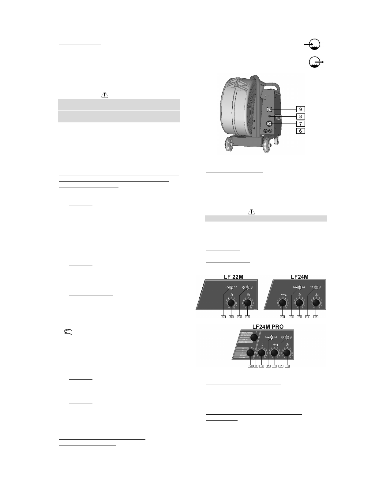
Deutsch Deutsch3
1. EURO-Anschluss: Zum Anschluss des Brenners.
2. Einstellknopf für den Drahtvorschub (WFS):
Ermöglicht die stufenlose Regelung des
Drahtvorschubes im Bereich von 1.0 bis 20m/min im
Handbetrieb oder eine Korrektur um +/-50% des
Vorschubes im synergetischen Betrieb der
Maschine.
WARNUNG
Vor dem Zünden des Lichtbogens und während des
Kaltdrahteinfädelns wirkt sich die eingestellte
Einschleichgeschwindigkeit [12] ebenfalls auf die
Drahtvorschubgeschwindigkeit aus.
3. Thermischer Überhitzungsanzeiger: Diese Lampe
leuchtet auf, wenn die Maschine überhitzt ist und
die Ausgangsleistung abgeschaltet ist. Lassen Sie
die Maschine eingeschaltet. So können die internen
Komponenten abkühlen. Erlischt die Warnleuchte,
kann das Gerät wieder betrieben werden.
4. Digital-Anzeige-Panel (Nur bei den Modellen LF24M
und LF 24M PRO. Beim Modell LF22M optional
verfügbar siehe Zubehör):
LF24M PRO:
• Display A: Zeigt den aktuellen Wert, und nach
Beendigung des Schweißvorgangs, den
Mittelwert des Schweißstromes (in A) an.
Wenn die Drahtvorschubgeschwindigkeit
ausgewählt ist [2], zeigt das Display die
eingestellte Vorschubgeschwindigkeit (in
m/min) – für manuelle Einstellung oder
Korrektur der automatisch eingestellten
Geschwindigkeit der Maschine im Bereich von
0.75-1.25 im Synergic-Modus an.
• Display V: Zeigt den aktuellen Wert und nach
Beendigung des Schweißvorganges den
Mittelwert der Schweißspannung (in V) an.
Wenn die Drahtvorschubgeschwindigkeit
ausgewählt wurde [2], erfolgt keine Anzeige.
• Zustandsanzeigen: Die Lampen zeigen den
aktuellen Modus der Maschine an:
SYNERGIC
Wenn diese Lampe leuchtet, dann
arbeitet die Maschine im Synergic
(synergetischen) Betrieb.
Wenn diese Lampe leuchtet, dann
arbeitet die Maschine im Handbetrieb.
Stellen Sie die gewünschte Arbeitsweise mit Hilfe
des Bedienknopfes für Schweißmaterial und
Gasgemisch ein [11].
LF24M:
• Display A: Zeigt den aktuellen Schweissstrom
(A) an, nach Beendigung des Schweissprozess
wird der Durchschnittswert des Schweissstroms
angezeigt.
• Display V: Zeigt den aktuellen
Schweissspannung (V) an, nach Beendigung
des Schweissprozess wird der
Durchschnittswert der Schweissspannung
angezeigt.
5. Schnellkupplungsanschlüsse (Nur bei
wassgerkühlter Version): Zum Anschuß
wassergekühlter MAG-Brenner.
Erwärmtes Wasser vom Brenner.
Kaltes Wasser zum Brenner.
6. Schnellkupplungsanschlüsse (Nur bei
wassgerkühlter Version): Bei Verwendung eines
wassergekühlten Brenners werden hier die
Wasserschläuche angeschlossen. Beachten Sie
die Kennzeichnung an Brenner und Kühlgerät
entsprechend der empfohlenen Flußrichtung des
Kühlmittels.
WARNUNG
Max. Druck der Kühlflüssigkeit ist 4 Bar.
7. Dinse-Schnellkupplungsstecker: Verbindung für
Eingangsstrom.
8. Gasanschluss: Anschluss für Gasschlauch.
9. Amphenol-Stecker: 8-poliger-Stecker zur
Stromquelle.
10. Einstellknopf Drahtdurchmesser: Ermöglicht die
Einstellung des Drahtdurchmessers, für den
Schweißprozess. Dieses Merkmal ist nur im
synergetischen Betrieb verfügbar.
11. Einstellknopf Wahl Schweißwerkstoff und
Gasgemisch : Ermöglicht:
• Auswahl des Schweißwerkstoffes und des dafür
geeigneten Gasgemisches.
• Einstellung von Handbetrieb oder synergischer
Arbeitsweise.
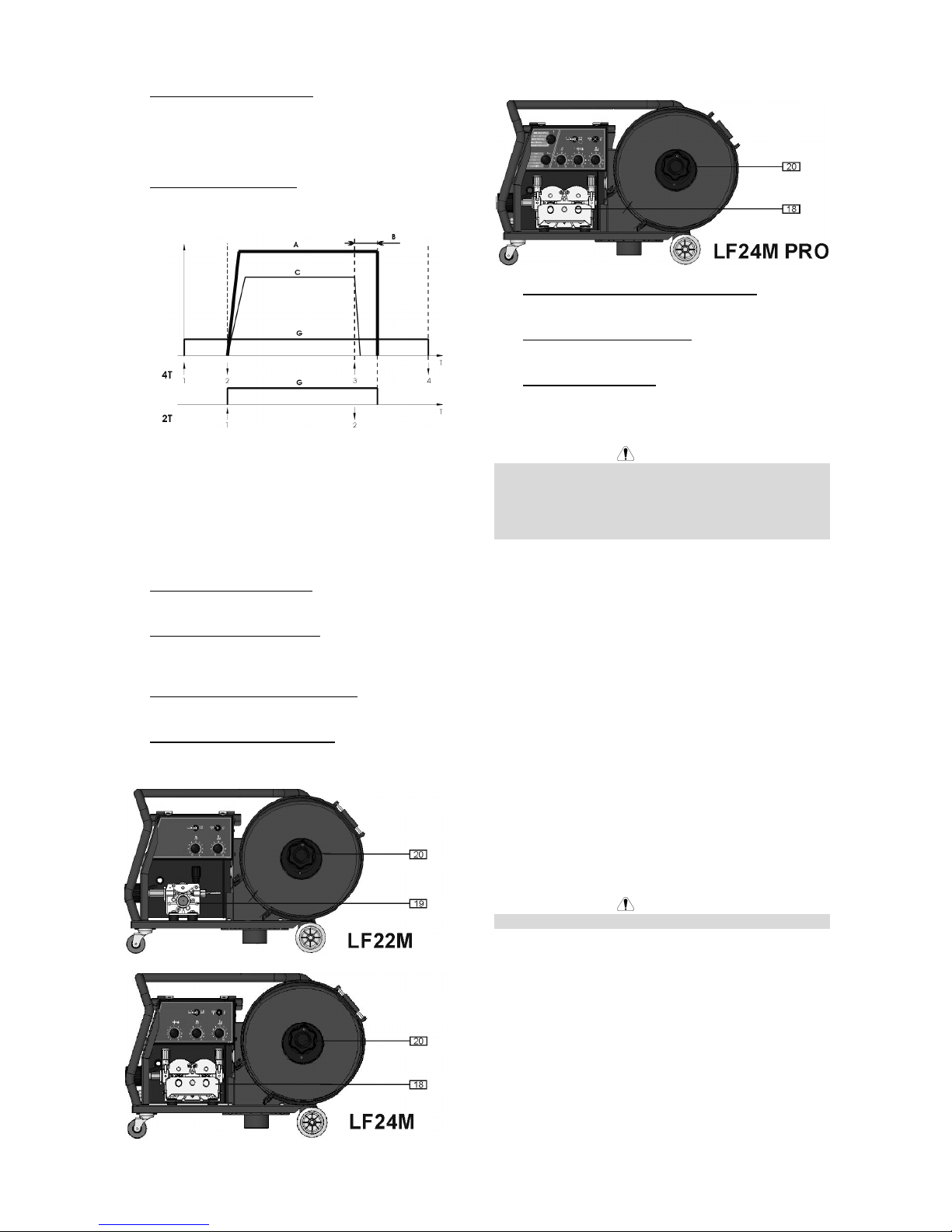
Deutsch Deutsch4
12. Einschleichgeschwindigkeit: Ermöglicht die
Einstellung der Drahtvorschub-Geschwindigkeit vor
Beginn des Schweißvorganges im Bereich von 0.1
bis 1.0 des Wertes, der durch den WFS
(Drahtvorschub)-Knopf [2] eingestellt ist.
13. Brenner-Modus-Schalter: Hiermit kann man den 2oder 4-Takt –Betrieb wählen. Die Arbeitsweise des
2-/4-Takt-Modus sehen Sie in der Abbildung unten:
↑
Brenner-Taster gedrückt
↓
Brenner-Taster nicht gedrückt
A. Schweiß-Strom.
B. Rückbrandzeit.
C. WFS.
G. Gas.
14. Rückbrenn-Zeit-Einstellung: Regelt die Drahtlänge
nach Beendigung der Schweißzeit von 8 bis 250ms.
15. Einfädeln / Gastest–Schalter: Dieser Schalter
erlaubt Drahtvorschub und Gastest ohne
Schweißspannung.
16. Stellknopf für die Punktschweißzeit: Er ermöglicht
eine Zeiteinstellung von 0.2 bis 10 s.
17. Gas Vorlauf (nur LF 24M PRO): Bestimmt die Zeit
zwischen Beginn des Gas-und Beginn der
Stromfluss von 0,01 bis 1s.
18. Drahtvorschub (nur LF 24M, 24M PRO): 4Rollenantrieb passend für 37 mm Vorschubrollen.
19. Drahtvorschub (nur LF 22M): 2-Rollen-Antrieb
passend für 37 mm Vorschubrollen.
20. Drahtspulenaufnahme: Maximal 15 kg Spulen.
Geeignet für Plastik-, Stahl- and Fiberspulen mit 51
mm Spindel. Genauso können Korbspulen mit
entsprechendem Adapter verwendet werden.
WARNUNG
Die Linc Feed Drahtvorschubgeräte dürfen nur mit
geschlossener Klappe betrieben werden.
Nutzen Sie die Griffe nicht zum Transport während der
Drahtvorschub betrieben wird.
Bestückung der Maschine mit der
Drahtelektrode
Öffnen Sie die Seitenabdeckung der Maschine.
Lösen Sie die Befestigungskappe von der Hülse.
Stecken Sie die Spule mit dem Draht so auf die Hülse,
dass sich die Spule beim Einführen des Drahtes in die
Drahtzuführung im Uhrzeigersinn dreht.
Gewährleisten Sie, dass die Paßfeder in die Bohrung
der Spule eingeführt wird.
Schrauben Sie die Befestigungskappe wieder auf.
Verwenden Sie beim Aufstecken der Drahtrolle die
richtige Nut, die mit dem Drahtdurchmesser
übereinstimmt.
Legen Sie das Drahtende frei und schneiden Sie das
gebogene Ende ab. Es darf kein Grat vorhanden sein.
WARNUNG
Scharfe Drahtenden können zu Verletzungen führen.
Drehen Sie die Spule in Uhrzeigerrichtung und führen
Sie den Draht in die Vorschubeinheit sowie den EuroAnschluß ein.
Stellen Sie die Spannung an der Druckrolle der
Drahtvorschubeinheit ein.
Bremseneinstellung der Spulen - Achse
Um unkontrolliertes Abrollen des Schweißdrahtes zu
vermeiden, ist die Spulen-Achse mit einer Bremse
ausgestattet.
Eingestellt wird die Bremse mit einer Schraube M10, an
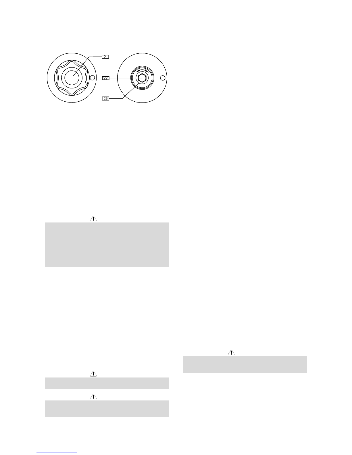
Deutsch Deutsch5
der Innenseite der Achse. Diese Schraube ist sichtbar
nach Entfernung der Befestigungsschraube der SpulenAchse.
21. Befestigungsschraube.
22. Einstellschraube M10.
23. Druckfeder.
Der Federdruck nimmt zu, wenn die Schraube im
Uhrzeigersinn gedreht wird. Die Bremskraft nimmt dann
auch zu.
Wenn Sie die Schraube gegen den Uhrzeiger drehen,
nehmen der Federdruck und die Bremskraft ab.
Nach dem Einstellen kann man die Befestigungsschraube wieder anbringen.
Einstellung Druck Drahtvorschubrolle
Die Druckkraft wird durch Drehen der Einstellmutter
verändert; in Uhrzeigerrichtung wird diese erhöht, entgegen der Uhrzeigerrichtung wird die Kraft verringert.
WARNUNG
Ist die Drahtspannung zu niedrig, gleitet die
Vorschubrolle über den Draht. Ist die Drahtspannung zu
hoch, besteht die Gefahr, dass der Draht sich verformt.
Dies kann zu Vorschubproblemen im Brenner führen.
Es muss also unbedingt die richtige Spannung
eingestellt werden. Verringern Sie die Spannung, bis die
Rolle anfängt zu gleiten. Drehen Sie dann die
Schrauben einen Schlag im Uhrzeigersinn.
Einfädeln des Drahtes in den SchweißBrenner
Schließen Sie einen geeigneten Schweißbrenner an den
Euro-Anschluß an. Die Parameter für Brenner und
Schweißquelle müssen übereinstimmen.
Entfernen Sie die Gasdüse und die Stromkontaktdüse
vom Schweißbrenner.
Stellen Sie den Drahtvorschub mit Hilfe des WFSKnopfes [2] auf etwa 10m/min ein.
Stellen Sie den Schalter Manueller
Drahtvorschub/Gastest [15] in die "Manueller VorschubStellung" und halten diese solange, bis die Elekrode aus
der Kontaktdüse des Schweißbrenners herausschaut.
WARNUNG
Halten Sie das Brennerende in sicherer Entfernung von
Augen und Händen, während der Draht zugeführt wird.
WARNUNG
Schalten Sie, sobald der Draht in dem Brenner
eingefädelt ist, die Stromvesorgung ab, bevor Sie
Kontakt- und Gasverteiler wieder montieren.
Manuelles MIG / MAG-Schweißen
Damit Sie manuell MIG/MAG-schweißen können,
müssen Sie:
• Die Maschine mit angeschlossenem
Drahtvorschubgerät einschalten.
• Drahteinfädeln mit "cold inch"-Schaltung [15].
• Kontrollieren Sie den Gasstrom mit der "Gas-
Purge"-Schaltung [15].
• Schalten Sie den Knopf [11] (nur LF 24M PRO) auf
Manual-Position (Überprüfen Sie ob das Panel [4]
den Manual-Modus anzeigt).
• Wählen Sie eine dem Schweißprozess und der
Materialstärke angepasste Spannungsstufe und die
Vorschubgeschwindigkeit mit Knopf [2].
• Die Maschine ist nun schweißbereit.
Stromquellenauswahl (nur LF 24M
PRO)
Das Drahtvorschubgerät LF 24M PRO kann mit
folgenden Stromquellen im Synergic-Modus arbeiten:
• Powertec 305S
• Powertec 365S.
• Powertec 425S.
• Powertec 505S.
Das Gerät ist für die Powertec 425S voreingestellt
(Werkseinstellung).
Falls eine andere Stromquelle eingesetzt wird, sind
folgende Schritte durchzuführen:
• Schalten Sie die Stromversorgung des
Vorschubgerätes ab.
• Schalten Sie den Knopf für die
Drahtdurchmesserwahl [10] auf "1.6 CORE"Position. Setzen Sie den Knopf für Material- und
Gasart [11] in "MANUAL" Position.
• Schalten Sie die Stromversorgung des
Vorschubgerätes ein.
• Schalten Sie innerhalb von 15 s den Knopf für die
Drahtdurchmesserwahl [10] in "0.8" -Position und
den Knopf für Material- und Gasart [11] in " STEEL
(80%AR 20%CO
2
)" -Position (überprüfen Sie dass
das Display "V" "S" anzeigt).
• Nutzen Sie den Knopf [2] um die zugewiesene bzw.
korrekte Stromquelle auszuwählen:
• 305 S
• 365 S
• 425 S
• 505 S
• Sichern Sie die getroffene Auswahl durch setzen
der Drahtdurchmesser-Auswahl [10] auf "1.6
CORE"- Position – Das Drahtvorschubgerät ist
einsatzbereit.
WARNUNG
Das Display "V" zeigt die Nummer der ausgewählten
Stromquelle (305S/365S/425S/505S) für 2 s nach
Einschalten des Vorschubgerätes an.
Synergisches MIG / MAG-Schweißen
(nur LF 24M PRO)
Damit Sie synergisch MIG/MAG-schweißen können,
müssen Sie:
• Die Maschine mit angeschlossenem Vorschubgerät
einschalten.
• Drahteinfädeln mit "cold inch"-Schaltung [15].
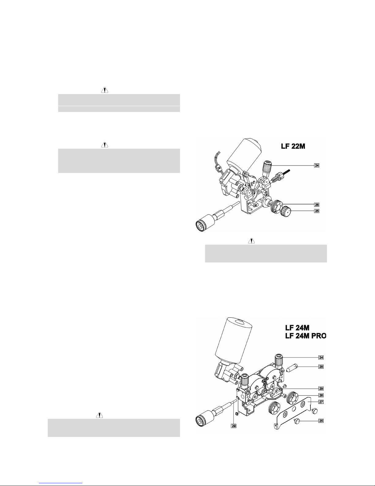
Deutsch Deutsch6
• Kontrollieren Sie den Gasstrom mit der "Gas-
Purge"-Schaltung [15].
• Den Wahlschalter für den Drahtdurchmesser [10] in
die Stellung für den Durchmesser des verwendeten
Drahtes drehen.
• Den Einstellknopf [11] für Schweißwerkstoff und
Gasgemisch in die für den verwendeten Werkstoff
erforderliche Stellung bringen.
WARNUNG
Wenn das ausgewählte Schweißverfahren keinen
synergetischen Modus besitzt, erscheinen auf der
Anzeige "A" drei waagerechte Striche.
• Entsprechend dem ausgewählten Schweiß-
programm und der Materialstärke, ist die passende
Spannungsstufe an der Stromquelle einzustellen.
WARNUNG
Bei synergischem Schweißmodus für alle
Positionen der Stromquelle, kann die automatische
Vorschubgeschwindigkeit im Bereich von ±50% am
Drahtvorschub-Stellknopf [2].korrigiert werden.
• Die Maschine ist nun schweißbereit.
Wasserkühler-Steuerung (nur LF 24M
PRO)
Das LF 24M PRO Vorschubgerät ermöglicht, das
Wasserkühlgerät automatisch mit der Powertec
365S/425S/505S zu steuern, d.h.:
• Beim Starten des Schweißvorganges wird das
Kühlgerät automatisch eingeschaltet.
• Nach Beendigung des Schweißvorganges läuft die
Wasserkühlung noch für 5 min. weiter, danach
schaltet diese sich ab.
• Wird innerhalb dieser 5 min erneut geschweißt.,
läuft die Wasserkühlung weiter.
Das Drahtfördergerät hat die Möglichkeit den
Automatikmodus des Wasserkühlgerätes abzuschalten
und statt dessen im Dauerbetrieb zu arbeiten. Falls der
Arbeitsmodus des Kühlgerätes verändert werden muß,
gehen Sie folgendermaßen vor:
• Schalten Sie die Stromquelle mit dem
angeschlossenen Vorschubgerät aus.
• Stellen Sie den Schalter zur Drahtdurchmesserwahl
[10] auf "1.0" -Position. Stellen Sie den Schalter zur
Material- und Gasauswahl [11] auf "CRNI (98%AR
2%CO
2
)" -Position.
• Schalten Sie die Stromversorgung des
Vorschubgerätes ein.
• Schalten Sie innerhalb von 15 s den Knopf für den
Drahtdurchmesser [10] auf "1.2" -Position und den
Knopf für Material- und Gasart [11] auf "STEEL
(100%CO
2
)" -Position – das Wasserkühlgerät ist
eingeschaltet und das Display "V" zeigt "on".
Falls zum Automatikmodus des Kühlgerätes
zurückgekehrt werden soll, ist genauso zu verfahren
(das Display “V” zeigt " 5'' ").
WARNUNG
Das Display "V" zeigt den Wasserkühlmodus (“5"/on) für
2 s an, nachdem die Stromversorgung des
Vorschubgerätes eingeschaltet wurde.
Auswechseln der Antriebsrollen
Das Vorschubgerät ist mit Antriebsrollen für 1.0 und 1.2
mm (für LF 24M/24M PRO) oder 0.8 und 1.0 mm (für LF
22M) ausgestattet. Für andere Drahtstärken ist es
möglich, die passenden Rollensätze auszuwechseln
(siehe Kapitel Zubehör für die Bestellung der
gewünschten Sätze). Die Antriebsrollen werden
folgendermaßen gewechselt:
• Schalten Sie die Schweißstromquelle, an der das
Vorschubgerät angeschlossen ist, ab.
• Lösen Sie den Hebel für die Druckrolle [24].
• Lösen Sie die Befestigungskappe [25].
• Öffnen Sie die Schutzabdeckung [27].
• Ersetzen Sie die bisherigen Antriebsrollen [26]
durch die Neuen.
WARNUNG
Für Drahtdurchmesser größer als 1.6 mm (nur für
LF 24M/24M PRO), müssen folgende Teile mit
ausgetauscht werden:
• Das Führungsrohr für die Vorschubkonsole [28]
und [29].
• Das Führungsrohr für den Euro-Anschluß [30].
• Ersetzen Sie die Schutzabdeckung [27] und
schrauben Sie diese an die Antriebsrollen an.
• Befestigen Sie die Schutzabdeckung mit den
Befestigungsschrauben [25].
Deutsch Deutsch7
Wartung
WARNUNG
Für Wartung und Reparatur des Gerätes konsultieren
Sie bitte Ihren Fachhändler oder die Lincoln Electric.
Eine unsachgemäß durchgeführte Wartung oder
Reparatur durch eine nicht qualifizierte Person führt zum
Erlöschen der Garantie.
Die Wartungsintervalle können abhängig von den
Arbeitsbedingungen der Maschine schwanken.
Ein schwerwiegender Schaden ist unverzüglich zu
melden.
Laufende Wartung
• Prüfen Sie den Anschluß und die Isolation des
Massekabels und Versorgungskabels.
• Entfernen Sie Schweißspritzer von der Schweiß-
düse. Schweißspritzer können den Fluß des
Schutzgases von der Schweißdüse zum Lichtbogen
beeinflussen.
• Überprüfen Sie den Zustand der Düse und ersetzen
Sie diese, wenn erforderlich.
• Überprüfen Sie Zustand und Betrieb des Lüfters –
halten Sie dessen Lüftungsschlitze frei und sauber.
Periodische Wartung
Zusätzlich zur laufenden Wartung sind folg. Arbeiten
durchzuführen:
• Halten Sie die Maschine sauber. Verwenden Sie
einen trockenen Luftstrom mit geringem Luftdruck.
Entfernen Sie den Staub von der äußeren Abdeckung und aus dem Innern des Gehäuses.
• Überprüfen Sie alle Anschlüsse und ersetzen Sie
diese falls erforderlich.
• Überprüfen Sie alle Schrauben auf festen Sitz und
ziehen Sie diese nach, wenn erforderlich.
WARNUNG
Die Maschine muß während der Durchführung der
Wartungsarbeiten vom Netz getrennt sein. Nach jeder
Reparatur sind geeignete Tests durchzuführen, um die
Betriebssicherheit zu überprüfen.
Elektromagnetische Verträglichkeit (EMC)
11/04
Diese Maschine wurde unter Beachtung aller zugehörigen Normen und Vorschriften gebaut. Dennoch kann es unter
besonderen Umständen zu elektromagnetischen Störungen anderer elektronischer Syteme (z.B. Telefon, Radio, TV,
Computer usw.) kommen. Diese Störungen können im Extremfall zu Sicherheitsproblemen der beeinflussten Systeme
führen. Lesen Sie deshalb diesen Abschnitt aufmerksam durch, um das Auftreten elektromagnetischer Störungen zu
reduzieren oder ganz zu vermeiden.
Diese Maschine ist für den industriellen Einsatz konzipiert worden. Bei Benutzung dieser Anlage in Wohngebieten sind
daher besondere Vorkehrungen zu treffen, um Störungen durch elektromagnetische Beeinflussungen zu
vermeiden. Halten Sie sich stets genau an die in dieser Bedienungsanleitung genannten
Einsatzvorschriften. Falls dennoch elektromagnetische Störungen auftreten, müssen geeignete
Gegenmaßnahmen getroffen werden. Kontaktieren Sie gegebenenfalls den Kundendienst der Lincoln
Electric. Technische Änderungen der Anlage sind nur nach schriftlicher Genehmigung des Herstellers zulässig.
Vergewissern Sie sich vor der Inbetriebnahme des Schweißgerätes, dass sich keine für elektromagnetische Störungen
empfänglichen Geräte und Anlagen im möglichen Einflussbereich befinden. Dies gilt besonders für:
• Steuerleitungen, Datenkabel und Telefonleitungen.
• Radio und Televisions-Sender oder -Empfänger sowie deren Kabelverbindungen. Computer oder
computergesteuerte Anlagen.
• Elektronische Sicherheitseinrichtungen und Steuereinheiten für industrielle Anlagen. Elektronische Mess- und
Kalibriereinrichtungen.
• Medizinische Apparate und Geräte, Hörgeräte oder persönliche Implantate wie Herzschrittmacher usw. Achtung!
Informieren Sie sich vor Inbetriebnahme der Anlage in der Nähe von Kliniken und Krankenhäusern über die hierzu
gültigen Vorschriften, und sorgen Sie für die exakte Einhaltung aller erforderlichen Sicherheitsmaßnahmen!
• Prüfen Sie grundsätzlich die elektromagnetische Verträglichkeit von Geräten, die sich im Einflussbereich der
Schweißanlage befinden.
• Dieser Einflussbereich kann in Abhängigkeit der physikalischen Umstände in seiner räumlichen Ausdehnung stark
variieren.
Befolgen Sie zusätzlich die folgenden Richtlinien um elektromagnetische Abstrahlungen zu reduzieren:
• Schließen Sie die Maschine stets nur wie beschrieben an. Falls dennoch Störungen auftreten, muss eventuell ein
zusätzlicher Netzfilter eingebaut werden.
• Halten Sie die Länge der Schweißkabel möglichst auf ein erforderliches Mindestmaß begrenzt. Wenn möglich,
sollte das Werkstück separat geerdet werden. Beachten Sie stets bei allen Maßnahmen, dass hierdurch keinerlei
Gefährdung von direkt oder indirekt beteiligten Menschen verursacht wird.
• Abgeschirmte Kabel im Arbeitsbereich können die elektromagnetische Abstrahlung reduzieren. Dies kann je nach
Anwendung notwendig sein.
 Loading...