

Lincoln Electric LINC 405-S, LINC 405-SA Operator's Manual
IM3001
08/2006
Rev. 6
LINC 405
OPERATOR’S MANUAL
MANUALE OPERATIVO
BEDIENUNGSANLEITUNG
MANUAL DE INSTRUCCIONES
MANUEL D'UTILISATION
BRUKSANVISNING OG DELELISTE
GEBRUIKSAANWIJZING
BRUKSANVISNING
INSTRUKCJA OBSŁUGI
KÄYTTÖOHJE
LINCOLN ELECTRIC BESTER S.A.
ul. Jana III Sobieskiego 19A, 58-260 Bielawa, Poland
www.lincolnelectriceurope.com

II
Declaration of conformity
Dichiarazione di conformità
Konformitätserklärung
Declaración de conformidad
Déclaration de conformité
Samsvars erklæring
Verklaring van overeenstemming
Försäkran om överensstämmelse
Deklaracja zgodności
Vakuutus yhteensopivuudesta
LINCOLN ELECTRIC BESTER S.A.
Declares that the welding machine:
Dichiara che Il generatore per saldatura tipo:
Erklärt, daß die Bauart der Maschine:
Declara que el equipo de soldadura:
Déclare que le poste de soudage:
Bekrefter at denne sveisemaskin:
Verklaart dat de volgende lasmachine:
Försäkrar att svetsomriktaren:
Deklaruje, że spawalnicze źródło energii:
Vakuuttaa, että hitsauskone:
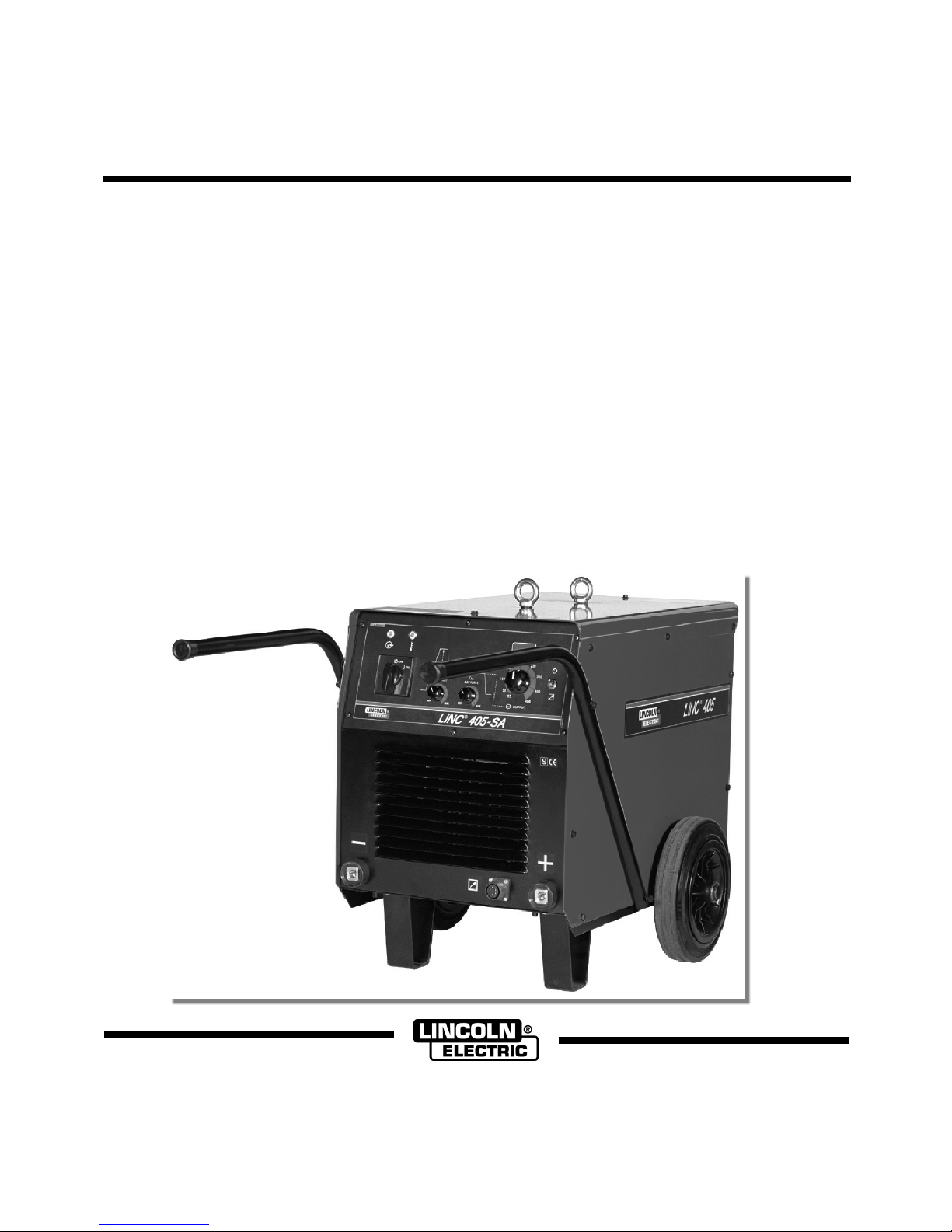
LINC 405-S, LINC 405-SA
conforms to the following directives:
è conforme alle seguenti direttive:
den folgenden Bestimmungen entspricht:
es conforme con las siguientes directivas:
est conforme aux directives suivantes:
er i samsvar med følgende direktiver:
overeenkomt conform de volgende richtlijnen:
överensstämmer med följande direktiv:
spełnia następujące wytyczne:
täyttää seuraavat direktiivit:
73/23/CEE, 89/336/CEE
and has been designed in compliance with the following
standards:
ed è stato progettato in conformità alle seguenti norme:
und in Übereinstimmung mit den nachstehenden normen
hergestellt wurde:
y ha sido diseñado de acuerdo con las siguientes
normas:
et qu'il a été conçu en conformité avec les normes:
og er produsert og testet iht. følgende standarder:
en is ontworpen conform de volgende normen:
och att den konstruerats i överensstämmelse med
följande standarder:
i że zostało zaprojektowane zgodnie z wymaganiami
następujących norm:
ja on suunniteltu seuraavien standardien mukaan:
EN 60974-1, EN 60974-10
(2003)
Tomasz Domagalski
Operations Director
LINCOLN ELECTRIC BESTER S.A., ul. Jana III Sobieskiego 19A, 58-260 Bielawa, Poland
12/05

III
12/05
THANKS! For having choosen the QUALITY of the Lincoln Electric products.
• Please Examine Package and Equipment for Damage. Claims for material damaged in shipment must be notified
immediately to the dealer.
• For future reference record in the table below your equipment identification information. Model Name, Code & Serial
Number can be found on the machine rating plate.
GRAZIE! Per aver scelto la QUALITÀ dei prodotti Lincoln Electric.
• Esamini Imballo ed Equipaggiamento per rilevare eventuali danneggiamenti. Le richieste per materiali danneggiati dal
trasporto devono essere immediatamente notificate al rivenditore.
• Per ogni futuro riferimento, compilare la tabella sottostante con le informazioni di identificazione equipaggiamento.
Modello, Codice (Code) e Matricola (Serial Number) sono reperibili sulla targa dati della macchina.
VIELEN DANK! Dass Sie sich für ein QUALITÄTSPRODUKT von Lincoln Electric entschieden haben.
• Bitte überprüfen Sie die Verpackung und den Inhalt auf Beschädigungen. Transportschäden müssen sofort dem Händler
gemeldet werden.
• Damit Sie Ihre Gerätedaten im Bedarfsfall schnell zur Hand haben, tragen Sie diese in die untenstehende Tabelle ein.
Typenbezeichnung, Code- und Seriennummer finden Sie auf dem Typenschild Ihres Gerätes.
GRACIAS! Por haber escogido los productos de CALIDAD Lincoln Electric.
• Por favor, examine que el embalaje y el equipo no tengan daños. La reclamación del material dañado en el transporte
debe ser notificada inmediatamente al proveedor.
• Para un futuro, a continuación encontrará la información que identifica a su equipo. Modelo, Code y Número de Serie los
cuales pueden ser localizados en la placa de características de su equipo.
MERCI! Pour avoir choisi la QUALITÉ Lincoln Electric.
• Vérifiez que ni l’équipement ni son emballage ne sont endommagés. Toute réclamation pour matériel endommagé doit
être immédiatement notifiée à votre revendeur.
• Notez ci-dessous toutes les informations nécessaires à l’identification de votre équipement. Le nom du Modèle ainsi que
les numéros de Code et Série figurent sur la plaque signalétique de la machine.
TAKK! For at du har valgt et KVALITETSPRODUKT fra Lincoln Electric.
• Kontroller emballsjen og produktet for feil eller skader. Eventuelle feil eller transportskader må umiddelbart rapporteres
dit du har kjøpt din maskin.
• For fremtidig referanse og for garantier og service, fyll ut den tekniske informasjonen nedenfor i dette avsnittet. Modell
navn, Kode & Serie nummer finner du på den tekniske platen på maskinen.
BEDANKT! Dat u gekozen heeft voor de KWALITEITSPRODUCTEN van Lincoln Electric.
• Controleert u de verpakking en apparatuur op beschadiging. Claims over transportschade moeten direct aan de dealer of
aan Lincoln electric gemeld worden.
• Voor referentie in de toekomst is het verstandig hieronder u machinegegevens over te nemen. Model Naam, Code &
Serienummer staan op het typeplaatje van de machine.
TACK! För att ni har valt en KVALITETSPRODUKT från Lincoln Electric.
• Vänligen kontrollera förpackning och utrustning m.a.p. skador. Transportskador måste omedelbart anmälas till
återförsäljaren eller transportören.
• Notera informationen om er utrustnings identitet i tabellen nedan. Modellbeteckning, code- och serienummer hittar ni på
maskinens märkplåt.
DZIĘKUJEMY! Za docenienie JASKOŚCI produktów Lincoln Electric.
• Proszę sprawdzić czy opakownie i sprzęt nie są uszkodzone. Reklamacje uszkodzeń powstałych podczas transportu
muszą być natychmiast zgłoszone do dostawcy (dystrybutora).
• Dla ułatwienia prosimy o zapisanie na tej stronie danych identyfikacyjnych wyrobów. Nazwa modelu, Kod i Numer
Seryjny, które możecie Państwo znaleźć na tabliczce znamionowej wyrobu.
KIITOS! Kiitos, että olet valinnut Lincoln Electric LAATU tuotteita.
• Tarkista pakkaus ja tuotteet vaurioiden varalta. Vaateet mahdollisista kuljetusvaurioista on ilmoitettava välittömästi
jälleenmyyjälle.
• Tulevaisuutta varten täytä alla oleva lomake laitteen tunnistusta varten. Mallin, Koodin ja Sarjanumeron voit löytää
konekilvestä.
Model Name, Modello, Typenbezeichnung, Modelo, Nom du modèle, Modell navn, Model Naam, Modellbeteckning, Nazwa
modelu, Mallinimi:
………………...…………………………….…………………………………………………………………………………………..
Code & Serial number, Code (codice) e Matricola, Code- und Seriennummer, Code y Número de Serie, Numéros de Code et
Série, Kode & Serie nummer, Code en Serienummer, Code- och Serienummer, Kod i numer Seryjny, Koodi ja Sarjanumero:
………………….……………………………………………….. …………………………………………………….……………..
Date & Where Purchased, Data e Luogo d’acquisto, Kaufdatum und Händler, Fecha y Nombre del Proveedor, Lieu et Date
d’acquisition, Kjøps dato og Sted, Datum en Plaats eerste aankoop, Inköpsdatum och Inköpsställe, Data i Miejsce zakupu,
Päiväys ja Ostopaikka:
…………………………………………………………………... ……………………….…………………………………………..

IV
ENGLISH INDEX
Safety.................................................................................................................................................................................................... A-1
Installation and Operator Instructions ................................................................................................................................................... A-2
Electromagnetic Compatibility (EMC) ................................................................................................................................................... A-4
Technical Specifications ....................................................................................................................................................................... A-4
INDICE ITALIANO
Sicurezza .............................................................................................................................................................................................. B-1
Installazione e Istruzioni Operative....................................................................................................................................................... B-2
Compatibilità Elettromagnetica (EMC).................................................................................................................................................. B-4
Specifiche Tecniche.............................................................................................................................................................................. B-5
INHALTSVERZEICHNIS DEUTSCH
Sicherheitsmaßnahmen / Unfallschutz ................................................................................................................................................. C-1
Installation und Bedienungshinweise.................................................................................................................................................... C-2
Elektromagnetische Verträglichkeit (EMC) ........................................................................................................................................... C-4
Technische Daten.................................................................................................................................................................................C-5
INDICE ESPAÑOL
Seguridad.............................................................................................................................................................................................. D-1
Instalación e Instrucciones de Funcionamiento.................................................................................................................................... D-2
Compatibilidad Electromagnética (EMC)..............................................................................................................................................D-4
Especificaciones Técnicas.................................................................................................................................................................... D-5
INDEX FRANÇAIS
Sécurité................................................................................................................................................................................................. E-1
Installation et Instructions d'Utilisation.................................................................................................................................................. E-2
Compatibilité Electromagnétique (CEM)............................................................................................................................................... E-4
Caractéristiques Techniques ................................................................................................................................................................E-5
NORSK INNHOLDSFORTEGNELSE
Sikkerhetsregler.....................................................................................................................................................................................F-1
Installasjon og Brukerinstruksjon ...........................................................................................................................................................F-2
Elektromagnetisk Kompatibilitet (EMC) .................................................................................................................................................F-4
Tekniske Spesifikasjoner .......................................................................................................................................................................F-5
NEDERLANDSE INDEX
Veiligheid ..............................................................................................................................................................................................G-1
Installatie en Bediening.........................................................................................................................................................................G-2
Elektromagnetische Compatibiliteit (EMC) ...........................................................................................................................................G-4
Technische Specificaties ......................................................................................................................................................................G-5
SVENSK INNEHÅLLSFÖRTECKNING
Säkerhetsanvisningar ...........................................................................................................................................................................H-1
Instruktioner för Installation och Handhavande .................................................................................................................................... H-2
Elektromagnetisk Kompatibilitet (EMC) ................................................................................................................................................ H-4
Tekniska Specifikationer.......................................................................................................................................................................H-5
SKOROWIDZ POLSKI
Bezpieczeństwo Użytkowania ................................................................................................................................................................I-1
Instrukcja Instalacji i Eksploatacji ...........................................................................................................................................................I-2
Kompatybilność Elektromagnetyczna (EMC) .........................................................................................................................................I-4
Dane Techniczne....................................................................................................................................................................................I-5
SISÄLLYSLUETTELO
Turvallisuus............................................................................................................................................................................................J-1
Asennus ja Käyttöohjeet ........................................................................................................................................................................J-2
Elektromagneettinen Yhteensopivuus (EMC)........................................................................................................................................J-4
Tekniset Tiedot ......................................................................................................................................................................................J-4
Spare Parts, Parti di Ricambio, Ersatzteile, Lista de Piezas de Recambio, Pièces de Rechange, Deleliste, Reserve Onderdelen,
Reservdelar, Wykaz Części Zamiennych, Varaosaluettelo ......................................................................................................................1
Electrical Schematic, Schema Elettrico, Elektrische Schaltpläne, Esquema Eléctrico, Schéma Electrique, Elektrisk Skjema, Elektrisch
Schema, Elektriskt Kopplingsschema, Schemat Elektryczny, Sähkökaavio ............................................................................................4
Accessories, Accessori, Zubehör, Accesorios, Accessoires, Tilleggsutstyr, Accessores, Tillbehör, Akcesoria, Varusteet .....................5
A
-1
Safety
11/04
WARNING
This equipment must be used by qualified personnel. Be sure that all installation, operation, maintenance and repair
procedures are performed only by qualified person. Read and understand this manual before operating this equipment.
Failure to follow the instructions in this manual could cause serious personal injury, loss of life, or damage to this
equipment. Read and understand the following explanations of the warning symbols. Lincoln Electric is not responsible
for damages caused by improper installation, improper care or abnormal operation.
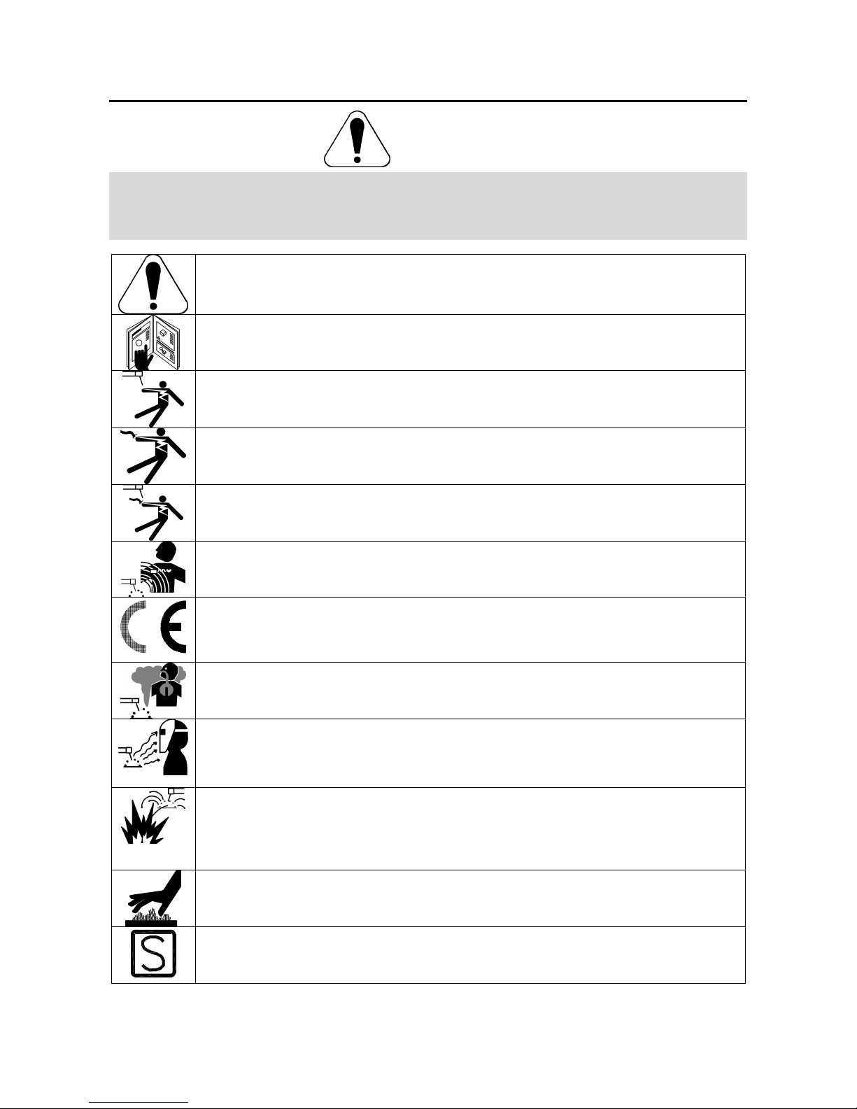
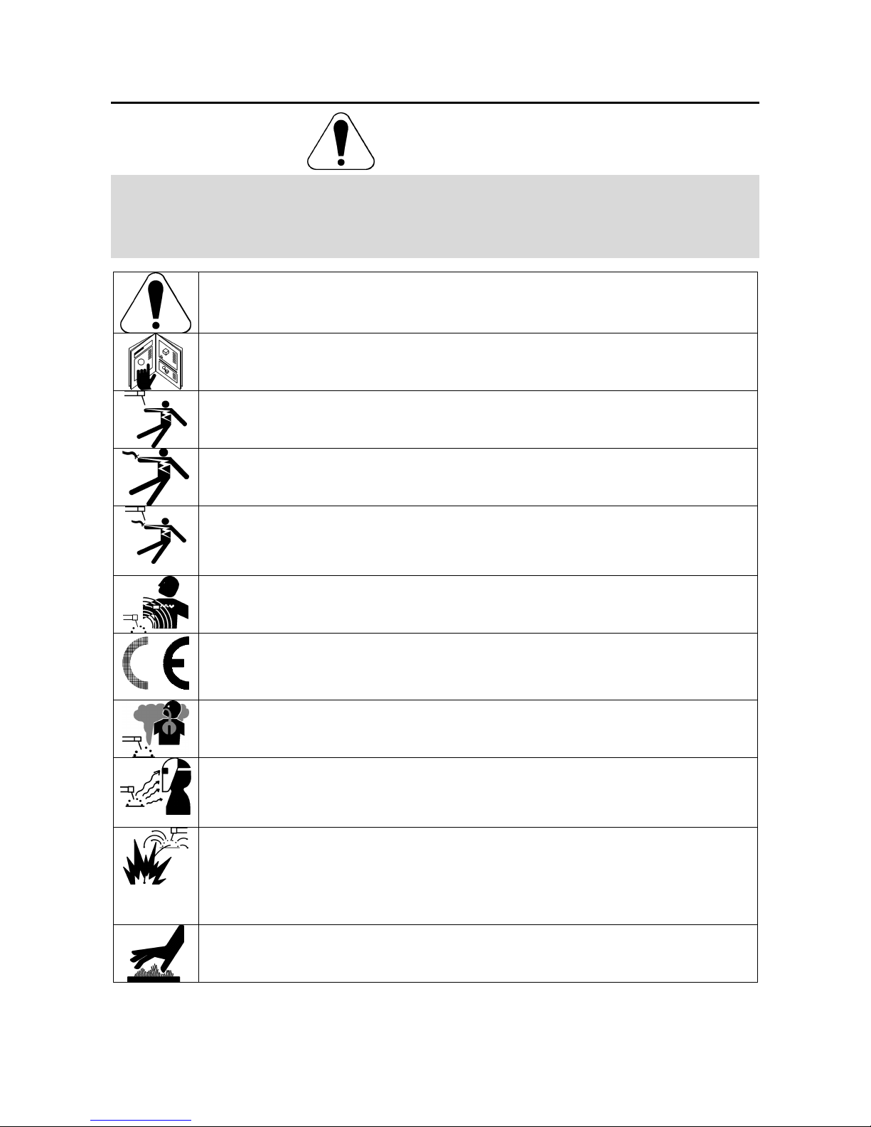
WARNING: This symbol indicates that instructions must be followed to avoid serious personal injury,
loss of life, or damage to this equipment. Protect yourself and others from possible serious injury or
death.
READ AND UNDERSTAND INSTRUCTIONS: Read and understand this manual before operating
this equipment. Arc welding can be hazardous. Failure to follow the instructions in this manual could
cause serious personal injury, loss of life, or damage to this equipment.
ELECTRIC SHOCK CAN KILL: Welding equipment generates high voltages. Do not touch the
electrode, work clamp, or connected work pieces when this equipment is on. Insulate yourself from
the electrode, work clamp, and connected work pieces.
ELECTRICALLY POWERED EQUIPMENT: Turn off input power using the disconnect switch at the
fuse box before working on this equipment. Ground this equipment in accordance with local electrical
regulations.
ELECTRICALLY POWERED EQUIPMENT: Regularly inspect the input, electrode, and work clamp
cables. If any insulation damage exists replace the cable immediately. Do not place the electrode
holder directly on the welding table or any other surface in contact with the work clamp to avoid the
risk of accidental arc ignition.
ELECTRIC AND MAGNETIC FIELDS MAY BE DANGEROUS: Electric current flowing through any
conductor creates electric and magnetic fields (EMF). EMF fields may interfere with some
pacemakers, and welders having a pacemaker shall consult their physician before operating this
equipment.
CE COMPLIANCE: This equipment complies with the European Community Directives.
FUMES AND GASES CAN BE DANGEROUS: Welding may produce fumes and gases hazardous to
health. Avoid breathing these fumes and gases. To avoid these dangers the operator must use
enough ventilation or exhaust to keep fumes and gases away from the breathing zone.
ARC RAYS CAN BURN: Use a shield with the proper filter and cover plates to protect your eyes from
sparks and the rays of the arc when welding or observing. Use suitable clothing made from durable
flame-resistant material to protect you skin and that of your helpers. Protect other nearby personnel
with suitable, non-flammable screening and warn them not to watch the arc nor expose themselves to
the arc.
WELDING SPARKS CAN CAUSE FIRE OR EXPLOSION: Remove fire hazards from the welding
area and have a fire extinguisher readily available. Welding sparks and hot materials from the welding
process can easily go through small cracks and openings to adjacent areas. Do not weld on any
tanks, drums, containers, or material until the proper steps have been taken to insure that no
flammable or toxic vapors will be present. Never operate this equipment when flammable gases,
vapors or liquid combustibles are present.
WELDED MATERIALS CAN BURN: Welding generates a large amount of heat. Hot surfaces and
materials in work area can cause serious burns. Use gloves and pliers when touching or moving
materials in the work area.
SAFETY MARK: This equipment is suitable for supplying power for welding operations carried out in
an environment with increased hazard of electric shock.
A
-2
Installation and Operator Instructions
Read this entire section before installation or operation
of the machine.
Location and Environment
This machine will operate in harsh environments.
However, it is important that simple preventative
measures are followed to assure long life and reliable
operation.
• Do not place or operate this machine on a surface
with an incline greater than 15° from horizontal.
• Do not use this machine for pipe thawing.
• This machine must be located where there is free
circulation of clean air without restrictions for air
movement to and from the air vents. Do not cover
the machine with paper, cloth or rags when
switched on.
• Dirt and dust that can be drawn into the machine
should be kept to a minimum.
• This machine has a protection rating of IP23. Keep
it dry when possible and do not place it on wet
ground or in puddles.
• Locate the machine away from radio controlled
machinery. Normal operation may adversely affect
the operation of nearby radio controlled machinery,
which may result in injury or equipment damage.
Read the section on electromagnetic compatibility in
this manual.
• Do not operate in areas with an ambient
temperature greater than 40°C.
Duty cycle and Overheating
The duty cycle of a welding machine is the percentage of
time in a 10 minute cycle at which the welder can
operate the machine at rated welding current.
60% duty cycle:
Welding for 6 minutes. Break for 4 minutes.
Excessive extension of the work duty cycle will cause
the thermal protection circuit to activate.
The welding machine is protected from overheating by a
thermostat. When the machine is overheated the output
of the machine will turn “OFF“, and the Thermal Indicator
Light will turn “ON“. When the machine has cooled to a
safe temperature the Thermal Indicator Light will go out
and the machine may resume normal operation.
Minutes or decrease
duty cycle
Input Supply Connection
Installation and mains outlet socket shall be made and
protected according to appropriate rules.
Check the input voltage, phase, and frequency supplied
to this machine before turning it on. Verify the
connection of grounding wires from the machine to the
input source. The allowable input voltages are 3x230V
and 3x400V 50Hz (400V: factory default). For more
information about input supply refer to the technical
specification section of this manual and to the rating
plate of the machine.
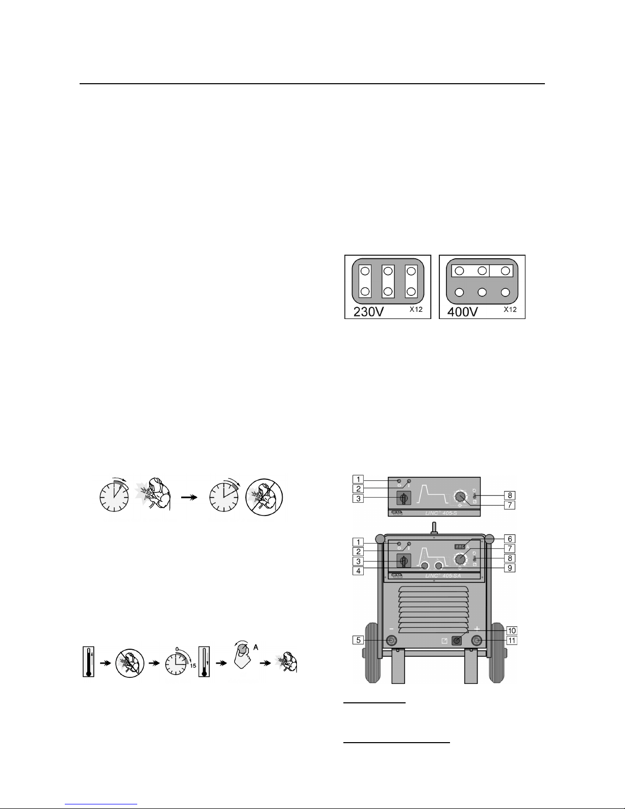
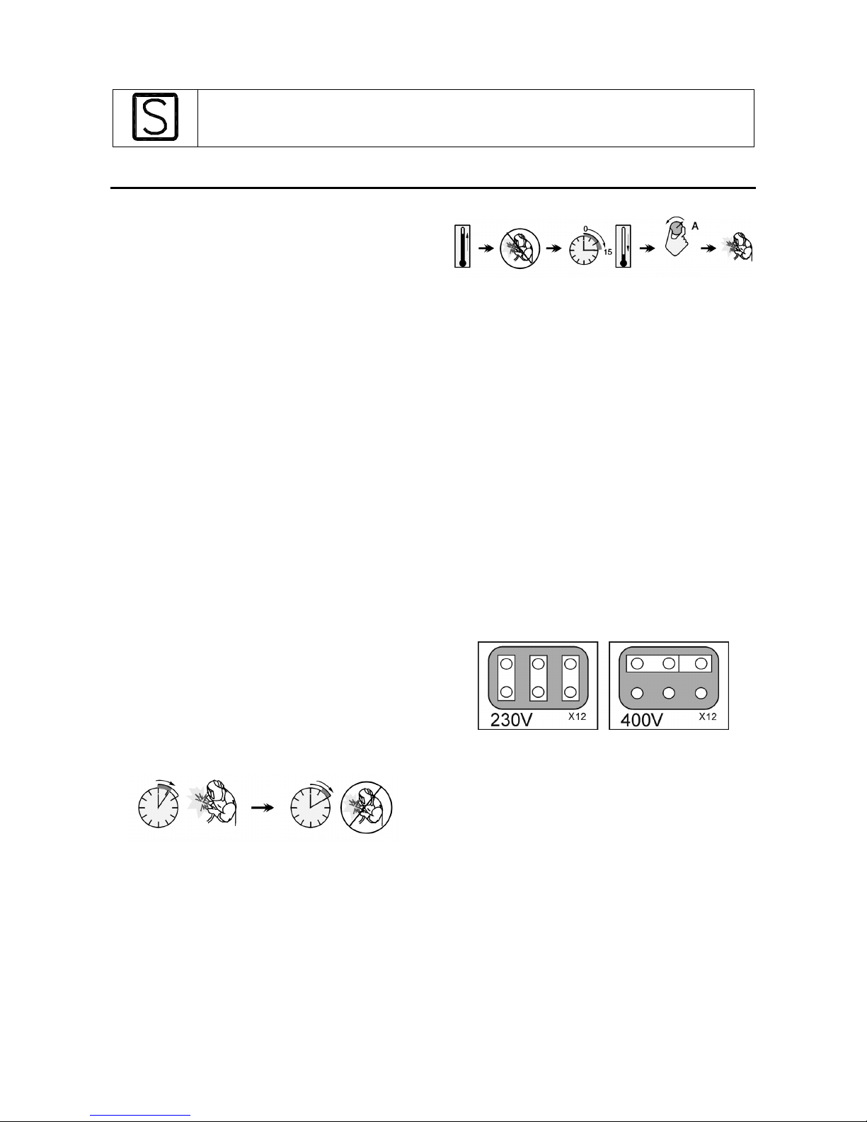
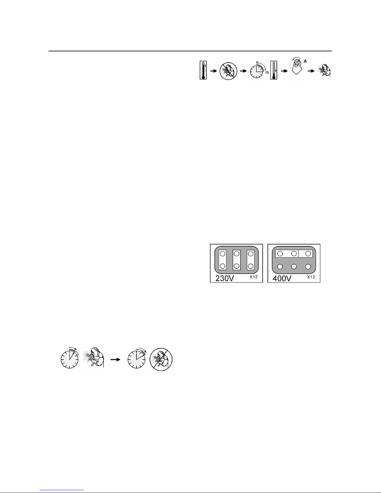
If it is necessary to change the main supply voltage:
• Ensure that the input cable must be disconnected
from the main supply and the machine switched
OFF.
• Remove the top panel from the machine.
• Reconnect X12 according to the diagram below.
• Replace the top panel.
Make sure the amount of power available from the input
connection is adequate for normal operation of the
machine. The necessary delayed fuse (or circuit breaker
with ”D” characteristic) and cable sizes are indicated in
the technical specification section of this manual.
Refer to points 1, 3, 12 and 13 of the images below.
Output Connections
Refer to points 5, 10 and 11 of the images below.
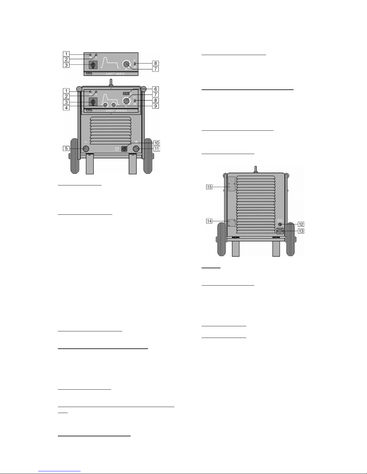
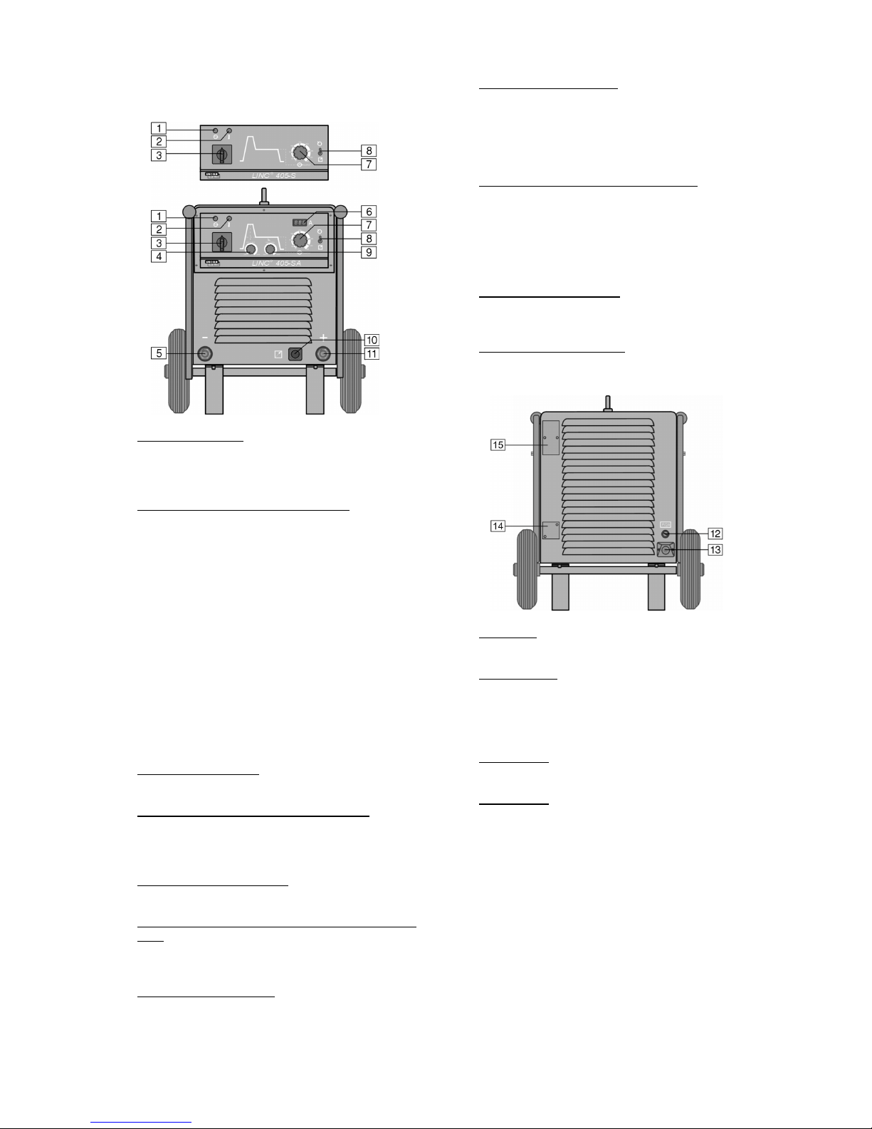
Controls and Operational Features
1. Power Indicator: After input power is connected and
the power switch is turned on, this lamp will light up
to indicate the machine is ready to weld.
2. Thermal Overload Indicator: This lamp will light up
when the machine is overheated and the output has
A
-3
been turned off. This can occur if the ambient
temperature is above 40°C or the duty cycle of the
machine has been exceeded. Leave the machine
on to allow the internal components to cool, when
the lamp turns off normal operation is possible.
• Thermostatic fan: the fan is additionally
controlled by the thermal protection circuit.
This feature saves energy and also minimizes
the amount of dirt and other air borne particles
being drawn into the machine.
The fan is operating only while cooling is
needed.
3. Power on/off Switch: Controls the input power to
the machine.
4. Hot Start Control (LINC 405-SA only): Hot Start is a
temporary increase in the output current during the
start of stick (MMA) welding that helps ignite the arc
quickly and reliably. The potentiometer is used to
set the level of the increased current.
5. Negative Quick Disconnect: Negative output
connector for the welding circuit.
6. Digital Welding Current Meter with memory feature
(LINC 405-SA only): Shows present the value of
the welding current during welding; after welding it
continues to display the average welding current.
7. Output Current Control: Potentiometer used to set
the output current (also during welding), from 15A to
400A.
8. Local/Remote Switch: Remote Control Unit
K10095-1-15M and K870 can be used with this
machine. It changes control of the Output Current
from the machine Output Control (point 7) to the
K10095-1-15M or K870 and vice versa.
9. Arc Force Control (LINC 405-SA only): It is a
function used during stick (MMA) welding in which
the output current is temporarily increased to clear
short circuit connections between the electrode and
the weld puddle that occur during normal welding.
10. Remote Control Connection: If a remote control is
used, it will be connected to the remote connector.
11. Positive Quick Disconnect: Positive output
connector for the welding circuit.
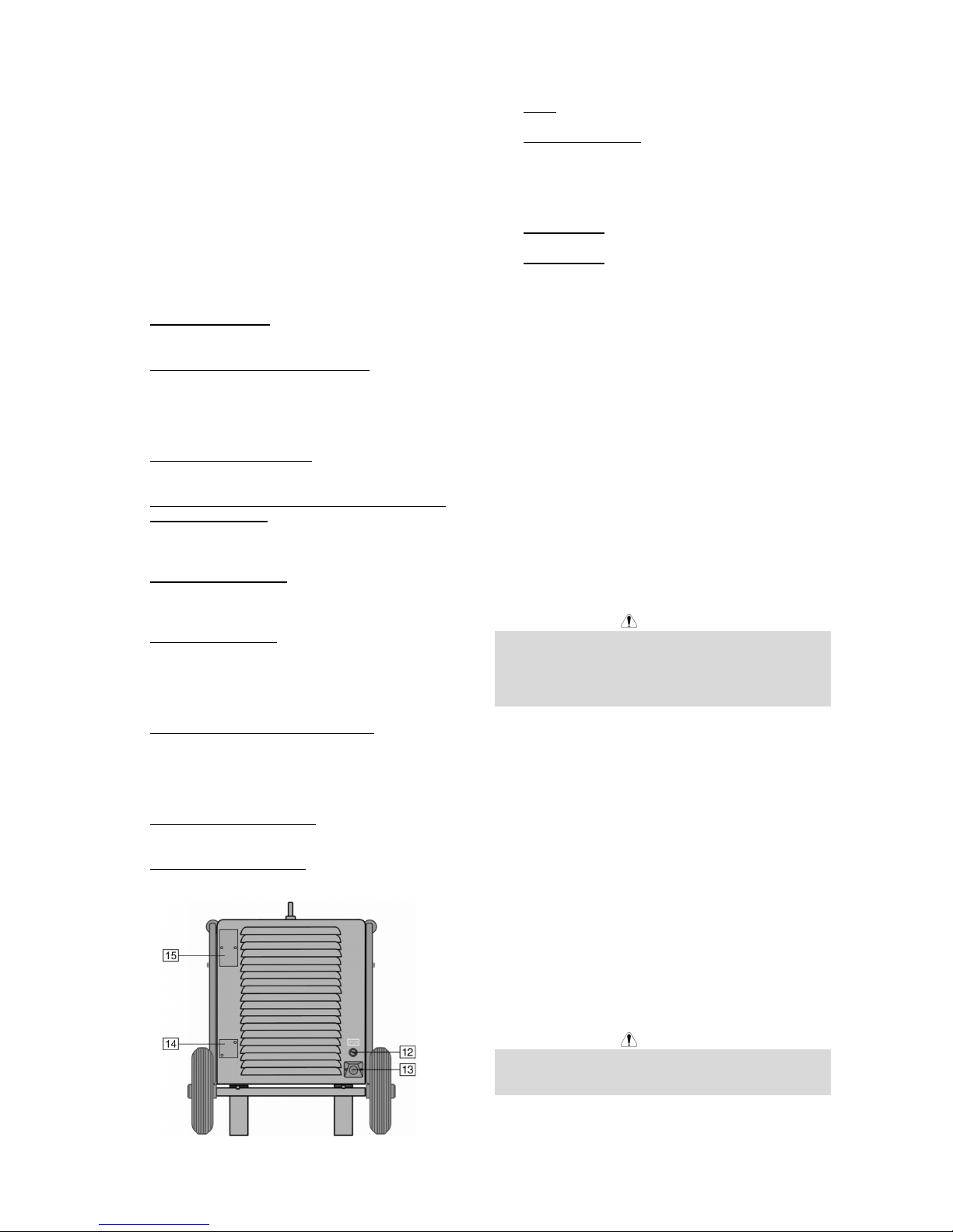
12. Fuse: This fuse protects the Fan Circuit.
13. Power Input Socket: Connect the supply plug to the
existing input cable, that is rated for the machine as
indicated in this manual, and conforms to all
applicable standards. This connection shall be
performed only by a qualified person.
14. Hole covered: For 48Vac socket K14027-1.
15. Hole covered: For circuit breaker which protects the
48Vac socket K14027-1.
Stick Welding (MMA)
For starting welding process with MMA method you
should:
• Insert welding cable plugs into output sockets and
twist to lock them in place.
• Connect the work cable to the welding piece with
the work clamp.
• Fasten a correct coated electrode into the electrode
holder.
• Connect the main plug to the outlet mains socket.
• Set the Local/Remote Switch in required position:
local or remote.
• Turn the Power on/off Switch on.
• Set required welding current by knob of the Output
Current Control.
• Obeying appropriate rules you can begin to weld.
Maintenance
WARNING
For any maintenance or repair operations it is
recommended to contact the nearest technical service
center or Lincoln Electric. Maintenance or repairs
performed by unauthorized service centers or personnel
will null and void the manufacturers warranty.
The frequency of the minatenance operations may vary
in accordance with the working environment where the
machine is placed.
Any noticeable damage should be reported immediately.
Routine maintenance (everyday)
• Check cables and connections integrity. Replace, if
necessary.
• Check condition and operation of the cooling fan.
Keep clean its airflow slots.
Periodic maintenance (every 200 working hours
but not more rarely than once a year)
Perform the routine maintenance and, in addition:
• Keep clean the machine. Using a dry ( and low
pressure) airflow, remove the dust from the external
case and from inside of the cabinet.
• Check and tighten all screws.
WARNING
Mains supply network must be disconnected from the
machine before each maintenance and service. After
each repair, perform proper tests to ensure safety.
A
-4
Electromagnetic Compatibility (EMC)
11/04
This machine has been designed in accordance with all relevant directives and standards. However, it may still generate
electromagnetic disturbances that can affect other systems like telecommunications (telephone, radio, and television) or
other safety systems. These disturbances can cause safety problems in the affected systems. Read and understand
this section to eliminate or reduce the amount of electromagnetic disturbance generated by this machine.
This machine has been designed to operate in an industrial area. To operate in a domestic area it is
necessary to observe particular precautions to eliminate possible electromagnetic disturbances. The
operator must install and operate this equipment as described in this manual. If any electromagnetic
disturbances are detected the operator must put in place corrective actions to eliminate these disturbances
with, if necessary, assistance from Lincoln Electric.
Before installing the machine, the operator must check the work area for any devices that may malfunction because of
electromagnetic disturbances. Consider the following.
• Input and output cables, control cables, and telephone cables that are in or adjacent to the work area and the
machine.
• Radio and/or television transmitters and receivers. Computers or computer controlled equipment.
• Safety and control equipment for industrial processes. Equipment for calibration and measurement.
• Personal medical devices like pacemakers and hearing aids.
• Check the electromagnetic immunity for equipment operating in or near the work area. The operator must be sure
that all equipment in the area is compatible. This may require additional protection measures.
• The dimensions of the work area to consider will depend on the construction of the area and other activities that are
taking place.
Consider the following guidelines to reduce electromagnetic emissions from the machine.
• Connect the machine to the input supply according to this manual. If disturbances occur if may be necessary to take
additional precautions such as filtering the input supply.
• The output cables should be kept as short as possible and should be positioned together. If possible connect the
work piece to ground in order to reduce the electromagnetic emissions. The operator must check that connecting
the work piece to ground does not cause problems or unsafe operating conditions for personnel and equipment.
• Shielding of cables in the work area can reduce electromagnetic emissions. This may be necessary for special
applications.
Technical Specifications
INPUT
Input Voltage
230 / 400V ± 10%
Three Phase
Input Power at Rated Output
34 kVA @ 35% Duty Cycle
Frequency
50 Hertz (Hz)
RATED OUTPUT AT 40°C
Duty Cycle
(Based on a 10 min. period)
35%
60%
100%
Output Current
400A
315A
240A
Output Voltage
36.0 Vdc
33.0 Vdc
29.0 Vdc
OUTPUT RANGE
Welding Current Range
15 – 400 Amps
Maximum Open Circuit Voltage
78 Vdc
RECOMMENDED INPUT CABLE AND FUSE SIZES
Fuse or Circuit Breaker Size
63A Superlag (230V input)
40A Superlag (400V input)
Input Power Cable
4 Conductor, 6 mm
2
PHYSICAL DIMENSIONS
Height
640 mm
Width
580 mm
Length
1150 mm
(700 mm without handles)
Weight
126 Kg
Operating Temperature
–10°C to +40°C
Storage Temperature
-25°C to +55°C
B-1
Sicurezza
11/04
AVVERTENZA
Questa macchina deve essere impiegata solo da personale qualificato. Assicuratevi che tutte le procedure di
installazione, impiego, manutenzione e riparazione vengano eseguite solamente da persone qualificate. Leggere e
comprendere questo manuale prima di mettere in funzione la macchina. La mancata osservanza delle istruzioni di
questo manuale può provocare seri infortuni, anche mortali, alle persone, o danni alla macchina. Leggere e
comprendere le spiegazioni seguenti sui simboli di avvertenza. La Lincoln Electric non si assume alcuna responsabilità
per danni conseguenti a installazione non corretta, incuria o impiego in modo anormale.
AVVERTENZA: Questo simbolo indica che occorre seguire le istruzioni per evitare seri infortuni,
anche mortali, alle persone o danni a questa macchina. Proteggete voi stessi e gli altri dalla
possibilità di seri infortuni anche mortali.
LEGGERE E COMPRENDERE LE ISTRUZIONI: Leggere e comprendere questo manuale prima di
far funzionare la macchina. La saldatura ad arco può presentare dei rischi. La mancata osservanza
delle istruzioni di questo manuale può provocare seri infortuni, anche mortali, alle persone o danni alla
macchina.
LA FOLGORAZIONE ELETTRICA E’ MORTALE: Le macchine per saldatura generano tensioni
elevate. Non toccate l’elettrodo, il morsetto di massa o pezzi da saldare collegati alla macchina
quando la macchina è accesa. Mantenetevi isolati elettricamente da elettrodo, morsetto e pezzi
collegati a questo.
MACCHINA CON ALIMENTAZIONE ELETTRICA: Togliere l’alimentazione con l’interruttore ai fusibili
prima di svolgere operazioni su questa macchina. Mettere la macchina a terra secondo le normative
vigenti.
MACCHINA CON ALIMENTAZIONE ELETTRICA: Ispezionare periodicamente i cavi di
alimentazione, all’elettrodo e al pezzo. Se si riscontrano danni all’isolamento sostituire
immediatamente il cavo. Non posare la pinza portaelettrodo direttamente sul banco di saldatura o
qualsiasi altra superficie in contatto con il morsetto di massa per evitare un innesco involontario
dell’arco.
I CAMPI ELETTRICI E MAGNETICI POSSONO ESSERE PERICOLOSI: Il passaggio di corrente
elettrica in un conduttore produce campi elettromagnetici. Questi campi possono interferire con alcuni
cardiostimolatori (“pacemaker”) e i saldatori con un cardiostimolatore devono consultare il loro medico
su possibili rischi prima di impiegare questa macchina.
CONFORMITÀ CE: Questa macchina è conforme alle Direttive Europee.
FUMI E GAS POSSONO ESSERE PERICOLOSI: La saldatura può produrre fumi e gas dannosi alla
salute. Evitate di respirare questi fumi e gas. Per evitare il pericolo l’operatore deve disporre di una
ventilazione o di un'estrazione di fumi e gas che li allontanino dalla zona in cui respira.
I RAGGI EMESSI DALL’ARCO BRUCIANO: Usate una maschera con schermatura adatta a
proteggervi gli occhi da spruzzi e raggi emessi dall’arco mentre saldate o osservate la saldatura.
Indossare indumenti adatti in materiale resistente alla fiamma per proteggere il corpo, sia vostro che
dei vostri aiutanti. Le persone che si trovano nelle vicinanze devono essere protette da schermature
adatte, non infiammabili, e devono essere avvertite di non guardare l’arco e di non esporvisi.
GLI SPRUZZI DI SALDATURA POSSONO PROVOCARE INCENDI O ESPLOSIONI: Allontanare
dall'area di saldatura quanto può prendere fuoco e tenere a portata di mano un estintore. Gli spruzzi
o altri materiali ad alta temperatura prodotti dalla saldatura attraversano con facilità eventuali piccole
aperture raggiungendo le zone vicine. Non saldare su serbatoi, bidoni, contenitori o altri materiali fino
a che non si sia fatto tutto il necessario per assicurarsi dell'assenza di vapori infiammabili o nocivi.
Non impiegare mai questa macchina se vi è presenza di gas e/o vapori infiammabili o combustibili
liquidi.
I MATERIALI SALDATI BRUCIANO: Il processo di saldatura produce moltissimo calore. Ci si può
bruciare in modo grave con le superfici e materiali caldi della zona di saldatura. Impiegare guanti e
pinze per toccare o muovere materiali nella zona di saldatura.
B-2
MARCHIO DI SICUREZZA: Questa macchina è adatta a fornire energia per operazioni di saldatura
svolte in ambienti con alto rischio di folgorazione elettrica.
Installazione e Istruzioni Operative
Leggere tutta questa sezione prima di installare e
impiegare la macchina.
Collocazione e ambiente
Questa macchina è in grado di funzionare in ambienti
difficili. E’ comunque importante seguire delle semplici
misure di prevenzione per garantirne una lunga durata e
un funzionamento affidabile.
• Non collocare o impiegare la macchina su superfici
inclinate più di 15° rispetto all’orizzontale.
• Non usare questa macchina per sgelare tubi.
• La macchina va collocata ove vi sia una circolazione
di aria pulita senza impedimenti al suo movimento in
entrata e uscita dalle feritoie. Non coprire la
macchina con fogli di carta, panni o stracci quando
è accesa.
• Tenere al minimo polvere e sporco che possano
entrare nella macchina.
• Questa macchina ha una protezione di grado IP23.
Tenetela più asciutta possibile e non posatela su
suolo bagnato o dentro pozzanghere.
• Disponete la macchina lontana da macchinari
controllati via radio. Il suo funzionamento normale
può interferire negativamente sul funzionamento di
macchine controllate via radio poste nelle vicinanze,
con conseguenze di infortuni o danni materiali.
Leggete la sezione sulla compatibilità
elettromagnetica di questo manuale.
• Non impiegate la macchina in zone ove la
temperatura ambiente supera i 40°C.
Fattore di Intermittenza e
Surriscaldamento
Il fattore di intermittenza della saldatrice è la percentuale
di tempo su un periodo di 10 minuti dove è possibile
saldare alla corrente nominale di saldatura (vedi sezione
"Specifiche Tecniche").
Fattore di intermittenza 60%:
saldatura per 6 minuti interruzione per 4 minuti
Un prolungamento eccessivo del fattore di intermittenza
può causare l'intervento del circuito di protezione
termica.
La saldatrice è protetta contro l'eccessivo
surriscaldamento da un termostato. Quando la
macchina è surriscaldata l’erogazione di corrente per la
saldatura è disattivata e la spia che indica la protezione
termica sul cruscotto frontale della saldatrice è accesa.
Quando la macchina si è opportunamente raffreddata la
spia “protezione termica” si spegne e la saldatrice
riprende a lavorare normalmente.
minuti o ridurre il
fattore di
intermittenza
Collegamento all’alimentazione
L'installazione e la connessione all'alimentazione deve
essere eseguita e protetta in accordo con le regole
dedicate.
Prima di accendere la macchina controllate tensione,
fase e frequenza di alimentazione. Verificate il
collegamento del cavo di terra fra macchina e fonte di
alimentazione. Le tensioni di alimentazione ammesse
sono 3x230V e 3x400V 50Hz (400V: impostazione di
fabbrica). Per maggiori informazioni sui dati di
alimentazione fare riferimento alla sezione “Specifiche
tecniche” di questo manuale e sulla targa della
macchina.
Se è necessario cambiare la tensione di alimentazione:
• Assicurarsi che il cavo di alimentazione sia
disconnesso dalla rete e che l’interruttore di
accensione della macchina sia posizionato su
“spento” (OFF).
• Rimuovere il pannello superiore della macchina.
• Riconnettere X12 seguendo la figura sotto.
• Riposizionare il pannello superiore.
Assicuratevi che l’alimentazione fornisca una potenza
sufficiente per il funzionamento normale della macchina.
Nella sezione “Specifiche tecniche” di questo manuale
sono indicate le dimensioni necessarie per i fusibili
ritardati (o interruttori automatici con caratteristica tipo
"D") e cavi.
Riferirsi ai punti 1, 3, 12 e 13 delle immagini sotto.
Collegamenti in uscita
Riferirsi ai punti 5, 10 e 11 delle immagini sotto.
B-3
Comandi e possibilità operative
1. Spia di accensione: Dopo la connessione
all'alimentazione e con l'interruttore principale
posizionato su ON, questa spia si accende per
indicare che la macchina è pronta a saldare.
2. Spia protezione termica: Questa spia si accende
quando la macchina è surriscaldata e il circuito di
saldatura è disattivato. Questo può accadere
quando la temperatura ambiente è sopra 40°C o
quando si eccede con il fattore di intermittenza.
Lasciare la macchina accesa per permettere il
raffreddamento della componentistica interna,
quando la spia si spegne le normali operazioni sono
nuovamente possibili.
• Ventilatore controllato da termostato: Il
ventilatore è addizionalmente controllato dal
circuito di protezione termica. Questa
caratteristica permette un risparmio di energia e
contemporaneamente riduce la quantità di
polvere e sporcizia all'interno della macchina.
Il ventilatore è operativo solo quando il raffreddamento è
richiesto.
3. Interruttore Acceso / Spento: Controlla l'accensione
e lo spegnimento della macchina.
4. Comando Hot Start (solo LINC 405-SA): Hot Start è
un temporaneo incremento della corrente d'uscita
alla partenza della saldatura in stick (MMA); questo
incremento permette un arco rapido ed affidabile.
Tramite il potenziometro è possibile regolare il livello
di Hot Start.
5. Presa Rapida Negativa: Connessione rapida per
cavi di saldatura; polo negativo.
6. Amperometro Digitale con Memoria (solo LINC 405SA): Indica la corrente di saldatura durante la
saldatura. Dopo la saldatura continua a indicare il
valor medio della corrente erogata.
7. Comando Corrente di Saldatura: Questo
potenziometro regola la corrente (anche durante la
saldatura), da 15A a 400A.
8. Interruttore Locale / Remoto: Una unità di controllo
remoto K10095-1-15M o K870 può essere utilizzata
con questa macchina. Questo interruttore sposta la
gestione della corrente di saldatura (punto 7)
all’unità di controllo remoto e viceversa.
9. Comando Arc Force (solo LINC 405-SA): E' una
funzione utilizzata durante la saldatura ad elettrodo
(MMA); la corrente di saldatura viene
temporaneamente incrementata per prevenire
l'incollatura dell'elettrodo sul pezzo durante il
normale processo di saldatura.
10. Connessione Controllo Remoto: Se è usato un
controllo remoto, deve essere connesso a questo
connettore.
11. Presa Rapida Positiva: Connessione rapida per
cavi di saldatura; polo positivo.
12. Fusibile: Questo fusibile protegge il circuito del
ventilatore.
13. Presa di alimentazione: Connettere la spina al cavo
di alimentazione che è dimensionato per le
caratteristiche della macchina indicate in questo
manuale, conformemente alle normative vigenti. Il
collegamento deve essere eseguito solo da
personale che abbia gli appositi requisiti.
14. Foro con coperchio: Per presa 48Vac K14027-1.
15. Foro con coperchio: Per l' interruttore che protegge
la presa 48Vac K14027-1.
Saldatura ad elettrodo (MMA)
Per saldare ad elettrodo (MMA) è necessario:
• Inserire e ruotare le spine dei cavi di saldatura per
bloccarle nelle apposite prese.
• Connettere il cavo massa al pezzo da saldare con
l'apposita pinza.
• Inserire un corretto elettrodo rivestito nella pinza
porta-elettrodo.
• Collegare la spina di alimentazione alla sorgente di
alimentazione.
• Posizionare l'interruttore Locale / Remoto nella
posizione richiesta: Locale o Remoto.
• Accendere la macchina, mediante l'interruttore di
alimentazione.
B-4
• Impostare la corrente di saldatura richiesta
utilizzando il Comando Corrente di Saldatura.
• Rispettare le regole appropriate prima di iniziare a
saldare.
Manutenzione
AVVERTENZA
Per ogni operazione di manutenzione o riparazione si
raccomanda di rivolgersi al più vicino centro di
assistenza tecnica della Lincoln Electric. Manutenzioni o
riparazioni effettuate da personale o centri di servizio
non autorizzati fanno decadere la garanzia del
fabbricante.
La frequenza delle operazioni di manutenzione può
essere variata in funzione dell’ambiente in cui la
macchina si trova a lavorare.
Qualsiasi danno venga notato va immediatamente
riferito a chi di dovere.
Manutenzione corrente (quotidiana)
• Controllare che cavi e collegamenti siano integri.
Sostituirli, se necessario.
• Controllare stato e funzionamento del ventilatore di
raffreddamento. Mantenerne pulite le feritoie.
Manutenzione periodica (ogni 200 ore di lavoro,
ma non meno di una volta all’anno)
Eseguire la manutenzione corrente e, in aggiunta:
• Pulire la macchina. Usare un getto d’aria asciutto e
a bassa pressione per rimuovere la polvere
dall’involucro esterno e dall’interno.
• Controllare e ristringere tutte le viti.
AVVERTENZA
Prima di svolgere qualsiasi operazione di manutenzione
e servizio staccare la macchina dalla rete di
alimentazione. Dopo ogni riparazione, eseguire le prove
necessarie ad assicurare la sicurezza.
Compatibilità Elettromagnetica (EMC)
11/04
Questa macchina è stata progettata nel rispetto di tutte le direttive e normative in materia. Tuttavia può generare dei
disturbi elettromagnetici che possono interferire con altri sistemi come le telecomunicazioni (telefono, radio o televisione)
o altri sistemi di sicurezza. I disturbi possono provocare problemi nella sicurezza dei sistemi interessati. Leggete e
comprendete questa sezione per eliminare o ridurre il livello dei disturbi elettromagnetici generati da questa macchina.
La macchina è stata progettata per funzionare in ambienti di tipo industriale. Il suo impiego in ambienti
domestici richiede particolari precauzioni per l’eliminazione dei possibili disturbi elettromagnetici.
L’operatore deve installare e impiegare la macchina come precisato in questo manuale. Se si riscontrano
disturbi elettromagnetici l’operatore deve porre in atto azioni correttive per eliminarli, avvalendosi, se
necessario, dell’assistenza della Lincoln Electric.
Prima di installare la macchina, controllate se nell’area di lavoro vi sono dispositivi il cui funzionamento potrebbe risultare
difettoso a causa di disturbi elettromagnetici. Prendete in considerazione i seguenti:
• Cavi di entrata o di uscita, cavi di controllo e cavi telefonici collocati nell’area di lavoro, presso la macchina o nelle
adiacenze di questa.
• Trasmettitori e/o ricevitori radio o televisivi. Computers o attrezzature controllate da computer.
• Impianti di sicurezza e controllo per processi industriali. Attrezzature di taratura e misurazione.
• Dispositivi medici individuali come cardiostimolatori (pacemakers) o apparecchi acustici.
• Verificare che macchine e attrezzature funzionanti nell’area di lavoro o nelle vicinanze siano immuni da possibili
disturbi elettromagnetici. L’operatore deve accertare che tutte le attrezzature e dispositivi nell’area siano compatibili.
A questo scopo può essere necessario disporre misure di protezione aggiuntive.
• L’ampiezza dell’area di lavoro da prendere in considerazione dipende dalla struttura dell’area e dalle altre attività
che vi si svolgono.
Per ridurre le emissioni elettromagnetiche della macchina tenete presenti le seguenti linee guida.
• Collegare la macchina alla fonte di alimentazione come indicato da questo manuale. Se vi sono disturbi, può essere
necessario prendere altre precauzioni, come un filtro sull’alimentazione.
• I cavi in uscita vanno tenuti più corti possibile e l’uno accanto all’altro. Se possibile mettere a terra il pezzo per
ridurre le emissioni elettromagnetiche. L’operatore deve controllare che questa messa a terra non provochi
problemi o pericoli alla sicurezza del personale e della macchina e attrezzature.
• Si possono ridurre le emissioni elettromagnetiche schermando i cavi nell’area di lavoro. Per impieghi particolari
questo può diventare necessario.

B-5
Specifiche Tecniche
ALIMENTAZIONE
Tensione di alimentazione
230 / 400V ± 10%
Trifase
Potenza assorbita per uscita nominale
34 kVA per fattore di intermittenza 35%
Frequenza
50 Hz
USCITA NOMINALE a 40°C
Fattore di intermittenza
(su periodo di 10 minuti)
35%
60%
100%
Corrente in uscita
400A
315A
240A
Tensione nominale in uscita
36.0 Vdc
33.0 Vdc
29.0 Vdc
USCITA
Gamma corrente di saldatura
15 – 400 A
Massima tensione a vuoto
78 Vdc
DIMENSIONI RACCOMANDATE PER CAVI E FUSIBILI
Gamma corrente di saldatura
63A Ritardato (alimentazione 230V)
40A Ritardato (alimentazione 400V)
Cavo di alimentazione
4 conduttori da 6 mm
2
DATI FISICI – DIMENSIONI
Altezza
640 mm
Larghezza
580 mm
Lunghezza
1150 mm
(700 mm senza maniglie)
Peso
126 Kg
Temperatura di impiego
–10°C a +40°C
Temperatura di immagazzinamento
-25°C a +55°C

C-1
Sicherheitsmaßnahmen / Unfallschutz
02/05
ACHTUNG
Diese Anlage darf nur von ausgebildetem Fachpersonal genutzt, gewartet und repariert werden. Schließen Sie dieses
Gerät nicht an, arbeiten Sie nicht damit oder reparieren Sie es nicht, bevor Sie diese Betriebsanleitung gelesen und
verstanden haben. Bei Nichtbeachtung der Hinweise kann es zu gefährlichen Verletzungen bis hin zum Tod oder zu
Beschädigungen am Gerät kommen. Beachten Sie auch die folgenden Beschreibungen der Warnhinweise. Lincoln
Electric ist nicht verantwortlich für Fehler, die durch inkorrekte Installation, mangelnde Sorgfalt oder Fehlbenutzung des
Gerätes entstehen.
ACHTUNG: Dieses Symbol gibt an, dass die folgenden Hinweise beachtet werden müssen, um
gefährliche Verletzungen bis hin zum Tode oder Beschädigungen am Gerät zu verhindern. Schützen
Sie sich und andere vor gefährlichen Verletzungen oder dem Tode.
BEACHTEN SIE DIE ANLEITUNG: Lesen Sie diese Anleitung sorgfältig, bevor Sie das Gerät in
Betrieb nehmen. Bei Nichtbeachtung der Hinweise kann es zu gefährlichen Verletzungen bis hin zum
Tod oder zu Beschädigungen am Gerät kommen.
STROMSCHLÄGE KÖNNEN TÖDLICH SEIN: Schweißgeräte erzeugen hohe Stromstärken.
Berühren Sie keine stromführenden Teile oder die Elektrode mit der Haut oder nasser Kleidung.
Schützen Sie beim Schweißen Ihren Körper durch geeignete isolierende Kleidung und Handschuhe.
ELEKTRISCHE GERÄTE: Schalten Sie die Netzspannung am Sicherungskasten aus oder ziehen Sie
den Netzstecker, bevor Arbeiten an der Maschine ausgeführt werden. Erden Sie die Maschine
gemäß den geltenden elektrischen Bestimmungen.
ELEKTRISCHE GERÄTE: Achten Sie regelmäßig darauf, dass Netz-, Werkstück- und
Elektrodenkabel in einwandfreiem Zustand sind und tauschen Sie diese bei Beschädigung aus.
Legen Sie den Elektrodenhalter niemals auf den Schweißarbeitsplatz, damit es zu keinem
ungewollten Lichtbogen kommt.
ELEKTRISCHE UND MAGNETISCHE FELDER BERGEN GEFAHREN: Elektrischer Strom, der
durch ein Kabel fließt, erzeugt ein elektrisches und magnetisches Feld (EMF). EMF Felder können
Herzschrittmacher beeinflussen. Bitte fragen Sie Ihren Arzt, wenn Sie einen Herzschrittmacher
haben, bevor Sie dieses Gerät benutzen.
CE Konformität: Dieses Gerät erfüllt die CE-Normen.
RAUCH UND GASE KÖNNEN GEFÄHRLICH SEIN: Schweißen erzeugt Rauch und Gase, die
gesundheitsschädlich sein können. Vermeiden Sie das Einatmen dieser Metalldämpfe. Benutzen Sie
eine Schweißrauchabsaugung, um die Dämpfe abzusaugen.
LICHTBÖGEN KÖNNEN VERBRENNUNGEN HERVORRUFEN: Tragen Sie geeignete
Schutzkleidung und Schutzmasken für Augen, Ohren und Körper, um sich vor Spritzern und
Strahlungen zu schützen. Warnen Sie auch in der Umgebung befindliche Personen vor den Gefahren
des Lichtbogens. Lassen Sie niemanden ungeschützt den Lichtbogen beobachten.
SCHWEISSPRITZER KÖNNEN FEUER ODER EXPLOSIONEN VERURSACHEN: Entfernen Sie
feuergefährliche Gegenstände vom Schweißplatz und halten Sie einen Feuerlöscher bereit.
Schweißen Sie keine Behälter, die brennbare oder giftige Stoffe enthalten, bis diese vollständig
geleert und gesäubert sind. Schweißen Sie niemals an Orten, an denen brennbare Gase, Stoffe oder
Flüssigkeiten vorhanden sind.
GESCHWEISSTE MATERIALIEN KÖNNEN VERBRENNUNGEN VERURSACHEN: Schweißen
verursacht hohe Temperaturen. Heiße Materialien können somit ernsthafte Verbrennungen
verursachen. Benutzen Sie Handschuhe und Zangen, wenn Sie geschweißte Materialien berühren
oder bewegen.
S-ZEICHEN: Dieses Gerät darf Schweißstrom in Umgebungen mit erhöhter elektrischer Gefährdung
liefern.
C-2
Installation und Bedienungshinweise
Bitte diesen Abschnitt vor Montage und Inbetriebnahme
der Maschine vollständig durchlesen.
Aufstellungsort und -umgebung
Diese Maschine kann auch bei ungünstigen
Umgebungsbedingungen betrieben werden. Jedoch sind
dabei die folgenden Vorsichtsmaßnahmen zu beachten,
um einen sicheren Betrieb und eine lange Lebensdauer
der Maschine zu gewährleisten.
• Die Maschine darf nicht auf einer schrägen Fläche
aufgestellt oder betrieben werden, die eine Neigung
von mehr 15° aufweist.
• Die Maschine darf nicht zum Auftauen von Rohren
verwendet werden.
• Am Aufstellungsort der Maschine ist auf
ausreichende Frischluftzirkulation zu achten. Der
Luftstrom zu den Be- und Entlüftungsöffnungen darf
nicht behindert werden. Die Maschine bei Betrieb
nicht mit Papier, Stoff oder Putzlappen abdecken.
• Schmutz und Staub sind soweit wie möglich von der
Maschine fernzuhalten.
• Die Maschine verfügt über Schutzart IP23 und ist
daher so weit wie möglich trocken zu halten. Sie
darf nicht auf feuchtem oder nassem Untergrund
aufgestellt werden.
• Die Maschine nicht in der Nähe funk- oder
ferngesteuerter Geräte aufstellen. Der
Maschinenbetrieb könnte die Funktion von sich in
der Nähe befindlichen funk- und ferngesteuerten
Geräten so weit beeinflussen, dass Verletzungen
des Bedienpersonals und Schäden an den Geräten
die Folge sein können. Bitte beachten Sie hierzu
auch den Abschnitt bezüglich der
elektromagnetischen Verträglichkeit in dieser
Betriebsanleitung.
• Die Maschine nicht bei Umgebungstemperaturen
von mehr als 40°C in Betrieb nehmen.
Einschaltdauer und Überhitzungsschutz
Die Einschaltdauer ist die Zeit in Prozent von 10 Min.,
bei der mit der eingestellten Stromstärke ununterbrochen geschweißt werden kann.
60% Einschaltdauer:
6 Minuten Schweißen. 4 Minuten Unterbrechung.
Eine Überschreitung der Einschaltdauer aktiviert den
thermischen Schutz.
Das Gerät wird durch einen Thermoschutz vor
Überhitzung geschützt. Bei Überhitzung schaltet es ab
und die thermische Warnleuchte leuchtet auf. Ist das
Gerät abgekühlt, erlischt die Warnleuchte und die
Maschine kann wieder eingeschaltet werden.
Minuten oder
Einschalt-
dauer
verringern
Anschluss an die Stromversorgung
Installation und Stromanschluss müssen vorschriftsmäßig ausgeführt werden.
Überprüfen Sie Netzeingangsspannung, Phase und
Frequenz der Netzversorgung, bevor Sie die Maschine
in Betrieb nehmen. Prüfen Sie die Erdverbindung der
Maschine zum Netzeingang. Die zugelassenen
Eingangsspannungen sind 3x230V und 3x400V, 50Hz
(400V: Herstellereinstellung). Für weitere Informationen
lesen Sie bitte die technischen Daten in dieser
Bedienungsanleitung und das Typenschild der
Maschine.
Bei Änderung der Eingangsspannung:
• Vergewissern Sie sich, daß das Netzkabel von der
Stromquelle abgekoppelt und die Maschine ausgeschaltet ist.
• Entfernen Sie die Abdeckung.
• Verbinden Sie X12 wie im untenstehenden
Diagramm.
• Bringen Sie die Abdeckung wieder an.
Eine ausreichende Spannungs- und Stromversorgung
für den Normalbetrieb der Maschine ist zu
gewährleisten. Die vorzusehende Sicherung (oder
Schutzschalter mit Kenngröße “D”) sowie die
Kabelabmessungen sind in den technischen
Spezifikationen dieser Betriebsanleitung angegeben.
Sh. auch Punkte 1, 3, 12 und 13 der u.a. Abbildungen.
Ausgangsverbindungen
Sh. Punkte 5, 10 und 11 der u.a. Abbildungen.
C-3
Steuerung und Funktion
1. Spannungsanzeige: Nach Anschluss an die
Stromversorgung und nach Einschalten des
Netzschalters leuchtet diese Lampe auf, um die
Betriebsbereitschaft der Maschine anzuzeigen.
2. Thermische Überhitzungs-Warnleuchte: Diese
Leuchte brennt, wenn die Maschine überhitzt ist und
die Ausgangsleistung abgeschaltet ist. Das kann
eintreten, wenn die Umgebungstemperatur 40°C
überschreitet, oder wenn die Einschaltdauer der
Maschine überschritten ist. Lassen Sie das Gerät
eingeschaltet. So können die internen
Komponenten abkühlen. Wenn die Warnleuchte
erlischt, kann das Gerät wieder benutzt werden.
• Thermischer Ventilator: Der Ventilator wird
zusätzlich vom thermischen Schutzkreis
kontrolliert. Dies spart Energie und verringert
die Menge Staub und schwebende Partikel, die
in die Maschine hineingesogen werden.
Der Ventilator ist nur dann eingeschaltet, wenn
Kühlung notwendig ist.
3. Netzschalter EIN/AUS: Steuert die
Stromversorgung zur Maschine.
4. “Heiß-Start”-Steuerung (nur LINC 405-SA ): Der
“Heiß-Start” erhöht für kurze Zeit den Strom beim
Start des Stabelektrodenschweißens (MMA). Der
Stromwert ist einstellbar.
5. Negativschnelltrennschalter: Negativer
Ausgangstrennschalter für den Schweißstromkreis.
6. Digitaler Stromanzeiger mit Speicher (nur LINC 405SA ): Zeigt den aktuellen Stromwert während des
Schweißens. Nach dem Schweißen zeigt er den
Durchschnitts-Stromwert.
7. Schweißstromeinstellung: Mit dem Potentiometer
kann der Schweißstrom von 15 A – 400 A auch
während des Schweißens geregelt werden.
8. Lokal-/Fernregel-Schalter: Die Fernregler K100951-15M und K870 können an diese Maschine
angeschlossen werden. Damit wechselt die
Steuerung (Regelung) des Ausgangs-Stroms von
der Maschine (Punkt 7) zum K10095-1-15M oder
K870 und umgekehrt.
9. Lichtbogensteuerung (nur LINC 405-SA): Diese
Funktion wird während des Stabelektrodenschweißens (MMA) verwendet. Dabei wird der
Ausgangsstrom für kurze Zeit erhöht, um die
Kurzschlussverbindung zwischen Elektrode und
Schweißbad zu trennen, die beim Schweißvorgang
entstehen können.
10. Fernsteuerungsanschluss: Wenn eine
Fernsteuerung verwendet wird, so ist diese an den
Anschluss für die Fernsteuerung anzuschließen.
11. Positivschnelltrennschalter: Positiver
Ausgangsschnelltrennschalter für den
Schweißstromkreis.
12. Sicherung: Diese Sicherung schützt denStromkreis
des Ventilators.
13. Stromeingang: Verbinden Sie die Stromquelle mit
dem Eingangskabel, das für diese Maschine
geeignet ist (in dieser Anleitung angegeben). Diese
Verbindung darf nur von Fachpersonal vorgenommen werden.
14. Blindstopfen: Für 48V WechselstromSteckerbuchse K14027-1.
15. Blindstopfen: Für Stromkreis-Absicherung (48V
Wechselstrom-Steckerbuchse K14027-1).
Stabelektrodenschweißen (MMA)
Vor Start des Stabelektrodenschweißvorgangs (MMA)
sind die folgenden Punkte zu beachten:
• Verbinden Sie die Schweißkabelanschlüsse mit den
Ausgangsanschlüssen und drehen Sie diese, bis sie
fest sitzen.
• Arbeitskabel an Schweißstück mittels
Arbeitsklemme anschließen.
• Eine korrekt umhüllte Elektrode am Elektrodenhalter
befestigen.
• Netzstecker an Stromversorgung anschließen.
• Den Orts-/Fernschalter auf gewünschte Position
schalten: Örtliche oder Fernbetätigung.
• Netzschalter einschalten.
C-4
• Den erforderlichen Schweißstrom mittels
Ausgangsstromsteuerungsregler einstellen.
• Unter Einhaltung der entsprechenden Arbeitsregeln
kann nun mit dem Schweißvorgang begonnen
werden.
Wartung
WARNUNG
Für Wartung und Reparatur des Gerätes konsultieren
Sie bitte Ihren Fachhändler oder die Lincoln Electric.
Eine unsachgemäß durchgeführte Wartung oder
Reparatur durch eine nicht qualifizierte Person führt zum
Erlöschen der Garantie.
Die Wartungsintervalle können abhängig von den
Arbeitsbedingungen der Maschine schwanken.
Ein schwerwiegender Schaden ist unverzüglich zu
melden.
Laufende Wartung (täglich)
• Überprüfen der Kabel und aller Anschlüsse.
Ersetzen Sie diese, wenn erforderlich.
• Überprüfen Sie Zustand und Betrieb des Lüfters –
halten Sie dessen Lüftungsschlitze frei und sauber.
Periodische Wartung (alle 20 Betriebsstunden,
mindestens einmal im Jahr)
Zusätzlich zur laufenden Wartung sind folg. Arbeiten
durchzuführen:
• Halten Sie die Maschine sauber. Verwenden Sie
einen trockenen Luftstrom mit geringem Luftdruck.
Entfernen Sie den Staub von der äußeren Abdeckung und aus dem Innern des Gehäuses.
• Überprüfen Sie alle Schrauben auf festen Sitz und
ziehen Sie diese nach, wenn erforderlich.
WARNUNG
Die Maschine muß während der Durchführung der
Wartungsarbeiten vom Netz getrennt sein. Nach jeder
Reparatur sind geeignete Tests durchzuführen, um die
Betriebssicherheit zu überprüfen.
Elektromagnetische Verträglichkeit (EMC)
11/04
Diese Maschine wurde unter Beachtung aller zugehörigen Normen und Vorschriften gebaut. Dennoch kann es unter
besonderen Umständen zu elektromagnetischen Störungen anderer elektronischer Syteme (z.B. Telefon, Radio, TV,
Computer usw.) kommen. Diese Störungen können im Extremfall zu Sicherheitsproblemen der beeinflussten Systeme
führen. Lesen Sie deshalb diesen Abschnitt aufmerksam durch, um das Auftreten elektromagnetischer Störungen zu
reduzieren oder ganz zu vermeiden.
Diese Maschine ist für den industriellen Einsatz konzipiert worden. Bei Benutzung dieser Anlage in
Wohngebieten sind daher besondere Vorkehrungen zu treffen, um Störungen durch elektromagnetische
Beeinflussungen zu vermeiden. Halten Sie sich stets genau an die in dieser Bedienungsanleitung
genannten Einsatzvorschriften. Falls dennoch elektromagnetische Störungen auftreten, müssen geeignete
Gegenmaßnahmen getroffen werden. Kontaktieren Sie gegebenenfalls den Kundendienst der Lincoln
Electric. Technische Änderungen der Anlage sind nur nach schriftlicher Genehmigung des Herstellers zulässig.
Vergewissern Sie sich vor der Inbetriebnahme des Schweißgerätes, dass sich keine für elektromagnetische Störungen
empfänglichen Geräte und Anlagen im möglichen Einflussbereich befinden. Dies gilt besonders für:
• Steuerleitungen, Datenkabel und Telefonleitungen.
• Radio und Televisions-Sender oder -Empfänger sowie deren Kabelverbindungen. Computer oder
computergesteuerte Anlagen.
• Elektronische Sicherheitseinrichtungen und Steuereinheiten für industrielle Anlagen. Elektronische Mess- und
Kalibriereinrichtungen.
• Medizinische Apparate und Geräte, Hörgeräte oder persönliche Implantate wie Herzschrittmacher usw. Achtung!
Informieren Sie sich vor Inbetriebnahme der Anlage in der Nähe von Kliniken und Krankenhäusern über die hierzu
gültigen Vorschriften, und sorgen Sie für die exakte Einhaltung aller erforderlichen Sicherheitsmaßnahmen!
• Prüfen Sie grundsätzlich die elektromagnetische Verträglichkeit von Geräten, die sich im Einflussbereich der
Schweißanlage befinden.
• Dieser Einflussbereich kann in Abhängigkeit der physikalischen Umstände in seiner räumlichen Ausdehnung stark
variieren.
Befolgen Sie zusätzlich die folgenden Richtlinien um elektromagnetische Abstrahlungen zu reduzieren:
• Schließen Sie die Maschine stets nur wie beschrieben an. Falls dennoch Störungen auftreten, muss eventuell ein
zusätzlicher Netzfilter eingebaut werden.
• Halten Sie die Länge der Schweißkabel möglichst auf ein erforderliches Mindestmaß begrenzt. Wenn möglich,
sollte das Werkstück separat geerdet werden. Beachten Sie stets bei allen Maßnahmen, dass hierdurch keinerlei
Gefährdung von direkt oder indirekt beteiligten Menschen verursacht wird.
• Abgeschirmte Kabel im Arbeitsbereich können die elektromagnetische Abstrahlung reduzieren. Dies kann je nach
Anwendung notwendig sein.
C-5
Technische Daten
Netzeingang
Netzeingangsspannung
230 / 400V ± 10%
Dreiphasig
Leistungsaufnahme
34 kVA @ 35% ED
Frequenz
50 Hertz (Hz)
Leistungsdaten bei 40°C Umgebungstemperatur
Einschaltdauer
(basierend auf 10min-Zyklus)
35%
60%
100%
Ausgangsstromstärke
400 A
315 A
240 A
Ausgangsspannung
36.0 V DC
33.0 V DC
29.0 V DC
Ausgangsleistung
Schweißstrombereich
15 – 400 A
Maximale Leerlaufspannung
78 Vdc
Primärkabelquerschnitte und Absicherung
Sicherung oder Sicherungsautomat
63A träge (230V Eingangsspannung)
40A träge (400V Eingangsspannung)
Primärkabel
4 Adern, 6mm
2
Abmessungen und Gewicht
Höhe
640 mm
Breite
580 mm
Länge
1150 mm
(700 mm ohne Griffe)
Gewicht
126 Kg
Zulässige Umgebungstemperaturen
-10°C bis +40°C
Zulässige Lagerungstemperaturen
-25°C bis +55°C
 Loading...