

Page 1
For use with machines having Code Number : 11075 thru 11293
RETURN TO MAIN MENU
Safety Depends on You
Lincoln arc welding and cutting
equipment is designed and built
with safety in mind. However,
your overall safety can be
increased by proper installation
. . . and thoughtful operation on
your part.
OPERATE OR REPAIR THIS
EQUIPMENT WITHOUT READING THIS MANUAL AND THE
SAFETY PRECAUTIONS CONTAINED THROUGHOUT.
most importantly, think before
you act and be careful.
DO NOT INSTALL,
And,
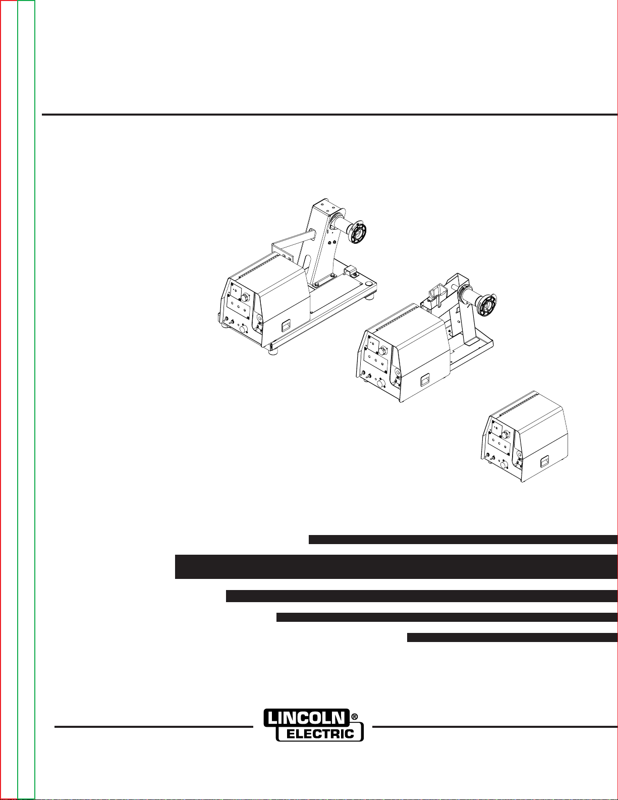
SVM171-A
January, 2007
LF-72/74
View Safety Info View Safety Info View Safety Info View Safety Info
Return to Master TOC Return to Master TOC Return to Master TOC Return to Master TOC
Cleveland, Ohio 44117-1199 U.S.A. TEL: 1-888-935-3877 FAX: 216.486.1751 WEB SITE: www.lincolnelectric.com
SERVICE MANUAL
Copyright © 2007 Lincoln Global Inc.
• World's Leader in Welding and Cutting Products •
• Sales and Service through Subsidiaries and Distributors Worldwide •
Page 2
i
SAFETY
WARNING
CALIFORNIA PROPOSITION 65 WARNINGS
Diesel engine exhaust and some of its constituents
are known to the State of California to cause cancer, birth defects, and other reproductive harm.
The Above For Diesel Engines
ARC WELDING CAN BE HAZARDOUS. PROTECT YOURSELF AND OTHERS FROM POSSIBLE SERIOUS INJURY OR DEATH.
KEEP CHILDREN AWAY. PACEMAKER WEARERS SHOULD CONSULT WITH THEIR DOCTOR BEFORE OPERATING.
Read and understand the following safety highlights. For additional safety information, it is strongly recommended that you
purchase a copy of “Safety in Welding & Cutting - ANSI Standard Z49.1” from the American Welding Society, P.O. Box 351040,
Miami, Florida 33135 or CSA Standard W117.2-1974. A Free copy of “Arc Welding Safety” booklet E205 is available from the
Lincoln Electric Company, 22801 St. Clair Avenue, Cleveland, Ohio 44117-1199.
BE SURE THAT ALL INSTALLATION, OPERATION, MAINTENANCE AND REPAIR PROCEDURES ARE
PERFORMED ONLY BY QUALIFIED INDIVIDUALS.
The engine exhaust from this product contains
chemicals known to the State of California to cause
cancer, birth defects, or other reproductive harm.
The Above For Gasoline Engines
i
FOR ENGINE
powered equipment.
1.a. Turn the engine off before troubleshooting and maintenance
work unless the maintenance work requires it to be running.
____________________________________________________
1.b. Operate engines in open, well-ventilated
areas or vent the engine exhaust fumes
outdoors.
____________________________________________________
1.c. Do not add the fuel near an open flame welding arc or when the engine is running. Stop
the engine and allow it to cool before refueling to prevent spilled fuel from vaporizing on
contact with hot engine parts and igniting. Do
not spill fuel when filling tank. If fuel is spilled,
wipe it up and do not start engine until fumes
have been eliminated.
____________________________________________________
1.d. Keep all equipment safety guards, covers and devices in position and in good repair.Keep hands, hair, clothing and tools
away from V-belts, gears, fans and all other moving parts
when starting, operating or repairing equipment.
____________________________________________________
1.e. In some cases it may be necessary to remove safety
guards to perform required maintenance. Remove
guards only when necessary and replace them when the
maintenance requiring their removal is complete.
Always use the greatest care when working near moving
parts.
___________________________________________________
1.f. Do not put your hands near the engine fan.
Do not attempt to override the governor or
idler by pushing on the throttle control rods
while the engine is running.
1.h. To avoid scalding, do not remove the
radiator pressure cap when the engine is
hot.
ELECTRIC AND
MAGNETIC FIELDS
may be dangerous
2.a. Electric current flowing through any conductor causes
localized Electric and Magnetic Fields (EMF). Welding
current creates EMF fields around welding cables and
welding machines
2.b. EMF fields may interfere with some pacemakers, and
welders having a pacemaker should consult their physician
before welding.
2.c. Exposure to EMF fields in welding may have other health
effects which are now not known.
2.d. All welders should use the following procedures in order to
minimize exposure to EMF fields from the welding circuit:
2.d.1.
Route the electrode and work cables together - Secure
them with tape when possible.
2.d.2. Never coil the electrode lead around your body.
2.d.3. Do not place your body between the electrode and
work cables. If the electrode cable is on your right
side, the work cable should also be on your right side.
2.d.4. Connect the work cable to the workpiece as close as
___________________________________________________
1.g. To prevent accidentally starting gasoline engines while
turning the engine or welding generator during maintenance
work, disconnect the spark plug wires, distributor cap or
magneto wire as appropriate.
Mar ‘95
possible to the area being welded.
2.d.5. Do not work next to welding power source.
Return to Master TOC Return to Master TOC Return to Master TOC Return to Master TOC
Page 3
ii
SAFETY
ii
ELECTRIC SHOCK can kill.
3.a. The electrode and work (or ground) circuits
are electrically “hot” when the welder is on.
Do not touch these “hot” parts with your bare
skin or wet clothing. Wear dry, hole-free
gloves to insulate hands.
3.b. Insulate yourself from work and ground using dry insulation.
Make certain the insulation is large enough to cover your full
area of physical contact with work and ground.
In addition to the normal safety precautions, if welding
must be performed under electrically hazardous
conditions (in damp locations or while wearing wet
clothing; on metal structures such as floors, gratings or
scaffolds; when in cramped positions such as sitting,
kneeling or lying, if there is a high risk of unavoidable or
accidental contact with the workpiece or ground) use
the following equipment:
• Semiautomatic DC Constant Voltage (Wire) Welder.
• DC Manual (Stick) Welder.
• AC Welder with Reduced Voltage Control.
3.c. In semiautomatic or automatic wire welding, the electrode,
electrode reel, welding head, nozzle or semiautomatic
welding gun are also electrically “hot”.
3.d. Always be sure the work cable makes a good electrical
connection with the metal being welded. The connection
should be as close as possible to the area being welded.
3.e. Ground the work or metal to be welded to a good electrical
(earth) ground.
3.f.
Maintain the electrode holder, work clamp, welding cable and
welding machine in good, safe operating condition. Replace
damaged insulation.
3.g. Never dip the electrode in water for cooling.
3.h. Never simultaneously touch electrically “hot” parts of
electrode holders connected to two welders because voltage
between the two can be the total of the open circuit voltage
of both welders.
3.i. When working above floor level, use a safety belt to protect
yourself from a fall should you get a shock.
3.j. Also see Items 6.c. and 8.
ARC RAYS can burn.
4.a. Use a shield with the proper filter and cover
plates to protect your eyes from sparks and
the rays of the arc when welding or observing
open arc welding. Headshield and filter lens
should conform to ANSI Z87. I standards.
4.b. Use suitable clothing made from durable flame-resistant
material to protect your skin and that of your helpers from
the arc rays.
4.c. Protect other nearby personnel with suitable, non-flammable
screening and/or warn them not to watch the arc nor expose
themselves to the arc rays or to hot spatter or metal.
FUMES AND GASES
can be dangerous.
5.a. Welding may produce fumes and gases
hazardous to health. Avoid breathing these
fumes and gases.When welding, keep
your head out of the fume. Use enough
ventilation and/or exhaust at the arc to keep
fumes and gases away from the breathing zone. When
welding with electrodes which require special
ventilation such as stainless or hard facing (see
instructions on container or MSDS) or on lead or
cadmium plated steel and other metals or coatings
which produce highly toxic fumes, keep exposure as
low as possible and below Threshold Limit Values (TLV)
using local exhaust or mechanical ventilation. In
confined spaces or in some circumstances, outdoors, a
respirator may be required. Additional precautions are
also required when welding on galvanized steel.
5. b. The operation of welding fume control equipment is affected
by various factors including proper use and positioning of the
equipment, maintenance of the equipment and the specific
welding procedure and application involved. Worker exposure level should be checked upon installation and periodically thereafter to be certain it is within applicable OSHA PEL
and ACGIH TLV limits.
5.c.
Do not weld in locations near chlorinated hydrocarbon
coming from degreasing, cleaning or spraying operations.
The heat and rays of the arc can react with solvent vapors
form phosgene, a highly toxic gas, and other irritating products.
5.d. Shielding gases used for arc welding can displace air and
cause injury or death. Always use enough ventilation,
especially in confined areas, to insure breathing air is safe.
vapors
to
5.e. Read and understand the manufacturer’s instructions for this
equipment and the consumables to be used, including the
material safety data sheet (MSDS) and follow your
employer’s safety practices. MSDS forms are available from
your welding distributor or from the manufacturer.
5.f. Also see item 1.b.
AUG 06
Return to Master TOC Return to Master TOC Return to Master TOC Return to Master TOC
Page 4
iii
SAFETY
iii
WELDING SPARKS can
cause fire or explosion.
6.a.
Remove fire hazards from the welding area.
If this is not possible, cover them to prevent
the welding sparks from starting a fire.
materials from welding can easily go through small cracks
and openings to adjacent areas. Avoid welding near
hydraulic lines. Have a fire extinguisher readily available.
6.b. Where compressed gases are to be used at the job site,
special precautions should be used to prevent hazardous
situations. Refer to “Safety in Welding and Cutting” (ANSI
Standard Z49.1) and the operating information for the
equipment being used.
6.c. When not welding, make certain no part of the electrode
circuit is touching the work or ground. Accidental contact can
cause overheating and create a fire hazard.
6.d. Do not heat, cut or weld tanks, drums or containers until the
proper steps have been taken to insure that such procedures
will not cause flammable or toxic vapors from substances
inside. They can cause an explosion even
been “cleaned”. For information, purchase “Recommended
Safe Practices for the
Containers and Piping That Have Held Hazardous
Substances”, AWS F4.1 from the American Welding Society
(see address above).
6.e. Vent hollow castings or containers before heating, cutting or
welding. They may explode.
Sparks and spatter are thrown from the welding arc. Wear oil
6.f.
free protective garments such as leather gloves, heavy shirt,
cuffless trousers, high shoes and a cap over your hair. Wear
ear plugs when welding out of position or in confined places.
Always wear safety glasses with side shields when in a
welding area.
6.g. Connect the work cable to the work as close to the welding
area as practical. Work cables connected to the building
framework or other locations away from the welding area
increase the possibility of the welding current passing
through lifting chains, crane cables or other alternate circuits.
This can create fire hazards or overheat lifting chains or
cables until they fail.
6.h. Also see item 1.c.
Remember that welding sparks and hot
though
they have
Preparation
for Welding and Cutting of
CYLINDER may explode
if damaged.
7.a. Use only compressed gas cylinders
containing the correct shielding gas for the
process used and properly operating
regulators designed for the gas and
pressure used. All hoses, fittings, etc. should be suitable for
the application and maintained in good condition.
7.b. Always keep cylinders in an upright position securely
chained to an undercarriage or fixed support.
7.c. Cylinders should be located:
• Away from areas where they may be struck or subjected to
physical damage.
• A safe distance from arc welding or cutting operations and
any other source of heat, sparks, or flame.
7.d. Never allow the electrode, electrode holder or any other
electrically “hot” parts to touch a cylinder.
7.e. Keep your head and face away from the cylinder valve outlet
when opening the cylinder valve.
7.f. Valve protection caps should always be in place and hand
tight except when the cylinder is in use or connected for
use.
7.g. Read and follow the instructions on compressed gas
cylinders, associated equipment, and CGA publication P-l,
“Precautions for Safe Handling of Compressed Gases in
Cylinders,” available from the Compressed Gas Association
1235 Jefferson Davis Highway, Arlington, VA 22202.
FOR ELECTRICALLY
powered equipment.
8.a. Turn off input power using the disconnect
switch at the fuse box before working on
the equipment.
8.b. Install equipment in accordance with the U.S. National
Electrical Code, all local codes and the manufacturer’s
recommendations.
8.c. Ground the equipment in accordance with the U.S. National
Electrical Code and the manufacturer’s recommendations.
Mar ‘95
Return to Master TOC Return to Master TOC Return to Master TOC Return to Master TOC
Page 5

iv
SAFETY
iv
PRÉCAUTIONS DE SÛRETÉ
Pour votre propre protection lire et observer toutes les instructions
et les précautions de sûreté specifiques qui parraissent dans ce
manuel aussi bien que les précautions de sûreté générales suivantes:
Sûreté Pour Soudage A L’Arc
1. Protegez-vous contre la secousse électrique:
a. Les circuits à l’électrode et à la piéce sont sous tension
quand la machine à souder est en marche. Eviter toujours
tout contact entre les parties sous tension et la peau nue
ou les vétements mouillés. Porter des gants secs et sans
trous pour isoler les mains.
b. Faire trés attention de bien s’isoler de la masse quand on
soude dans des endroits humides, ou sur un plancher metallique ou des grilles metalliques, principalement dans
les positions assis ou couché pour lesquelles une grande
partie du corps peut être en contact avec la masse.
c. Maintenir le porte-électrode, la pince de masse, le câble de
soudage et la machine à souder en bon et sûr état defonctionnement.
d.Ne jamais plonger le porte-électrode dans l’eau pour le
refroidir.
e. Ne jamais toucher simultanément les parties sous tension
des porte-électrodes connectés à deux machines à souder
parce que la tension entre les deux pinces peut être le total
de la tension à vide des deux machines.
f. Si on utilise la machine à souder comme une source de
courant pour soudage semi-automatique, ces precautions
pour le porte-électrode s’applicuent aussi au pistolet de
soudage.
zones où l’on pique le laitier.
6. Eloigner les matériaux inflammables ou les recouvrir afin de
prévenir tout risque d’incendie dû aux étincelles.
7. Quand on ne soude pas, poser la pince à une endroit isolé de
la masse. Un court-circuit accidental peut provoquer un
échauffement et un risque d’incendie.
8. S’assurer que la masse est connectée le plus prés possible de
la zone de travail qu’il est pratique de le faire. Si on place la
masse sur la charpente de la construction ou d’autres endroits
éloignés de la zone de travail, on augmente le risque de voir
passer le courant de soudage par les chaines de levage,
câbles de grue, ou autres circuits. Cela peut provoquer des
risques d’incendie ou d’echauffement des chaines et des
câbles jusqu’à ce qu’ils se rompent.
9. Assurer une ventilation suffisante dans la zone de soudage.
Ceci est particuliérement important pour le soudage de tôles
galvanisées plombées, ou cadmiées ou tout autre métal qui
produit des fumeés toxiques.
10. Ne pas souder en présence de vapeurs de chlore provenant
d’opérations de dégraissage, nettoyage ou pistolage. La
chaleur ou les rayons de l’arc peuvent réagir avec les vapeurs
du solvant pour produire du phosgéne (gas fortement toxique)
ou autres produits irritants.
11. Pour obtenir de plus amples renseignements sur la sûreté, voir
le code “Code for safety in welding and cutting” CSA Standard
W 117.2-1974.
2. Dans le cas de travail au dessus du niveau du sol, se protéger
contre les chutes dans le cas ou on recoit un choc. Ne jamais
enrouler le câble-électrode autour de n’importe quelle partie du
corps.
3. Un coup d’arc peut être plus sévère qu’un coup de soliel, donc:
a. Utiliser un bon masque avec un verre filtrant approprié ainsi
qu’un verre blanc afin de se protéger les yeux du rayonnement de l’arc et des projections quand on soude ou
quand on regarde l’arc.
b. Porter des vêtements convenables afin de protéger la peau
de soudeur et des aides contre le rayonnement de l‘arc.
c. Protéger l’autre personnel travaillant à proximité au
soudage à l’aide d’écrans appropriés et non-inflammables.
4. Des gouttes de laitier en fusion sont émises de l’arc de
soudage. Se protéger avec des vêtements de protection libres
de l’huile, tels que les gants en cuir, chemise épaisse, pantalons sans revers, et chaussures montantes.
5. Toujours porter des lunettes de sécurité dans la zone de
soudage. Utiliser des lunettes avec écrans lateraux dans les
PRÉCAUTIONS DE SÛRETÉ POUR
LES MACHINES À SOUDER À
TRANSFORMATEUR ET À
REDRESSEUR
1. Relier à la terre le chassis du poste conformement au code de
l’électricité et aux recommendations du fabricant. Le dispositif
de montage ou la piece à souder doit être branché à une
bonne mise à la terre.
2. Autant que possible, I’installation et l’entretien du poste seront
effectués par un électricien qualifié.
3. Avant de faires des travaux à l’interieur de poste, la debrancher à l’interrupteur à la boite de fusibles.
4. Garder tous les couvercles et dispositifs de sûreté à leur place.
Return to Master TOC Return to Master TOC Return to Master TOC Return to Master TOC
Mar. ‘93
Page 6

MASTER TABLE OF CONTENTS FOR ALL SECTIONS
RETURN TO MAIN MENU
Safety . . . . . . . . . . . . . . . . . . . . . . . . . . . . . . . . . . . . . . . . . . . . . . . . . . . . . . . . i-iv
Installation LF-72 . . . . . . . . . . . . . . . . . . . . . . . . . . . . . . . . . . . . . . . . . . . . . . Section A
Installation LF-74 . . . . . . . . . . . . . . . . . . . . . . . . . . . . . . . . . . . . . . . . . . . . . .Section AA
Operation LF-72 . . . . . . . . . . . . . . . . . . . . . . . . . . . . . . . . . . . . . . . . . . . . . . . Section B
Operation LF-74 . . . . . . . . . . . . . . . . . . . . . . . . . . . . . . . . . . . . . . . . . . . . . . .Section BB
Accessories LF-72 . . . . . . . . . . . . . . . . . . . . . . . . . . . . . . . . . . . . . . . . . . . . . Section C
Accessories LF-74 . . . . . . . . . . . . . . . . . . . . . . . . . . . . . . . . . . . . . . . . . . . . .Section CC
Maintenance LF-72 . . . . . . . . . . . . . . . . . . . . . . . . . . . . . . . . . . . . . . . . . . . . . Section D
Maintenance LF-74 . . . . . . . . . . . . . . . . . . . . . . . . . . . . . . . . . . . . . . . . . . . . .Section DD
Theory of Operation . . . . . . . . . . . . . . . . . . . . . . . . . . . . . . . . . . . . . . . . . . . . Section E
vv
Troubleshooting and Repair . . . . . . . . . . . . . . . . . . . . . . . . . . . . . . . . . . . . . Section F
Electrical Diagrams . . . . . . . . . . . . . . . . . . . . . . . . . . . . . . . . . . . . . . . . . . . . Section G
Parts Manual . . . . . . . . . . . . . . . . . . . . . . . . . . . . . . . . . . . . . . . . . . . . . .P501 Series (LF-72)
P518 Series (LF-74)
LF-72/74
Page 7

Section A-1 Section A-1
TABLE OF CONTENTS
- INSTALLATION SECTION -
Installation ..............................................................................................................Section A
Technical Specifications...............................................................................................A-2
Safety Precautions .......................................................................................................A-3
Location ..................................................................................................................A-3
Mounting .................................................................................................................A-3
Bench Mount ..........................................................................................................A-4
Swivel Mount ..........................................................................................................A-4
Boom Mount ...........................................................................................................A-4
Suspended..............................................................................................................A-4
Weld Cable Sizes....................................................................................................A-5
Coaxial Weld Cables...............................................................................................A-6
Weld Cable Connections ........................................................................................A-6
Analog Control Cable Connections..............................................................................A-7
Analog Miller Control Cable Adapter ...........................................................................A-8
Welding Gun/Wire Feeder Trigger Connector.........................................................A-9
High Frequency Protection.....................................................................................A-9
Remote Sense Lead Specifications........................................................................A-9
Wire Drive Systems ......................................................................................................A-9
Welding Guns, Torches and Accesories ....................................................................A-10
Procedure for Changing Drive and Idle Roll Sets......................................................A-11
Wire Drive Configuration..............................................................................A-11/A-12
Pressure Arm Adjustment.....................................................................................A-12
Wire Reel Loading.................................................................................................A-13
Weld Wire Routing ................................................................................................A-14
Sheilding Gas Connections........................................................................................A-15
Installing Electrode Conduit Kits................................................................................A-16
Aluminum Wire Preperations......................................................................................A-17
Base Model, Bench Model Standard Duty and Bench Model Heavy Duty...............A-18
Typical System Configurations...................................................................................A-19
Return to Master TOC Return to Master TOC Return to Master TOC Return to Master TOC
LF-72/74 SINGLE/DUAL
Page 8
A-2
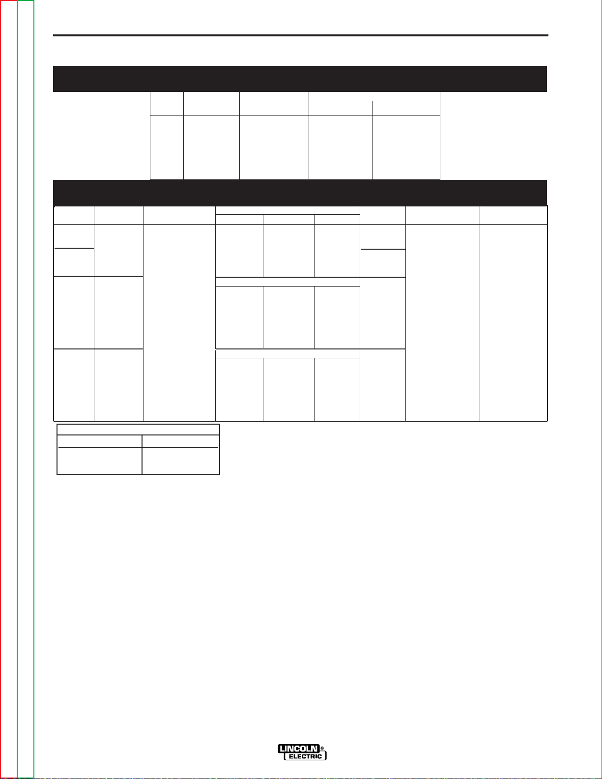
TECHNICAL SPECIFICATIONS
SPEC.# TYPE WIRE FEED SPEED RANGE
LF-72 Speed Solid Cored
INSTALLATION
:
LF-72 Wire Feeder
A-2
Wire Size
K2327-1
K2327-4
K2327-2 Bench Model 50-800 IPM .023 - 1/16 in. .035 - 5/64 in
K2327-3 Bench Mode
SPEC.# TYPE
Input Voltage Dimensions
K2327-1
K2327-4
K2327-2
K2327-3
LF-72 11.1“ 10.2“ 12.9“ (19.7 Kg.)
Base Model
LF-72
Bench 9 AMPS ( 320 mm) (277 mm) (572 mm) (23.8 Kg.) (-10°C to 40°C) (-40°C to 85°C)
Standard
Duty
LF-72
Bench ( 389 mm) (330 mm) (704 mm) (30.6 Kg.)
Heavy
Duty
INPUT POWER
24-42VAC 12.6“ 10.9“ 22.5“ 52.5 Lbs 14°F to 104°F -40°F to 85°F
Base Model
Standard Duty
Heavy Duty
(1.27-20.3 m/m) (0.6 - 1.6 mm) (0.9 - 2.0 mm)
CONTROL BOX, WIRE DRIVE AND COMPLETE UNITS
PHYSICAL SIZE• TEMPERATURE RATING
and Current Height Width Depth Weight Operating Storage
( 282 mm) (259 mm) (328 mm)
Dimensions ∆
Height Width Depth Weight
Dimensions ∆
Height Width Depth Weight
15.3“ 13.0“ 27.7“ 67.5 Lbs
43 Lbs
26.5 Lbs
(12.0 Kg)
WELDING CAPACITY RATING
Amp Rating Duty Cycle
500 A 60%
400 A 100%
∆ Dimensions do not include wire reel.
Return to Master TOC Return to Master TOC Return to Master TOC Return to Master TOC
Return to Section TOC Return to Section TOC Return to Section TOC Return to Section TOC
LF-72/74
Page 9
A-3 A-3
INSTALLATION
SAFETY PRECAUTION
ELECTRIC SHOCK can kill.
• Only qualified personnel should
perform this installation.
• Turn off the input power to the
power source at the disconnect
switch or fuse box before working
on this equipment. Turn off the
input power to any other equipment
connected to the welding system at
the disconnect switch or fuse box
before working on this equipment.
• Do not touch electrically hot parts.
----------------------------------------------------------------------------------------
LOCATION
The LF-72 may be placed on a bench or mounted on
top of a welding power source.
Place the LF-72 in a clean and dry location.
Do not stack the LF-72.
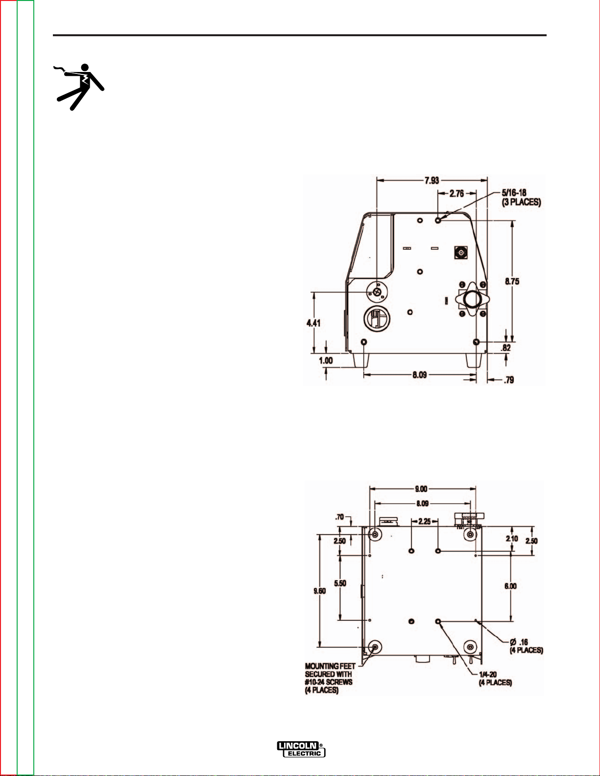
MOUNTING
For location and size,
Mounting Holes (See Figure A.1) and for
Mounting Holes (See Figure A.2).
LF-72 Bench Model Rear
FIGURE A.1
Bottom
FIGURE A.2
Return to Master TOC Return to Master TOC Return to Master TOC Return to Master TOC
Return to Section TOC Return to Section TOC Return to Section TOC Return to Section TOC
LF-72/74
Page 10
A-4 A-4
INSTALLATION
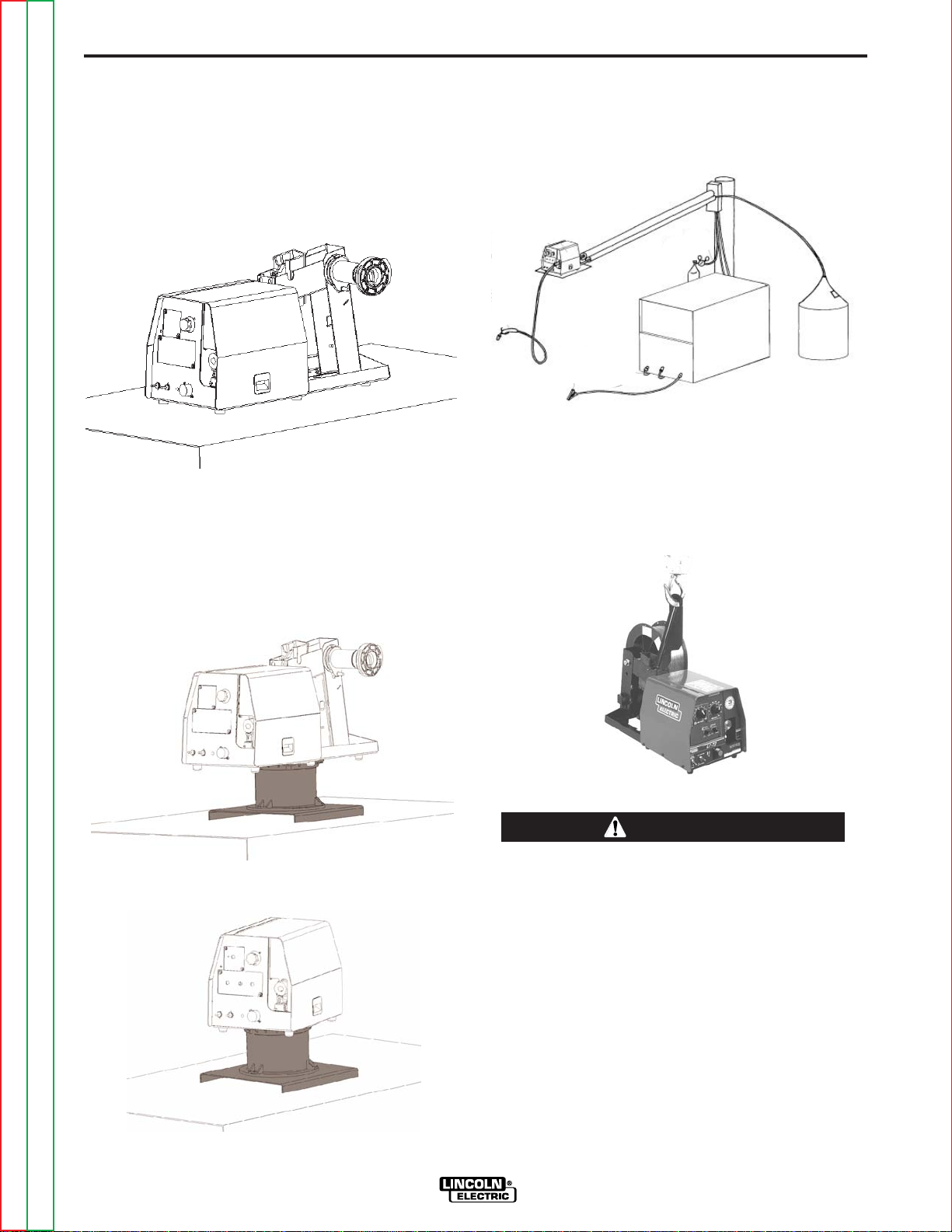
BENCH MOUNT
The LF-72 mounts in a variety of configurations. As
shipped from the factory, the LF-72 is suitable for
bench mounting or placing directly on top of the welding power source (CV-xxx and DC-xxx product family
only).
Bench Mount
SWIVEL MOUNT
Both the standard duty bench model and heavy duty
bench model may be mounted onto a swivel when a
top a welding power source.
BOOM MOUNT
When boom mounting, remove the wire reel stand (if
assembled) and secure the wire feeder directly to the
desired surface.
SUSPENDED
Only suspend the wire feeder by the lift bail of the
portability kit.
Swivel Kit and Bench Model, Standard Duty
Swivel Kit and Base Model LF-72
WARNING
Alternative methods for hanging the wire feeder
must not be used unless insulation is provided
between the wire feeder enclosure and the hanging
device.
------------------------------------------------------------------------
Return to Master TOC Return to Master TOC Return to Master TOC Return to Master TOC
Return to Section TOC Return to Section TOC Return to Section TOC Return to Section TOC
LF-72/74
Page 11

A-5 A-5
INSTALLATION
SAFETY PRECAUTION
ELECTRIC SHOCK can kill.
• Only qualified personnel should
perform this installation.
• Turn off the input power to the
power source at the disconnect
switch or fuse box before working
on this equipment. Turn off the
input power to any other equipment
connected to the welding system at
the disconnect switch or fuse box
before working on this equipment.
• Do not touch electrically hot parts.
----------------------------------------------------------------------
WELD CABLE SIZES
Table A.1 has the copper cable sizes recommended for
different currents and duty cycles. Lengths stipulated
are the distance from the welder to work and back to
the welder again. Cable sizes are increased for
greater lengths primarily for the purpose of minimizing
voltage in the welding circuit.
Amperes
200
200
225
225
250
250
250
250
300
325
350
400
400
500
TABLE A.1
RECOMMENDED CABLE SIZES (RUBBER COVERED COPPER - RATED 75°C)**
CABLE SIZES FOR COMBINED LENGTHS OF ELECTRODE AND WORK CABLES
Percent
Duty
Cycle
60
100
20
40 & 30
30
40
60
100
60
100
60
60
100
60
0 to 50 Ft.
0 to 15 m
2
2
4 or 5
3
3
2
1
1
1
2/0
1/0
2/0
3/0
2/0
50 to 100Ft.
15 to 31 m
2
2
3
3
3
2
1
1
1
2/0
1/0
2/0
3/0
2/0
100 to 150 Ft.
31 to 48 m
2
2
2
2
2
1
1
1
1
2/0
2/0
2/0
3/0
3/0
150 to 200 Ft.
48 to 61 m
1
1
1
1
1
1
1
1
1/0
2/0
2/0
3/0
3/0
3/0
200 to 250 Ft.
61 to 76 m
1/0
1/0
1/0
1/0
1/0
1/0
1/0
1/0
2/0
3/0
3/0
4/0
4/0
4/0
** Tabled values are for operation at ambient temperatures of 40°C and below. Applications above 40°C
may require cables larger than recommended, or cables rated higher than 75°C.
Return to Master TOC Return to Master TOC Return to Master TOC Return to Master TOC
Return to Section TOC Return to Section TOC Return to Section TOC Return to Section TOC
LF-72/74
Page 12
A-6 A-6
El ectrode
Work
Work
Power Source
Work
Electrode
Wire Feeder
Electrode
Work
Coaxial Weld Cable
INSTALLATION
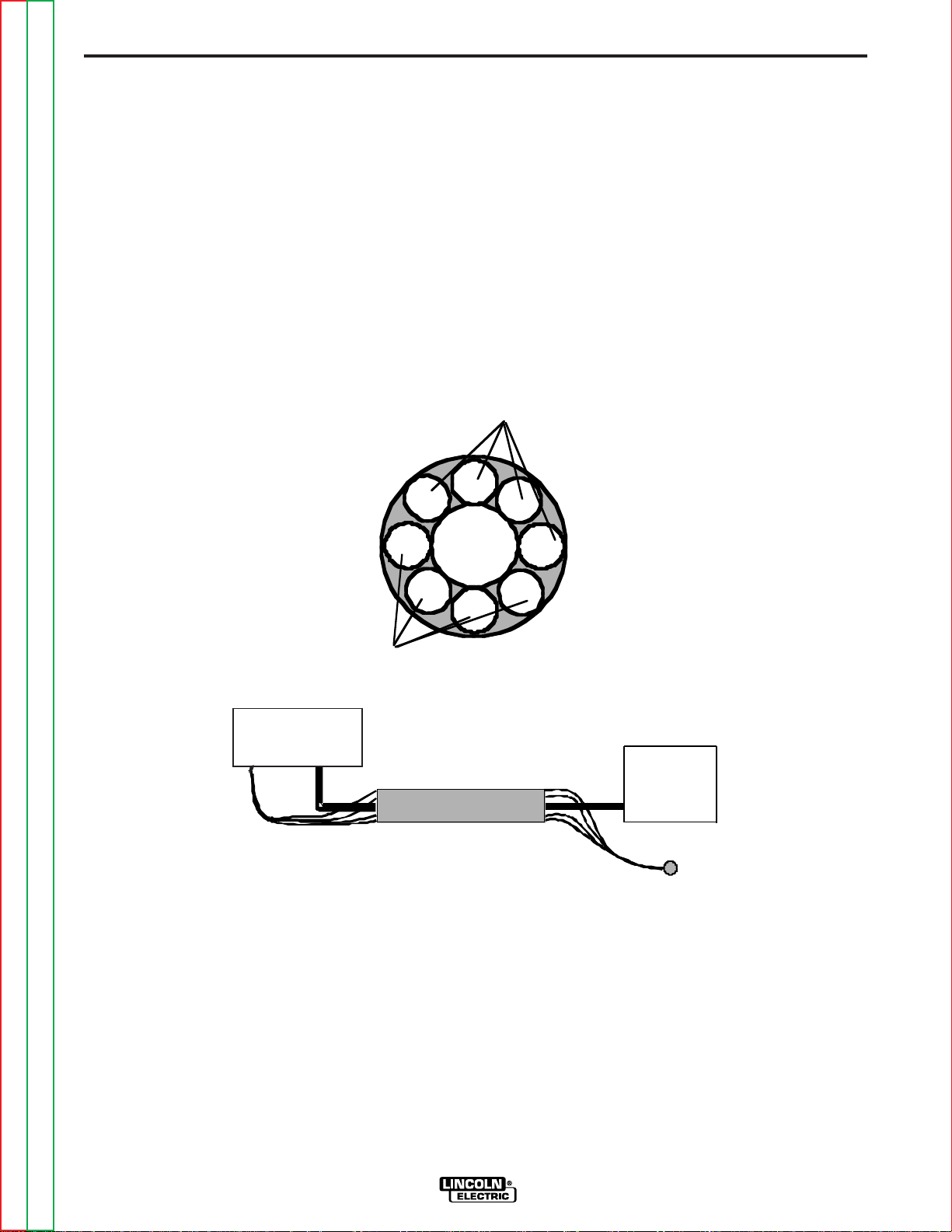
COAXIAL WELD CABLES
Coaxial welding cables are specially designed welding
cables for pulse welding or STT welding. Coaxial weld
cables feature low inductance, allowing fast changes in
the weld current. Regular cables have a higher inductance which may distort the pulse or STT wave shape.
Inductance becomes more severe as the weld cables
become longer.
Coaxial weld cables are recommended for all pulse
and STT welding, especially when the total weld cable
length (electrode cable + work cable) exceeds 50 feet
(7.6m)
A coaxial weld cable is constructed by 8 small leads
wrapped around one large lead. The large inner lead
connects to the electrode stud on the power source
and the electrode connection on the wire feeder. The
small leads combine together to form the work lead,
one end attached to the power source and the other
end to the work piece.
(See Coaxial weld Cable below.)
WELD CABLE CONNECTION
Connect a work lead of sufficient size between the
proper output stud on the power source and the work.
Be sure the connection to the work makes tight metal
to metal electrical contact. Poor work lead connections
can result in poor welding performance.
Return to Master TOC Return to Master TOC Return to Master TOC Return to Master TOC
Return to Section TOC Return to Section TOC Return to Section TOC Return to Section TOC
LF-72/74
Page 13
A-7 A-7
A
I
H
G
B
F
E
D
C
J
K
N
M
L
A
B
C
D
I
E
F
G
H
J
K
L
M
N
POWER SOURCE WIRE FEEDER
INSTALLATION
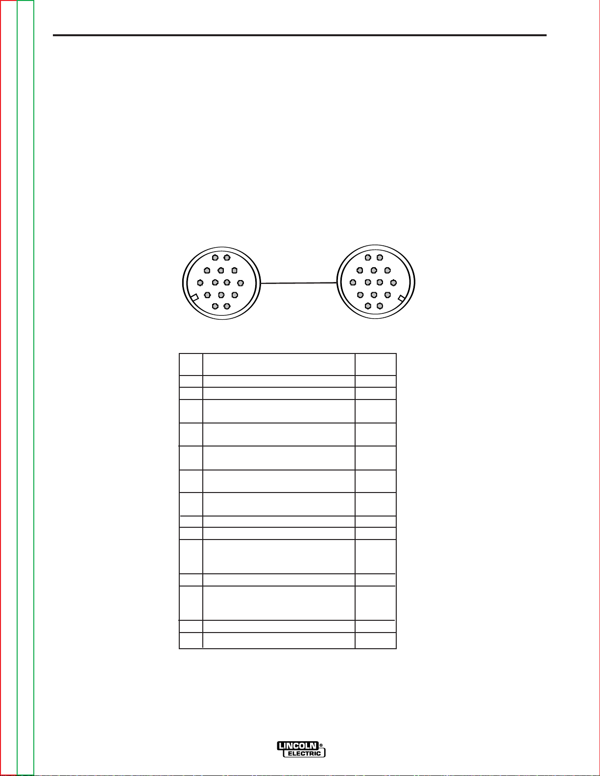
ANALOG CONTROL CABLE
CONTROL CABLE CONNECTIONS
• All control cables can be connected end to end to
extend their length.
The control cable connecting the wire feeder to the
power source is specially made for the welding environment.
The wire feeder power requires overcurrent protection.
Connect the wire feeder only to power sources with
overcurrent protection of no more than 15 amps.
PIN FUNCTION LEAD#
A Unused -------
B Reserved ------C Welding Output Control 2
(trigger from feeder)
D Welding Output Control 4
(trigger from feeder)
E Remote Voltage Control 77
(“+” supply from feeder or remote)
F Remote Voltage Control 76
(control signal from feeder or remote)
G Remote Voltage Control 75
(“-” supply from feeder or remote)
H Reserved
I 42 VAC 41
J Reserve for Future Use.
K 42 VAC 42
L Reserve for Future Use.
M Unused ------N Electrode voltage from feeder 67
Do not use more than 100 ft (30.5 m) of control cable
Return to Master TOC Return to Master TOC Return to Master TOC Return to Master TOC
Return to Section TOC Return to Section TOC Return to Section TOC Return to Section TOC
between the wire feeder and power source.
LF-72/74
Page 14

A-8 A-8
A
B
C
D
I
E
F
G
H
J
K
L
M
N
A
I
H
G
B
F
E
D
C
J
K
N
M
L
W
IRE FEEDERPOWER SOURCE
NOTES
ANALOG MILLER CONTROL CABLE
ADAPTER K2335-1
This Lincoln Electric wire feeder may be mounted to a limited number of Miller Electric power sources. The Miller power
source must have the amphenol pin definition shown in the
table below for proper operation of the wire feeder.
Operation of Lincoln wire feeders on Miller power sources
may result in lack of high speeds or reduce pull force on high
wire feed speeds. Maximum wire feed speed for the LF-72
operating on a Miller power source is approximately 720ipm.
Be sure the Miller power source provides 24 VAC to the wire
feeder and has overcurrent protection of no more than 15
amps. The power source must not exceed 113VDC peak.
MILLER POWER SOURCE
Pin Function
A 24 VAC to feeder
Pin Function
I 42 VAC feeder
LINCOLN WIRE FEEDER
D Welding Output Control
B Welding Output Control
C +10VDC to feeder for remote control
C Welding Output Control
E Remote Voltage Control ("+" supply, from
power source)
D Remote control common
G Remote Voltage Control ("-" supply, from
power source)
E 0-10VDC from feeder for remote control.
F Remote Voltage Control (control signal from
feeder or remote.)
F Current feedback to feeder.
J Reserved for future use.
Scaled 0-10V. 1 V = 100 amps.
Referenced to pin D.
G 24 VAC common.
H Arc Voltage feedback to feeder.
K 42 VAC to feeder
L Reserved for future use.
Scaled 0-10V. 1 V = 10 Arc volts.
Referenced to pin D.
I
J
K
L
M
N
Miller is a registered trademark not owned or licensed by The Lincoln Electric Company.
N Electrode voltage to power source (67)
Return to Master TOC Return to Master TOC Return to Master TOC Return to Master TOC
Return to Section TOC Return to Section TOC Return to Section TOC Return to Section TOC
LF-72/74
Page 15

A-9 A-9
W
elding Gun
W
ire Feeder
A
mphenol
A
B
C
D
E
Trigger Lead
INSTALLATION
WELDING GUN/WIRE FEEDER TRIGGER
CONNECTOR
Wire Feeder
Pin Function
A Gun Trigger
BC Common
DE-
HIGH FREQUENCY PROTECTION
Locate the LF-72 away from radio controlled machinery. The normal operation of the LF-72 may adversely
affect the operation of RF controlled equipment, which
may result in bodily injury or damage to the equipment
REMOTE SENSE LEAD SPECIFICATIONS
Refer to the power source instruction manual for
instructions for connecting the wire feeder for STT
welding.
WIRE DRIVE SYSTEMS
Drive Roll Kits are designed to feed specific types and
wire sizes. The LF-72 Bench Model comes with the
combo
not included, but are available for ordering from the following tables:
Drive Roll Kits, Steel Wires
Includes: 2 Smooth V groove drive rolls and an inner
wire guide.
Drive Roll Kits, Cored Wires
Includes: 2 Knurled drive rolls and an inner wire guide.
KP1696-1. All other Drive Roll Kits listed are
KP1696-030S .023-.030 (0.6-0.8mm)
KP1696-035S .035 (0.9mm)
KP1696-045S .045 (1.2mm)
KP1696-052S .052 (1.4mm)
KP1696-1/16S 1/16 (1.6mm)
KP1696-1 .035, .O45 (0.9, 1.2mm)
KP1696-2 .040 (1.0mm)
KP1697-035C .030-.035" (0.8-0.9mm)
KP1697-045C .040-.045" (1.0-1.2mm)
KP1697-052C .052" (1.4mm)
KP1697-1/16C 1/16" (1.6mm)
KP1697-068 .068-.072" (1.7-1.8mm)
KP1697-5/64C 5/64" (2.0mm)
Drive Roll Kits, Aluminum Wire
Includes: 2 polished U groove drive rolls, outer wire
guide and an inner wire guide.
KP1695-035A .035" (0.9 mm)
KP1695-040A .040" (1.0mm)
KP1695-3/64A 3/64" (1.2mm)
KP1695-1/16A 1/16" (1.6mm)
DRIVE ROLLS
INNER WIRE
GUIDE
Return to Master TOC Return to Master TOC Return to Master TOC Return to Master TOC
Return to Section TOC Return to Section TOC Return to Section TOC Return to Section TOC
LF-72/74
Page 16

A-10 A-10
WIRE DRIVE UNIT
GUN RECEIVER BUSHING
(INTERCHANGABLE)
TRIGGER RECEPTACLE
LF-72 BASE MODEL
GUN TRIGGER
CONNECTOR
CABLE CONNECTOR
END K466-10
GUN NOZZLE
GUN HANDLE
GUN TUBE
GUN AND CABLE
INSTALLATION
WELDING GUNS, TORCHES AND ACCESSORIES
GUN RECEIVER BUSHING
The LF-72 wire feeder comes with a K1500-2 gun
receiver bushing.
MAGNUM GUN AND CABLE ASSEMBLIES
The LF-72 wire feeder model will accept a number of
optional gun and cable assemblies. An example of
installing the Gun and Cable is shown in Figure A.3
with a 15 ft. (4.6m) long Magnum 400 gun and cable.
1. Turn off power at the welding power source.
2. Unscrew Thumb screw on Wire Drive Unit, until tip
of screw no longer protrudes into gun bushing hole
as seen from the front of machine.
FIGURE A.3
3. Fully insert the gun cable connector end into the
gun receiver bushing and gently tighten the thumb
screw as show in Figure A.3 below.
4. Connect the gun trigger connector to the trigger
receptacle. Make sure that the key ways are
aligned and insert.
Return to Master TOC Return to Master TOC Return to Master TOC Return to Master TOC
Return to Section TOC Return to Section TOC Return to Section TOC Return to Section TOC
LF-72/74
Page 17
A-11 A-11
GUN RECEIVER BUSHING
LOOSEN TIGHTEN
THUMB SCREW
OUTER WIRE GUIDE
SOCKET HEAD
CAP SCREW
CONNECTOR BLOCK
INSTALLATION
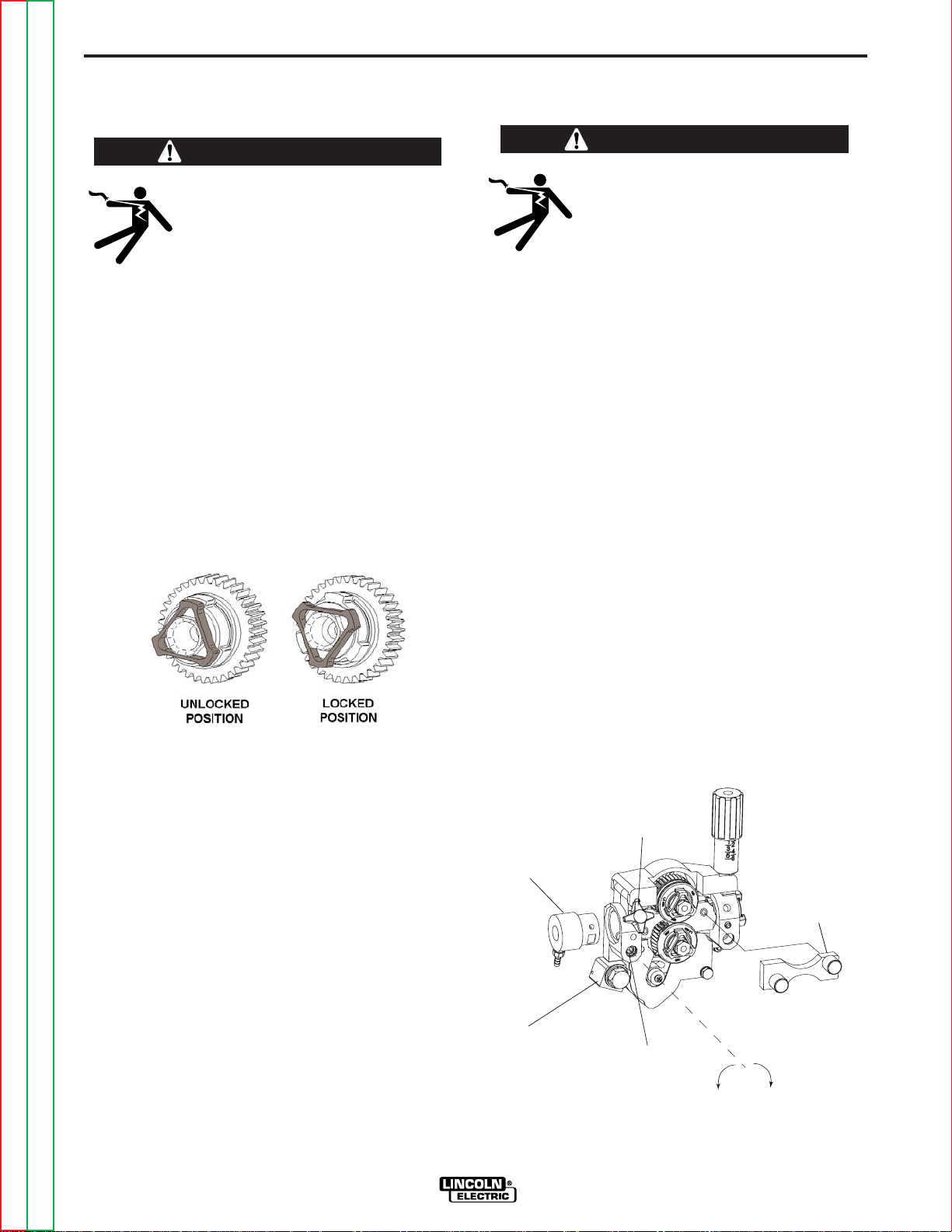
PROCEDURE FOR CHANGING
DRIVE AND IDLE ROLL SETS
(See Figure A.4 )
WARNING
ELECTRIC SHOCK can kill.
• Turn the input power OFF at the
welding power source before installation or changing drive rolls and/or
guides.
• Do not touch electrically live parts.
• When inching with the gun trigger, electrode and
drive mechanism are "hot" to work and ground
and could remain energized several seconds
after the gun trigger is released.
• Only qualified personnel should perform maintenance work.
-----------------------------------------------------------------------
-
1. Turn power off at the welding power source.
2. Release the idle roll pressure arm.
3. Remove the outer wire guide by turning the knurled
thumbscrews counter-clockwise to unscrew them
from the feed plate.
4. Rotate the triangular lock and remove the drive
WIRE DRIVE CONFIGURATION
(See Figure A.5)
Changing the Gun Receiver Bushing
WARNING
ELECTRIC SHOCK can kill.
• Turn the input power OFF at the disconnect switch or fuse box before
attempting to connect or disconnect
input power lines, output cables or
control cables.
• Only qualified personnel should perform this
installation.
------------------------------------------------------------------------
Tools required:
• 1/4" hex key wrench
Note: Some gun bushings do not require the use of
the thumb screw.
1. Turn power off at the welding power source.
2. Remove the welding wire from the wire drive.
3. Remove the thumb screw from the wire drive.
4. Remove the welding gun from the wire drive.
5. Remove the inner wire guide.
6. Insert the new inner wire guide, groove side out,
7. Install a drive roll on each hub assembly secure
8. Install the outer wire guide by aligning it with the
9. Close the idle arm and engage the idle roll pressure
rolls.
FIGURE A.4
over the two locating pins in the feed plate.
with the triangular lock.
pins and tightening the knurled thumbscrews.
arm. Adjust the pressure appropriately.
5. Loosen the socket head cap screw that holds the
connector bar against the gun bushing. Important:
Do not attempt to completely remove the socket
head cap screw.
6. Remove the outer wire guide, and push the gun
bushing out of the wire drive. Because of the precision fit, light tapping may be required to remove the
gun bushing.
FIGURE A.5
Return to Master TOC Return to Master TOC Return to Master TOC Return to Master TOC
Return to Section TOC Return to Section TOC Return to Section TOC Return to Section TOC
LF-72/74
Page 18
A-12 A-12
ALUMINUM
OUTERSHIELD
METALSHIEL D
INNERSHIELD
STEEL
STAINLESS
COR E D WI RES
SOLID WIRES
6
1
3
2
5
4
INSTALLATION
7. Disconnect the shielding gas hose from the gun
bushing, if required.
8. Connect the shielding gas hose to the new gun
bushing, if required.
9. Rotate the gun bushing until the thumb screw hole
aligns with the thumb screw hole in the feed plate.
Slide the gun receiver bushing into the wire drive
and verify the thumb screw holes are aligned.
10. Tighten the socket head cap screw.
11. Insert the welding gun into the gun bushing and
tighten the thumb screw.
Gun Receiver For use With
Bushing
K1500-1 K466-1 Lincoln gun connectors;
Innershield and Subarc guns)
K1500-2 K466-2, K466-10 Lincoln gun
connectors; Magnum 200/300/400
guns and compatible with Tweco®
#4)
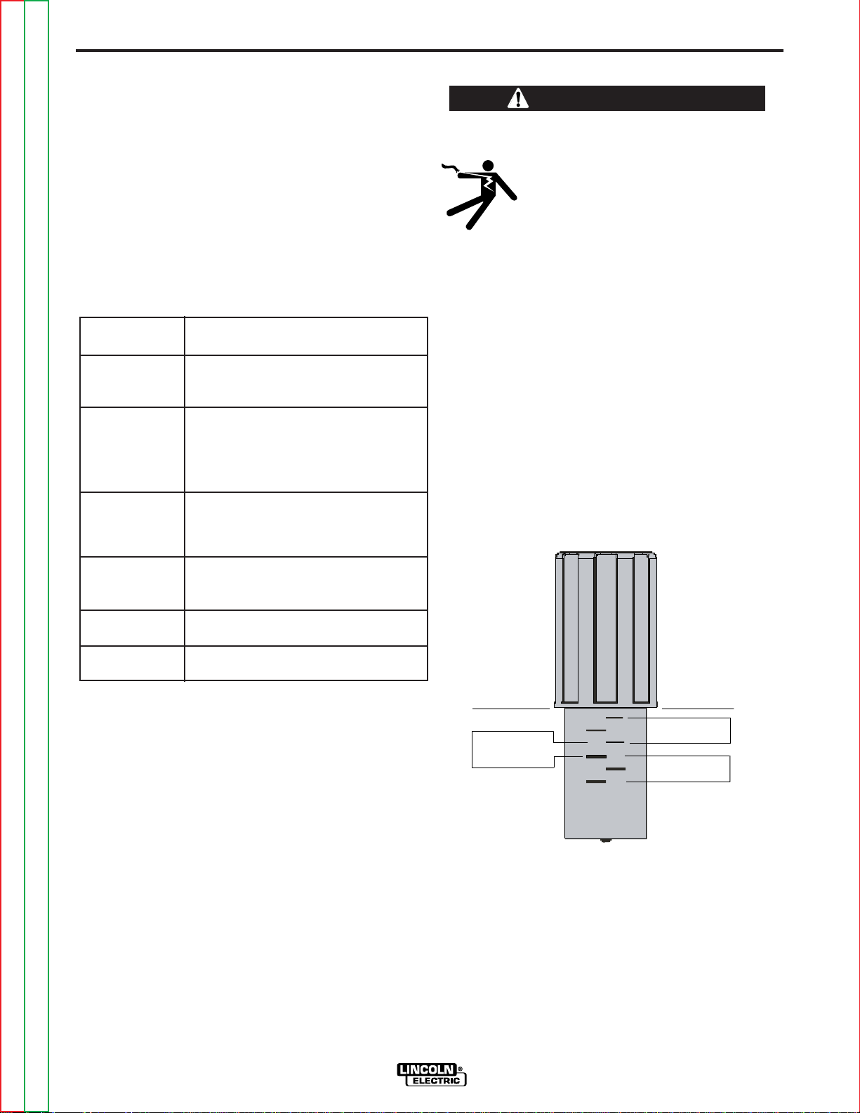
PRESSURE ARM ADJUSTMENT
WARNING
ELECTRIC SHOCK can kill.
• Turn the input power OFF at the
welding power source before installation or changing drive rolls and/or
guides.
• Do not touch electrically live parts.
• When inching with the gun trigger, electrode and
drive mechanism are "hot" to work and ground
and could remain energized several seconds
after the gun trigger is released.
• Only qualified personnel should perform maintenance work.
------------------------------------------------------------------------
The pressure arm controls the amount of force the
drive rolls exert on the wire. Proper adjustment of the
pressure arm gives the best welding performance.
Set the pressure arm as follows (See Figure A.6):
Aluminum wires between 1 and 3
Cored wires between 3 and 4
Steel, Stainless wires between 4 and 6
K1500-3 K1637-7 Lincoln gun connectors;
Magnum 550 guns and compatible
with Tweco® #5)
K1500-4 K466-3 Lincoln gun connectors;
compatible with Miller® guns.)
K1500-5 (Compatible with Oxo® guns.)
K489-7 ( Lincoln Fast-Mate guns.)
FIGURE A.6
Return to Master TOC Return to Master TOC Return to Master TOC Return to Master TOC
Return to Section TOC Return to Section TOC Return to Section TOC Return to Section TOC
LF-72/74
Page 19
A-13 A-13
INSTALLATION
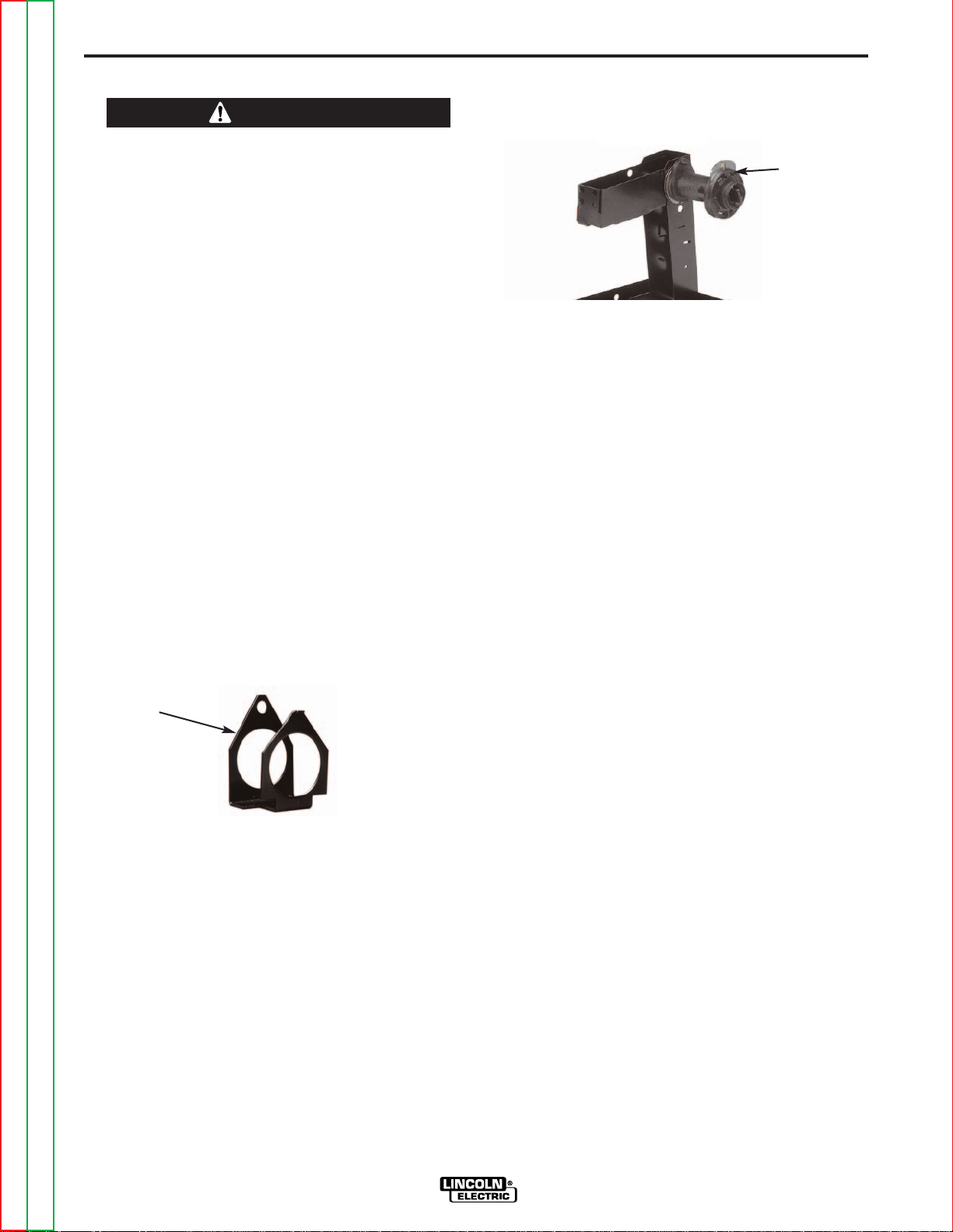
WIRE REEL LOADING
WARNING
• Keep hands, hair, clothing and tools away from
rotating equipment.
• Do not wear gloves when threading wire or
changing wire spool.
• Only qualified personnel should install, use or
service this equipment.
-----------------------------------------------------------------------
Loading 10 to 15 lb. (4.5 – 6.8kg) Spools
A K468 spindle adapter is required for loading 2" wide
spools on 2" (51mm) spindles. Use a K468-1 spindle
adapter for loading 2-1/2" (64mm) wide spools. (See
figure A.7 and figure A.8)
1. Squeeze the release bar on the retaining collar and
remove it from the spindle.
2. Place the spindle adapter on the spindle, aligning
the spindle brake pin with the hole in the adapter.
3. Place the spool on the spindle and align the adapter
brake tab with one of the holes in the back side of
the spool. An indicator mark on the end of the spindle shows the orientation of the brake tab. Be certain the wire feeds off of the spool in the proper
direction.
4. Re-install the retaining collar. Make sure that the
release bar snaps out and that the retaining collar
fully engages the groove on the spindle.
FIGURE A.7
Adapter
Spindle Placement
The wire reel stand provides two mounting locations
for the spindle. Each mounting location consists of a
tube in the center of the mast and locating slots.
Loading 16 to 44 lb. (7.3 – 20kg) Spools
(See figure A.8)
1. Squeeze the release bar on the retaining collar and
remove it from the spindle.
2. Place the spool on the spindle, aligning the spindle
brake pin with one of the holes in the back side of
the spool. An indicator mark on the end of the spindle shows the orientation of the brake holding pin.
Be certain the wire feeds off of the spool in the proper direction.
3. Re-install the retaining collar. Make sure that the
release bar snaps out and that the retaining collar
fully engages the groove on the spindle.
FIGURE A.8
Retaining
Collar
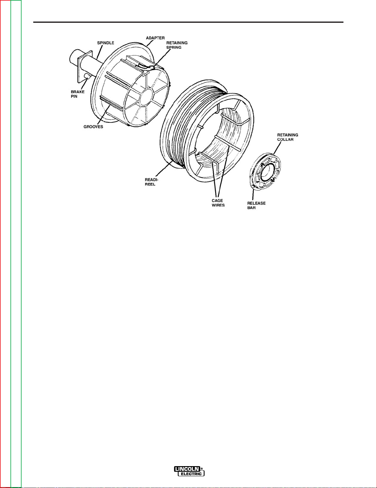
Loading 30 lb. (13.6 kg) Readi-Reels
(See Figure A.9)
A K363-P Readi-Reel adapter is required for loading
these spools on 2" (51mm) spindles.
1. Squeeze the release bar on the retaining collar and
remove it from the spindle.
2. Place the Readi-Reel adapter on the spindle, aligning the spindle brake pin with one of the holes in the
adapter.
3. Re-install the retaining collar. Make sure that the
release bar snaps out and that the retaining collar
fully engages the groove on the spindle.
4. Rotate the spindle and adapter until the retaining
spring is at the 12 o’clock position.
5. Position the Readi-Reel so that electrode de-reels in
the proper direction.
6. Set one of the Readi-Reel inside cage wires on the
slot in the retaining spring.
7. Lower the Read-Reel to depress the retaining
spring and align the other inside cage wires with the
grooves in the adapter.
8. Slide the cage all way onto the adapter until the
retaining spring "pops up" fully.
Removing a Readi-Reel
1. To remove a Readi-Reel from the an adapter,
depress the retaining spring with a thumb while
pulling the Readi-Reel cage from the adapter with
both hands. Do not remove the adapter from the
spindle.
Return to Master TOC Return to Master TOC Return to Master TOC Return to Master TOC
Return to Section TOC Return to Section TOC Return to Section TOC Return to Section TOC
LF-72/74
Page 20
A-14 A-14
INSTALLATION
FIGURE A.9
WELD WIRE ROUTING
The electrode supply may be either from reels, ReadiReels, spools, or bulk packaged drums or reels.
Observe the following precautions:
a) The electrode must be routed to the wire drive unit
so that the bends in the wire are at a minimum,
and also that the force required to pull the wire
from the reel into the wire drive unit is kept at a
minimum.
b) The electrode is “hot” when the gun trigger is
pressed and must be insulated from the boom and
structure.
c) If more than one wire feed unit shares the same
boom and are not sharing the some power source
output stud, their wire and reels must be insulated
from each other as well as insulated from their
mounting structure.
Return to Master TOC Return to Master TOC Return to Master TOC Return to Master TOC
Return to Section TOC Return to Section TOC Return to Section TOC Return to Section TOC
LF-72/74
Page 21

A-15 A-15
INSTALLATION
SHIELDING GAS CONNECTION
CYLINDER may explode if damaged.
• Keep cylinder upright and chained to
support.
• Keep cylinder away from areas where
it may be damaged.
• Never lift welder with cylinder attached.
• Never allow welding electrode to touch cylinder.
• Keep cylinder away from welding or other live
electrical circuits.
------------------------------------------------------------------------
BUILD-UP OF SHIELDING GAS may
harm health or kill.
• Shut off shielding gas supply when
not in use.
SEE AMERICAN NATIONAL STANDARD Z-49.1,
"SAFETY IN WELDING AND CUTTING" PUBLISHED BY THE AMERICAN WELDING SOCIETY.
------------------------------------------------------------------------
Maximum inlet pressure is 100 psi. (6.9 bar.)
5. Attach one end of the inlet hose to the outlet fitting
of the flow regulator. Attach the other end to the
welding system shielding gas inlet. Tighten the
union nuts with a wrench.
6. Before opening the cylinder valve, turn the regulator
adjusting knob counterclockwise until the adjusting
spring pressure is released.
7. Standing to one side, open the cylinder valve slowly
a fraction of a turn. When the cylinder pressure gage
stops moving, open the valve fully.
8. The flow regulator is adjustable. Adjust it to the flow
rate recommended for the procedure and process
being used before making a weld.
Install the shielding gas supply as follows:
1. Secure the cylinder to prevent it from falling.
2. Remove the cylinder cap. Inspect the cylinder
valves and regulator for damaged threads, dirt, dust,
oil or grease. Remove dust and dirt with a clean
cloth. DO NOT ATTACH THE REGULATOR IF OIL,
GREASE OR DAMAGE IS PRESENT! Inform your
gas supplier of this condition. Oil or grease in the
presence of high pressure oxygen is explosive.
3. Stand to one side away from the outlet and open the
cylinder valve for an instant. This blows away any
dust or dirt which may have accumulated in the
valve outlet.
4. Attach the flow regulator to the cylinder valve and
tighten the union nut(s) securely with a wrench.
Note: if connecting to 100% CO
ulator adapter between regulator and cylinder valve.
If adapter is equipped with a plastic washer, be sure
it is seated for connection to the CO
cylinder, insert reg-
2
cylinder.
2
Return to Master TOC Return to Master TOC Return to Master TOC Return to Master TOC
Return to Section TOC Return to Section TOC Return to Section TOC Return to Section TOC
LF-72/74
Page 22

A-16 A-16
"O" RING
INSTALLATION
INSTALLING ELECTRODE
CONDUIT KITS
WARNING
ELECTRIC SHOCK can kill.
• Turn the input power OFF at the disconnect switch before working on
this equipment.
• Do not touch electrically hot parts.
------------------------------------------------------------------------
Electrode conduit is used when feeding wire drums,
from boxes or large reels. For best feeding results, use
the shortest conduit length possible and avoid
bends.
(For Codes 11075, 11076, 11077)
Tools required: (See Figure A.10a)
• Snap Ring Pliers
To install Lincoln conduit:
sharp
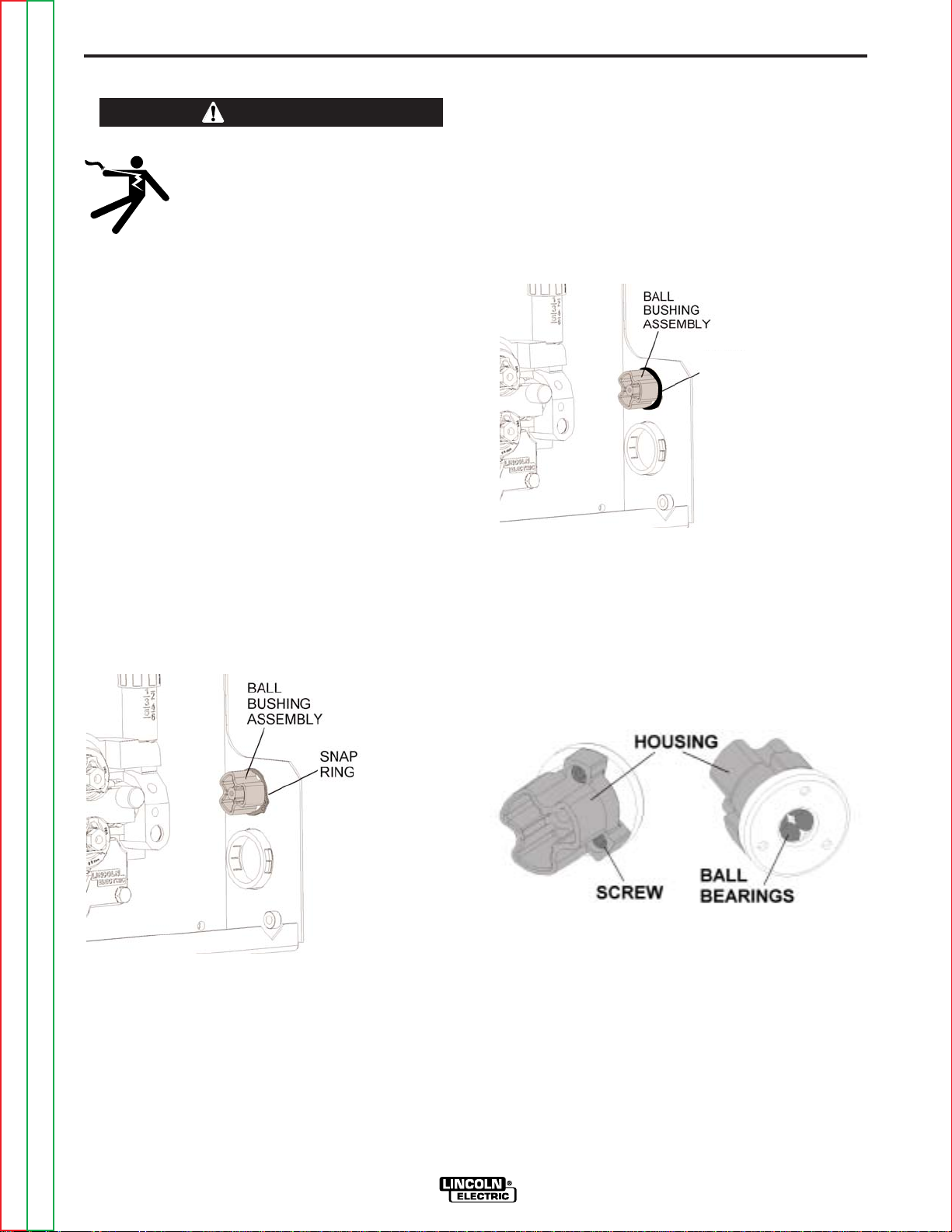
(For Codes 11209, 11210, 11211 and above)
To install Lincoln conduit:
1. Turn off power at the welding power source.
2. Remove the “O” ring holding the ball bushing
assembly to the back of the wire feeder. Remove
the ball bushing assembly.
(See Figure A.10b)
FIGURE A.10b
1. Turn off power at the welding power source.
2. Remove the snap ring holding the ball bushing
assembly to the back of the wire feeder. Remove
the ball bushing assembly.
FIGURE A.10a
3. Place a K1546-xx conduit connector into the back of
the wire drive. Rotate the conduit connector to a
position where the thumb screw does not interfere
with the idle arm or door.
4. Tighten the set screw to secure the conduit connector in the wire drive.
5. Insert conduit through the sheet metal of the LF-72
and into the conduit connector. Secure with the
thumb screw.
FIGURE A.11
Return to Master TOC Return to Master TOC Return to Master TOC Return to Master TOC
Return to Section TOC Return to Section TOC Return to Section TOC Return to Section TOC
LF-72/74
Page 23
A-17 A-17
"O" RING
INSTALLATION
ALUMINUM WIRE PREPARATIONS
WARNING
ELECTRIC SHOCK can kill.
• Turn the input power OFF at the disconnect switch before working on
this equipment.
• Do not touch electrically hot parts.
-----------------------------------------------------------------------Welding with aluminum filler wires requires extra care.
Aluminum wire is softer and not as stiff as steel wires,
it is important to keep aluminum wire free of dirt and
scratches. Limit gun length to 10 Ft.(3.0 m) for best
results and use a spool cover if feeding from a spool.
To prevent scratching of the aluminum wire, remove
the ball bearings from the ball housing as follows.
(For Codes 11075, 11076, 11077)
Tools required: (See Figure A.12a)
• Snap Ring Pliers
• 9/64" Hex key wrench
FIGURE A.12a
(For Codes 11209, 11210, 11211 and above)
Tools required: (See Figure A.12b)
• 9/64" Hex key wrench
1. Turn off power at the welding power source.
2. Remove the snap ring holding the ball bushing
assembly to the back of the wire feeder. Remove the
ball bushing assembly.
1. Turn off power at the welding power source.
2. Remove the snap ring holding the ball bushing
assembly to the back of the wire feeder. Remove the
ball bushing assembly.
FIGURE A.12b
3. Remove the three socket head cap screws from the
ball bushing assembly. Caution: as the screws are
being loosened, the balls may fall free from the
assembly.
4. Place the ball bushing housing into the wire feeder
case and secure with the snap ring or “O” ring
depending on which code your machine uses.
Remove the balls and the steel washer.
FIGURE A.13
Return to Master TOC Return to Master TOC Return to Master TOC Return to Master TOC
Return to Section TOC Return to Section TOC Return to Section TOC Return to Section TOC
LF-72/74
Page 24

A-18 A-18
INSTALLATION
BASE MODEL
BENCH MODEL STANDARD DUTY
BENCH MODEL HEAVY DUTY
Return to Master TOC Return to Master TOC Return to Master TOC Return to Master TOC
Return to Section TOC Return to Section TOC Return to Section TOC Return to Section TOC
LF-72/74
Page 25
A-19 A-19
INSTALLATION
TYPICAL SYSTEM CONFIGURATIONS
The LF-72 is capable of welding with many different welding processes. These processes may require reconfiguring the LF-72 with other products that may or may not be included with the model you purchased. Use the Table
1 below to identify the basic items which are included in the LF-72 to utilize the various Welding Processes that
the machine is capable of controlling.
TABLE 1
PART NO.
K2327-1
K2327-2
K2327-3
K2327-4
Description
Base Model
Bench Model,
Standard Duty
Bench Model,
Heavy Duty
Base Model
Wire
Feeder
LF-72
Gun
15', Magnum 400,
.035-.045 (0.9-1.2 mm)
---
Wire Reel Stand
---
Standard duty, up to
44 lb. (20 kg)spools.
Heavy Duty, up to
60 lb. (27.2 kg) coils.
---
Drive Roll Kit
.035-.045 combo
(0.9-1.2 mm)
CONTROL
CABLE
10’ (3m)
---
Return to Master TOC Return to Master TOC Return to Master TOC Return to Master TOC
Return to Section TOC Return to Section TOC Return to Section TOC Return to Section TOC
LF-72/74
Page 26

A-20 A-20
NOTES
Return to Master TOC Return to Master TOC Return to Master TOC Return to Master TOC
Return to Section TOC Return to Section TOC Return to Section TOC Return to Section TOC
LF-72/74
Page 27

Section B-1 Section B-1
TABLE OF CONTENTS
- OPERATION SECTION -
Operation ................................................................................................................Section B
Safety Precautions .......................................................................................................B-2
Graphic Symbols..........................................................................................................B-2
Common Welding Abbreviations..................................................................................B-3
Product Description......................................................................................................B-3
Recommended Processes and Required Equipment..................................................B-3
Front Panel Controls and Connections........................................................................B-4
1. Remote Voltage Control Kit (Optional)................................................................B-5
2. Burnback and Postflow Timer Kit (Optional) ......................................................B-5
3. Thermal LED, Motor Overload............................................................................B-5
4. Cold Feed/Gas Purge Switch .............................................................................B-5
5. 2 Step - Trigger Interlock Switch.................................................................B-5/B-6
6. Wire Feed Speed Knob ......................................................................................B-6
7. Gun Receiver Bushing ........................................................................................B-6
8. Trigger Connector 5-Pin Amphenol ....................................................................B-6
Return to Master TOC Return to Master TOC Return to Master TOC Return to Master TOC
LF-72/74 SINGLE/DUAL
Page 28
B-2 B-2
OPERATION
SAFETY PRECAUTIONS
Read this entire section of operating instructions
before operating the machine.
WARNING
ELECTRIC SHOCK can kill.
• Unless using cold feed feature, when
feeding with the gun trigger, the
electrode and drive mechanism are
always electrically energized and
could remain energized several seconds after welding ceases.
• Do not touch electrically live parts or electrodes
with your skin or wet clothing.
• Insulate yourself from the work and ground.
• Always wear dry insulating gloves.
-------------------------------------------------------------
ONLY QUALIFIED PERSONS SHOULD INSTALL,
USE OR SERVICE THIS EQUIPMENT. READ AND
FOLLOW THE MANUFACTURER’S INSTRUCTIONS, EMPLOYER’S SAFETY PRACTICES AND
MATERIAL SAFETY DATA SHEETS (MSDS) FOR
CONSUMABLES.
The serviceability of a product or structure utilizing
the LF-72 wire feeder is and must be the sole responsibility of the builder/user. Many variables beyond
the control of The Lincoln Electric Company affect the
results obtained in using the LF-72 wire feeder.
These variables include, but are not limited to, welding procedure, plate chemistry and temperature,
weldment design, fabrication methods and service
requirements. The available range of the LF-72 wire
feeder may not be suitable for all applications, and
the builder/user is and must be solely responsible for
welding settings.
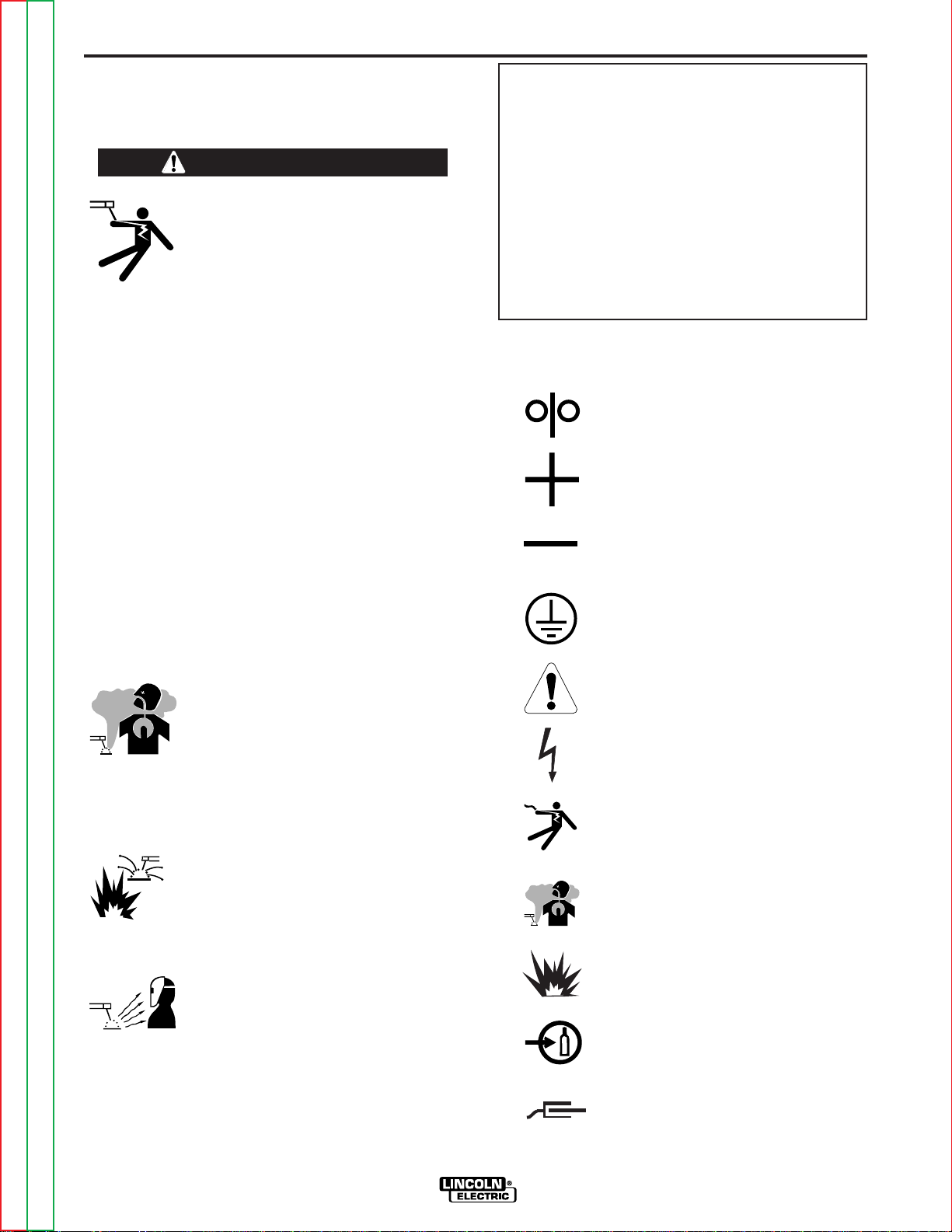
GRAPHIC SYMBOLS THAT APPEAR ON
THIS MACHINE OR IN THIS MANUAL
COLD FEED
POSITIVE OUTPUT
NEGATIVE OUTPUT
-----------------------------------------------------------
READ THIS WARNING, PROTECT YOURSELF &
OTHERS.
FUMES AND GASES can be
dangerous.
• Keep your head out of fumes.
• Use ventilation or exhaust at the arc,
or both, to keep fumes and gases
from your breathing zone and general area.
WELDING SPARKS can cause
fire or explosion.
• Do not weld near flammable material.
• Do not weld on containers which have held flammable material.
ARC RAYS can burn.
• Wear eye, ear, and body protection.
PROTECTIVE
GROUND
WARNING OR
CAUTION
DANGEROUS
VOLTAGE
SHOCK
HAZARD
WELDING
FUMES
EXPLOSION
GAS INPUT
-----------------------------------------------------------
Observe additional guidelines detailed in the
beginning of this manual.
Return to Master TOC Return to Master TOC Return to Master TOC Return to Master TOC
Return to Section TOC Return to Section TOC Return to Section TOC Return to Section TOC
LF-72/74
WORK
CONNECTION
Page 29

B-3 B-3
OPERATION
PROCESS LIMITATIONS
COMMON WELDING ABBREVIATIONS
• Rated for up to 1/16(1.6 mm) solid electrode and 5/64
WFS
• Wire Feed Speed
CV
• Constant Voltage
GMAW (MIG)
• Gas Metal Arc Welding
FCAW (Cable Innershield or Outershield)
• Flux Core Arc Welding
(2.0 mm) cored electrode.
• The maximum WFS is 800 in/min (20.3 M/min).
• The LF-72 is not recommended for GMAW-Pulse
(synergic), GTAW, GTAW-Pulse, SAW, CAG, SMAW.
• Do not use push-pull equipment with the LF-72.
• For K2327-2 Bench model, std. duty: Maximum
spool size = 44 lb. (20 kg); 12 inch (300mm) diameter; 4 inch (100mm)
• For K2327-3 Bench model, heavy duty: Maximum
spool size = 60 lb. (27.2 kg)
REQUIRED EQUIPMENT
PRODUCT DESCRIPTION
General Physical Description
Lincoln’s LF-72 is designed for use with the CV and DC
family of power sources. These include:
The LF-72 is optimized for .035 through .045 (0.9mm
through 1.2mm) GMAW welding. The powerful 2 roll
drive, heavy duty enclosure and wire reel stand combine to make an easy to install, easy to use wire feeder for everyday welding. Powering the wire drive is a
high performance motor gearbox. A heavy duty hinged
door opens easily, which provides an ample amount of
room for assembling precision drive components and
the welding gun. Also under the door is a convenient
storage tray for contact tips and tools.
Three packages are available. The basic unit consists
of the wire drive box housing. The standard duty bench
model targets users of 12" (305 mm)diameter spools.
The heavy duty bench model satisfies the needs of
customers using 60 lb (27.2 kg) spools.
General Functional Description
• The LF-72 is a highly versatile and economical choice
of industrial feeders. Easy to use features are a calibrated WFS knob, cold-feed/ gas purge switch and
trigger interlock.
• Several kits are available to expand the LF-72’s welding capability. The timer kit allows adjustment of burnback and postflow times. The remote voltage control
kit includes a 0 to 10 dial for setting the welding voltage at the wire feeder. The swivel kit mounts to the lift
bail of a power source and lets the feeder freely
rotate so the gun cable stays straight.
• CV-305 • DC-400
• CV-400 • DC-600
• CV-655 • Invertec™ V350
• Invertec™ V450
EQUIPMENT LIMITATIONS
• Maximum gun length =25 ft. (7.6m)
• Maximum conduit length = 30 ft. (9.1m)
• Maximum total control cable length = 100ft (31m)
• The LF-72 operates on 42VAC and not 115 VAC
• The K1733-1 wire straightener may not be used with
the LF-72
• Gun bushings are required for welding guns that do
not have a Magnum (Tweco #2-#4 compatible) back
end.
• The LF-72 does not attach to K303 wire reel stands.
RECOMMENDED PROCESSES
• GMAW .023-1/16 (0.6 - 1.6 mm) steel electrodes.
• FCAW .035 -5/64 (0.9 - 2.0mm) cored electrodes
Return to Master TOC Return to Master TOC Return to Master TOC Return to Master TOC
Return to Section TOC Return to Section TOC Return to Section TOC Return to Section TOC
LF-72/74
Page 30
B-4 B-4
OPERATION
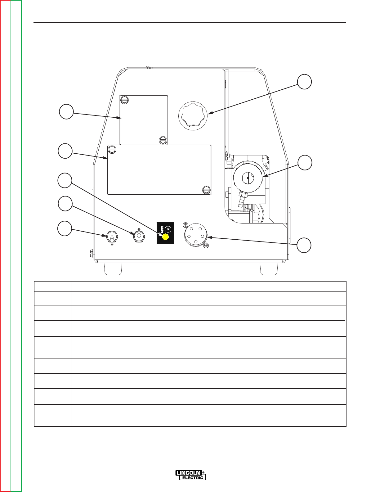
FRONT PANEL CONTROLS AND CONNECTIONS
FIGURE B.1 CASE FRONT CONTROLS
6
1
2
7
3
4
5
ITEM DESCRIPTION
1
2
3 Thermal LED, Motor Overload.
4 Cold Feed - Gas Purge Switch, press the switch up to feed wire with weld output off.
5 2 step - Trigger Interlock switch.
6 Wire Feed Speed Knob.
Location for Optional
Location for Optional Burnback and Postflow Timer Kit (See Accessory Section For Kit Number).
Press the switch down for gas flow with weld output off.
Remote Voltage Control
(See Accessory Section For Kit Number).
8
7 Gun Receiver Bushing.
8 Trigger Connector 5-pin amphenol for connecting the MIG gun trigger. See Installation Section
for detail.
Return to Master TOC Return to Master TOC Return to Master TOC Return to Master TOC
Return to Section TOC Return to Section TOC Return to Section TOC Return to Section TOC
LF-72/74
Page 31

B-5 B-5
OPERATION
1. REMOTE VOLTAGE CONTROL KIT
The optional remote voltage control kit adjusts the
arc voltage from the minimum to the maximum voltage of the welding power source. Rotate the knob
counterclockwise to reduce the arc voltage and rotate
the knob clockwise to raise the arc voltage.
2. BURNBACK AND POSTFLOW TIMER KIT
The optional Burnback and Postflow Timer Kit gives
control over the shielding gas at the end of the weld
and prepares the end of the wire for the next arc start.
Additional shielding gas protection is often required
when welding aluminum, stainless steel or exotic
alloys.
When stitch welding, set the postflow time to maximum for best results.
3. THERMAL LED, MOTOR OVERLOAD
The thermal light illuminates when the wire drive
motor draws too much current. If the thermal light illuminates, the wire drive will automatically shutdown for
up to 30 seconds to allow the motor to cool. To start
welding again, release the gun trigger, inspect the gun
cable, liner (and conduit). Clean and make repairs as
necessary. Start welding again when the problem has
been safely resolved.
For best results, keep the gun cable and conduit as
straight as possible. Perform regular maintenance
and cleaning on the gun liner, conduit and gun.
Always use quality electrode, such as L-50 or L-56
from Lincoln Electric.
4. COLD FEED/GAS PURGE SWITCH
Cold Feed and Gas Purge are combined into a single
spring centered toggle switch.
To activate Cold Feeding, hold the switch
in the UP position. The wire drive will
feed electrode but neither the power
source nor the gas solenoid will be energized. Adjust the speed of cold feeding
by rotating the WFS knob. Cold feeding,
or "cold inching" the electrode is useful
for threading the electrode through the gun.
Burnback Timer
The burnback timer range is OFF to 0.25 seconds.
The burnback timer controls the additional amount of
time the power source output remains ON after the
wire drive has stopped feeding wire. Burnback
adjustment prevents the wire from sticking to the weld
at the end of a weld and helps to condition the wire for
the next weld.
To set the burnback time, adjust the knob to approxi-
mately 0.03 seconds and then decrease or increase
the time as desired.
Postflow Timer
The postflow timer range is OFF to 10 seconds.
Postflow is the time from when the power source output turns OFF until the postflow timer expires. Use
postflow to protect the weld while the weld cools.
Return to Master TOC Return to Master TOC Return to Master TOC Return to Master TOC
Return to Section TOC Return to Section TOC Return to Section TOC Return to Section TOC
LF-72/74 SINGLE/DUAL
Hold with toggle switch in the DOWN position to activate Gas Purge and let the shielding gas flow. The
gas solenoid valve will energize but neither the power
source output nor the drive motor will be turned on.
The Gas Purge switch is useful for setting the proper
flow rate of shielding gas. Flow meters should always
be adjusted while the shielding gas is flowing.
5.
2 STEP - TRIGGER INTERLOCK SWITCH
The 2 Step - Trigger Interlock switch
changes the function of the gun trigger. 2
Step trigger operation turns welding on
and off in direct response to the trigger.
Trigger Interlock operation allows welding
to continue when the trigger is released
for comfort on long welds.
Place the toggle switch in the DOWN position for 2
Step operation or in the UP position for Trigger
Interlock operation.
2 Step Trigger
2 Step trigger operation is the most common. When
the gun trigger is pulled, the welding power source
energizes the electrode output and the wire feeder
feeds wire for welding. The power source and wire
feeder continue welding until the trigger is released.
Page 32

B-6 B-6
Trigger Interlock
Trigger Interlock operation provides for operator comfort when making long welds. When the gun trigger is
first pulled, the welding power source energizes the
output and the wire feeder feeds wire for welding. The
gun trigger is then released while the weld is made. To
stop welding, the gun trigger is pulled again, and when
it is released the welding power source output turns off
and the wire feeder stops feeding wire.
OPERATION
CAUTION
• If the arc goes out while welding with
trigger interlock operation, the electrode output from the welding power
source remains energized and the
wire feeder will continue to feed wire
until the gun trigger is again pulled
and then released.
------------------------------------------------------------------------
6. WIRE FEED SPEED KNOB
The large, calibrated wire feed speed knob makes for
easy and accurate adjustment of the wire feed speed.
The knob rotates 3/4 turn. Turn the knob clockwise to
increase the wire feed speed, and counter clockwise
to reduce the wire feed speed.
The wire feed speed range is 50 to 800 in/min (1.27 -
20.3 m/min).
7. GUN RECEIVER BUSHING (K1500-2)
(K1500-2 bushing is standard on all LF-72's)
This Gun Receiver Bushing is used with Lincoln gun
connectors, also with Magnum 200/300/400 guns and
compatible with Tweco® #4).
8.
TRIGGER CONNECTOR 5-PIN AMPHENOL
This is used for connecting the MIG gun trigger. See
Installation Section for detail.
Return to Master TOC Return to Master TOC Return to Master TOC Return to Master TOC
Return to Section TOC Return to Section TOC Return to Section TOC Return to Section TOC
LF-72/74
Page 33

Section C-1 Section C-1
TABLE OF CONTENTS
- ACCESSORIES SECTION -
Accessories ............................................................................................................Section C
General Options / Accessories .............................................................................C-2/C-5
Return to Master TOC Return to Master TOC Return to Master TOC Return to Master TOC
LF-72/74 SINGLE/DUAL
Page 34

C-2 C-2
ACCESSORIES
OPTIONAL KITS:
Includes: 10k potentiometer,
K2329-1
K2330-1
K2328-1
Remote Voltage Control Kit.
Timer Kit.
Standard Duty Wire Reel Stand.
harness, knob and decal with
a 0-10 scale and mounting
hardware.
Includes: Panel and harness
for adjusting burnback and
postflow times.
Includes: Wire Reel Stand for
up to 44 lbs (20 kg) spools,
Spindle and mounting hard-
ware.
K2331-1
K2332-1
K1796-xx
K1803-1
K1840-xx
K1841-xx
Lift Bail Kit.
Swivel Kit.
(for use with Standard Duty Bench
Models)
Co-Axial Power Cable.
Work and Feeder Cables
Package.
Weld Power Cable, Twist-Mate to
Lug.
Weld Power Cable,
Twist-Mate to Twist-Mate.
Includes: Insulated lift bail
and hardware.
Includes: Swivel adapter and
mounting hardware for attaching to a power source lift bale.
Includes: Coaxial weld cable
of length "xx". Ends of the
weld cable have lug connec-
tions. Use for Pulse or STT
welding.
Includes: Twist-Mate to Lug
2/0 cable 14' (1.2m) long with
Ground Clamp, and Twist-
Mate to Lug 2/0 Cable 9'
(2.7m) long.
Includes: Twist-Mate to Lug,
1/0 cable of length "xx".
Includes: Twist-Mate to TwistMate, 1/0 Cable for 25' (7.6m)
cables.
Includes: Twist-Mate to Twist-
Mate, 2/0 Cable for 50'
(15.2m) cables.
Includes: Lug to Lug, 3/0
Cable of length "xx" for
K1842-xx
Return to Master TOC Return to Master TOC Return to Master TOC Return to Master TOC
Return to Section TOC Return to Section TOC Return to Section TOC Return to Section TOC
Weld Power Cable, Lug to Lug.
lengths up to 60' (18.3m).
Lug to Lug, 4/0 Cable of
length "xx" for lengths greater
than 60' (18.3m).
LF-72/74
Page 35

C-3 C-3
ACCESSORIES
OPTIONAL KITS:
Includes: 14 pin to 14 pin wire
K1797-xx
K2335-1
K1520-1
Adapter for Miller Power Sources.
Control Cable.
42 Volt Transformer Kit.
feeder to power source control
cable.
Includes: Adapter control
cable for connecting a Lincoln
42 VAC wire feeder to a 24
VAC Miller power source.
Includes: One transformer kit
for operating a 42 VAC wire
feeder on a power source
supplying only 115 VAC.
K1798
K910-1
K910-2
K1500-1
K1500-2
(standard on all
LF-72's)
K1500-3
K1500-4
Adapter Cable for Control Cable to
Terminal Strip Power Sources.
Ground Clamp.
Ground Clamp.
Gun Receiver Bushing (for guns
with K466-1 Lincoln gun connec-
tors; Innershield and Subarc
guns.)
Gun Receiver Bushing (for guns with
K466-2, K466-10 Lincoln gun con-
nectors; Magnum 200/300/400 guns
and compatible with Tweco® #4.)
Gun Receiver Bushing (for guns
with K613-7 Lincoln gun connec-
tors; Magnum 550 guns and com-
patible with Tweco® #5.)
Gun Receiver Bushing (for gun
with K466-3 Lincoln gun connec-
tors; compatible with Miller®
guns.)
Includes:
Includes: One 300 Amp
Ground Clamp.
Includes: One 500 Amp
Ground Clamp.
Includes: Gun receiver bush-
ing, set screw and hex key
wrench.
Includes: Gun receiver bush-
ing with hose nipple, set
screw and hex key wrench.
Includes: Gun receiver bush-
ing with hose nipple, set
screw and hex key wrench.
Includes: Gun receiver bush-
ing with hose nipple, set
screw and hex key wrench.
Includes: Gun receiver bush-
K1500-5
Return to Master TOC Return to Master TOC Return to Master TOC Return to Master TOC
Return to Section TOC Return to Section TOC Return to Section TOC Return to Section TOC
Gun Receiver Bushing (compatible
with Oxo® guns.)
ing with hose nipple, 4 guide
tubes, set screw and hex key
wrench.
LF-72/74
Page 36

C-4 C-4
ACCESSORIES
OPTIONAL KITS:
K489-7
K466-2
K613-7
K1546-1
K1546-2
K435
K468
Gun Receiver Bushing (for Lincoln
Fast-Mate guns.)
Magnum 200/300/400 to K1500-2
Adapter.
Magnum 550 to K1500-3 Adapter
Lincoln Conduit.
Incoming Bushing, for Lincoln
Conduit .025- 1/16" (0.6 - 1.6mm)
wire.
Incoming Bushing, for Lincoln
Conduit 1/16-1/8" (1.6 - 3.2 mm )
wire.
Spindle Adapter, for mounting 14
lb. (6.4 kg) Innershield Coils on 2
in (51 mm) spindles.
Spindle Adapter, for mounting 8in
(203mm) diameter spools on 2 in
(51 mm) spindles.
Includes: Gun receiver bush-
ing with trigger connector.
Includes: Gun adapter, cotter
pin, hex key wrench, wrench.
Includes: Trigger adapter, gun
adapter and hex key wrench.
Includes: Incoming bushing
and hex key wrench.
Includes: Incoming bushing
and hex key wrench.
Includes: Spindle Adapter
made from 2 coil retainers.
(Electrode not included.)
Includes: Spindle Adapter.
K363P
K438
K1504-1
Readi-Reel Adapter, for mounting
23-30 lb. (10.4 - 13.6 kg) reels to 2
in (51 mm) spindles.
Readi-Reel Adapter, for mounting
50-60 lb. (22.7 - 27.2 kg) reels to
2 in (51 mm) spindles. For use
with Heavy Duty Bench models.
Coil Adapter, for mounting 50-60
lb. (22.7 - 27.2 kg) coils to 2 in (51
mm) spindles.
For use with heavy Duty Bench
Includes: Readi-Reel spool
adapter. (Spool of electrode
not included.)
Includes: Readi-Reel spool
adapter. (Spool of electrode
not included.)
Includes: 50-60 lb. (22.7 -
27.2 kg) coil adapter.
Return to Master TOC Return to Master TOC Return to Master TOC Return to Master TOC
Return to Section TOC Return to Section TOC Return to Section TOC Return to Section TOC
LF-72/74
Page 37

C-5 C-5
ACCESSORIES
OPTIONAL KITS:
Includes: Cover, backing
K1634-1
Plastic Wire Cover for 30-44 lb.
(13.6 - 20.0 kg) Wire packages.
(For use with Standard Duty
Bench Models and Heavy Duty
Bench Models.)
plate, wire conduit, incoming
bushing for .025 - 1/16" (0.6 -
1.6 mm) wire, incoming bushing for 1/16" - 1/8" (1.6 - 3.2
mm) wire, thumb screw,
mounting hardware and hex
key.
K1634-2
K659-1
3000290
K586-1
K1524-3
K163
Plastic Wire Cover for up to 60 lb.
(27.2kg) Wire packages. (For use
with Heavy Duty Bench Models.)
Gas Guard Regulator
Adjustable Gas Regulator
Deluxe Adjustable Gas Regulator
Heavy Duty Universal Wire Reel
Stand. For spools up to 60 lb.
(27.2kg)
4 Wheeled Wire Feeder
Undercarriage (For use with
Standard Duty Bench Models and
Heavy Duty Bench Models.)
Includes: Gas Guard
Regulator and adjustment key.
Includes: Gas Regulator for
Mixed Gases and 10' (3.0m)
Hose.
Includes: Deluxe Gas
Regulator for Mixed Gases,
Adapter for CO2 and 10'
(3.0m) Hose.
Includes: Heavy Duty Wire
Reel Stand.
Includes: Undercarriage with
8" (203mm) rear wheels, 4"
(102mm)casters.
K1557-1
K1556-1
K1555-1
Return to Master TOC Return to Master TOC Return to Master TOC Return to Master TOC
Return to Section TOC Return to Section TOC Return to Section TOC Return to Section TOC
Swivel Platform (for use with
Heavy Duty Bench Models)
Light Duty Caster Kit (for use with
Heavy Duty Bench Models)
Insulated Lift Bail
(for use with Heavy Duty Bench
Models)
LF-72/74
Includes: Swivel Platform and
Tray.
Includes: 2 Swivel Casters, 2
Fixed Casters, brackets and
mounting hardware.
Includes: Insulated Lift Bail
and mounting hardware.
Page 38

C-6 C-6
NOTES
Return to Master TOC Return to Master TOC Return to Master TOC Return to Master TOC
Return to Section TOC Return to Section TOC Return to Section TOC Return to Section TOC
LF-72/74
Page 39

Section D-1 Section D-1
TABLE OF CONTENTS
- MAINTENANCE SECTION -
Maintenance ...........................................................................................................Section D
Safety Precautions ........................................................................................................D-2
Routine Maintenance.....................................................................................................D-2
Periodic Maintenance....................................................................................................D-2
Calibration Specification ........................................................................................D-2/D-3
Major Component Locations.........................................................................................D-4
Return to Master TOC Return to Master TOC Return to Master TOC Return to Master TOC
LF-72/74 SINGLE/DUAL
Page 40

D-2 D-2
MAINTENANCE
MAINTENANCE
Safety Precautions
WARNING
ELECTRIC SHOCK can kill.
• Do not touch electrically live parts
such as output terminals or internal wiring.
• When inching with gun trigger, electrode and
drive mechanism are “hot” to work and ground
and could remain energized several seconds
after the gun trigger is released.
• Turn OFF input power at welding power source
before installation or changing drive roll and/or
guide tubes.
• Welding power source must be connected to system ground per the National Electrical Code or
any applicable local codes.
• Only qualified personnel should perform maintenance work.
------------------------------------------------------------------------
Observe all additional Safety Guidelines detailed
throughout this manual.
ROUTINE MAINTENANCE
• Clean and tighten all weld terminals.
• Inspect all weld cables, control cables, gun cables
and shielding gas hoses. Repair or replace as necessary.
CALIBRATION SPECIFICATION
WARNING
ELECTRIC SHOCK can kill.
• Do not touch electrically live parts.
• When inching with the gun trigger,
electrode, wire drive motor and
drive mechanism are "hot" to work
and ground and could remain
energized several seconds after
the gun trigger is released.
• Welding power source must be
connected to system ground per
the National Electrical Code or any
applicable local codes.
• Only qualified personnel should perform maintenance work.
------------------------------------------------------------------------
Calibration of the LF-72 may be required when the p.c.
board, potentiometer or motor is replaced or serviced.
Calibration matches the scale on the name plate to the
actual wire feed speed.
To verify if calibration is necessary:
1. Turn off power to the LF-72.
2. Assemble .045 drive rolls, inner guide and the
outer guide into the drive. Remove the gun from
the wire feeder if assembled.
3. Load .045 wire into the drive. Cut the wire flush
with the end of the gun bushing.
4. Set the WFS knob to 300 ipm.
5. Using the COLD FEED switch, feed wire for 10
seconds.
6. Cut the wire flush with the end of the gun bushing.
Measure the length of the wire. If the wire measures 50 ± 2.5 inches then calibration is not
required.
Tools required:
PERIODIC MAINTENANCE
• Clean drive roll grooves.
• Blow out or vacuum the inside of the feeder.
To calibrate the LF-72:
1. Turn off power to the LF-72.
2. Disconnect the electrode lead from the feedplate
3. Remove the 5 screws securing the wraparound.
Return to Master TOC Return to Master TOC Return to Master TOC Return to Master TOC
Return to Section TOC Return to Section TOC Return to Section TOC Return to Section TOC
LF-72/74
5/16" nut driver
3/4" open end wrench
WFS meter or RPM meter
Shorting plug. The shorting plug shorts pins 1
& 5 of connector J2 on the p.c. board. J2 is a
6 pin molex connector.
and from the welding power source.
(The door is not shown for clarity. “
D.1”)
See Figure
Page 41

D-3 D-3
J2 CONNECTOR
MAINTENANCE
FIGURE D.1
4. Open the idle arm.
5. Turn power on to the LF-72.
6. Adjust the WFS knob to 300 ipm. Center the knob
pointer with the name plate graphics.Activate the
gun trigger.
7. Insert the shorting plug into connector J2 on the p.c.
board. The shorting plug shorts pins 1 & 5.
(See Figure D.2)
8. Remove the shorting plug. Set aside.
(For Codes below 11289 use 9 thru 17)
9. Adjust the WFS knob to minimum.
10. Insert the shorting plug into connector J2.
11. Adjust the WFS knob until the motor measures 51
± 5.5 ipm. (9.5 ± 1.0 rpm).
12. Remove the shorting plug.
(For Codes above 11290 use 18)
18. Replace P2 from the harness into connector J2.
19. Turn off power.
20. Secure the wraparound to the LF-72 with 5
screws.
FIGURE D.2
13. Adjust the WFS knob to maximum.
14. Insert the shorting plug into connector J2.
15. Adjust the WFS until the motor measures 793 ±
5.5 ipm (146.7 ± 1.0 rpm.)
16. Remove the shorting plug.
17. Release the gun trigger.
Return to Master TOC Return to Master TOC Return to Master TOC Return to Master TOC
Return to Section TOC Return to Section TOC Return to Section TOC Return to Section TOC
LF-72/74 SINGLE/DUAL
Page 42

D-4 D-4
3
1
4
2
MAINTENANCE
1. Center Assembly
2. Wire Drive Assembly
3. Wire Reel Stand LF-72
4. Wire Reel Stand LF-74
FIGURE D.3 - MAJOR COMPONENT LOCATION
Return to Master TOC Return to Master TOC Return to Master TOC Return to Master TOC
Return to Section TOC Return to Section TOC Return to Section TOC Return to Section TOC
LF-72/74
Page 43

Section AA-1 Section AA-1
TABLE OF CONTENTS
- INSTALLATION SECTION -
Installation ............................................................................................................Section AA
Technical Specifications ............................................................................................AA-2
Safety Precautions.....................................................................................................AA-3
Location................................................................................................................AA-3
Mounting...............................................................................................................AA-3
Bench Mount ........................................................................................................AA-4
Swivel Mount ........................................................................................................AA-4
Boom Mount.........................................................................................................AA-4
Suspended ...........................................................................................................AA-4
Weld Cable Sizes..................................................................................................AA-5
Coaxial Weld Cables ............................................................................................AA-6
Weld Cable Connections......................................................................................AA-6
Analog Control Cable Connections ...........................................................................AA-7
Analog Miller Control Cable Adapter .........................................................................AA-8
Welding Gun/Wire Feeder Trigger Connector ......................................................AA-9
High Frequency Protection...................................................................................AA-9
Remote Sense Lead Specifications .....................................................................AA-9
Wire Drive Systems....................................................................................................AA-9
Welding Guns, Torches and Accessories ................................................................AA-10
Wire Drive Configuration..........................................................................................AA-11
Assembly of Drive Rolls and Wire Guides...............................................................AA-12
Pressure Arm Adjustment........................................................................................AA-13
Shielding Gas Connection .......................................................................................AA-14
Wire Reel Loading ..............................................................................................AA-15
Weld Wire Routing ..............................................................................................AA-16
Installing Electrode Conduit Kits..............................................................................AA-17
Aluminum Wire Preparations ...................................................................................AA-18
Base Model, Bench Model and Extra Torque Bench Model ...................................AA-19
Common Equipment Set-Ups .................................................................................AA-20
High Volume Production ..........................................................................................AA-21
Portable Welding......................................................................................................AA-22
Return to Master TOC Return to Master TOC Return to Master TOC Return to Master TOC
LF-72/74
Page 44

AA-2 AA-2
TECHNICAL SPECIFICATIONS
INSTALLATION
:
LF-74 Wire Feeder
SPEC.# TYPE WIRE FEED SPEED RANGE
Model
Gearing
GMAW FCAW
K2426-1
K2426-2
K2426-3
Normal Speed
Normal Speed
Extra Torque
SPEC.# TYPE
K2426-1
K2426-2
K2426-3
LF-74 11.1“ 10.2“ 12.9“ 46 Lbs.
Base Model
LF-74
Bench 9 AMPS ( 389 mm) (330 mm) (704 mm) (32.0 Kg.) (-10°C to 40°C) (-40°C to 85°C)
Heavy 50/60 Hz
Duty
LF-74
Bench 15.3“ 13.0“ 27.7“ 70.5 Lbs.
Heavy ( 389 mm) (330 mm) (704 mm) (32.0 Kg.)
Duty
Extra Torque
WFS Range
100 – 800 ipm
(2.5-20.3 m/min.)
100 – 800 ipm
(2.5-20.3 m/min.)
50 – 400 ipm
(1.3 – 10.4m/min)
Wire Sizes
.023 – 1/16"
(0.6 – 1.6mm)
.023 – 1/16"
(0.6 – 1.6mm)
.023 – 1/16"
(0.6 – 1.6mm)
WFS Range
100 – 800 ipm
(2.5-20.3 m/min.)
100 – 800 ipm
(2.5-20.3 m/min.)
50 – 400 ipm
(1.3 – 10.4m/min)
Wire Sizes
.030 - 5/64”
(0.8 - 2.0mm)
.030 – 5/64"
(0.8 – 2.0mm)
.030 – 3/32"
(0.8 - 2.4mm)
CONTROL BOX, WIRE DRIVE AND COMPLETE UNITS
INPUT POWER
Input Voltage Dimensions
and Current Height Width Depth Weight Operating Storage
( 282 mm) (259 mm) (328 mm) (20.9 Kg.)
Height Width Depth Weight
24-42VAC 15.3“ 13.0“ 27.7“ 70.5 Lbs. 14°F to 104°F -40°F to 85°F
Height Width Depth Weight
PHYSICAL SIZE• TEMPERATURE RATING
Dimensions ∆
Dimensions ∆
WELDING CAPACITY RATING
Amp Rating Duty Cycle
600 A 60%
500 A 100%
∆ Dimensions do not include wire reel.
ITEMS INCLUDED WITH EACH PRODUCT
Model
Description
Wire
Wire Reel Stand
Drive Roll Kit
Control Cable
Feeder
K2426-1
K2426-2
Base Model
Bench Model with
Heavy Duty Wire
Stand
LF-74
-----------
Heavy Duty, up to 60lb.
.035, .045 Combo
(0.9, 1.2mm)
10Ft. (3m)
(27.k kg) Coils
K2426-3
Extra Torque
Model with Heavy
Duty Wire Stand
Return to Master TOC Return to Master TOC Return to Master TOC Return to Master TOC
Return to Section TOC Return to Section TOC Return to Section TOC Return to Section TOC
LF-72/74
Page 45

AA-3 AA-3
5/8-16 5/8-16 THREADSTHREADS
(
4 PLACES)(4
P
LACES)
1/4-20 1/4-20 THREADSTHREADS
(4 PLACES)(4
PLACES)
5/16-18 5/16-18
THREADSTHREADS
(4 PLACES)(4
PLACES)
MOUNTING FEETMOUNTING
FEET
SECURED WITH SECURED
WITH
#10-24 SCREWS#10-24 SCREWS
(4 PLACES)(4
PLACES)
INSTALLATION
SAFETY PRECAUTION
ELECTRIC SHOCK can kill.
• Turn the input power OFF at the
welding power source before installation or changing drive rolls and/or
guides.
• Do not touch electrically live parts.
• When inching with the gun trigger, electrode
and drive mechanism are "hot" to work and
ground and could remain energized several seconds after the gun trigger is released.
• Welding power source must be connected to
system ground per the National Electrical Code
or any applicable local codes.
• Only qualified personnel should perform maintenance work.
----------------------------------------------------------------------------------------
LOCATION
The LF-74 may be placed on a bench, mounted on top
of a welding power source or assembled to an appropriate boom.
MOUNTING
For location and size,
Mounting Holes (See Figure AA.1) and for
Mounting Holes
(See Figure AA.2).
LF-74 Bench Model Rear
FIGURE AA.1
Bottom
Place the LF-74 in a clean and dry location.
Do not stack the LF-74.
FIGURE AA.2
Return to Master TOC Return to Master TOC Return to Master TOC Return to Master TOC
Return to Section TOC Return to Section TOC Return to Section TOC Return to Section TOC
LF-72/74
Page 46

AA-4 AA-4
INSTALLATION
BENCH MOUNT
The LF-74 mounts in a variety of configurations. As
shipped from the factory, the LF-74 is suitable for
bench mounting or placing directly on top of the welding power source (CV-xxx and DC-xxx product family
only).
Bench Mount
SWIVEL MOUNT
The base model and heavy duty bench models may be
mounted onto a swivel when a top a welding power
source.
BOOM MOUNT
When boom mounting, remove the wire reel stand (if
assembled) and secure the wire feeder directly to the
desired surface.
SUSPENDED
Only suspend the wire feeder by the handle/lift bail of
the portability kit.
K2426-1 shown with K2328-1Standard Duty Wire Reel
Stand and K2331-1 Lift Bail
K1557-1Swivel Kit and Bench Model, with Heavy
Duty Wire Reel Stand.
K2332-1 Swivel Kit and Base Model LF-74
WARNING
Alternative methods for hanging the wire feeder
must not be used unless insulation is provided
between the wire feeder enclosure and the hanging
device.
------------------------------------------------------------------------
Return to Master TOC Return to Master TOC Return to Master TOC Return to Master TOC
Return to Section TOC Return to Section TOC Return to Section TOC Return to Section TOC
LF-72/74
Page 47

AA-5 AA-5
INSTALLATION
SAFETY PRECAUTION
ELECTRIC SHOCK can kill.
• Only qualified personnel should
perform this installation.
• Turn off the input power to the
power source at the disconnect
switch or fuse box before working
on this equipment. Turn off the
input power to any other equipment
connected to the welding system at
the disconnect switch or fuse box
before working on this equipment.
• Do not touch electrically hot parts.
----------------------------------------------------------------------
WELD CABLE SIZES
Table A.1 has the copper cable sizes recommended for
different currents and duty cycles. Lengths stipulated
are the distance from the welder to work and back to
the welder again. Cable sizes are increased for
greater lengths primarily for the purpose of minimizing
voltage in the welding circuit.
Amperes
200
200
225
225
250
250
250
250
300
325
350
400
400
500
TABLE AA.1
RECOMMENDED CABLE SIZES (RUBBER COVERED COPPER - RATED 75°C)**
CABLE SIZES FOR COMBINED LENGTHS OF ELECTRODE AND WORK CABLES
Percent
Duty
Cycle
60
100
20
40 & 30
30
40
60
100
60
100
60
60
100
60
0 to 50 Ft.
0 to 15 m
2
2
4 or 5
3
3
2
1
1
1
2/0
1/0
2/0
3/0
2/0
50 to 100Ft.
15 to 31 m
2
2
3
3
3
2
1
1
1
2/0
1/0
2/0
3/0
2/0
100 to 150 Ft.
31 to 48 m
2
2
2
2
2
1
1
1
1
2/0
2/0
2/0
3/0
3/0
150 to 200 Ft.
48 to 61 m
1
1
1
1
1
1
1
1
1/0
2/0
2/0
3/0
3/0
3/0
200 to 250 Ft.
61 to 76 m
1/0
1/0
1/0
1/0
1/0
1/0
1/0
1/0
2/0
3/0
3/0
4/0
4/0
4/0
** Tabled values are for operation at ambient temperatures of 40°C and below. Applications above 40°C
may require cables larger than recommended, or cables rated higher than 75°C.
Return to Master TOC Return to Master TOC Return to Master TOC Return to Master TOC
Return to Section TOC Return to Section TOC Return to Section TOC Return to Section TOC
LF-72/74
Page 48

AA-6 AA-6
El ectrode
Work
Work
Power Source
Work
Electrode
Wire Feeder
Electrode
Work
Coaxial Weld Cable
COAXIAL WELD CABLES
Coaxial welding cables are specially designed welding
cables for pulse welding welding. Coaxial weld cables
feature low inductance, allowing fast changes in the
weld current. Regular cables have a higher inductance
which may distort the pulse wave shape. Inductance
becomes more severe as the weld cables become
longer.
Coaxial weld cables are recommended for all pulse
welding, especially when the total weld cable length
(electrode cable + work cable) exceeds 50 feet (7.6m).
Coaxial Weld Cable
INSTALLATION
A coaxial weld cable is constructed by 8 small leads
wrapped around one large lead. The large inner lead
connects to the electrode stud on the power source
and the electrode connection on the wire feeder. The
small leads combine together to form the work lead,
one end attached to the power source and the other
end to the work piece.
WELD CABLE CONNECTION
Connect a work lead of sufficient size between the
proper output stud on the power source and the work.
Be sure the connection to the work makes tight metal
to metal electrical contact. Poor work lead connections
can result in poor welding performance.
(See Coaxial weld Cable below.)
Return to Master TOC Return to Master TOC Return to Master TOC Return to Master TOC
Return to Section TOC Return to Section TOC Return to Section TOC Return to Section TOC
LF-72/74
Page 49

AA-7 AA-7
A
I
H
G
B
F
E
D
C
J
K
N
M
L
A
B
C
D
I
E
F
G
H
J
K
L
M
N
POWER SOURCE WIRE FEEDER
INSTALLATION
ANALOG CONTROL CABLE
CONTROL CABLE CONNECTIONS
K1797-xx
The control cable connecting the wire feeder to the
power source is specially made for the welding environment.
The wire feeder power requires overcurrent protection.
Connect the wire feeder only to power sources with
overcurrent protection of no more than 15 amps.
PIN FUNCTION LEAD#
A Reserved -------
B Reserved ------C Welding Output Control 2
(trigger from feeder)
D Welding Output Control 4
(trigger from feeder)
E Remote Voltage Control 77
(“+” supply from feeder or remote)
F Remote Voltage Control 76
(control signal from feeder or remote)
G Remote Voltage Control 75
(“-” supply from feeder or remote)
H Reserved
I 42 VAC 41
J Reserved
K 42 VAC 42
L Reserved
M Reserved ------N Electrode voltage from feeder 67
Return to Section TOC Return to Section TOC Return to Section TOC Return to Section TOC
Return to Master TOC Return to Master TOC Return to Master TOC Return to Master TOC
Do not use more than 100 ft (30.5 m) of control cable
between the wire feeder and power source.
LF-72/74
Page 50

AA-8 AA-8
A
B
C
D
I
E
F
G
H
J
K
L
M
N
A
I
H
G
B
F
E
D
C
J
K
N
M
L
W
IRE FEEDERPOWER SOURCE
INSTALLATION
ANALOG MILLER CONTROL CABLE
ADAPTER K2335-1
This Lincoln Electric wire feeder may be mounted to a
limited number of Miller Electric power sources. The
Miller power source must have the circular connector
pin definition shown in the table below for proper operation of the wire feeder. Be sure the Miller power
source provides 24 VAC to the wire feeder and has
overcurrent protection of no more than 15 amps. The
power source must not exceed 113VDC peak.
Operation of Lincoln wire feeders on Miller power
sources may result in lack of high wire feed speeds or
reduced pull force at high wire feed speeds.
Approximate maximum WFS for Lincoln wire feeders
operating with 24 VAC:
LF-72
LF-74
LF-74, extra torque
720 ipm
720 ipm
360 ipm
MILLER POWER SOURCE
Pin Function
A 24 VAC to feeder
B Welding Output Control
C +10VDC to feeder for remote control
D Remote control common
E 0-10VDC from feeder for remote control.
F Current feedback to feeder.
Scaled 0-10V. 1 V = 100 amps.
Referenced to pin D.
G 24 VAC common.
H Arc Voltage feedback to feeder.
Scaled 0-10V. 1 V = 10 Arc volts.
Referenced to pin D.
LINCOLN WIRE FEEDER
Pin Function
I 42 VAC feeder
D Welding Output Control
C Welding Output Control
E Remote Voltage Control ("+" supply, from
power source)
G Remote Voltage Control ("-" supply, from
power source)
F Remote Voltage Control (control signal from
feeder or remote.)
J Reserved for future use.
K 42 VAC to feeder
L Reserved for future use.
N
Miller is a registered trademark not owned or licensed by The Lincoln Electric Company.
Return to Master TOC Return to Master TOC Return to Master TOC Return to Master TOC
Return to Section TOC Return to Section TOC Return to Section TOC Return to Section TOC
LF-72/74
N Electrode voltage to power source (67)
Page 51

AA-9 AA-9
Welding Gun
Wire Feeder
Amphenol
A
B
C
D
E
Trigger Lead
INSTALLATION
WELDING GUN/WIRE FEEDER TRIGGER
CONNECTOR
Wire Feeder
Pin Function
A Gun Trigger
BC Common
DE-
HIGH FREQUENCY PROTECTION
Locate the LF-74 away from radio controlled machinery. The normal operation of the LF-74 may adversely
affect the operation of RF controlled equipment, which
may result in bodily injury or damage to the equipment.
Drive Roll Kits, Cored Wires
Includes: 4 Knurled drive rolls and inner wire guide.
KP1505-035C .030-.035" (0.8-0.9mm)
KP1505-045C .040-.045" (1.0-1.2mm)
KP1505-052C .052" (1.4mm)
KP1505-1/16C 1/16" (1.6mm)
Drive Roll Kits, Steel or Cored Wires
Includes: 4 Knurled drive rolls and inner wire guide.
KP1505-068 .068-.072" (1.8mm)
KP1505-5/64 5/64" (2.0mm)
KP1505-3/32 3/32" (2.4mm)
Drive Roll Kits, Aluminum Wire
Includes: 4 polished U groove drive rolls, outer wire
guide and inner wire guide.
KP1507-035A .035" (0.9 mm)
KP1507-040A .040" (1.0mm)
KP1507-3/64A 3/64" (1.2mm)
KP1507-1/16A 1/16" (1.6mm)
REMOTE SENSE LEAD SPECIFICATIONS
Refer to the power source instruction manual for
instructions for connecting the wire feeder for STT
welding.
WIRE DRIVE SYSTEMS
Drive Roll Kits, Steel Wires
Includes: 4 Smooth V groove drive rolls and inner
wire guide.
KP1505-030S .023-.030 (0.6-0.8mm)
KP1505-035S .035 (0.9mm)
KP1505-045S .045 (1.2mm)
KP1505-052S .052 (1.4mm)
KP1505-1/16S 1/16 (1.6mm)
DRIVE ROLLS
INNER WIRE
GUIDE
Return to Master TOC Return to Master TOC Return to Master TOC Return to Master TOC
Return to Section TOC Return to Section TOC Return to Section TOC Return to Section TOC
LF-72/74
Page 52

AA-10 AA-10
INSTALLATION
WELDING GUNS, TORCHES AND ACCESSORIES
GUN RECEIVER BUSHING
The LF-74 wire feeder comes with a K1500-2 gun
receiver bushing.
MAGNUM GUN AND CABLE ASSEMBLIES
The LF-74 wire feeder model will accept a number of
optional gun and cable assemblies. An example of
installing the Gun and Cable is shown in Figure AA.3
with a 15 ft. (4.6m) long Magnum 400 gun and cable.
1. Turn off power at the welding power source.
2. Unscrew Thumb screw on Wire Drive Unit, until tip
of screw no longer protrudes into gun bushing hole
as seen from the front of machine.
FIGURE AA.3
3. Fully insert the gun cable connector end into the
gun receiver bushing and gently tighten the thumb
screw as show in Figure AA.3 below.
4. Connect the gun trigger connector to the trigger
receptacle. Make sure that the key ways are
aligned and insert.
Return to Master TOC Return to Master TOC Return to Master TOC Return to Master TOC
Return to Section TOC Return to Section TOC Return to Section TOC Return to Section TOC
LF-72/74
Page 53

AA-11 AA-11
GUN RECEIVER BUSHING
CONNECTOR
BAR
SOCKET
HEAD CAP
SCREW
THUMB
SCREW
LOOSEN
CAP
SCREW
TIGHTEN
CAP
SCREW
INSTALLATION
WIRE DRIVE CONFIGURATION
(See Figure AA.5)
Changing the Gun Receiver Bushing
WARNING
ELECTRIC SHOCK can kill.
• Turn the input power OFF at the
welding power source before installation or changing drive rolls and/or
guides.
• Do not touch electrically live parts.
• When inching with the gun trigger, electrode and
drive mechanism are "hot" to work and ground
and could remain energized several seconds
after the gun trigger is released.
• Only qualified personnel should perform maintenance work.
------------------------------------------------------------------------
Tools required:
• 1/4" hex key wrench
Note: Some gun bushings do not require the use of
the thumb screw.
1. Turn power off at the welding power source.
2. Remove the welding wire from the wire drive.
3. Remove the thumb screw from the wire drive.
4. Remove the welding gun from the wire drive.
5. Loosen the socket head cap screw that holds the
connector bar against the gun bushing.
Do not attempt to completely remove the socket head cap screw.
6. Remove the outer wire guide, and push the gun
bushing out of the wire drive. Because of the precision fit, light tapping may be required to remove
the gun bushing.
Important:
FIGURE AA.5
7. Disconnect the shielding gas hose from the gun
bushing, if required.
8. Connect the shielding gas hose to the new gun
bushing, if required.
9. Rotate the gun bushing until the thumb screw hole
aligns with the thumb screw hole in the feed plate.
Slide the gun receiver bushing into the wire drive
and verify the thumb screw holes are aligned.
10. Tighten the socket head cap screw.
11. Insert the welding gun into the gun bushing and
tighten the thumb screw.
Gun Receiver For use With
Bushing
K1500-1 K466-1 Lincoln gun connectors;
Innershield and Subarc guns)
K1500-2 K466-2, K466-10 Lincoln gun
connectors; Magnum 200/300/400
guns and compatible with Tweco®
#2 - #4)
K1500-3 K1637-7 Lincoln gun connectors;
Magnum 550 guns and compatible
with Tweco® #5)
K1500-4 K466-3 Lincoln gun connectors;
compatible with Miller® guns.)
K1500-5 (Compatible with Oxo® guns.)
K489-7 ( Lincoln Fast-Mate guns.)
Return to Master TOC Return to Master TOC Return to Master TOC Return to Master TOC
Return to Section TOC Return to Section TOC Return to Section TOC Return to Section TOC
LF-72/74
Page 54

AA-12 AA-12
OUTER WIRE GUIDE
4 TRIANGULAR RINGS
IN UNLOCKED POSITION
2 PRESSURE ARMS
ROTATE DOWN
INNER WIRE GUIDE
DRIVE ROLLS
DRIVE HUBS
PRESSURE ARMS
IN OPEN POSITION
SLIDE DRIVE ROLL
ON DRIVE HUB
TRIANGULAR RING IN
UNLOCKED POSITION
TRIANGULAR RING IN
LOCKED POSITION
ASSEMBLY OF DRIVE ROLLS AND WIRE
GUIDES
WARNING
INSTALLATION
To install drive rolls and wire guides:
(See Figure AA.7 and AA.7a)
1. Turn off power at the welding power source.
ELECTRIC SHOCK can kill.
• Turn the input power OFF at the
welding power source before installation or changing drive rolls and/or
guides.
• Do not touch electrically live parts.
• When inching with the gun trigger, electrode and
drive mechanism are "hot" to work and ground
and could remain energized several seconds
after the gun trigger is released.
• Only qualified personnel should perform maintenance work.
-----------------------------------------------------------------------To remove drive rolls and wire guides:
(See Figure AA.6)
1. Turn power off at the welding power source.
2. Remove the outer wire guide.
3. Rotate 4 triangular rings to the unlocked position.
4. Open the pressure arms.
2. Open pressure arms.
3. Assemble the inner wire guide.
4. Slide the drive rolls onto the drive hubs.
(See figure
AA.7)
5. Close the pressure arms.
6. Rotate 4 triangular rings to the locked position. (See
figure
AA.7a)
7. Assemble the outer wire guide.
8. Adjust the pressure arms to the recommended setting.
FIGURE AA.7
5. Remove the drive rolls and inner wire guide.
FIGURE AA.6
FIGURE AA.7a
Return to Master TOC Return to Master TOC Return to Master TOC Return to Master TOC
Return to Section TOC Return to Section TOC Return to Section TOC Return to Section TOC
LF-72/74
Page 55

AA-13 AA-13
ALUMINUM
OUTERSHIELD
METALSHIEL D
INNERSHIELD
STEEL
ST AINLESS
COR E D WI RES
SOLID WIRES
6
1
3
2
5
4
PRESSURE ARM ADJUSTMENT
INSTALLATION
WARNING
ELECTRIC SHOCK can kill.
• Turn the input power OFF at the welding power
source before installation or changing drive rolls
and/or guides.
• Do not touch electrically live parts.
• When inching with the gun trigger, electrode and
drive mechanism are "hot" to work and ground
and could remain energized several seconds
after the gun trigger is released.
• Only qualified personnel should perform maintenance work.
------------------------------------------------------------------------
The pressure arm controls the amount of force the drive
rolls exert on the wire. Proper adjustment of both pressure
arm gives the best welding performance. For best results,
set both pressure arms to the same value.
Set the pressure arm as follows (See Figure AA.8):
Aluminum wires between 1 and 3
Cored wires between 3 and 4
Steel, Stainless wires between 4 and 6
FIGURE AA.8
Return to Master TOC Return to Master TOC Return to Master TOC Return to Master TOC
Return to Section TOC Return to Section TOC Return to Section TOC Return to Section TOC
LF-72/74
Page 56

AA-14 AA-14
INSTALLATION
SHIELDING GAS CONNECTION
CYLINDER may explode if damaged.
• Keep cylinder upright and chained to
support.
• Keep cylinder away from areas
where it may be damaged.
• Never lift welder with cylinder attached.
• Never allow welding electrode to touch cylinder.
• Keep cylinder away from welding or other live
electrical circuits.
------------------------------------------------------------------------
BUILD-UP OF SHIELDING GAS may
harm health or kill.
• Shut off shielding gas supply when
not in use.
SEE AMERICAN NATIONAL STANDARD Z-49.1,
"SAFETY IN WELDING AND CUTTING" PUBLISHED BY THE AMERICAN WELDING SOCIETY.
------------------------------------------------------------------------
6. Before opening the cylinder valve, turn the regulator
adjusting knob counterclockwise until the adjusting
spring pressure is released.
7. Standing to one side, open the cylinder valve slowly
a fraction of a turn. When the cylinder pressure gage
stops moving, open the valve fully.
8. The flow regulator is adjustable. Adjust it to the flow
rate recommended for the procedure and process
being used before making a weld.
Maximum inlet pressure is 100 psi. (6.9 bar.)
Install the shielding gas supply as follows:
1. Secure the cylinder to prevent it from falling.
2. Remove the cylinder cap. Inspect the cylinder
valves and regulator for damaged threads, dirt, dust,
oil or grease. Remove dust and dirt with a clean
cloth. DO NOT ATTACH THE REGULATOR IF OIL,
GREASE OR DAMAGE IS PRESENT! Inform your
gas supplier of this condition. Oil or grease in the
presence of high pressure oxygen is explosive.
3. Stand to one side away from the outlet and open the
cylinder valve for an instant. This blows away any
dust or dirt which may have accumulated in the
valve outlet.
4. Attach the flow regulator to the cylinder valve and
tighten the union nut(s) securely with a wrench.
Note: if connecting to 100% CO
ulator adapter between regulator and cylinder valve.
If adapter is equipped with a plastic washer, be sure
it is seated for connection to the CO
cylinder, insert reg-
2
cylinder.
2
5. Attach one end of the inlet hose to the outlet fitting
of the flow regulator. Attach the other end to the
welding system shielding gas inlet. Tighten the
union nuts with a wrench.
Return to Master TOC Return to Master TOC Return to Master TOC Return to Master TOC
Return to Section TOC Return to Section TOC Return to Section TOC Return to Section TOC
LF-72/74
Page 57

AA-15 AA-15
INSTALLATION
WIRE REEL LOADING
WARNING
• Keep hands, hair, clothing and tools away from
rotating equipment.
• Do not wear gloves when threading wire or
changing wire spool.
• Only qualified personnel should install, use or
service this equipment.
-----------------------------------------------------------------------
Loading 10 to 15 lb. (4.5 – 6.8kg) Spools
A K468 spindle adapter is required for loading 2" wide
spools on 2" (51mm) spindles. Use a K468-1 spindle
adapter for loading 2-1/2" (64mm) wide spools. (See
figure AA.9 and figure AA.10)
1. Squeeze the release bar on the retaining collar and
remove it from the spindle.
2. Place the spindle adapter on the spindle, aligning
the spindle brake pin with the hole in the adapter.
3. Place the spool on the spindle and align the adapter
brake tab with one of the holes in the back side of
the spool. An indicator mark on the end of the spindle shows the orientation of the brake tab. Be certain the wire feeds off of the spool in the proper
direction.
4. Re-install the retaining collar. Make sure that the
release bar snaps out and that the retaining collar
fully engages the groove on the spindle.
FIGURE AA.9
Adapter
Spindle Placement
The wire reel stand provides two mounting locations
for the spindle. Each mounting location consists of a
tube in the center of the mast and locating slots.
Loading 16 to 44 lb. (7.3 – 20kg) Spools
(See figure AA.8)
1. Squeeze the release bar on the retaining collar and
remove it from the spindle.
2. Place the spool on the spindle, aligning the spindle
brake pin with one of the holes in the back side of
the spool. An indicator mark on the end of the spindle shows the orientation of the brake holding pin.
Be certain the wire feeds off of the spool in the proper direction.
3. Re-install the retaining collar. Make sure that the
release bar snaps out and that the retaining collar
fully engages the groove on the spindle.
FIGURE AA.10
Retaining
Collar
Loading 30 lb. (13.6 kg) Readi-Reels
(See Figure AA.11)
A K363-P Readi-Reel adapter is required for loading
these spools on 2" (51mm) spindles.
1. Squeeze the release bar on the retaining collar and
remove it from the spindle.
2. Place the Readi-Reel adapter on the spindle, aligning the spindle brake pin with one of the holes in the
adapter.
3. Re-install the retaining collar. Make sure that the
release bar snaps out and that the retaining collar
fully engages the groove on the spindle.
4. Rotate the spindle and adapter until the retaining
spring is at the 12 o’clock position.
5. Position the Readi-Reel so that electrode de-reels in
the proper direction.
6. Set one of the Readi-Reel inside cage wires on the
slot in the retaining spring.
7. Lower the Read-Reel to depress the retaining
spring and align the other inside cage wires with the
grooves in the adapter.
8. Slide the cage all way onto the adapter until the
retaining spring "pops up" fully.
Removing a Readi-Reel
1. To remove a Readi-Reel from the an adapter,
depress the retaining spring with a thumb while
pulling the Readi-Reel cage from the adapter with
both hands. Do not remove the adapter from the
spindle.
Return to Master TOC Return to Master TOC Return to Master TOC Return to Master TOC
Return to Section TOC Return to Section TOC Return to Section TOC Return to Section TOC
LF-72/74
Page 58

AA-16 AA-16
INSTALLATION
FIGURE AA.11
WELD WIRE ROUTING
The electrode supply may be either from reels, ReadiReels, spools, or bulk packaged drums or reels.
Observe the following precautions:
a) The electrode must be routed to the wire drive unit
so that the bends in the wire are at a minimum,
and also that the force required to pull the wire
from the reel into the wire drive unit is kept at a
minimum.
b) The electrode is “hot” when the gun trigger is
pressed and must be insulated from the boom and
structure.
c) If more than one wire feed unit shares the same
boom and are not sharing the some power source
output stud, their wire and reels must be insulated
from each other as well as insulated from their
mounting structure.
Return to Master TOC Return to Master TOC Return to Master TOC Return to Master TOC
Return to Section TOC Return to Section TOC Return to Section TOC Return to Section TOC
LF-72/74
Page 59

AA-17 AA-17
O-RING
MOUNTING SCREWS*
SECURING WIRE DRIVE PANEL
MOUNTING SCREWS *
SECURING WIRE DRIVE PANEL
INCOMING
BUSHING
BALL
BUSHING
ASSEMBLY
*REMOVE 6 MOUNTING SCREWS
SET SCREW
S
ET
S
CREW
C
ONDUIT
CONNECTOR
T
HUMB
S
CREW
INSTALLATION
INSTALLING ELECTRODE
CONDUIT KITS
WARNING
ELECTRIC SHOCK can kill.
• Turn the input power OFF at the disconnect switch before working on
this equipment.
• Do not touch electrically hot parts.
------------------------------------------------------------------------
Electrode conduit is used when feeding from wire
drums, boxes or large reels. For best feeding results,
use the shortest conduit length possible and avoid
sharp bends.
Tools required:
• 1/8" Hex key wrench
• 5/16" Nut Driver
To install Lincoln conduit:
1. Turn off power at the welding power source.
FIGURE AA.12
4. Loosen the set screw on the feed plate and remove
the incoming bushing.
FIGURE AA.12a
5. Insert the conduit connector into the feed plate and
secure with the set screw. Rotate the conduit connector so the thumb screw does not interfere with
the idle arm or door.
6. Mount the wire drive panel to the sheet metal housing with the six screws.
2. Remove the o-ring holding the ball bushing assembly to the back of the wire feeder. Remove the ball
bushing assembly.
3. Remove the six screws securing the wire drive panel
to the sheet metal housing.
Return to Master TOC Return to Master TOC Return to Master TOC Return to Master TOC
Return to Section TOC Return to Section TOC Return to Section TOC Return to Section TOC
7. Insert conduit through the sheet metal of the LF-74
and into the conduit connector. Secure with the
thumb screw.
LF-72/74
Page 60

AA-18 AA-18
"O" RING
INSTALLATION
ALUMINUM WIRE PREPARATIONS
WARNING
ELECTRIC SHOCK can kill.
• Turn the input power OFF at the disconnect switch before working on
this equipment.
• Do not touch electrically hot parts.
-----------------------------------------------------------------------Welding with aluminum filler wires requires extra care.
Aluminum wire is softer and not as stiff as steel wires,
it is important to keep aluminum wire free of dirt and
scratches. Limit gun length to 10 Ft.(3.0 m) for best
results and use a spool cover if feeding from a spool.
To prevent scratching of the aluminum wire, remove
the ball bearings from the ball housing as follows.
Tools required: (See Figure AA.12b)
• 9/64" Hex key wrench
1. Turn off power at the welding power source.
FIGURE AA.13
4. Place the ball bushing housing into the wire feeder
case and secure with the “O” ring.
2. Remove the o-ring holding the ball bushing assembly to the back of the wire feeder. Remove the ball
bushing assembly.
FIGURE AA.12b
3. Remove the three socket head cap screws from the
ball bushing assembly. Caution: as the screws are
being loosened, the balls may fall free from the
assembly. Remove the balls and the steel washer.
Return to Master TOC Return to Master TOC Return to Master TOC Return to Master TOC
Return to Section TOC Return to Section TOC Return to Section TOC Return to Section TOC
LF-72/74
Page 61

AA-19 AA-19
INSTALLATION
BASE MODEL (K2426-1)
BENCH MODEL WITH HEAVY DUTY WIRE STAND (K2426-2)
EXTRA TORQUE BENCH MODEL WITH HEAVY DUTY WIRE STAND (K2426-3)
Return to Master TOC Return to Master TOC Return to Master TOC Return to Master TOC
Return to Section TOC Return to Section TOC Return to Section TOC Return to Section TOC
LF-72/74
Page 62

AA-20 AA-20
2B2B
4A4A
1C1C
4B4B
55
2A2A
INSTALLATION
COMMON EQUIPMENT SET-UPS
FIGURE AA.14 GENERAL FABRICATION
Item
1A
1B
1C
1D
2A
2B
3
4A
4B
5
K#
K2426-2
See welding gun literature
K586-1
K1557-1
K1803-1
K2400-1
Description
LF-74 Bench Model with Heavy Duty Wire Reel Stand
.035, .045 (0.9mm, 1.2mm) Drive Roll Kit
10' (3m) Control Cable
Magnum Gun
Deluxe Regulator for Mixed Shielding Gases
Weld Power Cables, Twist-Mate to Lug (2 included)
Shielding Gas Hose
Swivel Kit
Ground Clamp
CV-305
Return to Master TOC Return to Master TOC Return to Master TOC Return to Master TOC
Return to Section TOC Return to Section TOC Return to Section TOC Return to Section TOC
LF-72/74
Page 63

AA-21 AA-21
INSTALLATION
FIGURE AA.15 HIGH VOLUME
PRODUCTION
Item
1A
1B
1C
-
1D
2
3
4
5A
5B
6
7
8
9
10
11
K#
K2426-1
K1797-xx
See Welding Gun Literature
K2329-1
K2330-1
See Welding Arm Literature
K586-1
K884-xx
K2175-xx
K1346-13
K910-xx
K1842-xx
K1546-1
Description
LF-74, Base Model
.035, .045 (0.9, .1.2mm) Drive Roll Kit
10' (3m) Control Cable.
Control Cable Extension
Welding Gun
Remote Voltage Control Kit
Timer Kit
Welding Arm
Deluxe Gas Regulator for Mixed Gases
Shielding Gas Hose
Accu-Trak Drum Payoff Kit (Round)
Accu-Pak Box Payoff Kit (Square)
CV-400
Ground Clamp
Weld Power Cable, Lug to Lug
Incoming Bushing, .035-1/16 (0.9 - 1.6 mm)
Conduit
Return to Master TOC Return to Master TOC Return to Master TOC Return to Master TOC
Return to Section TOC Return to Section TOC Return to Section TOC Return to Section TOC
LF-72/74
Page 64

AA-22 AA-22
8
7A
7
10
W
A
R
N
I
N
G
W
A
R
N
I
N
G
A
V
I
S
O
D
E
P
R
E
C
A
U
C
I
ON
A
T
T
E
N
T
I
ON
!
!
!
!
L
o
r
e
m
i
p
u
m
d
o
l
o
r
i
t
m
e
t
c
o
n
e
c
t
e
t
u
e
r
d
i
p
i
c
i
n
g
L
o
r
e
m
i
p
s
u
m
d
o
l
o
r
s
i
t
a
m
e
t
c
o
n
s
e
c
t
e
t
u
e
r
a
d
i
p
i
s
c
i
n
g
e
l
i
t
e
d
d
i
m
n
o
n
u
m
m
y
n
i
b
h
e
u
i
m
o
d
t
i
n
c
i
d
u
n
t
u
t
e
l
i
t
,
e
d
d
i
a
m
n
o
n
u
m
m
y
n
i
b
h
e
u
i
s
m
o
d
t
i
n
c
i
d
u
n
t
u
t
l
o
r
e
e
t
d
o
l
o
r
e
m
g
n
l
i
q
u
m
e
r
t
l
a
o
r
e
e
t
d
o
l
o
r
e
m
a
g
n
a
a
l
i
q
u
a
m
e
r
a
t
L
o
r
e
m
i
p
u
m
d
o
l
o
r
i
t
m
e
t
c
o
n
e
c
t
e
t
u
e
r
d
i
p
i
c
i
n
g
L
o
r
e
m
i
p
s
u
m
d
o
l
o
r
s
i
t
a
m
e
t
c
o
n
s
e
c
t
e
t
u
e
r
a
d
i
p
i
s
c
i
n
g
e
l
i
t
e
d
d
i
m
n
o
n
u
m
m
y
n
i
b
h
e
u
i
m
o
d
t
i
n
c
i
d
u
n
t
u
t
e
l
i
t
,
e
d
d
i
a
m
n
o
n
u
m
m
y
n
i
b
h
e
u
i
s
m
o
d
t
i
n
c
i
d
u
n
t
u
t
l
o
r
e
e
t
d
o
l
o
r
e
m
g
n
l
i
q
u
m
e
r
t
l
a
o
r
e
e
t
d
o
l
o
r
e
m
a
g
n
a
a
l
i
q
u
a
m
e
r
a
t
L
o
r
e
m
i
p
s
u
m
d
o
l
o
r
s
i
t
a
m
e
t
c
o
n
s
e
c
t
e
t
u
e
r
a
d
i
p
i
s
c
i
n
g
L
o
r
e
m
i
p
s
u
m
d
o
l
o
r
s
i
t
a
m
e
t
c
o
n
s
e
c
t
e
t
u
e
r
a
d
i
p
i
s
c
i
n
g
e
l
i
t
e
d
d
i
a
m
n
o
n
u
m
m
y
n
i
b
h
e
u
i
s
m
o
d
t
i
n
c
i
d
u
n
t
u
t
e
l
i
t
,
e
d
d
i
a
m
n
o
n
u
m
m
y
n
i
b
h
e
u
i
s
m
o
d
t
i
n
c
i
d
u
n
t
u
t
l
a
o
r
e
e
t
d
o
l
o
r
e
m
a
g
n
a
a
l
i
q
u
a
m
e
r
a
t
l
a
o
r
e
e
t
d
o
l
o
r
e
m
a
g
n
a
a
l
i
q
u
a
m
e
r
a
t
L
o
r
e
m
i
p
s
u
m
d
o
l
o
r
s
i
t
a
m
e
t
c
o
n
s
e
c
t
e
t
u
e
r
a
d
i
p
i
s
c
i
n
g
L
o
r
e
m
i
p
s
u
m
d
o
l
o
r
s
i
t
a
m
e
t
c
o
n
s
e
c
t
e
t
u
e
r
a
d
i
p
i
s
c
i
n
g
e
l
i
t
e
d
d
i
a
m
n
o
n
u
m
m
y
n
i
b
h
e
u
i
s
m
o
d
t
i
n
c
i
d
u
n
t
u
t
e
l
i
t
,
e
d
d
i
a
m
n
o
n
u
m
m
y
n
i
b
h
e
u
i
s
m
o
d
t
i
n
c
i
d
u
n
t
u
t
l
a
o
r
e
e
t
d
o
l
o
r
e
m
a
g
n
a
a
l
i
q
u
a
m
e
r
a
t
l
a
o
r
e
e
t
d
o
l
o
r
e
m
a
g
n
a
a
l
i
q
u
a
m
e
r
a
t
L
o
r
e
m
i
p
u
m
d
o
l
o
r
i
t
m
e
t
c
o
n
e
c
t
e
t
u
e
r
d
i
p
i
c
i
n
g
L
o
r
e
m
i
p
s
u
m
d
o
l
o
r
s
i
t
a
m
e
t
c
o
n
s
e
c
t
e
t
u
e
r
a
d
i
p
i
s
c
i
n
g
e
l
i
t
e
d
d
i
m
n
o
n
u
m
m
y
n
i
b
h
e
u
i
m
o
d
t
i
n
c
i
d
u
n
t
u
t
e
l
i
t
,
e
d
d
i
a
m
n
o
n
u
m
m
y
n
i
b
h
e
u
i
s
m
o
d
t
i
n
c
i
d
u
n
t
u
t
l
o
r
e
e
t
d
o
l
o
r
e
m
g
n
l
i
q
u
m
e
r
t
l
a
o
r
e
e
t
d
o
l
o
r
e
m
a
g
n
a
a
l
i
q
u
a
m
e
r
a
t
L
o
r
e
m
i
p
u
m
d
o
l
o
r
i
t
m
e
t
c
o
n
e
c
t
e
t
u
e
r
d
i
p
i
c
i
n
g
L
o
r
e
m
i
p
s
u
m
d
o
l
o
r
s
i
t
a
m
e
t
c
o
n
s
e
c
t
e
t
u
e
r
a
d
i
p
i
s
c
i
n
g
e
l
i
t
e
d
d
i
m
n
o
n
u
m
m
y
n
i
b
h
e
u
i
m
o
d
t
i
n
c
i
d
u
n
t
u
t
e
l
i
t
,
e
d
d
i
a
m
n
o
n
u
m
m
y
n
i
b
h
e
u
i
s
m
o
d
t
i
n
c
i
d
u
n
t
u
t
l
o
r
e
e
t
d
o
l
o
r
e
m
g
n
l
i
q
u
m
e
r
t
l
a
o
r
e
e
t
d
o
l
o
r
e
m
a
g
n
a
a
l
i
q
u
a
m
e
r
a
t
W
A
R
N
I
N
G
R
E
M
O
T
E
P
OWE
R
O
F
F
O
N
P
O
W
E
R
W
A
V
E
3
5
5
9
5C
3C, 4
6
5A
3A
2
1
3D
INSTALLATION
FIGURE AA.16 PORTABLE WELDING
Item
1
2
3A
3C
3D
4
5A
5C
6
7
7A
8
9
10
K#
See Welding Gun Literature
K2329-1
K2426-3
KPxxx
K1797-xx
K2331-1
K163
K1634-2
K586-1
K1803-1
See Power Source or Engine
Drive Literature
Description
Lincoln InnerShield Gun.
Remote Voltage Control Kit.
LF-74 Extra Torque Bench Model with Heavy Duty Wire Reel Stand
10' (3m) Control Cable.
.035, .045 (0.9, 1.2mm)Drive roll Kit
Control Cable Extension. Add cables to extend up to 110' (30m)
Insulated Lift Bail Kit
4 Wheeled Undercarriage
Plastic Wire Cover for 50-60lb. Wire Packages
Deluxe Gas Regulator
Shielding Gas Hose
Ground Clamp
Weld Power Cables, Twist Mate to Lug
Welding Power Source
Return to Master TOC Return to Master TOC Return to Master TOC Return to Master TOC
Return to Section TOC Return to Section TOC Return to Section TOC Return to Section TOC
LF-72/74
Page 65

Section BB-1 Section BB-1
TABLE OF CONTENTS
- OPERATION SECTION -
Operation..............................................................................................................Section BB
Safety Precautions.....................................................................................................BB-2
Graphic Symbols .......................................................................................................BB-2
Common Welding Abbreviations ...............................................................................BB-2
Product Description ...................................................................................................BB-3
Recommended Processes and Required Equipment ...............................................BB-3
Front Panel Controls and Connections .....................................................................BB-4
1. Wire Feed Speed Knob ....................................................................................BB-5
2. Remote Voltage Control Kit (Optional) .............................................................BB-5
3. Burnback and Postflow Timer Kit (Optional)....................................................BB-5
4. Thermal LED, Motor Overload .........................................................................BB-5
5. Cold Feed/Gas Purge Switch...........................................................................BB-5
6. 2 Step - Trigger Interlock Switch .....................................................................BB-6
7. Gun Receiver Bushing......................................................................................BB-6
8. Trigger Connector 5-Pin Amphenol..................................................................BB-6
Return to Master TOC Return to Master TOC Return to Master TOC Return to Master TOC
POWER FEED 10M SINGLE/DUAL
Page 66

BB-2 BB-2
OPERATION
SAFETY PRECAUTIONS
Read this entire section of operating instructions
before operating the machine.
WARNING
ELECTRIC SHOCK can kill.
• Unless using cold feed feature, when
feeding with the gun trigger, the electrode and drive mechanism are
always electrically energized and
could remain energized several seconds after welding ceases.
• Do not touch electrically live parts or electrodes
with your skin or wet clothing.
• Insulate yourself from the work and ground.
• Always wear dry insulating gloves.
-------------------------------------------------------------
ONLY QUALIFIED PERSONS SHOULD INSTALL,
USE OR SERVICE THIS EQUIPMENT. READ AND
FOLLOW THE MANUFACTURER’S INSTRUCTIONS,
EMPLOYER’S SAFETY PRACTICES AND MATERIAL SAFETY DATA SHEETS (MSDS) FOR CONSUMABLES.
-----------------------------------------------------------
GRAPHIC SYMBOLS THAT APPEAR ON
THIS MACHINE OR IN THIS MANUAL
COLD FEED
POSITIVE OUTPUT
NEGATIVE OUTPUT
PROTECTIVE
GROUND
WARNING OR
CAUTION
DANGEROUS
VOLTAGE
SHOCK
HAZARD
READ THIS WARNING, PROTECT YOURSELF &
OTHERS.
WELDING
FUMES
FUMES AND GASES can be dangerous.
• Keep your head out of fumes.
• Use ventilation or exhaust at the arc,
or both, to keep fumes and gases
from your breathing zone and general area.
WELDING SPARKS can cause fire or
explosion.
• Do not weld near flammable material.
• Do not weld on containers which have
held flammable material.
ARC RAYS can burn.
• Wear eye, ear, and body protection.
-----------------------------------------------------------
Observe additional guidelines detailed in the beginning of this manual.
Return to Master TOC Return to Master TOC Return to Master TOC Return to Master TOC
Return to Section TOC Return to Section TOC Return to Section TOC Return to Section TOC
LF-72/74
COMMON WELDING ABBREVIATIONS
WFS
• Wire Feed Speed
CV
Constant Voltage
•
GMAW (MIG)
• Gas Metal Arc Welding
FCAW (Innershield or Outershield)
•
Flux Core Arc Welding
EXPLOSION
GAS INPUT
WORK
CONNECTION
Page 67

BB-3 BB-3
OPERATION
PRODUCT DESCRIPTION
General Physical Description
The LF-74 is optimized for GMAW and FCAW welding.
The powerful 4 roll MaxTrac™ drive, heavy duty enclosure and wire reel stand combine to make an easy to
install, easy to use wire feeder for everyday welding.
Powering the wire drive is a high performance motor
gearbox. A heavy duty hinged door opens easily, which
provides an ample amount of room for assembling precision drive components and the welding gun.
MaxTrac™ technology delivers great feeding because:
• Patent pending drive rolls improve traction.
• The precision machined, rigid aluminum alloy frame
results in maximum drive roll clamping pressure.
• Drive hubs with steel inner cores have 3 ball bearings inside each hub.
• The drive hubs are supported by large, heat treated
and ground shafts for maximum rigidity and accurate
drive roll alignment.
• Patent pending dual spring pressure arms have sensitivity for feeding soft wires without crushing them,
and have plenty of compression force for feeding
solid or stiff wires.
Easy to configure, easy to service parts give
MaxTrac™ drives the edge in productivity.
• Patented split wire guides fully support the wire and
virtually eliminate birdnesting.
• No tools required to change the drive rolls and wire
guides.
• Changeable gun bushings easily accept guns from
many manufacturers.
• Brass-to-brass connections between the electrode
connection and the gun minimize voltage drop variations, resulting in consistent arc performance all day,
every day.
Three models of the LF-74 are available to satisfy
many customer set-ups:
• The base model is enhanced for GMAW welding with
consumables from bulk packages or when a boom
mounting is required.
• The bench model with heavy duty wire reel stand targets operators performing GMAW or FCAW welding
using consumables on spools.
• The high torque model features high ratio gearing for
feeding larger diameter FCAW or GMAW wires.
All models use a high performance motor-gear box
with an integrated tachometer.
General Functional Description
The LF-74 fulfills the need for an economical wire feeder with a high performance wire drive. Functional features included are those that offer the most value – a
WFS knob with a calibrated printed scale, cold-feed/
gas purge switch, trigger interlock switch and tachometer motor control.
RECOMMENDED PROCESSES
GMAW
•
• FCAW
PROCESS LIMITATIONS
• The LF-74 is not recommended for GMAW-Pulse
Synergic, GTAW, GTAW-Pulse, CAG, SMAW
• The LF-74 is not compatible with push-pull equipment.
• For the heavy duty bench models K2426-2 and
K2426-3, the maximum spool size = 60 lb. (27.2 kg).
REQUIRED EQUIPMENT
Lincoln’s LF-74 is designed for use with the CV and DC
family of power sources. These include:
• CV-250 • DC-400
• CV-300 • DC-600
• CV-305 • DC-655
• CV-400 • Invertec V350
• CV-655
OTHER COMPATIBLE POWER SOURCES
• Ranger 250
• Ranger 305
• Commander 300
• Vantage 300
• Vantage 500
• Air Vantage 500
EQUIPMENT LIMITATIONS
• Maximum GMAW gun length = 25’ (7.6m)
• Maximum FCAW gun length = 15’ (4.6m)
• Maximum conduit length = 30' (9.1m)
• Maximum total control cable length = 100ft (31m)
• The LF-74 operates on 24-42VAC and not 115 VAC
• The K1733-1 and K1733-3 wire straighteners are not
compatible with the LF-74
• Gun bushings are required for welding guns that do
not have a Magnum (Tweco #2-#4 compatible) back
end.
• The LF-74 does not attach to K303 or K377 wire reel
stands.
Return to Master TOC Return to Master TOC Return to Master TOC Return to Master TOC
Return to Section TOC Return to Section TOC Return to Section TOC Return to Section TOC
LF-72/74
Page 68

BB-4 BB-4
OPERATION
FRONT PANEL CONTROLS AND CONNECTIONS
FIGURE BB.1 CASE FRONT CONTROLS
1
2
3
7
4
5
6
8
ITEM DESCRIPTION
1 Wire Feed Speed Knob.
2
3
4 Thermal LED, Motor Overload.
5 Cold Feed - Gas Purge Switch, press the switch up to feed wire with weld output off. Press the
6 2 step - Trigger Interlock switch.
Location for Optional
Location for Optional Burnback and Postflow Timer Kit (See Accessory Section For Kit Number).
switch down for gas flow with weld output off.
Remote Voltage Control
(See Accessory Section For Kit Number).
7 Gun Receiver Bushing.
8 Trigger Connector 5-pin amphenol for connecting the MIG gun trigger. See Installation Section
for detail.
Return to Master TOC Return to Master TOC Return to Master TOC Return to Master TOC
Return to Section TOC Return to Section TOC Return to Section TOC Return to Section TOC
LF-72/74
Page 69

BB-5 BB-5
1. WIRE FEED SPEED KNOB
The large, calibrated wire feed speed knob makes for
easy and accurate adjustment of the wire feed speed.
The knob rotates 3/4 turn. Turn the knob clockwise to
increase the wire feed speed, and counter clockwise
to reduce the wire feed speed.
K2426-1 and K2426-2 models:
These wire feeders are factory configured for normal
speed operation.
The normal wire feed speed range is 100 to 800 in/min
(2.5 - 20.3 m/min).
K2426-3 model:
The wire feed speed range on the extra torque model
is 50 to 400 in/min (1.3 – 10.2 m/min)
OPERATION
To set the burnback time, adjust the knob to approximately 0.03 seconds and then decrease or increase
the time as desired.
Postflow Timer
The postflow timer range is OFF to 10 seconds.
Postflow is the time from when the power source output turns OFF until the postflow timer expires. Use
postflow to protect the weld while the weld cools.
2. REMOTE VOLTAGE CONTROL KIT
The optional remote voltage control kit adjusts the arc
voltage from the minimum to the maximum voltage of
the welding power source. Rotate the knob counterclockwise to reduce the arc voltage and rotate the
knob clockwise to raise the arc voltage.
3. BURNBACK AND POSTFLOW TIMER KIT
The optional Burnback and Postflow Timer Kit gives
control over the shielding gas at the end of the weld
and prepares the end of the wire for the next arc start.
Additional shielding gas protection is often required
when welding aluminum, stainless steel or exotic
alloys.
When stitch welding, set the postflow time to maximum for best results.
4. THERMAL LED, MOTOR OVERLOAD
The thermal light illuminates when the wire drive
motor draws too much current. If the thermal light illuminates, the wire drive will automatically shutdown for
up to 30 seconds to allow the motor to cool. To start
welding again, release the gun trigger, inspect the gun
cable, liner (and conduit). Clean and make repairs as
necessary. Start welding again when the problem has
been safely resolved.
For best results, keep the gun cable and conduit as
straight as possible. Perform regular maintenance
and cleaning on the gun liner, conduit and gun.
Always use quality electrode, such as L-50 or L-56
from Lincoln Electric.
5. COLD FEED/GAS PURGE SWITCH
Cold Feed and Gas Purge are combined into a single
spring centered toggle switch.
To activate Cold Feeding, hold the switch
in the UP position. The wire drive will feed
electrode but neither the power source
nor the gas solenoid will be energized.
Adjust the speed of cold feeding by rotating the WFS knob. Cold feeding, or "cold
inching" the electrode is useful for threading the electrode through the gun.
Burnback Timer
The burnback timer range is OFF to 0.25 seconds.
The burnback timer controls the additional amount of
time the power source output remains ON after the
wire drive has stopped feeding wire. Burnback adjustment prevents the wire from sticking to the weld at the
end of a weld and helps to condition the wire for the
next weld.
Return to Master TOC Return to Master TOC Return to Master TOC Return to Master TOC
Return to Section TOC Return to Section TOC Return to Section TOC Return to Section TOC
LF-72/74
Hold the toggle switch in the DOWN position to activate Gas Purge and let the shielding gas
flow. The gas solenoid valve will energize but neither
the power source output nor the drive motor will be
turned on. The Gas Purge switch is useful for setting
the proper flow rate of shielding gas. Flow meters
should always be adjusted while the shielding gas is
flowing.
Page 70

BB-6 BB-6
OPERATION
6.
2 STEP - TRIGGER INTERLOCK
SWITCH
The 2 Step - Trigger Interlock switch
changes the function of the gun trigger. 2
Step trigger operation turns welding on
and off in direct response to the trigger.
Trigger Interlock operation allows welding
to continue when the trigger is released
for comfort on long welds.
Place the toggle switch in the DOWN position for 2
Step operation or in the UP position for Trigger
Interlock operation.
2 Step Trigger
2 Step trigger operation is the most common. When
the gun trigger is pulled, the welding power source
energizes the electrode output and the wire feeder
feeds wire for welding. The power source and wire
feeder continue welding until the trigger is released.
Trigger Interlock
7. GUN RECEIVER BUSHING (K1500-2)
(K1500-2 bushing is standard on all LF-74's)
This Gun Receiver Bushing is used with Lincoln gun
connectors, also with Magnum 200/300/400 guns and
compatible with Tweco® #2-#4).
8.
TRIGGER CONNECTOR 5-PIN AMPHENOL
This is used for connecting the MIG gun trigger. See
Installation Section for detail.
Trigger Interlock operation provides for operator comfort when making long welds. When the gun trigger is
first pulled, the welding power source energizes the
output and the wire feeder feeds wire for welding. The
gun trigger is then released while the weld is made. To
stop welding, the gun trigger is pulled again, and
when it is released the welding power source output
turns off and the wire feeder stops feeding wire.
CAUTION
• If the arc goes out while welding with
trigger interlock operation, the electrode output from the welding power
source remains energized and the
wire feeder will continue to feed wire
until the gun trigger is again pulled
and then released.
------------------------------------------------------------------------
Return to Master TOC Return to Master TOC Return to Master TOC Return to Master TOC
Return to Section TOC Return to Section TOC Return to Section TOC Return to Section TOC
LF-72/74
Page 71

Section CC-1 Section CC-1
TABLE OF CONTENTS
- ACCESSORIES SECTION -
Accessories .........................................................................................................Section CC
General Options / Accessories.....................................................................CC-2/CC-5
Return to Master TOC Return to Master TOC Return to Master TOC Return to Master TOC
POWER FEED 10M SINGLE/DUAL
Page 72

CC-2 CC-2
ACCESSORIES
OPTIONAL KITS:
Includes: 10k potentiometer,
K2329-1
K2330-1
K2328-1
Remote Voltage Control Kit.
Timer Kit.
Standard Duty Wire Reel Stand.
harness, knob and decal with
a 0-10 scale and mounting
hardware.
Includes: Panel and harness
for adjusting burnback and
postflow times.
Includes: Wire Reel Stand for
up to 44 lbs (20 kg) spools,
Spindle and mounting hard-
ware.
K2331-1
K2332-1
K1796-xx
K1803-1
K1840-xx
K1841-xx
Lift Bail Kit.
for use with K2328-1
Swivel Kit.
(for use with K2328-1 Standard
Duty Bench Models)
Co-Axial Power Cable.
Work and Feeder Cables
Package.
Weld Power Cable, Twist-Mate to
Lug.
Weld Power Cable,
Twist-Mate to Twist-Mate.
Includes: Insulated lift bail
and hardware.
Includes: Swivel adapter and
mounting hardware for attaching to a power source lift bale.
Includes: Coaxial weld cable
of length "xx". Ends of the
weld cable have lug connec-
tions. Use for Pulse or STT
welding.
Includes: Twist-Mate to Lug
2/0 cable 14' (1.2m) long with
Ground Clamp, and Twist-
Mate to Lug 2/0 Cable 9'
(2.7m) long.
Includes: Twist-Mate to Lug,
1/0 cable of length "xx".
Includes: Twist-Mate to TwistMate, 1/0 Cable for 25' (7.6m)
cables.
Includes: Twist-Mate to Twist-
Mate, 2/0 Cable for 50'
(15.2m) cables.
Includes: Lug to Lug, 3/0
Cable of length "xx" for
K1842-xx
Return to Master TOC Return to Master TOC Return to Master TOC Return to Master TOC
Return to Section TOC Return to Section TOC Return to Section TOC Return to Section TOC
Weld Power Cable, Lug to Lug.
lengths up to 60' (18.3m).
Lug to Lug, 4/0 Cable of
length "xx" for lengths greater
than 60' (18.3m).
LF-72/74
Page 73

CC-3 CC-3
ACCESSORIES
OPTIONAL KITS:
Includes: 14 pin to 14 pin wire
K1797-xx
K2335-1
K1520-1
Adapter for Miller Power Sources.
Control Cable.
42 Volt Transformer Kit.
feeder to power source control
cable.
Includes: Adapter control
cable for connecting a Lincoln
42 VAC wire feeder to a 24
VAC Miller power source.
Includes: One transformer kit
for operating a 42 VAC wire
feeder on a power source
supplying only 115 VAC.
K1798
K910-1
K910-2
K1500-1
K1500-2
(standard on all
LF-74's)
K1500-3
K1500-4
Adapter Cable for Control Cable to
Terminal Strip Power Sources.
Ground Clamp.
Ground Clamp.
Gun Receiver Bushing (for guns
with K466-1 Lincoln gun connec-
tors; Innershield and Subarc
guns.)
Gun Receiver Bushing (for guns with
K466-2, K466-10 Lincoln gun connec-
tors; Magnum 200/300/400 guns and
compatible with Tweco® #2-#4.)
Gun Receiver Bushing (for guns
with K613-7 Lincoln gun connec-
tors; Magnum 550 guns and com-
patible with Tweco® #5.)
Gun Receiver Bushing (for gun
with K466-3 Lincoln gun connec-
tors; compatible with Miller®
guns.)
Includes:
Includes: One 300 Amp
Ground Clamp.
Includes: One 500 Amp
Ground Clamp.
Includes: Gun receiver bush-
ing, set screw and hex key
wrench.
Includes: Gun receiver bush-
ing with hose nipple, set
screw and hex key wrench.
Includes: Gun receiver bush-
ing with hose nipple, set
screw and hex key wrench.
Includes: Gun receiver bush-
ing with hose nipple, set
screw and hex key wrench.
Includes: Gun receiver bush-
K1500-5
Return to Master TOC Return to Master TOC Return to Master TOC Return to Master TOC
Return to Section TOC Return to Section TOC Return to Section TOC Return to Section TOC
Gun Receiver Bushing (compatible
with Oxo® guns.)
ing with hose nipple, 4 guide
tubes, set screw and hex key
wrench.
LF-72/74
Page 74

CC-4 CC-4
ACCESSORIES
OPTIONAL KITS:
K489-7
K466-2
K613-7
K1546-1
K1546-2
K435
K468
Gun Receiver Bushing (for Lincoln
Fast-Mate guns.)
Magnum 200/300/400 to K1500-2
Adapter.
Magnum 550 to K1500-3 Adapter
Lincoln Conduit.
Incoming Bushing, for Lincoln
Conduit .025- 1/16" (0.6 - 1.6mm)
wire.
Incoming Bushing, for Lincoln
Conduit 1/16-1/8" (1.6 - 3.2 mm )
wire.
Spindle Adapter, for mounting 14
lb. (6.4 kg) Innershield Coils on 2
in (51 mm) spindles.
Spindle Adapter, for mounting 8in
(203mm) diameter spools on 2 in
(51 mm) spindles.
Includes: Gun receiver bush-
ing with trigger connector.
Includes: Gun adapter, cotter
pin, hex key wrench, wrench.
Includes: Trigger adapter, gun
adapter and hex key wrench.
Includes: Incoming bushing
and hex key wrench.
Includes: Incoming bushing
and hex key wrench.
Includes: Spindle Adapter
made from 2 coil retainers.
(Electrode not included.)
Includes: Spindle Adapter.
K468-1
K363P
K438
K1504-1
Spindle Adapter, for mounting 2.5
in (64mm) diameter spools on 2 in
(51 mm) spindles.
Readi-Reel Adapter, for mounting
23-30 lb. (10.4 - 13.6 kg) reels to 2
in (51 mm) spindles.
Readi-Reel Adapter, for mounting
50-60 lb. (22.7 - 27.2 kg) reels to
2 in (51 mm) spindles. For use
with Heavy Duty Bench models.
Coil Adapter, for mounting 50-60
lb. (22.7 - 27.2 kg) coils to 2 in (51
mm) spindles.
For use with heavy Duty Bench
Includes: Spindle Adapter.
Includes: Readi-Reel spool
adapter. (Spool of electrode
not included.)
Includes: Readi-Reel spool
adapter. (Spool of electrode
not included.)
Includes: 50-60 lb. (22.7 -
27.2 kg) coil adapter.
Return to Master TOC Return to Master TOC Return to Master TOC Return to Master TOC
Return to Section TOC Return to Section TOC Return to Section TOC Return to Section TOC
LF-72/74
Page 75

CC-5 CC-5
ACCESSORIES
OPTIONAL KITS:
Includes: Cover, backing
K1634-1
Plastic Wire Cover for 30-44 lb.
(13.6 - 20.0 kg) Wire packages.
(For use with Standard Duty
Bench Models and Heavy Duty
Bench Models.)
plate, wire conduit, incoming
bushing for .025 - 1/16" (0.6 -
1.6 mm) wire, incoming bush-
ing for 1/16" - 1/8" (1.6 - 3.2
mm) wire, thumb screw,
mounting hardware and hex
key.
K1634-2
K659-1
3000290
K586-1
K1524-3
K163
Plastic Wire Cover for up to 60 lb.
(27.2kg) Wire packages. (For use
with Heavy Duty Bench Models.)
Gas Guard Regulator
Adjustable Gas Regulator
Deluxe Adjustable Gas Regulator
Heavy Duty Universal Wire Reel
Stand. For spools up to 60 lb.
(27.2kg)
4 Wheeled Wire Feeder
Undercarriage (For use with
Standard Duty Bench Models and
Heavy Duty Bench Models.)
Includes: Gas Guard
Regulator and adjustment key.
Includes: Gas Regulator for
Mixed Gases and 10' (3.0m)
Hose.
Includes: Deluxe Gas
Regulator for Mixed Gases,
Adapter for CO2 and 10'
(3.0m) Hose.
Includes: Heavy Duty Wire
Reel Stand.
Includes: Undercarriage with
8" (203mm) rear wheels, 4"
(102mm)casters.
K1557-1
K1556-1
K1555-1
Return to Master TOC Return to Master TOC Return to Master TOC Return to Master TOC
Return to Section TOC Return to Section TOC Return to Section TOC Return to Section TOC
Swivel Platform (for use with
Heavy Duty Bench Models)
Light Duty Caster Kit (for use with
Heavy Duty Bench Models)
Insulated Lift Bail
(for use with Heavy Duty Bench
Models)
LF-72/74
Includes: Swivel Platform and
Tray.
Includes: 2 Swivel Casters, 2
Fixed Casters, brackets and
mounting hardware.
Includes: Insulated Lift Bail
and mounting hardware.
Page 76

CC-6 CC-6
NOTES
Return to Master TOC Return to Master TOC Return to Master TOC Return to Master TOC
Return to Section TOC Return to Section TOC Return to Section TOC Return to Section TOC
LF-72/74
Page 77

Section DD-1 Section DD-1
TABLE OF CONTENTS
- MAINTENANCE SECTION -
Maintenance ........................................................................................................Section DD
Safety Precautions......................................................................................................DD-2
Routine Maintenance ..................................................................................................DD-2
Periodic Maintenance .................................................................................................DD-2
Calibration Specification.............................................................................................DD-2
Major Component Locations ......................................................................................DD-4
Return to Master TOC Return to Master TOC Return to Master TOC Return to Master TOC
POWER FEED 10M SINGLE/DUAL
Page 78

DD-2 DD-2
MAINTENANCE
MAINTENANCE
Safety Precautions
WARNING
ELECTRIC SHOCK can kill.
• Do not touch electrically live parts
such as output terminals or internal wiring.
• When inching with gun trigger, electrode and
drive mechanism are “hot” to work and ground
and could remain energized several seconds
after the gun trigger is released.
• Turn OFF input power at welding power source
before installation or changing drive roll and/or
guide tubes.
• Welding power source must be connected to system ground per the National Electrical Code or
any applicable local codes.
• Only qualified personnel should perform maintenance work.
------------------------------------------------------------------------
Observe all additional Safety Guidelines detailed
throughout this manual.
ROUTINE MAINTENANCE
• Clean and tighten all weld terminals.
• Inspect all weld cables, control cables, gun cables
and shielding gas hoses. Repair or replace as necessary.
PERIODIC MAINTENANCE
• Clean drive roll grooves.
• Blow out or vacuum the inside of the feeder.
CALIBRATION SPECIFICATION
WARNING
ELECTRIC SHOCK can kill.
• Do not touch electrically live parts.
• When inching with the gun trigger,
electrode, wire drive motor and
drive mechanism are "hot" to
work and ground and could
remain energized several seconds
after the gun trigger is released.
• Welding power source must be
connected to system ground per
the National Electrical Code or
any applicable local codes.
• Only qualified personnel should perform maintenance work.
------------------------------------------------------------------------
Calibration of the LF-74 may be required when the p.c.
board, potentiometer or motor is replaced or serviced.
Calibration matches the scale on the name plate to the
actual wire feed speed.
To verify the wire feed speed,
1. Assemble a .045 (1.2 mm) drive roll kit to the feeder.
2. Load .045 (1.2 mm) steel wire into the feeder.
3. Trim the wire to the end of the contact tip of the gun.
4. Adjust the WFS knob per the Table D.1.
TABLE D.1
MODEL
K2426-1, K2426-1
K2426-3
5. Activate and hold the COLD FEED switch for 10
seconds.
6. Measure the length of wire extending from the con-
tact tip. The wire length shown in Table D.2.
MODEL
K2426-1, K2426-1
K2426-3
To calibrate the wire feed speed,
Tools required:
• 5/16" nut driver
• 3/4" open end wrench
• WFS meter or RPM meter
• Shorting plug. The shorting plug shorts pins 1 and 5
of connector J2 on the p.c. board. J2 is a 6 pin
molex.
1. Turn off power to the LF-74 and welding power
source.
2. Disconnect the electrode lead from the feed plate
and from the welding power source.
3. Remove the wraparound from the LF-74,
Figure D.1.
4. Turn on power to the LF-74 and welding power
source.
5. Adjust the WFS knob per the Table D.1.
6. Insert the shorting plug into the control p.c. board J2.
(shorts pins 1 and 5.)
7. Wait a minimum of 1 second.
8. Remove the shorting plug.
9. Connect J2 of the harness to p.c. board.
10. Turn off power to the LF-74 and welding power
source.
11. Assemble the wraparound.
12. Connect the electrode lead.
50 inches ± 5 inches (1270 mm ± 127mm)
25 inches ± 2.5 inches (635 mm ± 64 mm)
WFS knob setting
400
200
TABLE D.2
WIRE LENGTH
See Figure D.2.
See
Return to Master TOC Return to Master TOC Return to Master TOC Return to Master TOC
Return to Section TOC Return to Section TOC Return to Section TOC Return to Section TOC
LF-72/74
Page 79

DD-3 DD-3
J2 CONNECTOR
MAINTENANCE
FIGURE DD.1
FIGURE DD.2
Return to Master TOC Return to Master TOC Return to Master TOC Return to Master TOC
Return to Section TOC Return to Section TOC Return to Section TOC Return to Section TOC
LF-72/74
Page 80

DD-4 DD-4
3
1
4
2
MAINTENANCE
1. Center Assembly
2. Wire Drive Assembly
3. Wire Reel Stand LF-72
4. Wire Reel Stand LF-74
FIGURE DD.3 - MAJOR COMPONENT LOCATION
Return to Master TOC Return to Master TOC Return to Master TOC Return to Master TOC
Return to Section TOC Return to Section TOC Return to Section TOC Return to Section TOC
LF-72/74
Page 81

Section E-1 Section E-1
14 PIN
INPUT CABLE
RECEPTACLE
24/42 VAC
CONTROL BOARD
WIRE FEED
SPEED POT.
TRIGGER
INTERLOCK
2-STEP
COLD FEED
GAS PURGE
OPTIONAL
BURNBACK
TIMER
OPTIONAL
REMOTE
VOLTAGE
CONTROL
GAS
SOLENOID
3.75 AMP
OVERLOAD
PROTECTION
WIRE DRIVE
RECEPTACLE
WIRE
DRIVE
MOTOR
TACK
To Gun Trigger
TABLE OF CONTENTS
- THEORY OF OPERATION SECTION -
Theory of Operation ...............................................................................................Section E
General Description ......................................................................................................E-2
Input Receptacle, Control Board and Operator Controls.............................................E-2
Drive Motor, Tach Feedback and Gas Solenoid...........................................................E-3
FIGURE E.1 – LF-72/74 BLOCK LOGIC DIAGRAM
Return to Master TOC Return to Master TOC Return to Master TOC Return to Master TOC
LF-72/74 SINGLE/DUAL
Page 82

14 PIN
INPUT CABLE
R
ECEPTACLE
2
4/42 VAC
CONTROL BOARD
WIRE FEED
SPEED POT.
TRIGGER
INTERLOCK
2-STEP
C
OLD FEED
GAS PURGE
OPTIONAL
BURNBACK
TIMER
OPTIONAL
REMOTE
VOLTAGE
C
ONTROL
GAS
SOLENOID
3.75 AMP
OVERLOAD
PROTECTION
WIRE DRIVE
RECEPTACLE
WIRE
DRIVE
MOTOR
TACK
To Gun Trigger
E-2 E-2
THEORY OF OPERATION
FIGURE E.2
GENERAL DESCRIPTION & INPUT RECEPTACLE, CONTROL BOARD AND OPERATOR CONTROLS
GENERAL DESCRIPTION
The LF72 and LF74 are single head, 24vac or 42vac
input, 2 roll (LF72) or 4 roll (LF74) wire feeders. They
have a single calibrated control for wire feed speed
WFS and an optional
K2339-1 remote voltage control
kit to be used in conjunction with a Lincoln constant
voltage (CV) direct current DC power source.
The LF72 and LF74 offer the user 3 individual features
Cold feed, trigger interlock 2 step trigger control and
gas purge. Presettable burnback and postflow timers
are also available with an optional
K2330-1 timer kit.
The motor is equipped with a 3.75amp current overdraw protection circuit, which is indicated by a THERMAL LED located on the case front.
INPUT RECEPTACLE, CONTROL
BOARD AND OPERATOR CONTROLS
The 24 or 42-volt input is applied to the LF72 or LF74
through the 14 pin amphenol type connector. The
remote trigger leads are accessed through 14 pin
receptacle. The input voltage is rectified by a full wave
bridge and is sent to a switching power supply in the
control board where it is filtered. This filtered DC voltage is applied to a switching power supply. The
switching power supply manufactures +15vdc and
+5vdc regulated supplies for the control board circuitry.
The control board receives commands from the user
operated controls for the wire feed speed WFS pot,
the optional timer kit and the optional voltage remote
control kit. It compares this feedback information with
the user command signals and generates appropriate
signals to control wire feed speed, arc voltage and gas
flow.
The control board is also responsible for the operation
of the trigger interlock, 2-step, cold feed and the gas
purge features of the LF72 and the LF74.
Return to Master TOC Return to Master TOC Return to Master TOC Return to Master TOC
Return to Section TOC Return to Section TOC Return to Section TOC Return to Section TOC
LF-72/74 SINGLE/DUAL
Page 83

E-3 E-3
14 PIN
INPUT CABLE
RECEPTACLE
24/42 VAC
CONTROL BOARD
WIRE FEED
SPEED POT.
TRIGGER
INTERLOCK
2-STEP
COLD FEED
GAS PURGE
OPTIONAL
BURNBACK
TIMER
OPTIONAL
REMOTE
VOLTAGE
CONTROL
GAS
SOLENOID
3.75 AMP
OVERLOAD
PROTECTION
WIRE DRIVE
RECEPTACLE
WIRE
DRIVE
MOTOR
T
ACK
To Gun Trigger
THEORY OF OPERATION
FIGURE E.3 – DRIVE MOTOR, TACH FEEDBACK AND GAS SOLENOID
DRIVE MOTOR, TACH FEEDBACK
AND GAS SOLENOID
The leads to the drive motor, gas solenoid and the
tach (hall effect device LF-74 and LF-72 above codes
11290) are brought into the control box via the 14 pin
receptacle. This 14 pin receptacle also houses the
gun trigger leads and the voltage sense leads. When
the gun trigger is activated the control board energizes
the gas solenoid, the wire drive motor and the welding
power source. The control board receives a tach feedback signal and adjusts the motor armature voltage to
match the preset wire feed speed.
The control board also monitors the drive motor
amperage and will shut down the wire drive for 30 to
60 seconds to allow the motor to cool if the amperage
exceeds 3.75 amps for an extended time.
NOTE: Unshaded areas of Block Logic Diagram are the subject of discussion.
Return to Master TOC Return to Master TOC Return to Master TOC Return to Master TOC
Return to Section TOC Return to Section TOC Return to Section TOC Return to Section TOC
LF-72/74
Page 84

E-4 E-4
NOTES
Return to Master TOC Return to Master TOC Return to Master TOC Return to Master TOC
Return to Section TOC Return to Section TOC Return to Section TOC Return to Section TOC
LF-72/74
Page 85

Section F-1 Section F-1
TABLE OF CONTENTS
- TROUBLESHOOTING & REPAIR SECTION -
Troubleshooting & Repair Section ........................................................................Section F
How to Use Troubleshooting Guide..............................................................................F-2
PC Board Troubleshooting Procedures and Replacement...........................................F-3
Troubleshooting Guide ..................................................................................................F-4
Test Procedures
Drive Motor and Tach Feedback Test..............................................................F-7/F-8
Gas Solenoid Test..........................................................................................F-9/F-10
Diode Bridge Test ........................................................................................F-11/F-12
Wire Speed Potentiometer Test ...................................................................F-13/F-14
Replacement Procedures
PC Board Removal and Replacement.........................................................F-15/F-16
Wire Drive Motor and Gear Box Removal and Replacement......................F-17/F-20
Retest After Repair ...............................................................................................F-21
Return to Master TOC Return to Master TOC Return to Master TOC Return to Master TOC
LF-72/74 SINGLE/DUAL
Page 86

F-2 F-2
TROUBLESHOOTING & REPAIR
HOW TO USE TROUBLESHOOTING GUIDE
CAUTION
Service and repair should be performed by only Lincoln Electric Factory Trained Personnel.
Unauthorized repairs performed on this equipment may result in danger to the technician and machine
operator and will invalidate your factory warranty. For your safety and to avoid Electrical Shock, please
observe all safety notes and precautions detailed throughout this manual.
This Troubleshooting Guide is provided to help
you locate and repair possible machine
malfunctions. Simply follow the three-step
procedure listed below.
Step 1. LOCATE PROBLEM (SYMPTOM). Look
under the column labeled “PROBLEM
(SYMPTOMS)”. This column describes possible
symptoms that the machine may exhibit. Find
the listing that best describes the symptom that
the machine is exhibiting. Symptoms are
grouped into three main categories: Feeding
Problems and Welding Problems.
Step 2. PERFORM EXTERNAL TESTS. The
second column, labeled “POSSIBLE AREAS OF
MISADJUSTMENT(S)”, lists the obvious external
possibilities that may contribute to the machine
symptom. Perform these tests/checks in the
order listed. In general, these tests can be
conducted without removing the case
wrap-around cover.
Step 3. PERFORM COMPONENT TESTS. The
last column, labeled “Recommended Course of
Action” lists the most likely components that may
have failed in your machine. It also specifies the
appropriate test procedure to verify that the
subject component is either good or bad. If there
are a number of possible components, check the
components in the order listed to eliminate one
possibility at a time until you locate the cause of
your problem.
All of the referenced test procedures referred to in
the Troubleshooting Guide are described in detail
at the end of this chapter. Refer to the
Troubleshooting and Repair Table of Contents to
locate each specific Test Procedure. All of the
referred to test points, components, terminal
strips, etc., can be found on the referenced
electrical wiring diagrams and schematics. Refer
to the Electrical Diagrams Section Table of
Contents to locate the appropriate diagram.
CAUTION
If for any reason you do not understand the test procedures or are unable to perform the test/repairs safely, contact the Lincoln Electric Service Department for electrical troubleshooting assistance before you proceed. Call
1-888-935-3877.
Return to Master TOC Return to Master TOC Return to Master TOC Return to Master TOC
Return to Section TOC Return to Section TOC Return to Section TOC Return to Section TOC
LF-72/74
Page 87

F-3 F-3
TROUBLESHOOTING & REPAIR
PC BOARD TROUBLESHOOTING PROCEDURES
WARNING
ELECTRIC SHOCK
can kill.
•
Have an electrician install and
service this equipment. Turn the
input power OFF at the fuse box
before working on equipment. Do
not touch electrically hot parts.
CAUTION
Sometimes machine failures appear to be due to PC
board failures. These problems can sometimes be
traced to poor electrical connections. To avoid problems when troubleshooting and replacing PC boards,
please use the following procedure:
1. Determine to the best of your technical ability
that the PC board is the most likely component
causing the failure symptom.
2. Check for loose connections at the PC board
to assure that the PC board is properly
connected.
3. If the problem persists, replace the suspect PC
board using standard practices to avoid static
electrical damage and electrical shock. Read
the warning inside the static resistant bag and
perform the following procedures:
PC board can be damaged by static electricity.
- Remove your body’s static
charge before opening the staticshielding bag. Wear an anti-static
wrist strap. For safety, use a 1
Meg ohm resistive cord connected
ATTENTION
Static-Sensitive
Devices
Handle only at
Static-Safe
Workstations
to a grounded part of the
equipment frame.
- If you don’t have a wrist strap,
touch an un-painted, grounded,
part of the equipment frame. Keep
touching the frame to prevent
static build-up. Be sure not to
touch any electrically live parts at
the same time.
- Remove the PC board from the static-shielding bag
and place it directly into the equipment. Don’t set the
PC board on or near paper, plastic or cloth which
could have a static charge. If the PC board can’t be
installed immediately, put it back in the static-shielding bag.
- If the PC board uses protective shorting jumpers,
don’t remove them until installation is complete.
- If you return a PC board to The Lincoln Electric
Company for credit, it must be in the static-shielding
bag. This will prevent further damage and allow proper failure analysis.
4. Test the machine to determine if the failure
symptom has been corrected by the
replacement PC board.
NOTE: It is desirable to have a spare (known good)
PC board available for PC board troubleshooting.
NOTE: Allow the machine to heat up so that all
electrical components can reach their operating
temperature.
5. Remove the replacement PC board and
substitute it with the original PC board to
recreate the original problem.
a. If the original problem does not reappear by
substituting the original board, then the PC
board was not the problem. Continue to look
for bad connections in the control wiring
harness, junction blocks, and terminal strips.
b. If the original problem is recreated by the
substitution of the original board, then the PC
board was the problem. Reinstall the
replacement PC board and test the machine.
6. Always indicate that this procedure was
followed when warranty reports are to be
submitted.
NOTE: Following this procedure and writing on the
warranty report, “INSTALLED AND SWITCHED PC
BOARDS TO VERIFY PROBLEM,” will help avoid
denial of legitimate PC board warranty claims.
- Tools which come in contact with the PC board must
be either conductive, anti-static or static-dissipative.
Return to Master TOC Return to Master TOC Return to Master TOC Return to Master TOC
Return to Section TOC Return to Section TOC Return to Section TOC Return to Section TOC
LF-72/74
Page 88

F-4 F-4
TROUBLESHOOTING & REPAIR
LF-72/74
Observe Safety Guidelines detailed in the beginning of this manual.
PROBLEMS
(SYMPTOMS)
The wire drive does not feed wire and the drive rolls do not spin
The wire feeds erratically, or the motor LED lights.
POSSIBLE AREAS OF
MISADJUSTMENT(S)
FUNCTION PROBLEMS
1. Power source not on
2. Possible tripped breaker
3. Faulty gun trigger
4. Possible faulty control cable
1. Wrong drive rolls installed.
2. Possible problem with gun
3. Pressure arm or brake tension to
tight.
4. Examine the contact tip for wear
or proper size
RECOMMENDED
COURSE OF ACTION
1. Verify the power source is on
Verify power is being applied to
the wire feeder
2. Verify the circuit breaker of the
wire feeder or the power source
has not tripped
3. Check to see if the gun trigger is
working properly
4. Check for cable continuity, and
for broken or bent pins.
1. Verify the correct drive rolls and
inner wire guides are installed in
the wire drive
2. Check for sharp bends in gun
liner
Check gun liner. The welding electrode should slide easily through
the gun. Verify proper gun liner is
installed
3. Adjust brake tension. Adjust
FIGURE A.6
WIRE DRIVE
. Perform TACH
.
The wire continues to feed when the gun trigger is released.
1. Trigger interlock switch in wrong
position.
2. Gun trigger shorted or stuck
pressure arm see
4. Replace if necessary
5. If using wire conduit, verify that
the wire slides easily through the
conduit.
6. Perform the
MOTOR TEST
FEEDBACK TEST
1. Check if the 2 step/ trigger interlock switch is in the TRIGGER
INTERLOCK position.
2. Verify operation of the gun trigger. Check for shorted trigger
leads.
CAUTION
If for any reason you do not understand the test procedures or are unable to perform the test/repairs safely, contact the Lincoln Electric Service Department at 1-888-935-3877 for electrical troubleshooting assistance before
you proceed.
Return to Master TOC Return to Master TOC Return to Master TOC Return to Master TOC
Return to Section TOC Return to Section TOC Return to Section TOC Return to Section TOC
LF-72/74 SINGLE/DUAL
Page 89

F-5 F-5
TROUBLESHOOTING & REPAIR
LF-72/74
Observe Safety Guidelines detailed in the beginning of this manual.
PROBLEMS
(SYMPTOMS)
POSSIBLE AREAS OF
MISADJUSTMENT(S)
RECOMMENDED
COURSE OF ACTION
FUNCTION PROBLEMS (Continued)
No shielding gas. 1. No gas supply, or gas supply
interrupted.
2. Solenoid not functioning.
Variable or hunting arc. 1. Bad contact tip
2. Possible loose connection in
current carrying cables.
3. Set up not correct.
4. Problem with shielding gas.
When the trigger is pulled, the drive rolls spin but no arc voltage
1. Possible bad gun or faulty connections in the heavy current
carrying leads.
2. Possible faulty control cable.
3. Possible defective power
source.
1. Verify cylinder is not empty and
is turned on.
Check the hose for cuts or kinks.
Make sure it is not crushed.
Verify the hose is connected to the
gun bushing or welding gun.
2. Perform the
TEST.
1. Check for proper size contact
tip. Make sure tip is not worn,
and is free of spatter.
2. Clean and tighten all electrode
and work connections. Verify
the gun bushing is tightly
mounted to the wire drive.
Verify the gun is tightly mounted
to the gun bushing.
3. Verify the proper polarity is
being used for the weld procedure. Make sure the proper
electrode stick-out is being
maintained.
4. Check the gas flow rate and
mixture.
5. Control board may be faulty.
1. Check all electrode and work
connections. Verify the the gun
bushing is tight to the wire
drive. Verify gun is tightly
mounted to the bushing.
2. Check the control cable and
connectors for continuity, cuts,
or broken pins.
GAS SOLENOID
3. Verify the power source is operating properly.
The arc burns back to the tip.
The gas continues to flow for a long time after the weld.
1. If timer kit is installed, reduce
the amount of burnback time.
2. If the timer kit is installed,
reduce the amount of post flow
time.
CAUTION
If for any reason you do not understand the test procedures or are unable to perform the test/repairs safely, contact the Lincoln Electric Service Department at 1-888-935-3877 for electrical troubleshooting assistance before
you proceed.
Return to Master TOC Return to Master TOC Return to Master TOC Return to Master TOC
Return to Section TOC Return to Section TOC Return to Section TOC Return to Section TOC
LF-72/74 SINGLE/DUAL
Page 90

F-6 F-6
TROUBLESHOOTING & REPAIR
LF-72/74
Observe Safety Guidelines detailed in the beginning of this manual.
PROBLEMS
(SYMPTOMS)
POSSIBLE AREAS OF
MISADJUSTMENT(S)
RECOMMENDED
COURSE OF ACTION
FUNCTION PROBLEMS (Continued)
The motor (L12081) failed when a load (6 N m) was applied to the wire drive.
When testing the wire drives for
feeding problems (“inconsistent
feeding”, “grinding noises from the
gearbox”, “jumping drive rolls”) the
wire drive should be tested under
load.
This can be done by loading a
spool of wire, setting the spindle
brake to maximum and hen feeding wire.
CAUTION
If for any reason you do not understand the test procedures or are unable to perform the test/repairs safely, contact the Lincoln Electric Service Department at 1-888-935-3877 for electrical troubleshooting assistance before
you proceed.
Return to Master TOC Return to Master TOC Return to Master TOC Return to Master TOC
Return to Section TOC Return to Section TOC Return to Section TOC Return to Section TOC
LF-72/74
Page 91

F-7 F-7
TROUBLESHOOTING & REPAIR
DRIVE MOTOR AND TACH FEEDBACK TEST
WARNING
Service and repair should be performed by only Lincoln Electric factory trained
personnel. Unauthorized repairs performed on this equipment may result in danger
to the technician or machine operator and will invalidate your factory warranty. For
your safety and to avoid electrical shock, please observe all safety notes and precautions detailed throughout this manual.
If for any reason you do not understand the test procedures or are unable to perform the test / repairs safely, contact the Lincoln Electric Service Department for
electrical troubleshooting assistance before you proceed. Call 1-888-935-3877.
TEST DESCRIPTION
This test will help determine if the wire drive motor is receiving the correct voltage and
is capable of running properly. It will also determine if the tach sensor is receiving the
correct input from the control board, and is sending back the correct signal.
MATERIALS NEEDED
5/16 in. nut driver
32 VDC @ 1 amp variable power source
Volt-Ohm Meter
Return to Master TOC Return to Master TOC Return to Master TOC Return to Master TOC
Return to Section TOC Return to Section TOC Return to Section TOC Return to Section TOC
LF-72/74
Page 92

F-8 F-8
1
23
4
8
7
5
6
TACH
BLACK
BLACK
LEAD
WHITE
LEAD
TACH
RED
TACH
BLUE
TROUBLESHOOTING & REPAIR
MOTOR AND TACH FEEDBACK TEST (continued)
TEST PROCEDURE
1. Remove power from the LF72/LF74 wire drive unit.
2. Using a 5/16 nut driver remove the 5 screws holding the case.
3. Locate the two motor leads and the tach leads See
Figure F.1.
4. Apply the correct input voltage (42VAC) to the unit.
5. With the trigger activated and the motor running
check for 1VDC min. (210HZ) to 31VDC
(1.75KHZ)max. between the black and white motor
leads (pins 7 and 8).
FIGURE F.1 – TACH LEAD LOCATION
6. Check for between 1 and 2 ohms of resistance
between the above mentioned leads. Also make
sure there is at least 500k ohms of resistance
between both leads and the motor shell.
7. With the trigger activated and the motor running
check for 5VDC input on the black and red tach
leads. Check for .7 VDC to .85 VDC on the black
and blue return leads.
8. For further testing on the drive motor you can use
an isolated power source and apply between 1 and
31VDC to the leads.
9. If the armature voltage is not present (step 5) and
the motor operates normally when an isolated
power source is applied (step 8) Control board may
be faulty.
Return to Master TOC Return to Master TOC Return to Master TOC Return to Master TOC
Return to Section TOC Return to Section TOC Return to Section TOC Return to Section TOC
LF-72/74
Page 93

F-9 F-9
TROUBLESHOOTING AND REPAIR
GAS SOLENOID TEST
WARNING
Service and repair should be performed by only Lincoln Electric factory trained
personnel. Unauthorized repairs performed on this equipment may result in danger
to the technician or machine operator and will invalidate your factory warranty. For
your safety and to avoid electrical shock, please observe all safety notes and precautions detailed throughout this manual.
If for any reason you do not understand the test procedures or are unable to perform the test / repairs safely, contact the Lincoln Electric Service Department for
electrical troubleshooting assistance before you proceed. Call 1-888-935-3877.
TEST DESCRIPTION
This test will determine if the gas solenoid is receiving the correct voltage and if the
solenoid is functional.
MATERIALS NEEDED
5/16 in. nut driver
12 VDC @ 1 amp power source
Volt-Ohmmeter
Return to Master TOC Return to Master TOC Return to Master TOC Return to Master TOC
Return to Section TOC Return to Section TOC Return to Section TOC Return to Section TOC
LF-72/74
Page 94

F-10 F-10
GAS SOLENOID
552B
552
553
Off = 0 VDC
OCV = 59 VDC
On = 7.7 VDC
Located on
case back
GAS
SOLENOID
Coil
measures
21 ohms
TROUBLESHOOTING AND REPAIR
GAS SOLENOID TEST
(continued)
FIGURE F.2 - GAS SOLENOID
FIGURE F.3 – LEADS 552, 552B & 553
Return to Section TOC Return to Section TOC Return to Section TOC Return to Section TOC
Return to Master TOC Return to Master TOC Return to Master TOC Return to Master TOC
TEST PROCEDURE
1. Remove the input power from the
LF72/LF74 unit.
2. Using the 5/16 nut driver, remove the
5 screws holding the cover.
3. Locate the gas solenoid (FIG F.2) on
the back of the feeder.
4. Apply the correct (42VAC) input
voltage to the unit.
5. While pressing the gas purge button
or activating the gun trigger, check for
approximately 8VDC at the solenoid
leads (FIG F.3). If the 8VDC is
present the solenoid should activate.
If the 8VDC is present but the
solenoid does not activate the
solenoid may be faulty.
LF-72/74
6. If the 8VDC is missing or low, check
the leads and connections between
the solenoid and the control board.
See the wiring diagram. If the leads
and connections are ok, the control
board may be faulty.
7. Normal solenoid coil resistance is 21
ohms.
8. The solenoid can be further checked
by disconnecting the leads and
applying 12VDC directly to the
terminals. If the solenoid does not
activate the solenoid is faulty.
9. Reconnect the leads and replace the
cover.
Page 95

F-11 F-11
TROUBLESHOOTING AND REPAIR
DIODE BRIDGE TEST
WARNING
Service and repair should be performed by only Lincoln Electric factory trained
personnel. Unauthorized repairs performed on this equipment may result in danger
to the technician or machine operator and will invalidate your factory warranty. For
your safety and to avoid electrical shock, please observe all safety notes and precautions detailed throughout this manual.
If for any reason you do not understand the test procedures or are unable to perform the test / repairs safely, contact the Lincoln Electric Service Department for
electrical troubleshooting assistance before you proceed. Call 1-888-935-3877.
TEST DESCRIPTION
This test will help determine if the diode bridge is receiving the power AC input voltages
and is converting them to the correct DC output voltages.
MATERIALS NEEDED
5/16 in. nut driver
42VAC power supply
Volt-Ohmmeter
Return to Master TOC Return to Master TOC Return to Master TOC Return to Master TOC
Return to Section TOC Return to Section TOC Return to Section TOC Return to Section TOC
LF-72/74
Page 96

F-12 F-12
552A
552B
+
-
580
42
41
TROUBLESHOOTING AND REPAIR
DIODE BRIDGE TEST
(continued)
FIGURE F.4 – CONTACTOR
TEST PROCEDURE
1. Remove the input power from the
unit.
2. Using a 5/16 nut driver remove the 5
screws holding the cover.
3. Apply the correct input voltage
(42VAC) to the LF72/LF74 unit.
4. Check for the correct input voltage at
leads 41 and 42 on the bridge. If
the input voltage is not there check
the wiring back to the receptacle
assembly pins I and K.
5. Check for the proper output on leads
580 negative and 522 positive. The
voltage should be 59VDC. If you are
only reading 38VDC the control circuit
is open. Check the wiring and the
connections back to your control
board.
Return to Master TOC Return to Master TOC Return to Master TOC Return to Master TOC
Return to Section TOC Return to Section TOC Return to Section TOC Return to Section TOC
LF-72/74
Page 97

F-13 F-13
TROUBLESHOOTING AND REPAIR
WIRE SPEED POTENTIOMETER TEST
WARNING
Service and repair should be performed by only Lincoln Electric factory trained
personnel. Unauthorized repairs performed on this equipment may result in danger
to the technician or machine operator and will invalidate your factory warranty. For
your safety and to avoid electrical shock, please observe all safety notes and precautions detailed throughout this manual.
If for any reason you do not understand the test procedures or are unable to perform the test / repairs safely, contact the Lincoln Electric Service Department for
electrical troubleshooting assistance before you proceed. Call 1-888-935-3877.
TEST DESCRIPTION
This test will help determine if the wire speed potentiometer is receiving and sending
the correct voltages..
MATERIALS NEEDED
5/16 in. nut driver
42VAC power supply
Volt-Ohmmeter
Return to Master TOC Return to Master TOC Return to Master TOC Return to Master TOC
Return to Section TOC Return to Section TOC Return to Section TOC Return to Section TOC
LF-72/74
Page 98

F-14 F-14
577
576
575
0 VDC MIN. WFS
5 VDC MIN. WFS
10K/2W
WIRE FEED
SPEED
CONTROL
POTENTIOMETER
TROUBLESHOOTING AND REPAIR
WIRE SPEED POTENTIOMETER TEST (Continued)
Figure F.5
TEST PROCEDURE
1. Remove the input power from the unit.
2. Using 5/16 nut driver remove the 5
screws holding the cover.
3. Apply the correct input voltage
(42VAC) to the LF72/LF74 unit.
4. Locate the P8 plug (see wiring
diagram) going to the potentiometer.
5. Check for 0VDC minimum to 5VDC
maximum between wires 575 and 576.
If the voltage is not there, check the
wires for continuity back to the control
board. If the wiring checks out good,
the control board may be faulty.
Return to Master TOC Return to Master TOC Return to Master TOC Return to Master TOC
Return to Section TOC Return to Section TOC Return to Section TOC Return to Section TOC
LF-72/74
6. The potentiometer can also be
checked by unplugging the P8
connection (see wiring diagram), and
checking for 0 to 10k ohms between
leads 575 and 576 (as pot is located).
7. Reconnect the disconnected leads and
reassemble the cover.
Page 99

F-15 F-15
TROUBLESHOOTING AND REPAIR
PC BOARD REMOVAL AND REPLACEMENT
WARNING
Service and repair should be performed by only Lincoln Electric factory trained
personnel. Unauthorized repairs performed on this equipment may result in danger
to the technician or machine operator and will invalidate your factory warranty. For
your safety and to avoid electrical shock, please observe all safety notes and precautions detailed throughout this manual.
If for any reason you do not understand the test procedures or are unable to perform the test / repairs safely, contact the Lincoln Electric Service Department for
electrical troubleshooting assistance before you proceed. Call 1-888-935-3877.
TEST DESCRIPTION
This procedure will aid the technician in the removal and replacement of the control pc
board.
MATERIALS NEEDED
5/16 in. nut driver
3/8 in. nut driver
Anti-static strap
Return to Master TOC Return to Master TOC Return to Master TOC Return to Master TOC
Return to Section TOC Return to Section TOC Return to Section TOC Return to Section TOC
LF-72/74
Page 100

F-16 F-16
CONTROL BOARD
TROUBLESHOOTING AND REPAIR
CONTROL PC BOARD REMOVAL AND REPLACEMENT PROCEDURE
(Continued)
Figure F.6 - PC Board Location
REMOVAL PROCEDURE
1. Remove the input power ( 42VAC )
from the LN72/LN74 unit.
2. Using the 5/16 nut driver remove the 5
screws holding the cover.
3. Locate the control board (see figure F.6)
and remove the harness plugs on the
control board. Observe static electricity
precautions.
4. Remove the 4 nuts holding the board
using the 3/8 inch nut driver, and remove
the board.
Return to Master TOC Return to Master TOC Return to Master TOC Return to Master TOC
Return to Section TOC Return to Section TOC Return to Section TOC Return to Section TOC
LF-72/74
REPLACEMENT PROCEDURE
1. Remove the new control board from the
static bag and place it on the 4 studs.
2. Reassemble the 4 nuts and tighten hand
tight.
3. Reassemble the harness plugs.
4. Reassemble the case.
 Loading...