

Lincoln Electric LECS-5100-400-W0, LECS-5100-125-W0, LECS-5100-200-W0, LECS-5100-275-W0, LECS-5100-125-D0 User Manual
...Page 1

USER GUIDE
June 5, 2019
Copyright 2019
Lincoln Electric Cutting Systems
Page 2

Table of contents
Unpacking the machine iii
Technical Support | On-site Service xi
Statement of Warranty xii
Safety Information 1
Table Specications 5
Site Preparation 6
Grounding the Machine 8
Power/Air/Water Requirements 9
Slats and Waterbed 10
Powering up the 5100 11
Water table operation 12
Filling the water table 13
Downdraft Operation 16
FlexCut 125 Plasma Controls and Settings (See FlexCut 125 manual) 18
FlexCut 200 Plasma Controls and Settings (See FlexCut 200 manual) 20
Performing First Cut (straight torch) 22
Performing First Cut (bevel) 23
Overview of the Visual Machine Designer 24
Using the Shape Library in VMD 37
Running a Job 39
Cut Quality 41
Build Your Own Cut Chart 42
Nesting 43
Bevel 48
Red Dot Accessory 59
Basic Maintenance 60
Basic Troubleshooting 66
Torchmate 5100
ii
Page 3
C
B
DETAIL C
DETAIL B
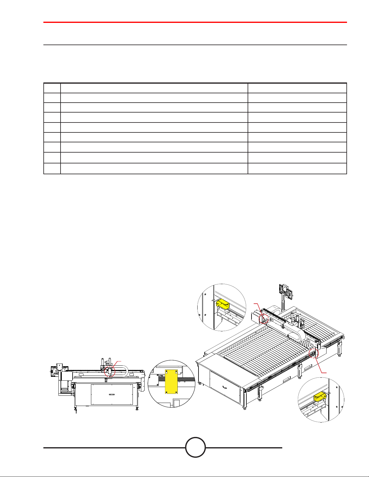
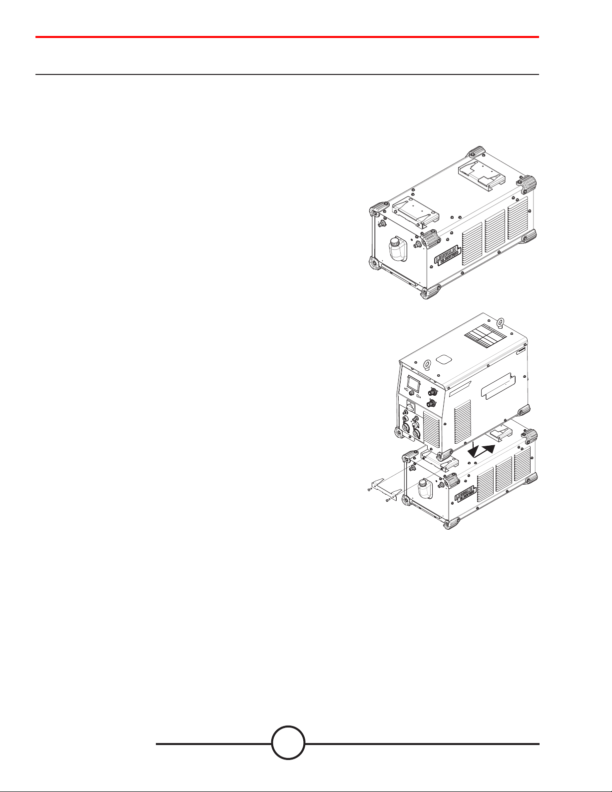
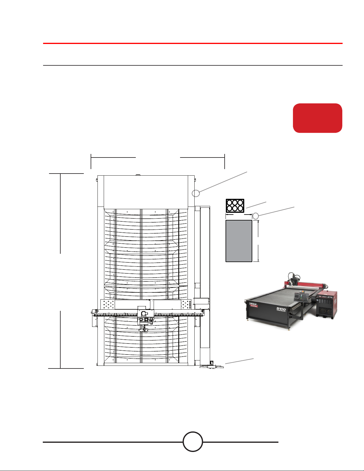
Unpacking your new machine
Your new Torchmate 5100 CNC machine is delivered assembled, but you will need to remove the shipping
material and gantry locks before operation. Verify all items have been shipped without damage before you accept the
order from the shipping company. Notify Lincoln Electric® 775-673-2200 to report any shipping damages. Your machine
was fully tested at the factory, a metal cut sample can be found in the bed of the machine.
Qty. Description Part Number
1 Lincoln Electric Torchmate
1 Lincoln Electric Torchmate
1
Lincoln Electric Torchmate
1
Lincoln Electric Torchmate
1 Lincoln Electric Torchmate
1 Lincoln Electric Torchmate
1
Lincoln Electric Torchmate
1
Lincoln Electric Torchmate
To unpackage your new Torchmate 5100 is simple. Your machine will arrive on a atbed truck and wrapped in plastic.
Use a razor knife to remove the wrap from the machine. Inspect the contents and verify that there is no damage to the
machine or its contents in the bed. If damaged, do not accept the shipment and contact Lincoln Electric Cutting
Systems.
TM
5100 Water Table with FlexCutTM 125 Plasma Unit LECS-5100-125-W0
TM
5100 Water Table with FlexCutTM 200 Plasma Unit LECS-5100-200-W0
TM
5100 Water Table with Spirit® II 275 Plasma Unit
TM
5100 Water Table with Spirit® II 400 Plasma Unit
TM
5100 Down draft with FlexCutTM 125 Plasma Unit LECS-5100-125-D0
TM
5100 Down draft with FlexCutTM 200 Plasma Unit LECS-5100-200-D0
TM
5100 Down draft with Spirit® II 275 Plasma Unit
TM
5100 Down draft with Spirit® II 400 Plasma Unit
LECS-5100-275-W0
LECS-5100-400-W0
LECS-5100-275-D0
LECS-5100-400-D0
The plasma unit, along with all the connection cables will be secured to a separate pallet. To remove the plasma power
supply from the pallet, team lift or forklift the plasma power supply and set aside until the machine is placed in its nal
operational location. The plasma unit will sit on the oor near the cable carrier exit on the monitor side.
A 6,600lb + forklift with 8’+ long forks is required to place the machine in its operational position. Use the forklift access
ports on the machine. Do not lift the machine from the cable carrier side.
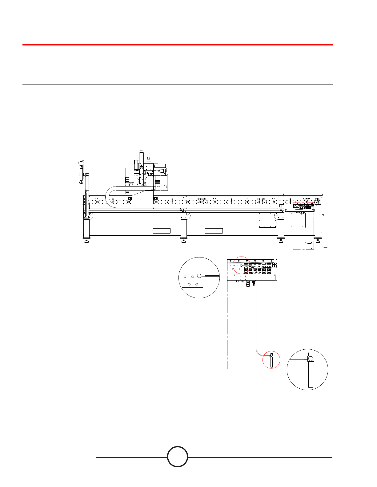
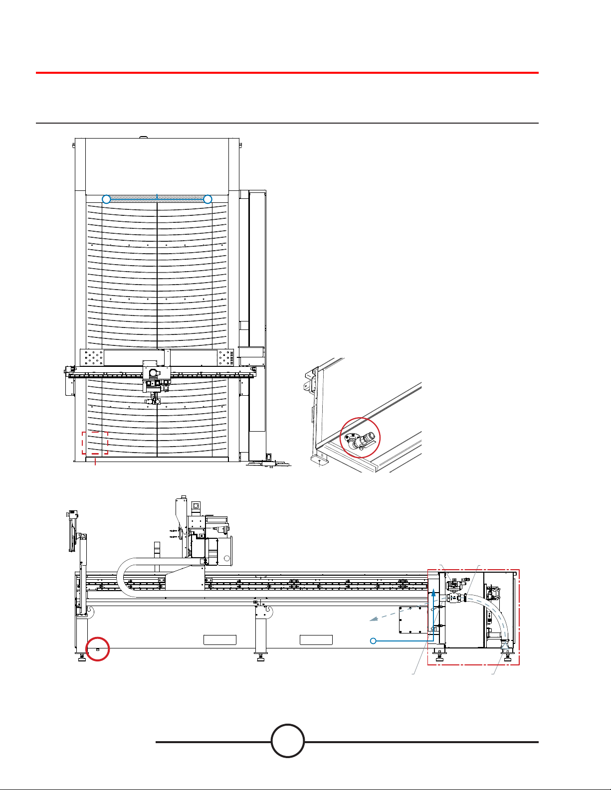
Torchmate 5100 models ship with factory installed gantry
locks. The yellow locking devices MUST BE removed before
the machine can be made operational.
DO NOT REPLACE THE BOLTS FROM THE GANTRY LOCKS
AS THIS WILL CAUSE DIRECT DAMAGE TO THE MACHINE.
Do Not Fork Lift From
Cable Carrier Side Of
Machine!
A
DETAIL A
iii
User Guide
Page 4

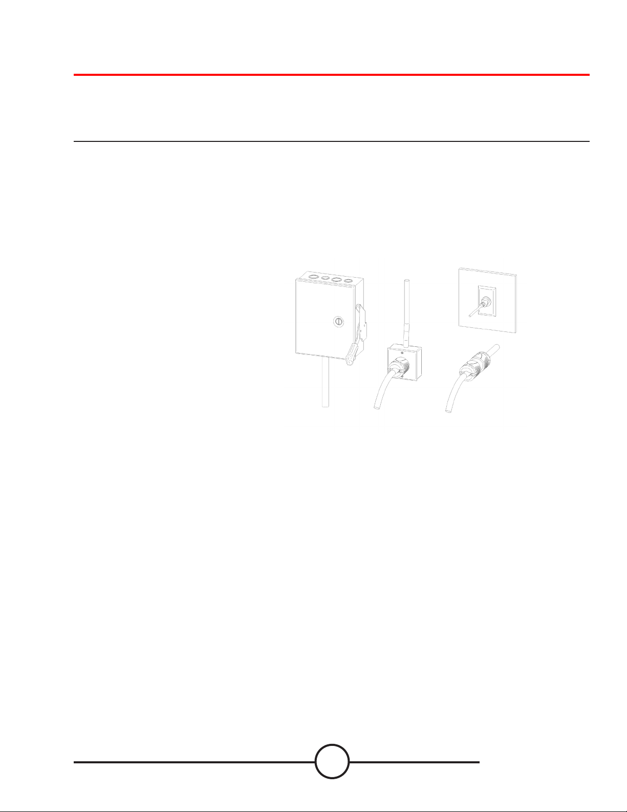
Unpacking your new machine (Leveling Feet)
When placing the machine, you will need to install the adjustable feet into the pads prior to leveling the machine. With
the machine lifted and secured, screw in all of the adjustable feet into each of the pads. DO NOT USE a hydraulic lift to
secure the machine when installing the leveling feet. Screw them halfway into the pads to get the most movement for
leveling. Once the machine is placed, then level the table. When the machine is level, then follow the WATER FILL
process.
Use ALL of the leveling feet to secure and level the table.
Make sure the table does not rock or have any movement once level.
Then the table is ready to be lled with water. (if water table)
Torchmate 5100
iv
Page 5
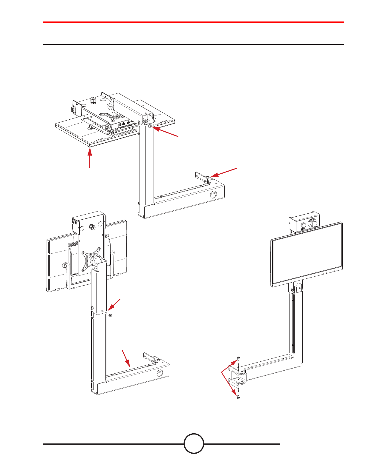
Unpacking your new machine (Monitor Arm Assembly)
4. REINSERT BOLTS
AND SECURE IN PLACE
Unfolding and securing the Monitor Arm Assembly requires a few bolts to be removed and reused to secure the arm in
place.
Remove the bolts that are indicated in the drawing and reuse them to secure the arm
1. Remove the bolt from behind the monitor and
two bolts on the swing bracket.
2. Lift the monitor up and secure with the removed bolt.
3. Grab the arm and swivel it 180 degrees into
place.
4. Re-insert the bolts to secure the arm in place.
2. LIFT MONITOR
1. REMOVE BOLT
1. REMOVE BOLTS 2x,
ONE TOP AND ONE ON BOTTOM
2. REINSTALL BOLT
3. ROTATE ENTIRE MONITOR
ARM 180 DEGREES
v
User Guide
Page 6
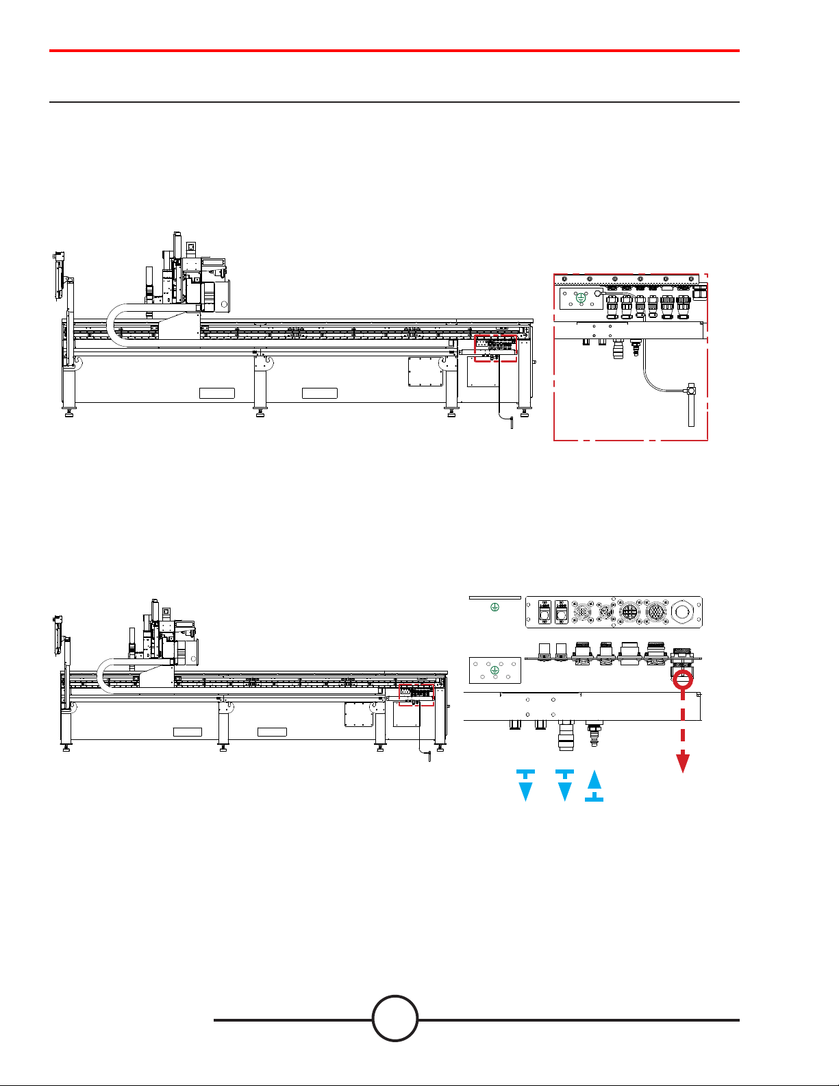
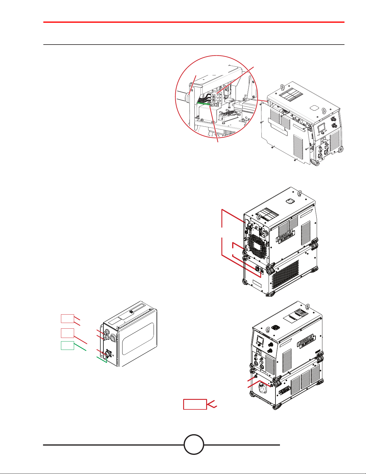
Unpacking your new machine (Electrical Connections)
INPUT
To Plasma
(for accessories)
Internally the 5100 comes pre-wired and ready to run. All systems are test red and disconnected at the facility before
packaging and shipping. For shipping purposes, the plasma power supply is disconnected from the system and will
require a connection to the machine. The table has a single 120v NEMA 5-15P plug that powers the table and computer/
monitor. The plasma power supply chosen requires 3-phase electrical connections along with numerous other connections that are required by your specic power supply to interface with the machine.
All electrical, air, and interface connections
to the machine will be o of the BULKHEAD
Electrical Bulkhead
5100 - Table Power and Air connections:
Attach the supplied 120v 15A plug into a wall outlet. This will power the electronics and table functions.
Star Ground
Star Ground
1/4” OD TUBING
PUSH
CONNECT
ETH 0
EXT. NETWORK
ETH 1
FLEX NET
1/4” QUICK
CONNECT
PLASMA
INTERFACE
P1
1/4” QUICK
CONNECT
P2
PLASMA
ARC VOLATGE
P3
P4
CAN
AUXILARY
INTERFACE
I/O
120v Power Cord
15’, NEMA 5-15p
5100 - Pneumatic Connection:
The 1/4” Industrial Quick Disconnect input on the bulkhead will distribute the air to the plasma power supply along
with table operations. Any accessories or collision sensors will also be provided shop air by tapping into the two
provided output 1/4” Tubing Push-Connects.
POWER
ENTRY
BOTTOM
VIEW
FRONT
VIEW
Torchmate 5100
vi
Page 7
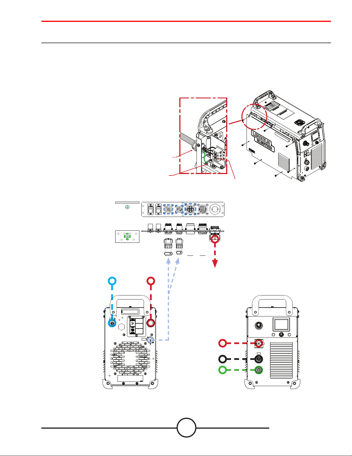
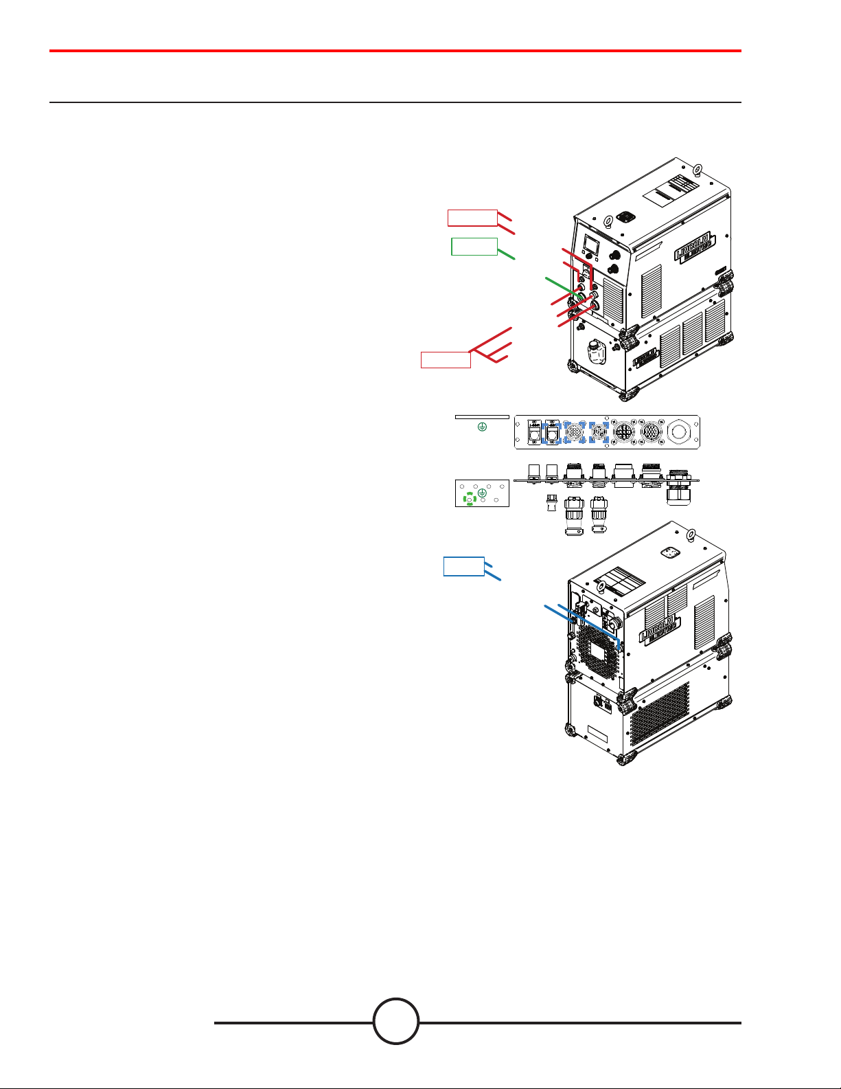
Unpacking your new machine (FlexCut™ 125)
GROUND CONNECTION
CONNECT GROUND LEAD PER LOCAL
AND NATIONAL ELECTRIC CODE
INPUT CORD STRAIN RELIEF
ROUTE INPUT CORD THROUGH RELIEF
AND TWIST NUT TO TIGHTEN
POWER CONNECTION BLOCK
CONNECT EACH PHASE OF A
THREE PHASE CONDUCTOR HERE
FlexCut 125:
FlexCut 125 will have two barrel connectors to attach to the bulkhead. When moving your FlexCut 125, use
team lift or hoist. A 10 ft.(3m) power cord is provided with the FLEXCUT 125. Three Phase Input Only. Connect green lead
to ground per National Electric Code.
Connect black, red and white leads to power.
In all cases, the green or green/yellow grounding wire
must be connected to the grounding pin of the plug,
usually identied by a green screw. Attachment plugs
must comply with the Standard for Attachment Plugs
and Receptacles, UL498.The product is considered
acceptable for use only when an attachment plug as
specied is properly attached to the supply cord.
Air or Gas Inlet (1/4”
Female Quick Connect)
from bulkhead:
Star Ground
Star Ground
3-ph
Main Power
ETH 0
EXT. NETWORK
ETH 1
FLEX NET
P1
PLASMA
INTERFACE
PLASMA
ARC VOLATGE
P3
P2
CAN
INTERFACE
AUXILARY
P4
I/O
120v Connection
CNC Interface
Cable
Main Power
Switch
Torch Lead
Work (ground)
Connection to
Star
POWER
ENTRY
BOTTOM
VIEW
FRONT
VIEW
FlexCut 125
Back
vii
FlexCut 125
Front
User Guide
Page 8
Unpacking your new machine (FlexCut™ 200/FlexCool™ 35)
FlexCut 200 and FlexCool 35:
FlexCut 200 is liquid cooled and is supplied with the FlexCool 35. For complete instructions on the FlexCut 200
and the FlexCool 35 see their corresponding user guides.
Unpacking the FlexCool 35:
The packaging of the cooler is designed to withstand shipping abuse. If any
shipping damage has occurred, contact your certied Lincoln distributor
or service center. When unpacking the unit, avoid thrusting sharp objects
through the carton, which may damage the machine. Below is the recommended procedure for unpacking the cooler:
• Cut and remove banding straps around skid and carton
• Remove carton
• Cut and remove banding straps around skid and cooler
• Remove cooler, literature, and other items
Save the instruction manual and service directory supplied with the
FlexCool 35 for parts orders and future maintenance service.
Mounting the FlexCool 35 underneath the FlexCut 200:
The FlexCool 35 can be mounted underneath the FlexCut 200 machine or by
itself on a at surface.
No power source should ever be installed underneath the FlexCool 35.
Securing the FlexCut 200 to the FlexCool 35:
1. Begin by setting the FlexCool 35 on a hard at surface.
2. Remove the two 7/16” bolts and the locking bracket from the
front mounting bracket
3. Lift the FlexCut 200 and place on top and slightly forward of the
FlexCool 35
4. Carefully guide the FlexCut 200 so that the quick lock feet on the
bottom of the power source slide into the channels of the mount
ing brackets on top of the FlexCool 35. Be sure all 4 feet are within
the channels.
5. Slide the FlexCut 200 all the way back so that it is sitting exactly
overtop of the FlexCool 35. The feet should be all the way at the
back of the channels.
6. Replace the locking bracket into the front mounting bracket of the
FlexCool 35. Torque both 7/16” bolts to 50 in-lbs.
Filling the Coolant Reservoir:
USE ONLY LINCOLN ELECTRIC TORCH COOLANT - BK500695
1.5 gallons of coolant are preloaded into the machine at the facility for live re testing.
Pour .75 gallons (2.84 liters) of coolant into the coolant reservoir ll hole through a funnel.
Use the coolant purge command in the machine UI menus to help prime the system.
While priming, add additional coolant to keep the reservoir full. The cooler is “FULL” when the coolant lies just below the
coolant reservoir opening.
Be certain to replace the reservoir ll cap when the reservoir is full. Operation of the FlexCool 35 without the reservoir
cap can cause unnecessary contamination and could be hazardous to others. See the FlexCool 35 manual for complete
instructions and safety precautions.
Torchmate 5100
viii
Page 9
Unpacking your new machine (FlexCut™ 200/FlexCool™ 35)
The FlexCut 200 does not come with an SO
cord installed for the main power connection.
Use a three-phase supply line. A 1.75 inch (45
Input Cord Strain Relief:
Route input cord through
relief and twist nut to tighten.
mm) diameter access hole for the input supply
is located on the case back.
Connect L1, L2,L3 and ground per connection
diagrams and National Electric Code.
To access the input power connection block,
remove the seven screws and the left case side
of the machine as shown.
Connections between the FlexCut 200 and FlexCool 35:
1. Connect the 115v from the FlexCool 35 to the 115v connection on the back of the FlexCut 200.
2. Connect the ARCLINK cable into the FlexCut 200 to the
FlexCool 35.
3. The two coolant supply lines from the FLEXSTART box will
be coming out the cable carrier. Attach the supply lines to
the FLEXCOOL 35.
4. On the gantry by the FLEXSTART box, remove the zip tie
and connect the two hoses and ARCLINK barrel connector to
the FLEXSTART.
Ground Connection:
Connect Ground Lead per local
and national electrical codes
115 V
AC**
ARC LINK
Power Connection Block:
Connect each phase of a three
phase connector here
FROM
COOLER
COOLANT RETURN
COOLANT SUPPLY
FROM
POWER
SOURCE
TO
STAR
GROUND
ARCLINK
GROUND
FLEXSTART box mounted to gantry on the
5100. Hoses and cables are run into the
cable carrier.
TO
FLEXSTART
ix
COOLANT RETURN
COOLANT SUPPLY
User Guide
Page 10
Unpacking your new machine (FlexCut™ 200/FlexCool™ 35)
Connections between the FlexCut 200 and 5100:
5. From the cable carrier, connect the PLASMA GAS
and SHIELD GAS to the FlexCut 200.
6. Attach the PLASMA connections from the cable
carrier to the NOZZLE, ARC LINK, ELECTRODE.
7. Connect the WORK to the STAR GROUND BLOCK on
the machine.
CABLE CARRIER
STAR GROUND
FROM
CABLE CARRIER
FROM
TO
Star Ground
PLASMA GAS
SHIELD GAS
WORK
NOZZLE
ARC LINK
ELECTRODE
ETH 1
ETH 0
FLEX NET
EXT. NETWORK
PLASMA
INTERFACE
P1
PLASMA
ARC VOLATGE
CAN
INTERFACE
AUXILARY
P4
POWER
ENTRY
I/O
P3
P2
8. Connect the CNC interface cable to the BULKHEAD
P1 and P2.
9. Connect the ETHERNET connector to the back of
the FLEXCUT 200. Attach the other end to the ETH1
port to the Fiber Optic box. Attach the ber optic and
power cable to the converter box.
For full wiring instructions, see the corresponding
manuals for the FlexCut 200 and FlexCool 35.
Star Ground
TO
5100 BULKHEAD
CNC INTERFACE
ETHERNET
Torchmate 5100
x
Page 11

Technical Support | On-Site Service
Lincoln Electric Cutting Systems provides numerous technical support opportunities with the purchase of your new
Torchmate 5100 CNC cutting machine. The following is a brief outline of available options. On-site visits are available at
an additional cost call 775-673-2200 for additional information.
• Phone Support
Phone support is available Monday – Friday 7:00 am-4:00 pm PST. Lincoln Electric will make every eort to handle phone calls promply. Due to the nature of machine diagnoses and the varied
capabilities of machine operators we cannot guarantee hold wait times for phone-in technical
support.
Technical support includes, machine assembly/set-up, troubleshooting, conguration, and quality
related issues. Operational or CAD training is not included in phone technical support.
• Email
Lincoln Electric will return emails to the support@Torchmate.com email address within 24 hours
Monday-Friday
• Webinars and LiveStream
Lincoln Electric provides live webinars from time to time to assist customers in the optimization and
operation of CNC systems. Please subscribe to our newsletter for dates and times.
http://torchmate.com/webinars
• Torchmate Training Seminars
Lincoln Electric provides a number of training opportunities at our Reno, Nevada campus and at
select Regional locations. Please call 775-673-2200 for details or visit
http://torchmate.com/seminars
• Torchmate Online Training
Lincoln Electric maintains a number of operational training resources at
http://torchmate.com/training
• Torchmate YouTube Channel:
Lincoln Electric provides a wide selection of how to tutorials on our YouTube page.
https://www.youtube.com/user/torchmatedotcom
xi
User Guide
Page 12

Statement of Warranty
30 Day guarantee
Warranty
If Buyer is not satised with the performance of the Goods within 30 days from the
date the Goods were shipped from the Seller, Buyer may return the Goods in the
original carton(s) for a full refund less Shipping, Handling, Damages and Freight
Charges. All sales become nal after this 30 day period. Buyer should determine the
satisfactory performance of the Goods by using the software, and inspecting and
bench running the motors and/or accessory items. Any items to be returned for full
refund must be in new, unused (except for bench testing), and saleable condition at
the sole determination of the Seller. Items that, in the Seller’s judgment, have been
used or modied in any way, or kits that have been partially or fully completed will
be subject to a restocking fee to be determined by the Seller. A return merchandise
authorization number (RMA) must be obtained by the customer prior to any return.
Shipments of returned items not marked with a valid RMA will be refused.
Electronics and motors are warranted by their manufacturer to the original purchaser
for 12 months from the date of Torchmate, Inc.’s sale invoice. Mechanical components
are standard industrial parts and are not warranted except by their respective
manufacturers. If any of the warranted items are found by Seller to be defective, such
Goods will, at Seller’s option, be replaced or repaired at Seller’s cost. No defective
goods are to be returned without written authorization of seller. The sole purpose
of the stipulated exclusive remedy shall be to provide the Buyer with free repair and
replacement of defective Goods in the manner provided herein. This exclusive remedy
shall not be deemed to have failed of its essential purpose so long as the Seller is
willing and able to repair or replace defective Goods in the prescribed manner. The
foregoing warranty is in lieu of all other warranties, express or implied, including
those of merchantability or tness for any purpose not expressly set forth herein. No
armation of Seller, by words or action, other than as set forth in this Section shall
constitute a warranty. Seller’s warranty does not apply to any Goods which have been
subjected to misuse, mishandling, misapplication, neglect (including but not limited
to improper maintenance), accident, improper installation, modication (including
by not limited to use of unauthorized parts or attachments), or adjustment or repair
performed by anyone other than Seller or one of Seller’s authorized agents. When
returning products to Seller packaging must be adequate or all warranty is null and
void. Buyer will pay for the cost of Shipping to and from the Seller for all warranty
repairs.
Any claim by Buyer with reference to the Goods sold hereunder shall be deemed waived
by the Buyer unless submitted in writing to seller within the earlier of (i) thirty (30)
days following the date Buyer discovered or by reasonable inspection should have
discovered, any claimed breach of foregoing warranty, or (ii) 12 months following the
date of shipment. Any cause of action for breach of the foregoing warranty shall be
brought within one year from the date the alleged breach was discovered or should
have been discovered, whichever occurs rst.
Torchmate 5100
xii
Page 13

Statement of Warranty (cont.)
Seller’s liability (whether under the theories of breach of contract or warranty,
negligence, or strict liability) for its Goods shall be limited to repairing or replacing
Goods found by Seller to be defective, or at Seller’s option, to refunding the purchase
price of such Goods or parts thereof.
In no event shall seller be liable for consequential damages arising out of or in
connection with this agreement, including without limitation, breach of any obligation
imposed on seller hereunder. Consequential damages shall include without limitation,
loss of use, income or prot, or loss sustained as the result of injury (including death)
to any person, or loss of or damage to property (including without limitation property
handled or processed by the use of the goods). Buyer shall indemnify seller against all
liability, cost or expense which may be sustained by seller on account of any such loss,
damage, or injury.
Upon buyer’s receipt of shipment, Buyer shall immediately inspect the Goods. Unless
Buyer provides Seller with written notice of any claim for shortage, overcharge, or
damage of Goods within ten (10) days from invoice date, such Goods shall be deemed
nally inspected, checked and accepted by Buyer and no allowances shall be made
thereafter. In absence of shipping and packaging instructions, Seller shall use its own
discretion in the choice of carrier and method of packing. Seller shall not be responsible
for insuring shipments unless specically requested by Buyer and any insurance or
special packaging so requested shall be at Buyer’s expense and valuation.
Title to any Goods sold and risk of loss of such Goods passes to Buyer upon delivery by
Seller to carrier and any claims for losses or damages shall be made by Buyer directly
with carrier.
A. In addition to the rights and remedies conferred upon Seller by law, Seller shall not
be required to proceed with the performance of any order or contract if the Buyer
is in default in the performance of any order or contract with Seller, and in case
of doubt as to Buyer’s nancial responsibility, shipments under this order may be
suspended.
B. No delay or omission by Seller in exercising any right or remedy provided for herein
shall constitute a waiver of such right or remedy and shall not be constituted as a
bar to or a waiver of any such right or remedy on any future occasion.
C. The sale of Goods shall be governed by the laws of the State of Maryland. Seller
agrees to comply with all applicable laws of the United States.
D. The purchasers of products from Lincoln Electric Cutting Systems are responsible
to dispose of consumables, uids and machinery at the end of the life cycle in
accordance with federal and local regulations.
The invalidity or unenforceability of any one or more phrases, sentences, or sections
shall not aect the validity or enforceability of the remaining portions of this
Agreement.
Limitation of
liability
Disclaimer of
consequential
damages
Acceptance and transportation
Title and
risk of loss
General
conditions
Severability
xiii
User Guide
Page 14

Safety First
Torchmate and Lincoln Electric Cutting Systems equipment is designed and built with safety in mind. Safe
operation requires that the user follow proper installation, training, and safe operating procedures.
THIS MACHINE CREATES ELECTRO-MAGNETIC FIELDS DURING OPERATION
WARNING
PROTECT YOURSELF AND OTHERS FROM POSSIBLE SERIOUS INJURY OR DEATH.
DO NOT INSTALL,
OPERATE, OR REPAIR
THIS EQUIPMENT
WITHOUT READING
THE SAFETY WARNINGS
CONTAINED THROUGHOUT THIS MANUAL.
Think before you act—
and be careful.
While Operating the machine.
• WEAR CORRECT EYE, EAR & BODY PROTECTION
• PROTECT your eyes and face with welding helmet properly tted and with proper hade rating of lter plate (See
ANSI Z49.1).
• PROTECT your body from welding spatter and arc ash with protective clothing including woolen clothing, ameproof apron and gloves, leather leggings, and high boots.
• PROTECT others from splatter, ash, and glare with protective screens or barriers.
• WHEN OPERATING THIS EQUIPMENT, wear hearing protection.
• BE SURE protective equipment is in good condition.
• Provide adequate lighting to the area around the machine appriopriate for all the tasks being completed.
• Wear safety glasses in work area AT ALL TIMES.
• Do not climb on machine. It is not intended as a ladder or to support anything but the intended use of metal cutting. Climbing onto the machine could result in a fall that can result in injury or death.
KEEP CHILDREN AWAY.
IF YOU WEAR A PACEMAKER, YOU SHOULD CONSULT WITH YOUR
DOCTOR BEFORE OPERATING.
Read and understand the following safety highlights. For additional safety information it
is strongly recommended that you acquire a copy of “Lincoln Electric E205 ‘Arc Welding
Safety’”as well as “Safety in Welding & Cutting - ANSI Standard Z49.1” from the American
Welding Society, P.O. Box 351040, Miami, Florida 33135 or CSA Standard W117.2.
BE SURE THAT ALL INSTALLATION, OPERATION, MAINTENANCE, AND REPAIR
PROCEDURES ARE PERFORMED ONLY BY QUALIFIED INDIVIDUALS
ELECTRIC SHOCK can kill.
• The electrode and work (or ground) circuits are electrically “hot” when the power source is on. Do not touch these
“hot” parts with your bare skin or wet clothing. Wear dry, hole-free gloves to insulate hands.
• Disconnect the power source before performing any service or repairs. When the power source is operating,
voltages in excess of 250 volts are produced. This creates the potential for serious electrical shock - possibly even
fatal.
• Insulate yourself from work and ground using dry insulation. Wear dry gloves and clothing. Take extra care when
the work place is moist or damp.
• Always be sure the work cable makes a good electrical connection with the metal being cut or gouged. The
connection should be as close as possible to the area being cut or gouged.
• Ground the work or metal to be cut or gouged to a good electrical (earth) ground.
• Maintain the plasma torch, cable and work clamp in good, safe operating condition. Repair or replace all worn or
damaged parts. Replace damaged insulation.
• Never dip the torch in water for cooling or plasma cut or gouge in or under water.
• When working above oor level, protect yourself from a fall should you get a shock.
• Operate the pilot arc with caution. The pilot arc is capable of burning the operator, others or even piercing safety
clothing.
1
User Guide
Page 15

FUMES AND GASES can be dangerous.
• Plasma cutting or gouging may produce fumes and gases hazardous to your health. Avoid breathing these fumes
and gases. When cutting or gouging, keep your head out of the fumes. Use enough ventilation and/or exhaust at the
arc to keep fumes and gases away from the breathing zone and general area.
• Use an air-supplied respirator if ventilation is not adequate to remove all fumes and gases.
• When plasma cutting or gouging on lead or cadmium plated steel and other metals or coatings which produce toxic
fumes, keep exposure as low as possible and within applicable limits such as the OSHA PEL and ACGIH TLV limits,
using local exhaust or mechanical ventilation. In conned spaces or in some circumstances a respirator will be
required.
• Additional precautions are also required when cutting (zinc) galvanized steel or materials containing or coated with
any of the following:
Antimony Beryllium Cobalt Manganese Selenium
Arsenic Cadmium Copper Mercury Silver
Barium Chromium Lead Nickel Vanadium
• The operation of plasma cutting or gouging fume control equipment is aected by various factors including proper
use and positioning of the equipment, maintenance of the equipment, and the specic procedure and application
involved. Worker exposure levels should be assessed by a qualied individual, such as an industrial hygienist, upon
installation and periodically thereafter to be certain levels are within applicable exposure limits, such as the OSHA
PEL and ACGIH TLV. For information on how to test for fumes and gases in your work place, refer to publications
section of this manual.
• Do not use plasma cutting or gouging equipment in locations near chlorinated hydrocarbon vapors coming from
degreasing, cleaning or spraying operations. The ultraviolet rays from the arc can react with solvent vapors to form
phosgene, a highly toxic gas, and other irritating products. Remove all sources of these vapors.
• Materials containing chromium may release hexavalent chromium compounds during plasma cutting and other hot
work.
• Hexavalent chromium compounds are on the IARC list as posing a lung cancer risk to humans. Use adequate ventilation to avoid overexposures.
• Gases used for plasma cutting and gouging can displace air and cause injury or death. Always use enough
ventilation, especially in conned areas, to insure breathing air is safe.
• Read and understand the manufacturer’s instructions for this equipment and follow your employer’s safety
practices.
• This product, when used for cutting, produces fumes or gases which contain chemicals known to the State of
California to cause birth defects
• Fumes and gases from hot work and dust created by routing, sawing, grinding, drilling, and other construction
activities contains chemicals known to cause cancer, birth defects or other reproductive harm. Avoid prolonged contact with this dust. Wear protective clothing and wash exposed areas with soap and water. Avoid dust to get into
your mouth, eyes, or lay on the skin as this may promote or result in the absorption of harmful chemicals.
Some examples of these chemicals are:
• Lead from lead-based paint.
• Crystalline silica from bricks and cement and other masonry products.
• Arsenic and chromium from chemically-treated lumber (CCA).
Your risk from these exposures varies, depending on the nature and frequency of this type of work. To revent your exposure to these chemicals: Use local exhaust ventilation and/or work in a well ventilated area, and work with approved
safety equipment, including respiratory protection that is properly selected in accordance with the contaminants, and
their concentrations present in the work environment.
Torchmate 5100
2
Page 16

ARC RAYS can burn.
• Plasma Arc Rays can injure your eyes and/or burn your skin. The plasma arc process produces very bright ultraviolet
and infrared rays. These will damage your eyes and burn your skin if you are not properly protected.
• Use safety glasses and a shield with the proper lter and cover plates to protect your eyes from sparks and the rays
of the arc when performing or observing plasma arc cutting or gouging. Glasses, head-shield, and lter lens should
conform to ANSI Z87. I standards.
Use suitable clothing including gloves made from durable ame-resistant material to protect your skin and that of
your helpers from the arc rays.
• Protect other nearby personnel with suitable non-ammable screening and warn them about the hazards of the
activity taking place, and the precautions they must take.
• According to IARC, ultraviolet radiation from
welding causes ocular melanoma. IARC identies
gouging, brazing, carbon arc or plasma arc cutting, and
soldering as processes closely related to welding
Cutting ame and sparks can cause FIRE OR EXPLOSION.
Arc Current Minimum
Shade No.
Less than 20A 4 4
20A-40A 5 5
40A-60A 6 6
60A-300A 8 9
300A-400A 9 12
400A-800A 10 14
Suggested
Shade No.
• Read and follow NFPA 51B “ Standard for Prevention During Welding, Cutting and Other Hot Work”, available from
NFPA, 1 Batterymarch Park,PO box 9101, Quincy, Ma 022690-9101.
• Fire and explosion can be caused by hot slag, sparks, oxygen fueled cutting ame, or the plasma arc.
• Have a re extinguisher readily available. Provide a re watch when working in an area where re hazards may
exist.
• When not cutting or gouging, make certain no part of the electrode circuit is touching the work or ground.
Accidental contact can cause overheating and create a re hazard.
• Be sure there are no combustible or ammable materials in the workplace. Any material that cannot be removed
must be adequately protected as to avoid any potential for contact with ames, sparks or spatter.
• Sparks and hot materials from cutting or gouging can easily go through small cracks and openings to adjacent
areas.
• Avoid cutting or gouging near hydraulic lines.
• Do not cut or gouge tanks, drums or containers until the proper steps have been taken to insure that such
procedures will not cause ammable or toxic vapors from substances inside. They can cause an explosion even
though they have been “cleaned.” For information purchase “Recommended Safe Practices for the Preparation for
Welding and Cutting of Containers and Piping That Have Held Hazardous Substances”, AWS F4.1 from the American
Welding Society (see address above).
• Vent hollow castings or containers before heating, cutting or gouging. They may explode.
• Do not add fuel to engine driven equipment near an area where plasma cutting or gouging is being done.
• Connect the work cable to the work as close to the cutting or gouging area as practical. Work cables connected
to the building framework or other locations away from the cutting or gouging area increase the possibility of
the current passing through lifting chains, crane cables or other alternate circuits. This can create re hazards or
overheat lifting chains or cables until they fail.
• Hydrogen gas may be formed and trapped under aluminum work pieces when they are cut underwater or while
using a water table. DO NOT cut aluminum alloys underwater or on a water table unless the hydrogen gas can be
eliminated or dissipated. Trapped hydrogen gas that is ignited will cause an explosion.
3
User Guide
Page 17

CYLINDER may EXPLODE if damaged.
• Use only compressed gas cylinders containing the correct gas for the process used and properly operating
regulators designed for the gas and pressure used. All hoses, ttings, etc. should be suitable for the application and
maintained in good condition.
• Always keep cylinders in an upright position securely chained to an undercarriage or xed support.
• Cylinders should be located: • Away from areas where they may be struck or subjected to physical damage. • A safe
distance from plasma cutting or gouging, arc welding operations and any other source of heat, sparks, or ame.
• Never allow any part of the electrode, torch or any other electrically “hot” parts to touch a cylinder.
• Keep your head and face away from the cylinder valve outlet when opening the cylinder valve.
• Valve protection caps should always be in place and hand tight except when the cylinder is in use or connected for
use.
• Read and follow the instructions on compressed gas cylinders, associated equipment, and CGA publication P-l,
“Precautions for Safe Handling of Compressed Gases in Cylinders,”available from the Compressed Gas Association
1235 Jeerson Davis Highway, Arlington, VA 22202.
FOR ELECTRICALLY powered equipment.
• Turn o input power using the disconnect switch at the fuse box before working on the equipment.
• Install equipment in accordance with the U.S. National Electrical Code, all local codes and the manufacturer’s recommendations.
• Ground the equipment in accordance with the U.S. National Electrical Code and the manufacturer’s
recommendations.
PLASMA ARC can injure.
• Keep your body away from nozzle and plasma arc.
• Operate the pilot arc with caution. The pilot arc is capable of burning the operator, others or even piercing safety
clothing.
ELECTRIC AND MAGNETIC FIELDS may be dangerous
• Electric current owing through any conductor causes localized Electric and Magnetic Fields (EMF). Cutting or gouging current creates EMF elds around torch cables and cutting machines.
• EMF elds may interfere with some pacemakers or other medical implant devices, so operators who have such a
device should consult their physician and the device manufacturor before cutting or gouging.
• Exposure to EMF elds during cutting or gouging may have other health eects which are now not known.
• All operators should use the following procedures in order to minimize exposure to EMF elds from the cutting or
gouging circuit:
• Route the torch and work cables together - Secure them with tape when possible.
• Never coil the torch cable around your body.
• Do not place your body between the torch and work cables. If the torch cable is on your right side, the work
cable should also be on your right side.
• Connect the work cable to the workpiece as close as possible to the area being cut or gouged.
• Do not work next to cutting power source.
For more information on electromagnetic interference please visit
Torchmate 5100
http://torchmate.com/white-papers/EMI-Reduction
4
Page 18

Table Specications
Input Power
• 120V / 1Ph / 15A / 60Hz (table and computer)
• 380-600V / 3Ph / 50-60Hz (Plasma Power Supply specic)
Machine Size
• 60˝ x 120” (1524mm x 3048mm) Cutting Area
• 113.5˝ x 167” (2895.6mm x 4241.8mm) Footprint
Traverse Speed
• 1,500 ipm (0.635 mps)
Cut Speed
• Up to 1500 ipm
Plate Capacity
• Holds Up To 4” (102mm) 5’x10’ (1524mm x 3048mm) Mild Steel
Weight
• 6,600 lbs (
Operating Temperature
• 32-104° Farenheit (0-40° Celcius)
Motors
• Servo Motors Fitted with Rotary Glass Encoders
Drive System
• Helical Gear Rack and Hardened Pinion with Lubrication
System
Linear Guidance
• Prole Linear Rail
Height Control
• Ohmic Sensing
• Automatic Torch Height Control
• 6.75” Z-axis Travel
Bevel Capabilities
• +/-45° Rotation (dependent on material thickness and power
supply conguration)
Software
• Easy-To-Use Lincoln Electric User Interface
• CAM with Irregular Part Nesting
• Popular Shape Library
Fume Extraction (Optional Accessory)
• 61,801 ft3/hr or 1,750 m3/hr minimum
• Automatic Filter Cleaning, Pressure Controlled
Downdraft Conguration
• Multiple Zones Controlled By Motion Controller
Safety
• Dual-Channel Safety System Supporting Emergency Stop
Switch
• Safety System Extended To External Peripherals
• External Drive Power On Switch
Machine Construction
• Fabricated Steel Frame with Powder Coated Finish
Acceleration Rate
• 0.08g (0.06g Bevel)
Warranty
• *1 Year Warranty
Deceleration Rate
• 0.08g (0.06g Bevel)
TORCHMATE 5100 CNC PLASMA SYSTEMS FC 125 FC 200 SP 275 SP 400
PRODUCTION CUTTING CAPACITY
Mild Steel 1” (25mm) 1.25” 1.5” (38mm) 2” (50mm)
Stainless Steel 3/4”(20mm) 3/4”(20mm) 1” (25mm) 1.5” (38mm)
Aluminum 5/8”(16mm) 3/4”(20mm) 3/4” (20mm) 1.5” (38mm)
CUTTING SPEED @ RATED OUTPUT CURRENT
1/4” MS 210 ipm @125A 200 ipm @200A 230 ipm @200A 230 ipm @ 200A
1/2” MS 88 ipm @125A 110 ipm @200A 125 ipm @ 275A 160 ipm @ 400A
1” MS 32 ipm @125A 40 ipm @200A 65 ipm @275A 85 ipm @ 400A
PROCESS AMPS 20A - 125A 15A - 200A 30A - 275A 30A - 400A
CUTTING GAS
Mild Steel Air / Air Air / Air Oxygen / Air Oxygen / Air Oxygen / Oxygen
Stainless Steel Air / Air Nitrogen Air / Air Nitrogen Air / Air - Nitrogen H17 / Nitrogen Nitrogen / Air
Aluminum Air / Air Air / Air Air / Nitrogen Nitrogen Air
INPUT VOLTAGE 380/400/415V3Ph50/60Hz 380/460/575V3Ph50/60Hz 380V 3Ph 50/60Hz | 400V 3Ph 50/60 Hz
460V 3Ph 50/60Hz 400V3Ph 50Hz (CE) 415V 3Ph 50/60Hz | 440V 3Ph 50/60Hz
575V 3Ph 50/60Hz 480V 3Ph 50/60Hz | 600V 3Ph 50/60 Hz
5
User Guide
Page 19
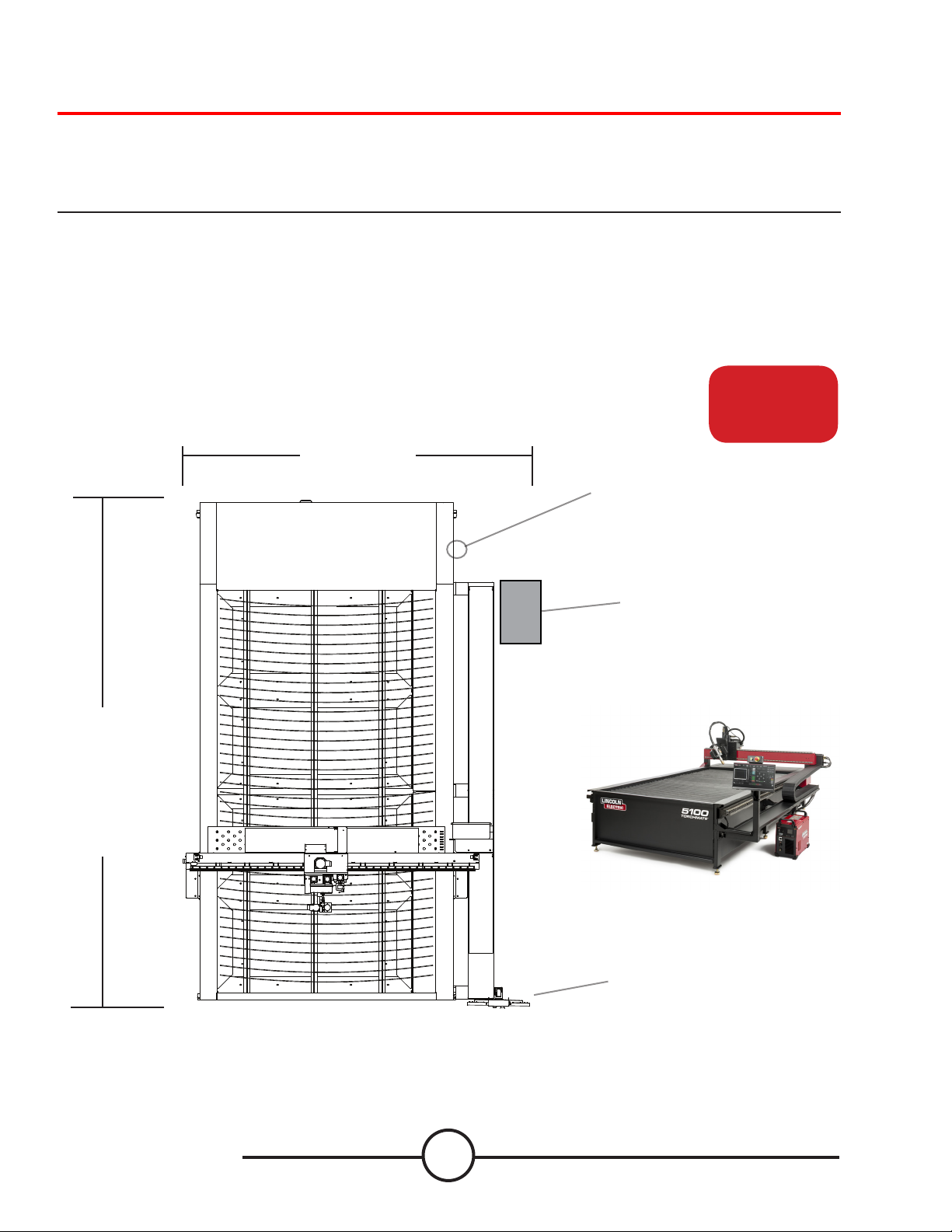
Site Preparation
When installing a Lincoln Electric CNC Cutting System in your shop, there are many factors that will inuence the
tential productivity, ease of use of the machine and the safety of the operator. The main factors to prepare for include
the physical layout and placement of the machine in the shop, the availability of power, an EMI ground, compressed air
and other gases, and ventilation.
• When preparing to install the Lincoln Electric CNC Cutting System, provide sucient space. Three feet of work
space should be maintained at the front of machine
• Forklift load material opposite the cable carrier only. Utilize the back of the machine to park the gantry while
loading material.
• A dedicated earth ground must be provided and should be installed in a manner to reduce trip hazard.
po-
5100
5100
113.25”
15’ Power Cord, NEMA 5-15P
Air Supply
Earth Ground
Provided by Other
FlexCut 125/200
Plasma
Machine
within 10’ of cable
carrier
167”
Load From
This Side
Torchmate 5100
Operator
Console
MAINTAIN WORK AREA
6
Page 20
Site Preparation (HD)
Burny Kaliburn Spirit II power supplies have a larger power box and a gas box. The placement of these products need to
be moved to the cable carrier side within 6’ of the end of the cable chain.
5100 HD
167”
Load From
This Side
113.25”
15’ Power Cord, NEMA 5-15P
Air Supply
Earth Ground
Provided by Other
Gases
30.0
Burny
Spirit 2
Power
Supply
Locate power supply
within 6’ of table cable
chain. Automatic Gas
43.0
Console should be kept
within 2’ of power
supply.
3-phase
Power Supply
Air Supply
Provided by Customer
MAINTAIN WORK AREA
Operator
Console
7
User Guide
Page 21
Grounding Your Machine
Proper grounding must be provided to ensure personnel safety and to suppress high frequency noise. The foundation of
good grounding is an eective earth ground rod. A star ground point connects to the rod with a short, heavy conductor.
A simple copper clad steel rod can be driven into the ground to create a Grounding Rod. A ground rod must be installed.
Consult with a qualied electrical technician to verify your system grounding.
Use 6 AWG Stranded Wire to connect the Star Ground on the table to the customer supplied dedicated earth ground.
For proper operation of your CNC cutting tables you are required to run a 6 AWG cable from the “star” ground to a
dedicated earth-ground rod
Ground rod installations are covered by NEC Section 250.
Place the plasma unit on the appropriate location.
Re-install the power lead and the table ground into
the plasma power supply.
The FlexCut plasma unit is shipped with a factory
ground attached to the star ground. In addition, a
work ground is attached to the star ground to connect
to your material to be cut. If the work piece is painted
or dirty it may be necessary to expose the bare metal
to make a good electrical connection.
Earth Ground Rod is not included with machine
A
STAR GROUND
DETAIL A
GROUND ROD
Torchmate 5100
8
Page 22
Power/Air/Water Requirements and Installation (non-HD)
Please refer to the FlexCut/Spirit II operators manual for a complete installation and operation guidelines. Only a qualied electrician should connect the input leads to the Torchmate 5100 CNC unit and FlexCut/Spirit II Plasma unit. Connections should be made in accordance with all local and national electrical codes. Failure to do so may result in bodily
injury or death.
The FlexCut 125/200 is rated for 380 VAC through 575 VAC input voltage, three phase only and 50 or 60 Hz. Before
connecting the machine to power, be sure the input supply voltage, phase and frequency all match those listed on the
machine rating plate.
The Burny Kaliburn Spirit II plasma cutters are manufactured to the customer’s power availability.
The power supply cord is supplied on the FlexCut 125 without an attachment plug to accommodate three phase installations of being hard wired to a disconnect or for a wall plug. FC200/Spirit II do not include SO cord for connection to
customers power and will need to have the appropriate cable connected per electrical requirements.
Warning:
The FlexCut on/o switch is not
intended as a service disconnect
for this equipment. Only a
qualied electrician should
connect the input leads to the
Torchmate 5100.
120v to Machine
To Plasma Power Supply
The Torchmate 5100 CNC machine requires a clean, dry, oil-free compressed air. A high pressure regulator MUST be used
with a compressor or high pressure cylinder.
Supply pressure must be between 87-110 psi (6-7.6 bar) with ow rated rates of at least 300 SCFH or 140 SLPM.
AIR SUPPLY PRESSURE SHOULD NEVER EXCEED 130 PSI OR DAMAGE TO THE MACHINE MAY OCCUR!
A standard nominal 5 micron in-line lter is recommended, but for optimal performance, select a pre-lter with
a 3 micron absolute rating. Air must be supplied to the plasma with 3/8” inside diameter tubing and 1/4 NPT quick
disconnect coupler. Air lines should be run as to not create a trip hazard.
Water should be installed in the table before operation. Operators are encouraged to use a readily available
anti-corrosive water additive designed for use in CNC plasma water tables.
Water Capacity: 428 gallons (1620 liters)
9
User Guide
Page 23
Slats inside the cutting bed.
The 5100 WT/DD has an array of slats inside the cutting area. These slats hold your material level for cutting. They are
considered a “consumable” item and will need to get replaced on a regular schedule.
• Inside the table sit an array of 69.625” x 3” x 3/16” (4.7625mm) thickness slats that support the material
being cut. After repeated cutting, generally after a year or so of normal cutting time, you will need to
replace the slats. Perform the replacement when the slats can no longer support the material properly or
the build up is hindering the plate from being at.
• The center slat support is oset, to create an ARC of the slats. This makes the slats less prone to getting
damaged in straight cuts, along with keeping the material from moving during cutting.
• The slats can be used on one side and ipped over to increase usage time on one set of slats.
Torchmate 5100
10
Page 24
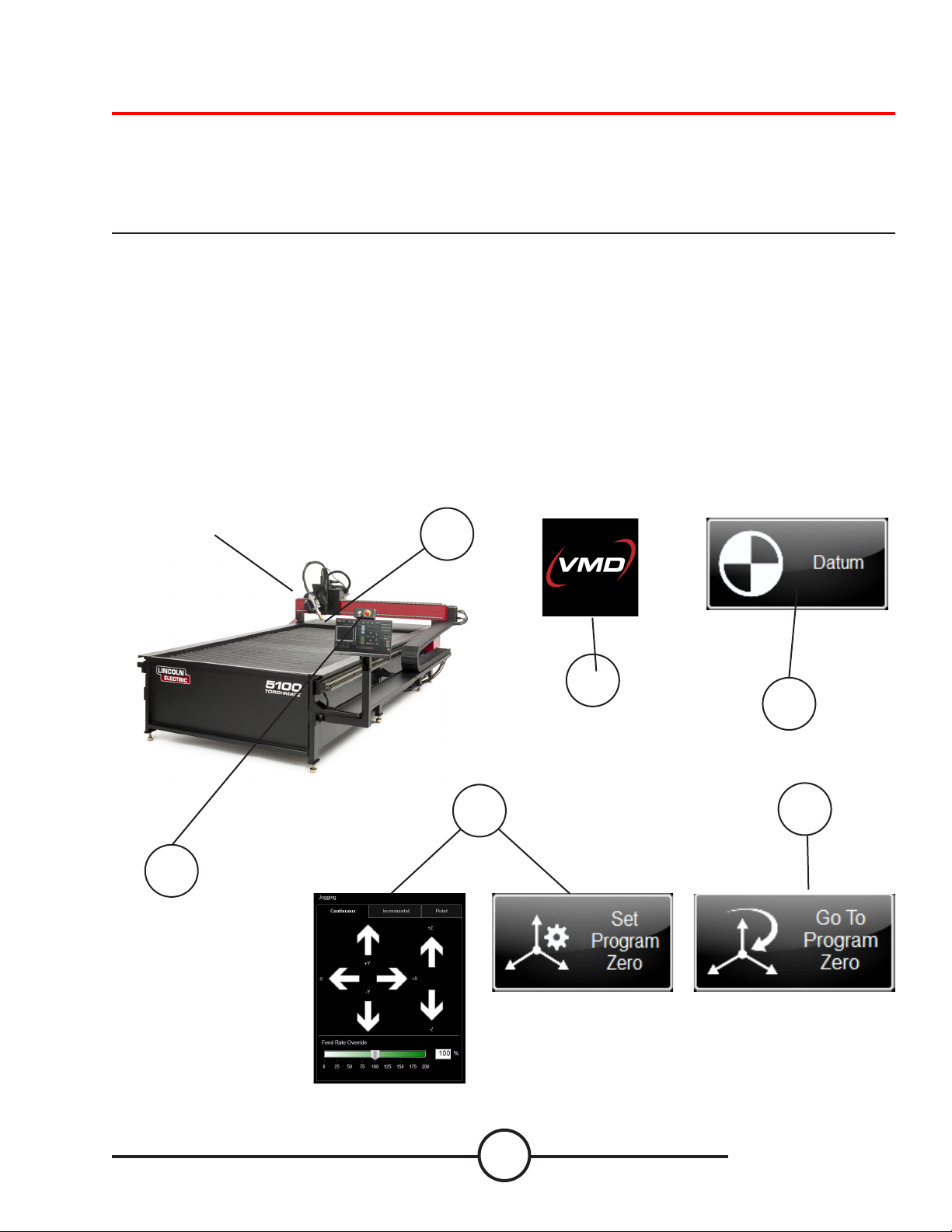
Powering up the Torchmate 5100
To power up your Torchmate 5100 CNC machine, the following items need to be powered up; Machine and Plasma Unit.
The machine will power the controller, computer, and touchscreen. The switch is located on the backside of the machine.
Once switched on, the computer and all the electronics will power up. The power switch for the plasma power supply
is located on the front of the unit. The complete user guide is available as an embedded le in the VMD. Use the button
with the question mark to access this le.
1. Power up the machine by using the toggle switch. (back left of the machine)
2. The VMD Application will auto start with the computer, wait for control panel to load (run.wap)
3. Verify the EMERGENCY STOP(s) are disengaged by turning the RED EMERGENCY STOP button clockwise. One on the
non-cable carrier side of the gantry and one above the monitor.
4. Press the GREEN BUTTON above the Operators Console. (This will power the motors)
5. Press DATUM. (Machine will seek back left corner)
6. Go to the plasma torch head to check and evaluate the consumables. Turn the plasma power supply on and set
the appropriate amperage for the consumables and the material you will be cutting. Cut charts are available in the FlexCut manual. Verify air pressure is correct per manual.
7. Jog the torch to the lower left corner of the material you are going to cut. Press SET PROGRAM ZERO.
8. Press GO TO PROGRAM ZERO. The head should return to the top of the lifter.
Back
Left
Corner
1
3, 4
To JOG machine press
and swipe your nger in
the direction you wish
to JOG.
2
5
7 8
11
User Guide
Page 25
Water Table Operation
Table Drain
The 5100 in Water Table conguration, the water level is controlled by the HMI to raise and lower the machine. The
button RAISE switches a valve to use compressed air to “push” the water to the cutting bed. While pressing LOWER
releases the air from the lower chamber.
The water table is controlled by the HMI.
When you press RAISE WATER, compressed air is
FILL / DRAIN
pushed into the lower chamber.
This “pushes” the water up into the cutting table.
When you press LOWER WATER, the ball valve will
OPEN, releasing the compressed air from the bottom
chamber. This allows the upper chamber to drain the
water into the lower chamber.
• To completely DRAIN your table, use the 2”
QC ball valve in the FRONT LEFT of the table.
Table Drain
Torchmate 5100
12
Table Drain
Air IN
Water UP
WATER TABLE
LOWER CHAMBER
BALL VALVE
OVER FLOW DRAIN
(DRAINS TO FLOOR)
OVERFLOW TUBE
Page 26

Filling the Water Table
The 5100 has an automated water level feature that is controlled on the RUN panel. There is a process that needs to be
followed to properly ll the table to allow proper operation. Connect your air supply to the air inlet on the machine to
proceed.
1. Press LOG ON. Select ADMIN (password 1234). Press OK
2. MACHINE SETTINGS will open. Press the WATER FILL tab.
2.a] If the MACHINE SETTINGS window does not open, in the upper left corner press MAIN
MENU. In the SELECT A PANEL window left click on CONFIGURATION.wap. Press OK, and
MACHINE SETTINGS panel will open.
13
User Guide
Page 27

Filling the Water Table
3. Press the EXHAUST button. This opens the external exhaust vent to allow the air to transfer out of the
empty water tank while the water lls up.
4. Start to ll the table with water. Once the internal tank lls past 2” in the tank, the LOW
WATER indicator will no longer display.
Torchmate 5100
14
Page 28

Filling the Water Table
5. Once the WATER FULL indicator turns on, turn the input water o to the table.
Close the EXHAUST by pressing the EXHAUST button.
6. Raise the water into the main chamber by pressing and holding the RAISE WATER button. Once the
water reaches the top of the slat, then release the RAISE WATER button. If the water does not reach the
top of the slats, then directly add water to the table to get the water level to the top of the slats. Now to
control the water level function you will now use the WATER LEVEL controls on the RUN HMI.
15
User Guide
Page 29

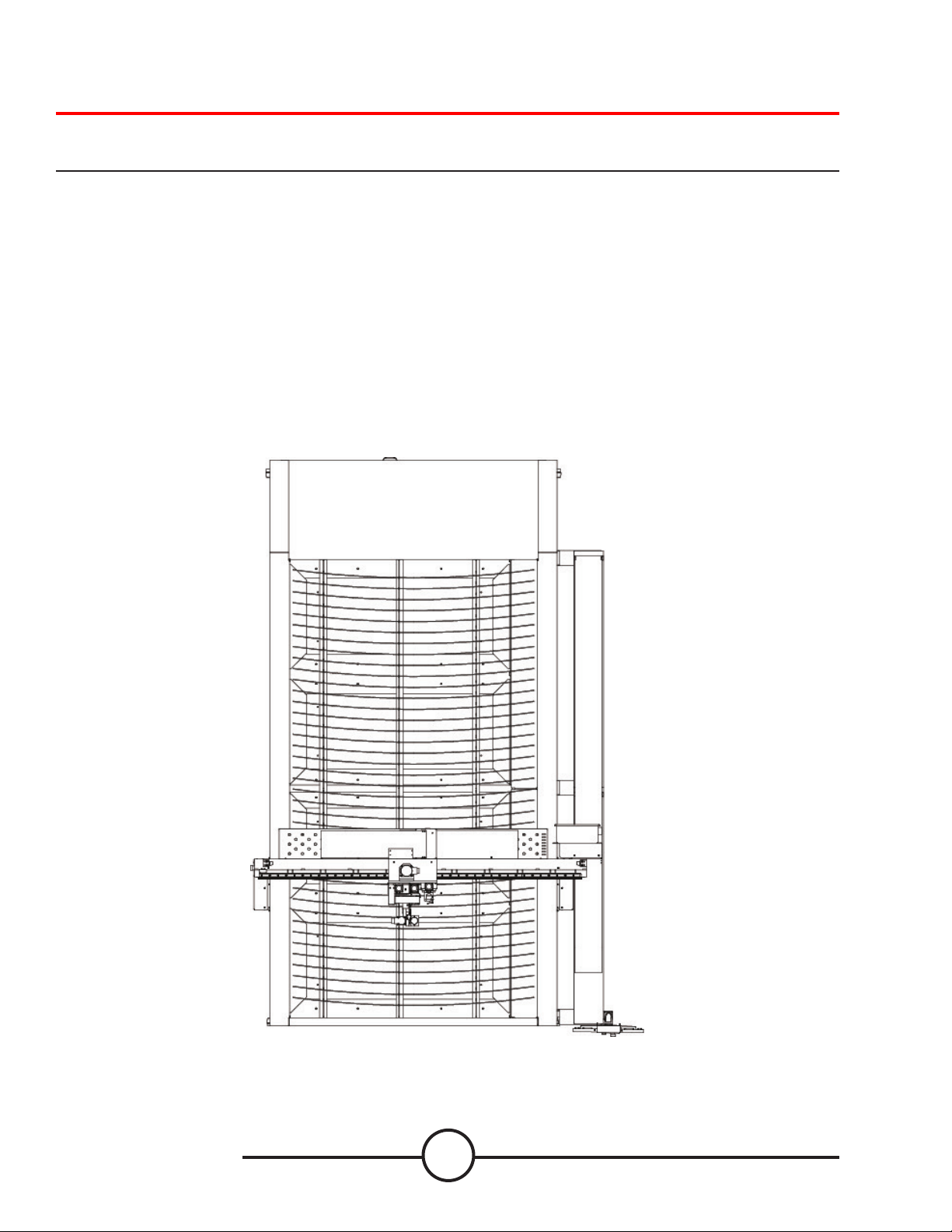
Downdraft Operation
The 5100 in Downdraft conguration, there are 4 zones that are controlled by the program. The “zone” that is active
(open) is dependent on where the job is located in the cutting bed when PROGRAM ZERO is established.
Each zone is controlled by pneumatic actuators to
open/close the dampers inside the table to allow for
OUTPUT
proper air ow. The zones will open/close based on
where the parts are established on the cutting bed
and SET PROGRAM ZERO.
ZONE 4
ZONE 3
ZONE 2
ZONE 1
If a part or nest covers more than one zone, then
multiple zones will open to allow proper ventilation
Output diameter connector ring is 14” diameter.
Output air ow required Fume Extraction (Optional
Accessory)
• 61,801 ft3/hr or 1,750 m3/hr minimum
• Automatic Filter Cleaning, Pressure Controlled.
ZONE 1 ZONE 2 ZONE 3 ZONE 4
Torchmate 5100
OUTPUT
16
Page 30

17
User Guide
Page 31

FlexCut 125 Plasma Controls and Settings
Please refer to the complete operation and user manual for your FlexCut 125 located with the plasma unit. When the
machine is turned on, an auto-test executes; during this test the Control Panel light up.
Controls »
FRONT
1. LCD DISPLAY
2. PRIMARY AIR, GAS PRESSURE GAUGE
AND REGULATOR KNOB
3. HOME BUTTON
4. ONOFF SWITCH
5. TORCH CONNECTION
6. WORK LEAD CONNECTION
7. MENU CONTROL KNOBBUTTON
8. PURGE
BACK
9. AIR OR GAS INLET 14”IN. NPT QUICK
CONNECT
10. RECONNECT PANEL ACCESS
11. INPUT CORD STRAIN RELIEF
12. 14PIN CNC INTERFACE
13. FAN
1
2
3
4
5
6
9
10
7
8
11
Torchmate 5100
12
13
18
Page 32

FlexCut 125 Plasma Cutter Consumable Use
Please refer to the FlexCut operators manual for a complete installation and operation guidelines. Do not over tighten
the consumables. Only tighten until the parts are seated properly.
Product
Name
FlexCut 125 K4811-1 380/400/415/460
Product
Number
Input Power
Voltage/Phase/Hertz
/575/3/50/60
Rated Output:
Current/
Voltage/Duty Cycle
125A/175V/100% 3PH/100%
Input Current @
Rated Output
40/40//40/33/28
Output
Range
3PH
20-125A
Gas Pressure
Required
90-120 PSI
(6.21-8.27 Bar)
MECHANIZED CUT CAPACITY MATERIAL THICKNESS MILD STEEL
Recommended cut capacity at 32ipm 1 in. (25.4 mm)
PIERCE CAPACITY MATERIAL THICKNESS MILD STEEL
Pierce capacity with programmable torch height control
3/4 in. (19 mm)
MAXIMUM CUT SPEEDS MILD STEEL
1/4 in. (6.35 mm) 180 ipm
1/2 in. (12.7 mm) 72 ipm
3/4 in. (19 mm) 40 ipm
1 in. (25.4 mm) 23 ipm
CONSUMABLES STARTER KIT FOR LC125M MACHINE TORCH K43022
Electrode (LC125M) BK14300-1 2 Qty
Shield Cap 45 A - 65 A (LC125M) BK14300-3 1 Qty
Shield Cap 85 A - 125 A (LC125M) BK14300-4 1 Qty
Nozzle 45A (LC125M) BK14300-7 1 Qty
Nozzle 65A (LC125M) BK14300-8 1 Qty
Nozzle 85A (LC125M) BK14300-9 1 Qty
Nozzle 105A (LC125M) BK14300-10 2 Qty
Nozzle 125A (LC125M) BK14300-11 2 Qty
Swirl Ring 45 A - 125 A (LC125M) BK14300-13 1 Qty
Retaining Cap-CTP (LC125M) BK14300-15 1 Qty
Gas Flow
Rate
550 SCFH @90 PSI
260 SLPM @6.21 Bar
H x W x D
in (mm)
20.72 x 12.25 x 25.53
(526 x 311 x 648)
Net Wt.
lb (kg)
118 (53.5)
19
User Guide
Page 33

FlexCut 200 Plasma Controls and Settings
Please refer to the complete operation and user manual for your FlexCut 200 located with the plasma unit. When the
machine is turned on, and auto-test is executed; during this test the screen will change.
Controls »
FRONT
1. LCD DISPLAY
2. HOME BUTTON
3. MENU CONTROL KNOBBUTTON
4. ONOFF SWITCH
5. SHIELD GAS OUTLET
6. NOZZLE LEAD CONNECTION
7. WORK LEAD CONNECTION
8. ELECTRODE LEAD CONNECTION
9. ARCLINK CONNECTOR 5PIN
10. PLASMA GAS OUTLET
11. PURGE
12. SHIELD GAS REGULATOR
13. PLASMA GAS REGULATOR
BACK
14. AIR OR GAS INLET 14”IN. NPT QUICK
CONNECT
1
2
3
4
5
6
14
15
13
12
11
10
9
7
8
20
15. 115V15A AUXILIARY POWER RECEPTACLE
16. 15 AMP CIRCUIT BREAKER
1 7. ETHERNET CONNECTOR
18. 10 AMP CIRCUIT BREAKER
19. FLEXCOOL CONNECTOR
20. INPUT CORD STRAIN RELIEF
21. CNC INTERFACE CONNECTOR
22. FAN
Torchmate 5100
16
17
18
19
21
22
20
Page 34

FlexCut 200 Plasma Cutter Consumable Use
Please refer to the FlexCut operators manual for a complete installation and operation guidelines. Do not over tighten
the consumables. Only tighten until the parts are seated properly.
Product
Name
FlexCut 200 K4812-1 380/400/415/460
Product
Number
Input Power
Voltage/Phase/Hertz
/575/3/50/60
Rated Output:
Current/
Voltage/Duty Cycle
200A/300V/100% 3PH/100%
Input Current @
Rated Output
71/63/55
Output
Range
3PH
20-200A
Gas Pressure
Required
90-120 PSI
(6.21-8.27 Bar)
MECHANIZED CUT CAPACITY MATERIAL THICKNESS MILD STEEL
Recommended cut capacity at 32ipm 1 in. (25.4 mm)
PIERCE CAPACITY MATERIAL THICKNESS MILD STEEL
Pierce capacity with programmable torch height control
3/4 in. (19 mm)
MAXIMUM CUT SPEEDS MILD STEEL
1/4 in. (6.35 mm) 180 ipm
1/2 in. (12.7 mm) 72 ipm
3/4 in. (19 mm) 40 ipm
1 in. (25.4 mm) 23 ipm
CONSUMABLES STARTER KIT FOR LC125M MACHINE TORCH BK244100SK
Removal Tool, Nozzle BK277056 1 Qty
Removal Tool, Swirl Ring BK260105 1 Qty
O-Ring Lubricant BK716012 1 Qty
Internal Retaining Cap 50 A BK244453 1 Qty
Internal Retaining Cap 100 A BK244452 1 Qty
Internal Retaining Cap 150-200 A BK244466 1 Qty
Outer Retaining Cap 50-200 A BK244454 1 Qty
Shield Cap 50 A BK244450 1 Qty
Shield Cap 100 A BK244417 1 Qty
Shield Cap 150 A BK244474 1 Qty
Shield Cap 200 A BK244463 1 Qty
Electrode 50 A BK244431 1 Qty
Electrode 100 A BK244492 1 Qty
Electrode 150 A BK244491 1 Qty
Electrode 200 A BK244470 1 Qty
Swirl Ring 50 A BK244442 1 Qty
Swirl Ring 100 A BK244439 1 Qty
Swirl Ring 150 A BK244443 1 Qty
Swirl Ring 200 A BK244458 1 Qty
Nozzle 50 A BK244425 1 Qty
Nozzle 100 A BK244493 1 Qty
Nozzle 150 A BK244489 1 Qty
Nozzle 200 A BK244469 1 Qty
Gas Flow
Rate
550 SCFH @90 PSI
260 SLPM @6.21 Bar
H x W x D
in (mm)
23.66. x 15.97 x 32.19
(601 x 406 x 818)
Net Wt.
lb (kg)
190 (86.2)
21
User Guide
Page 35

Performing Your First Test Cut (straight torch NON BEVEL)
The LINE SPEED TEST.gm and 5100 Test Cut.gm is provided to determine the proper feed rate in IPMs to cut the
material thickness to the amperage you have set on the plasma power supply. These have been included in your
pre-loaded rst cut on the Torchmate 5100 models. The plasma torch body is pre-loaded with 65 amp consumables
(FlexCut 125) or 100 amp (FlexCut 200) for a 3/16” material cut from the factory. We highly suggest your rst cut is our
pre-loaded, *FC125/200 INLINE TEST CUT 65A/100A.gm to ensure your machine has transported in the same condition it
has left the factory. Please locate the factory test sample located in the waterbed and load a piece of 3/16” mild steel for
the comparison cut test.
1. Press SELECT JOB.
2. Locate FC125/200/400 (amperage of plasma) INLINE TEST CUT 65A/100A (plasma
machine).gm and press OK
3. Verify that your amperage on your plasma power supply is set to 65 amp (FC125) or
100 amp (FC200).
3. 5100 Inline test cut will now show in the display.
4. For the FC125, set the CUT PARAMETERS:
PIERCE HEIGHT to 0.16
CUT HEIGHT to 0.12
PIERCE DELAY to .5
For the FC200, set the CUT PARAMETERS:
PIERCE HEIGHT to .20
CUT HEIGHT to .11
PIERCE DELAY to .3
5. Set MODE to AUTO and SAMPLE VOLTAGE to ON.
IHS (ohmic detection) set to ON and IHS MODE to ALWAYS.
Complete AVHC settings for various material can be found in the plasma power
supply cut charts.
AVHC settings will change for dierent amperage and material thickness being cut.
See your FlexCut manual for further instruction after performing your rst cut.
6. Jog the head over to the Lower Left corner of the material you are going to cut and
press SET PROGRAM ZERO.
7. Assure that the FEED RATE OVERRIDE is set to 100%
8 PRESS RUN JOB (machine may throw sparks)
9. The cut will progress as follows.
Rapid travel to the rst inside feature.
Z Axis moves toward the material, touching the top of the material.
(IHS -ohmic detection)
Torch retracts to set PIERCE HEIGHT and will re.
Dwells until the PIERCE DELAY is expired.
Drops to set CUT HEIGHT and starts the program.
Will cut all inside features rst, then move to the outside geometry.
Torchmate 5100
Once cut is complete, compare the cut to the provided sample and verify that they
match. This will provide proof that the machine is functioning properly.
If you need to stop the
machine at any time
please hit the stop button
on the touch screen.
22
Page 36

Performing Your First Test Cut (BEVEL)
With the BEVEL head, the plasma torch body is pre-loaded with 125 amp consumables (FlexCut 125) or 150 amp (FlexCut
200) for a 1/2” MS material cut from the factory. We highly suggest your rst cut is our pre-loaded, *FC125/200 BEVEL
TEST CUT 105A/150A.gm to ensure your machine has transported in the same condition it has left the factory. Please
locate the factory test sample located in the waterbed and load a piece of 1/2” mild steel for the comparison cut test.
1. Press SELECT JOB.
2. Locate FC125/200/400 (amperage of plasma) BEVEL TEST CUT 105A/150A (plasma
machine).gm and press OK
3. Verify that your amperage on your plasma power supply is set to 105 amp (FC125) or
150 amp (FC200/SPII).
3. 5100 BEVEL test cut will now show in the display.
4. The CUT PARAMETERS along with the AVHC settings are pre-coded in the g-cod eof
the les. To have the system “see” these parameters, TOGGLE the CUT CHARTS to
CHARTS. This will tell the controller to look at the code to pre-populate the settings.
AVHC settings will change for dierent amperage and material thickness being cut.
See your FlexCut manual for further instruction after performing your rst cut.
5. Jog the head over to the Lower Left corner of the material you are going to cut and
press SET PROGRAM ZERO.
6. Assure that the FEED RATE OVERRIDE is set to 100%
7 PRESS RUN JOB (machine may throw sparks)
8 . The cut will progress as follows.
Rapid travel to the rst inside feature.
Z Axis moves toward the material, touching the top of the material.
(IHS -ohmic detection)
Torch retracts to set PIERCE HEIGHT and will re.
Dwells until the PIERCE DELAY is expired.
Drops to set CUT HEIGHT and starts the program.
The Torchbody will laydown inside the loops to accommodate the bevels in
the design.
Will cut all inside features rst, then move to the outside geometry.
60° ±4°
3.000 ±.0 32
1.000
30.0°
UNDERCUT, NOMINAL BEVEL TYPE
Once cut is complete, compare the cut to the provided sample and verify that they
match. This will provide proof that the machine is functioning properly.
If you need to stop the
machine at any time
please hit the stop button
5.000
.500
on the touch screen.
23
User Guide
Page 37

Overview of the Visual Machine Designer
Visual Machine Designer (VMD) is the driver software to all ACCUMOVE® CNC controllers. The majority of the control of
the table can be found on the main screen while hosting features that can create and manipulate les. This quick guide
will give you an overview of the features along with it’s operation.
Main Screen:
2
1
7
3 4 5 6
The main screen of the VMD is broken into sections for easy navigation and operation. Overview of all the buttons and
functions will be covered in sections.
1. Job group - Opens and controls all apects of the le being entered or creation of jobs
2. View Screen - Shows the graphic of the job, g-code of the job, or a graphic of the lifter station movements.
3. Datum/Program Zero - Establishes the machine zero through DATUM along with the program zero on the
machine.
4. Cut Parameters/AVHC - Settings for the height control and it’s functions.
5. Run group - These buttons control the start and stop of the job.
6. Jogging - Controls the torch movement on the machine along with program run speed
7. Dashboard - Displays the coordinates of the head along with all of the indicators being monitored on the
machine.
Torchmate 5100
24
Page 38

Job Group:
The JOB GROUP at the top, covers any “job” type functions. This group directly deals with selecting a job, creating a job
(Shape Library), or Alter job functions.
Select Job:
This is how to open jobs into the VMD.
In the SELECT JOB area shows the “HOT FOLDER” and the loaded jobs
in that folder. * C:\ControllerData\Jobs is the HOT FOLDER.
To select another source, then press BROWSE and that will open the
standard WINDOWS dialog.
In the PREVIEW window will display the selected job from the list.
Nesting:
This opens the VMD NESTING.
See the NESTING section to get an overview of the features.
Shape Library:
This allows you to create a user dened shape based on 27 of
the most common parts.
See the USING THE SHAPE LIBRARY section for details.
Job Setup:
JOB SETUP allows you to make alterations to the job itself.
ROW AND COLUMN: Allows you to add mulitples by adding
numbers to generate a GRID ARRAY of the job you have
selected.
TRANSFORMS: Allows you to MIRROR, ROTATE, or SCALE
your job.
MATERIAL SENSING: This works in conjuction with the CUT
PARAMETERS by setting a measurement for the TOP OF
MATERIAL and the MATERIAL THICKNESS of the plate you
are cutting.
25
User Guide
Page 39

Job Group: (cont)
Tool Library:
In TOOL LIBRARY congures and controls the tool outputs
on the machine.
KERF and DWELL times can be added along with
programming the oset to the plate marker acessory.
Log On:
LOG ON switches users of the VMD software.
OPERATOR is the standard user.
ADMIN opens the MACHINE SETTINGS. (password protected)
TECH SUPPORT is used only for Tech Support. (password
protected)
Shutdown:
SHUTDOWN will close the VMD and power down the
computer.
This should be used when shutting down the system.
Torchmate 5100
26
Page 40

View Screen:
The VIEW SCREEN in the VMD uses colors and will display the machine limits, head location, and job location. There are
four tabs along the top that will show a visual of the job, g-code of the job, or a graph of the lifter station. If you have a
FlexCut 200 attached to the machine, you can directly control the FlexCut 200 by using the Plasma Contol tab.
Plan View:
This displays the MACHINE LIMITS in blue. The head is represented with white crossed lines. Plasma assigned tool paths
are display in red. Plate Marker assigned tool paths are displayed in Magenta. Rapid travels will be a dashed grey line.
Zoom to Machine will zoom to the programmed machine
limits.
Zoom to Job will zoom to the job loaded.
Run From Torch position will start the job where the torch is
located on the job.
Maximize Viewport will display all views in one screen.
Job Program View:
This displays the g-code of the job that is loaded.
Edit Job will open the current g-code in a text editor.
Height Control View:
This displays in a moving graph the lifter station movements
while operating.
Trace Pause/Resume will pause the graph if tracing.
Trace o/on will toggle showing the lifter station being
monitored.
27
User Guide
Page 41

View Screen: (cont)
Plasma Console: (FlexCut 200/SPII)
The Plasma Console controls the settings of the plasma from
the HMI. This allows the operator to directly control the
plasma power supply without having to navigate away from
the HMI.
The settings that can be changed are:
• Current
• Plasma Process Mode (Cut, Plasma Mark, Expanded,
Gouge)
• Purge
• VMD in Control: Determines the HMI, or Plasma,
controlling the plasma settings.
Torchmate 5100
28
Page 42

Datum / Program Zero Group:
This group controls the startup of the machine along with setting jobs to start from a certain location on the table.
DATUM:
Datum has several features. When rst starting up your machine,
datum will power your motors and move the machine to establish
it’s MACHINE ZERO.
Once the torch has moved to the back left corner, the machine is
ready to operate.
Set Program Zero:
SET PROGRAM ZERO establishes the x0:y0 where the torch body is
positioned on the table. This is the origin where the job will start
from.
When running a job, you will move the torch body to the front left
corner of the material you are cutting. By pressing SET PROGRAM
ZERO, will establish the job’s absolute zero position.
Go To Program Zero:
Pressing this will move the torch body back to the established
PROGRAM ZERO
29
User Guide
Page 43

CUT PARAMETERS and AVHC:
Once you have your job ready to run, getting the settings correct and understanding their function is crucial to getting
quality cuts on your table. This covers go over the Cut Parameters and the AVHC settings.
Cut Parameters:
All the parameters in the Cut Parameters and AVHC tab set
the torch in proper position in relation to the material during
operation. Most of the parameters can be found in your FlexCut manual under CUT CHARTS.
• Transfer Height is the distance the Z-Axis will travel
down to transfer the PILOT ARC prior to Pierce height.
(used on Spirit II HD only) Enter 0 for conventional
plasma
• Pierce Height is the distance the head sits above the
material during piercing.
• Cut Height is the distance between the torch tip and top
of material during cutting.
• Pierce Delay is the time delay for the torch to pierce
through the material before executing movement.
• Retract Height is the distance the head will move up
during rapid travels when running a job.
• Arc Voltage is the voltage feedback comparison value. If
using SAMPLE VOLTAGE this will adjust during cutting.
AVHC (Automatic Voltage Height Control):
MODE is a toggle between MANUAL or AUTO.
• Manual - The torch will stay at the Cut Height
established at each material pierce. The torch will
not automatically adjust to the cut height during
cutting.
• Auto - The torch will maintain the distance entered
in CUT HEIGHT and prole the material based on
the SET VOLTAGE and the CURRENT VOLTAGE being
read from the plasma power supply.
Torchmate 5100
30
Page 44

CUT PARAMETERS and AVHC:(cont)
AVHC (Automatic Voltage Height Control):
Sample Voltage is a toggle On or OFF.
• On (with MODE: AUTO): At the beginning of the cut the
controller learns the proper Arc Voltage and maintains the
desired Cut Height value entered in CUT PARAMETERS.
• O (with MODE: AUTO): The AVHC will adjust based on
the SET VOLTAGE and CURRENT VOLTAGE only. If the SET
VOLTAGE is dierent than the CURRENT VOLTAGE then the
lifter will adjust to account for the dierence.
• On/O (with MODE: MANUAL): This feature is disabled.
IHS (Initial Height Sense) this setting turns OHMIC DETECTION on or o.
• ON: The head will detect material when the ohmic cap comes
into contact with the grounded, conductive material on the
table. Once detected the head will retract to PIERCE HEIGHT
setting.
• OFF: The head will move to TOP OF MATERIAL setting (Job
Setup) and retract to PIERCE HEIGHT.
IHS MODE is the process used to detect the material height and how it
reacts between pierces.
• Optimal: First pierce the head will detect the material via
OHMIC and will not detect the material for a set distance
away from the rst OHMIC detection.
• Always: The head will detect material via OHMIC at every
pierce.
CUT CHARTS this setting will allow the user to dene the cut parameters or have them prepopulate via g-code generated throught the
nesting process.
• Charts: Uses the predened cut settings generated through
the NESTING process and populates the settings in the CUT
PARAMETERS
• Custom: The operator enters the values into CUT
PARAMETERS from the cut charts.
RESET Z POSITION resets the Z lifter to its Zero Position by moving the
head to its upper stroke and re-establishing its zero position.
31
User Guide
Page 45

Oxy and Water Controls:
The VMD can control OXY cutting torches with the OXY tab. This allows to SET and CAPTURE time delays. The WATER
LEVEL tab, controls the water level in the table along with a LOW WATER indicator.
OXY:
LIFTER controls the lifter stations UP/DOWN position.
• Up will raise the lifter.
• Down wil lower the lifter.
PRE-HEAT sets and alters the PRE-HEAT time required for
the OXY cutting.
• OFF is a TOGGLE to ON or OFF. This will activate
the PREHEAT DELAY time that is entered in the
PREHEAT DELAY dialog.
• EXTEND is a toggle between EXTEND and
CAPTURE. When EXTEND is PRESSED, will extend
the time until released. It will then CAPTURE the
time
• CONTINUE is active or not. When pressed, will
turn on the HIGH PRESSURE REGULATOR to start
cutting.
WATER LEVEL:
WATER LEVEL allows the operator to control the level of
water in the water table. A LOW WATER indicator to show
when water needs to be added to the table. To properly ll
the table with water, follow the water ll instructions on
pg. 43
• RAISE WATER. When held down, will raise the
water. Release the button to stop raising the water.
• LOWER WATER. When held down, will drop the
water. Release the button to stop at the level
required.
• If the LOW WATER indicator is displayed, the water
level in the tank is low and will not allow to raise
the water past that level until the water level is
satised.
Torchmate 5100
NOTE: Hydrogen gas may be formed and be trapped under aluminum work pieces
when they are cut using a water table.
DO NOT cut aluminum alloys underwater or on a water table unless the hydrogen gas
can be eliminated or dissipated. Trapped hydrogen gas that is ignited will cause an
explosion.
32
Page 46

RUN Group and Jogging:
This group controls the start and stop of a job plus allows you to alter states of the plasma. Jogging allows the user to
move the head by pressing on the direction. Also, the jog is tabbed so being about to move the head to the proper location
anywhere on the table.
Active Run/Dry Run:
This button is a TOGGLE between ACTIVE RUN and DRY RUN.
ACTIVE RUN: This will activate your torch to re when you
RUN a job.
DRY RUN: This deactivates your torch from operation. If in
DRY RUN, the torch will simulate all movements without
ring the torch.
Laser:
This will activate the Laser pointer accessory.
RUN JOB:
RUN JOB will start the job that is loaded into the VMD.
STOP:
STOP button will stop the machine during any movement or
process.
RESET:
This will reset the job to start over. If the job has started and
not completed you will need to RESET to start the job over.
Jog:
The JOG keys are laid out in the manner as the table moves.
By pressing more towards the center of the jog key will move
the torch body slower and then on the outside it will move
faster. The JOG window is comprised of three seperate tabs:
Continuous, Incremental and Point.
On the bottom, is the FEED RATE OVERRIDE %. This will alter
the running feedrate of the job that is active. This is used
to ‘feather’ the feedrate while running to get the best cut
quality.
33
User Guide
Page 47

Jog: (cont)
Continuous Jog:
By pressing a direction will move the torchbody in the direction you are pressing. When released the head will stop.
Incremental Jog:
By pressing a directional arrow, it will move the torch body
in the direction you are pressing, while using the Increment
Distance slider bar to move it that distance.
Using the INCREMENT DISTANCE slider will give you increments between .000 - .100. or enter any distance into the
dialog to get exact measured movement.
Torchmate 5100
34
Page 48

Jog and Dashboard:
Point Jog:
Point Jog allows the user to dene where they want the head
to travel to and from what source location.
Select where you want the torch to start, what feed rate to
travel and the X / Y coordinates and press MOVE TO POSITION.
CUT TO POSITION works the same way except it will go
through the IHS sequence and re the torch. This works to
help cut remnants and straight lines.
Dashboard:
DASHBOARD displays job name and table coordinates along
with other details about the machine.
• Job Name: Display the active job loaded in the VMD
• Machine Position: This shows the torch coordinates
to the MACHINE space
• Position Relative to Job Origin: These coordinates
display based o of the SET PROGRAM ZERO
• Green Indicators: The green indicators show when
the signal is turning on/o the assicated tool.
• AVHC Active: Displays when the AVHC is adjusting.
• Voltage: Displays the SET VOLTAGE the machine is
tracking along with the current RAW ARC VOLTAGE
feedback from the plasma during cutting.
• Plasma Pierce Count: This is for keeping track of
how many pierces the plasma consumables. You will
RESET when you change the consumables.
• Material Thickness: Enter the material thickness of
the plate you are cutting.
• TOOL: Indicates which tool is active. 1 is plasma, 2 is
platemarker
• Feedrate: This displays the actual feedrate the
machine is moving at.
• Timer: This is the elapsed time from pressing RUN
JOB to when the job is completed.
35
User Guide
Page 49

Dashboard: (cont)
Dashboard:
DASHBOARD Indicators:
• OK TO MOVE: Indicates when the plasma has pierced
through the material and is ready to start the
program.
• IHS: Indicates when the material is detected via
OHMIC.
• Breakaway: Indicates if the breakaway circuit is
open/closed
Extended:
EXTENDED tab displays details about the job and it’s ACTIVE
CUTTING perimeters. Times are in seconds and lengths are in
in/mm.
• X Y Z: Display the overall dimentions (in/mm) of the
job being cut.
• FEED: This shows the speed of the torch body.
• Plasma ON/OFF: Displays the amount of ON/OFF
commands as the code is read. Can be used as a
pierce counter.
• Acceleration Time: Displays the time the machines is
accelerating during the cut.
• Constant Velocity Time: Displays time spent during
rapid travels inbetween features.
• Deceleration: The time spent in deleceration.
• Torch On/O Time: Displays the total time of the
torch being active/inactive.
• Cycle Time: Timer showing TOTAL active program
time. Timer will pause when the machine is paused.
• Cut Length: Shows the total length of the cut.
• Slew Length: Length of non-cutting, rapid
commands.
• Output ON/OFF Mask:
• Tool Mask: Total tools used in job.
Torchmate 5100
36
Page 50

Using the Shape Library in VMD
In the VMD, you can generate one of 35 standard shapes without needing to generate them in your CAD software.
Access the Shape Library:
To get to the Shape Library, press SHAPE LIBRARY on the top
center of the VMD screen. The Shape Library oers the most
popular 35 shapes to customize to your dimensions along with
Lead in/Out, Feed Rates, and Tools. Select the shape you are
looking for and press OK. This will open the shape conguration
for the shape selected.
Congure your shape:
First, select the TOOL you are planning to use: Plasma, Plate
Marker, or Oxy. Then enter a value for the Feed Rate. Recommend
using 100 for the feed rate and controlling the output feed rate
with the FEEDRATE OVERRIDE PERCENTAGE slider bar
Lead in radius will create a radius for your lead -in. If a line leadin is required, then enter 0.
Lead In is the length of the pierce point movement into the tool
path. This is usually .12.
Lead out is the length of the cut created out of the cut path. If
using plasma, enter 0
Overburn is the measured length past the end/start point. Used
for thicker materials or in the oxy process.
Once all of the parameters are entered, press OK.
37
User Guide
Page 51

Using the Shape Library in VMD (cont)
Save your Shape:
Once you press OK, you will be prompted to SAVE your shape.
Double click the JOBS folder. By default, the name of the le will
be the shape you selected or can be changed to a user dened
naming convention. Once named press SAVE.
Open shape in VMD:
In the MAIN screen, press SELECT JOB. This will open the Select
a Job screen. Select the job from the list. If you didn't save in
the JOBS folder you will need to press BROWSE and locate your
job. Once selected, press OK. The job will display in the RUN
screen.
Torchmate 5100
38
Page 52

Running a Job
When you have a GM format le to run or shape generated in the VMD ready to cut there is a simple process to follow to
get the job produced through the VMD.
Datum:
When you rst start the Visual Machine Designer and are connected to the Accumove
controller the machine needs it's conguration loaded and motors powered on. A
screen displays PLEASE SWITCH DRIVES ON. Press HIDE and then in the lower left
corner press DATUM. The Torch will travel to the limits of the machine and establish
the MACHINE ZERO.
Open a Job:
Once the MACHINE ZERO has been established it is time to open a job and get it prepared to cut. Press SELECT JOB and locate your le.
Establish Program Zero:
With the job loaded, you will need to determine the start point of the job. Using the
JOG keys, move the head to the front left point (-X, -Y) of the material where you want
to start your cut. Once there, press SET PROGRAM ZERO. Your job that is loaded will
move to that point in the RUN screen. Press ZOOM TO JOB to view your part. The
PROGRAM ZERO can be established anywhere within the machine limits as long as the
job will t. The PROGRAM ZERO point established is where the job will run from. The
G-CODE will run in positive directions (+Y,+X) from the ZERO point.
Verify that the job will t on the material along with enough margin that the torch will
not run o of the material.
39
User Guide
Page 53

Running a Job (cont)
Cut Parameters and AVHC Settings:
The nal step is entering the cut chart settings into the Cut Parameters and AVHC
panels based on the material thickness and amperage on the plasma.
For this example, will be entering the settings for 3/16” material using a FlexCut 200
plasma power supply set at 100 amps with 100 amp consumable stack.
FlexCut 200 100 amp CUT CHART provided:
Settings that need to be entered in your Cut Parameters panel are as follows:
• PIERCE HEIGHT: .20
• CUT HEIGHT: .11
• PIERCE DELAY: .3
Other settings in the AHVC panel that will be changed.
• MODE: AUTO
• SAMPLE VOLTAGE: ON
• IHS: ALWAYS
• OHMIC SENSING: ON
• CUT CHARTS: CUSTOM
Set Feed Rate:
In the Cut chart is the OPTIMUM FEED RATE. Pending on how the job was created the
feed rate will need to be established in the job. If the feed rate was set to the OPTIMUM
FEED RATE, then make sure the FEED RATE OVERRIDE is set to 100%.
You can alter the feedrate by percentage by adjusting the sliderbar.
Run the job:
With all the settings entered into the CUT PARAMETERS/AVHC boxes and the feed rate
set in the FEED RATE OVERRIDE % time to run the job. To verify the machine will run
with the settings change the ACTIVE RUN to DRY RUN to "simulate" the job. Dry Run
will perform all machine sequences and movements without ring the plasma. Once
the Dry Run is complete, the job will automatically reset.
Torchmate 5100
If satised with the Dry Run and the machine movements, toggle DRY RUN to ACTIVE
RUN to cut the job loaded.
Press RUN JOB
40
Page 54

Cut Quality:
The total goal is to make sure the cuts coming o of your table are the best possible.
This means that there is minimal dross accumulation on the underside of your cut
parts and minimal bevel on the sides.
We have provided a le to cut to verify the feed rate for the material you are planning
to cut with the amperage set on the power supply. The LINE SPEED TEST is in the job
list and should be run on every thickness of material at the specied amperages in the
cut chart to give you a visual reference to the output. The test cut is a 3" x 4" coupon
that consists of 9 lines. Each line is programmed to run at dierent speeds to illustrate
the eects that speed has on cut quality.
With the FEED RATE OVERRIDE % at 100, the rst line cuts at 170 ipm and drops 10 ipm
each line until the last line set at 80 ipm and the outside perimeter is 100 ipm. If the
FEED RATE OVERRIDE % set to 50, the lines would range from 85 to 40 with the outside at 50. In the cut chart, verify the amperage and thickness of material. Change the
PROGRAM FEEDRATE OVERRIDE % if you need the feed rates higher or lower according to the thickness of material and amperage you are running.
• Load the LINE SPEED TEST.gm le
• Enter in the AVHC settings according to the cut chart.
• Jog the head to the bottom left corner. SET PROGRAM ZERO
• Run the LINE SPEED TEST.
Once the test is complete, there are a few things to look for; on the top of the cut, you
want to see a clean cut without a lot of bevel. The ideal cut has the same kerf width
both on top through to the bottom.
Line Speed Test:
On the backside, you will observe the width (kerf) of the cut and the dross accumulation. The key is the 3-4 lines that have the least amount of dross. Picking at the dross
with a tool, the dross should be easy to remove from the test cut. The optimum speed
is the high end of the three lines that are clean without much dross accumulation.
Straight lines will cut clean, but the “inside features” of your cuts will be at a lower
speed because of the nature of movement and mechanics of the machine. With those
three, you know that the inside features will be just as clean as the straight line.
Front Back
80 ipm
90 ipm
100 ipm
110 ipm
120 ipm
130 ipm
140 ipm
150 ipm
160 ipm
170 ipm
Tar get
Too Fast
In this example: the 110 - 90 ipm will be the best speed for this material thickness and
amperage setting. This process will be used for every thickness of the material you plan
on cutting to establish the proper speed. Once established, these coupons can be used
as a visual cut chart. Use the provided sheet to document your settings.
Line Speed Test cut:
41
User Guide
Page 55

Build Your Own Cut Chart
The FlexCut manual includes a factory cut chart. Use this template to create your own custom cut charts using the line
speed test.
Material Thickness
Type
Amperage Voltage Cut Speed Pierce Delay Pierce Height Cut Height
Torchmate 5100
42
Page 56

VMD On-Board Nesting:
The VMDNest is an onboard irregular part nesting CAM software. This allows IMPORTING DXF and DWG les without
needing an osite CAM software to generate the proper G-Code. The NESTING will apply the kerf correction along with
the appropriate lead ins to all features. This will generate the tightest nest available for the size of material entered into
the system.
When you want to import a DXF/DWG into the VMD or if you want to add multiple les
and nest into a predened layout you need to use the NESTING feature. By pressing
NESTING, will display the NESTED JOB LIST screen. To start a new nest, press NESTED
JOBS. Select NEW NESTED JOB and the ADD NESTED JOB dialog opens.
In this dialog, enter a name for your nest in NESTED JOB NAME. This will become the
le name of your project. Each dialog after is a drop down. Find the thickness of material you plan on cutting along with the size of sheet. Select the table/plasma cutter you
are using along with the amperage approriate to the application and press SAVE.
Start New Nest:
43
User Guide
Page 57

Nesting
Add Parts:
ITEM LIST will open along with the NEST LAYOUT. To add parts, go to the right toolbar
and press PARTS. This will open the parts list. Select IMPORT CAD DRAWINGS for DXF/
DWG les. This will bring up the PART SELECTOR.
Apply Tool Paths:
Torchmate 5100
At the top of the screen will be FILE TYPE, SOURCE, and DESTINATION.
File Type: Toggles between DXF and DWG type les.
Source: Location of le source (i.e. Flash Drive, Job Folder)
Destination: Location on where the output les will save. VMD default folder is
located at C:\ControllerData\Jobs
IMPORTING PROPERTIES holds basic changes to the POST and importing of the le.
TOOLING PROPERTIES holds tool pathing conguration for sequencing, kerf correction,
and lead ins. Change these setting if you need particular leadins or kerf diameters.
LAYER MAP seperates the layers present in the job. Select the appropriate process for
the layers to be PLASMA, PLASMA MARKING, IGNORE.
44
Page 58

Nesting
The two checkboxes: VERIFY and ARTWORK.
Verify will display the parts to look at layers and other details on the individual
parts.
Artwork will change the tool-paths to an ONLINE toolpath and bypass the lead
in, kerf adjustments.
VERIFY:
By checking VERIFY, then pressing ADD will open the PART IMPORT PREVIEW.
In this screen allows the user to select and change the properties to the individual parts and its components. If you have LAYERS assigned in your le, then you can
change to a particular tool
Once all adjustments have been made, press EXPORT ALL PARTS and the job will get a
tool path assigned to the part.
The TOOLPATHS will display in the PARTS LIST on the right. Once all of the parts are
toolpathed, press ADD TO JOB.
This will take you back to the ITEM LIST.
45
User Guide
Page 59

Nesting
Add Parts:
Once all of the settings are made in the TOOLING PROPERTIES, press SAVE and it will
maintain those settings for that material and amperage.
The left side of the screen select the parts you want to IMPORT and Press ADD. This
will bring up the ITEM LIST again but with the parts populating the left side. Change
the quanities of your parts by clicking over the QUANTITY and will bring up a dialog to
add numbers to the quantity.
Make Nest:
When all the parts have the proper quantity, go to the right button list and select
NESTING.
Press NEST and will display a pop up asking for ALL or SELECTED parts. Make your
selection and press OK. This will then arrange your parts into the material and display
the layout in the Job screen.
Torchmate 5100
46
Page 60

Nesting
If your nest does not need editing or is just a single part then in the right toolbar select
COMPLETE NEST. This will open the CREATE JOB DIALOG. Enter the location you want
the job to save and verify the amperage you are cutting. Then press OK.
In the NEST screen at the bottom left, press BACK (RUN) button and will return you to
the VMD RUN screen.
Now to run your nest, go to SELECT JOB and locate your le. In the AVHC tab, toggle
AVHC CUT CHARTS to CHARTS. In the le, the optimum values will auto populate the
CUT PARAMETERS for the material thickness and amperage set.
Complete Nest:
Open nest in VMD:
Process and run the le as any normal le.
For more detailed instructions of the VMD and it's complete feature set go to the VMD
manual.
47
User Guide
Page 61

5100 Bevel
A
C
Z
45° 45°
Understanding the capabilities of the bevel head and the cuts that can be programmed is the rst step in getting quality cuts on the 5100. The mechanics of the bevel can support up to 50° of movement in the A and C axis. (limited by
consumables). The bevel allows for a variety of complex cuts that can be produced on the 5100 with material thicker than
3/8” (9.5 mm).
BEVEL AXIS IDENTIFICATION
Bevel Axis:
A: Moves towards/away from lifter station
C: Moves clockwise/counter clockwise on lifter
station
Z: Moves up/down while controlling the height
of the torch.
BEVEL CUTS Available
BEVEL KNIFE EDGE BEVEL KNIFE EDGE WITH LAND BEVEL K-CUT NO LAND
BEVEL K-CUT WITH LAND BEVEL UNDERCUT KNIFE EDGE BEVEL UNDERCUT WITH LAND
Torchmate 5100
48
Page 62

Create a Bevel Cut
To program a bevel cut requires the le to be processed through the QuickCAM Pro software package. This walkthrough
will cover importing a basic shape (DXF), apply two separate bevel cuts, and export the G-CODE for the machine to cut.
DXF Part
To start, have a DXF part from your CAD software generated.
Launch the QuickCAM Bevel software by double clicking the icon.
Once open, a laucher will show all of the options that are available. Select DRAW
The software will open and DRAWING TYPES window will display. Enter in a SHEET
LENGTH and SHEET WIDTH. This measurement will default to 120” x 60”. To toggle
between metric and imperial measurements is available in the drop down.
Press OK
In the upper left corner, select the FOLDER or go to FILE/OPEN.
Once the WINDOWS BROWSE dialog opens, change the FILE OF TYPE to DXF. This will
allow you see only DXF les.
49
User Guide
Page 63

Create a Bevel Cut (cont.)
Select the le you want to create the CUT FILE out of and press OPEN.
In order to get the proper POST and material set up for the cut le, navigate to the
bottom of the layout and select EDIT MACHINE.
Once the MACHINE SELECTION window opens, select the FlexCut 200 (or other power
supply/OXY). Press OK.
Select EDIT MATERIAL. The MATERIAL window will display. Locate the thickness of
material planning to be cut. SELECT it and press OK.
Torchmate 5100
50
Page 64

Create a Bevel Cut (cont.)
The NEST SETTINGS dialog will display which amperage is appropriate for the material that
was selected along with air combination you are using. The AMPERAGE can be changed if
the thickness is within multiple Amperages. CUT GAS can be altered based on the material
and amperage being used. Press SAVE.
The job will now display in the DRAW program.
Left click on SELECT OBJECT in the top tool bar.
Left click on the lines to create the BEVEL on. Each line will show dotted when selected. On
the right side of the screen will display the BEVEL tool path toolbar. Select the bevel type
you wish to apply to the job.
51
User Guide
Page 65

Create a Bevel Cut (cont.)
Once the bevel type is selected, it will bring up the options for that bevel process.
1. Knife Edge
2. Undercut
3. Knife with Land
4. Undercut with Land
5. K-Cut with Land
Each process has dierent
variables that can be entered
for each type cut. Cuts with
LANDs will process two cuts
per bevel to accommodate the
land portion.
1. Knife Edge
3. Knife Edge with Land 4. Undercut with Land
5. K-Cut with Land
2. Undercut
After entering the parameters for the bevel, press OK.
Torchmate 5100
52
Page 66

Create a Bevel Cut (cont.)
The image will display THICKER lines where the bevels have been applied. If multiple bevel
cuts need to be applied, select the lines and assign the bevel type.
To apply the tool path to the job after all the bevels have been entered, press the APPLY
PATH function. This will APPLY the appropriate tool path for your cut. The drawing is blue,
and the tool path will be red. BEVEL cuts will generate a “LOOP” to allow the torch body to
maneuver into the appropriate position for the bevel cut.
53
User Guide
Page 67

Create a Bevel Cut (cont.)
After pressing the APPLY PATHS button, Save your le by going to FILE/SAVE.
When the dialog comes up to SAVE THE NESTED SHEET press YES.
Now go to FILE/EXIT
In the QuickCAM Bevel dialog, select ORDER PROCESSING.
In the ORDER PROCESSING window, press ADD JOB.
The ADD JOB window will appear.
Torchmate 5100
54
Page 68

Create a Bevel Cut (cont.)
Enter a name into JOB NAME: If METRIC is required, check METRIC.
Press SAVE
The EDIT JOB GROUP window will populate. Press SAVE.
To add the part to the NEST, press ADD ITEM.
55
User Guide
Page 69

Create a Bevel Cut (cont.)
The BROWSE window will open. Locate and select the job; the le will have a .DRW extention.
Press OPEN.
The JOB MANAGER will show the loaded job and display the tool path to the job in the lower
left. In the ITEM LIST, changing the QUANTITY will to allow for irregular part nesting based on
the sheet size entered.
Press NEST SETTINGS at the top of the screen.
This will open the NEST properties. In the upper left, verify that the POST is set to your Plasma
power supply. At the bottom of the NEST SETTINGS verify the AMPS and AIR.
Torchmate 5100
56
Page 70

Create a Bevel Cut (cont.)
In the CENTER, enter the size of material you have for the NEST.
Enter 1 in the # OF SHEETS
Press NEST SETTINGS at the top of the screen.
This will open the NEST properties. In the upper right, verify that the POST is set to your
Plasma power supply. At the bottom of the NEST SETTINGS, verify the AMPS and AIR for
the POST to write the CUT SETTINGS for your part.
Press NEST.
JOB MANAGER will open and display your nest along with the part in the display.
Press POST PROCESS
57
User Guide
Page 71

Create a Bevel Cut (cont.)
After pressing POST PROCESS, the POST SETTINGS dialog will open.
This will state the POST to use in a drop-down dialog. Verify that the plasma power supply
is correct.
The default PATH is C:\DOWNLOADS
To save to the HOT FOLDER in VMD, change the PATH to C:\CONTROLLER DATA\JOBS
To save to a Flash Drive, or another drive, press the three dots and open the BROWSE
dialog.
Your FILE will be named numberically based on the NESTED PLATES SHEET NAME.
In this example, the CUT le would be named 000020001.GM
In the TOP tool bar area, press CLOSE JOB.
The NESTED JOB MANAGER will display. Press the X in the upper right to exit out of the
software.
The le can then be brought into VMD for cutting.
Torchmate 5100
58
Page 72

Red Dot Indicator Accessory:
The Red Dot Indicator on the 5100 allows the operator to get exact placement of the torch body on the table by emitting a
laser “DOT” onto the plate. The DOT will show where the torch body is at in relation to to the plate. This works for setting
the PROGRAM ZERO or using the PLATE ALIGNMENT feature. The Red Dot will only be active during DRY RUN and will
automatically shut o when RUN JOB is pressed.
Operation:
To operate the laser nder, toggle the ACTIVE RUN to DRY RUN.
In the DASHBOARD, enter the thickness of material you are cutting, in the MATERIAL
THICKNESS dialog. This will make the Z-Axis move to a preset position based on the
material thickness when the LASER is active.
Once the MATERIAL THICKNESS is entered, press on the LASER button. The head will
lower towards the plate to its set measurement and turn the laser is on. You will see a
red dot on the material.
To start a job, toggle the DRY RUN to ACTIVE RUN. The laser dot will turn o when
RUN JOB is pressed.
59
User Guide
Page 73

Basic Maintenance:
The 5100 requires basic maintenance to keep the machine working and moving properly. The operator will be responsible
for several tasks as outlined in this basic guide.
• Regular cleaning ensures that the table runs as precisely as possible. A build up of dust can put stress on parts and
cause excessive wear or lead to cutting problems.
• Recommend to wipe down any exposed, un-coated metal and spray with a dry silicone lubricant and wipe o the
excess. This process will help eliminate any corrosion build up on the exposed metal.
Machine:
Since the gantry rides on linear rails, you will need to grease the cassettes every 3-6 months that ride on the rail. Buildup and water can impede the smooth operation of the cassettes that can cause issues for the gantry to move properly
on the linear rails.
LECS recommends Mobil SHC Mobilith SHC 100 l ithium based grease. This product can be sourced and purchased
locally.
Load the grease cartridge into a grease gun and grease each zerk.
The arrows indicate all the zerks that need to be greased.
Side Linear Rail (Y-Axis)
Zerk
Torch Carriage Linear Rail
(X-Axis) Zerk
Torchmate 5100
60
Page 74

Electronic Controlled Lubricators:
The system comprises of replaceable, electronically controlled oil cartridges which apply the proper amount of
lubricant onto the gear rack. The felt roller follows the gear and applies small amounts of oil to the surface of
the gear rack to reduce friction, keeping the machines performance optimal and extending the life of the gear
rack. The cartridges need to be turned on and set to the appropriate setting for your application.
At the factory, these oilers will have their application tubes primed and will “pressurize” the system to start
applying the oil to the felt rollers.
There are (3) three lubricators installed on the 5100. One on each end of the gantry, under the side panels, and
one behind the torch carriage.
The cartridges will need to be replaced on a preventive maintenance schedule.
Electronically controlled lubricator
Side gantry lubricator (x2)
Top gantry X axis lubricator
61
User Guide
Page 75

Electronic Controlled Lubricators (cont.)
To set the lubricators, you will remove the top lid to expose the dip switches.
The dip switches will arrive all in the OFF position. To adjust, get a at head
screwdriver to move the dip switches UP to activate that switch.
An LED indicator will illuminate the “position” of the dip switches are set to
and will blink every (20) seconds.
We recommend setting the dip switche(s) to #4 ON until the machine use is determined. By using the setting, this
states that the lubricator will apply oil to the felt wiper for 6 months and the cartridge will need to be replaced.
Use this chart to help determine the proper setting for your application. If you notice “pooling” of the lubricant,
then adjust the dip switches to a longer period of time.
Torchmate 5100
62
Page 76

Cut Bevel Basics
• Beveled edges are caused by the motion of the plasma gas as it is emitted from the nozzle. In plasma
cutting it is unavoidable. A high-denition plasma cutter produces less bevel than a standard cutter.
• Torch height, air pressure, air quality, cut direction, and consumable condition all inuence bevel.
• In plasma arcs used for cutting, the gas forms into a vortex. Because of this, the arc has a direction of
rotation, which causes one side of the cut to have more bevel than the other side. To reduce the bevel on
the part, the proper direction of travel must be used.
• The direction of cuts are referred to as “conventional” and “climbing”. In a conventional cut, the torch will
go counter-clockwise on outside cuts and clockwise on inside cuts. A climbing cut is the opposite, and the
best bevel is achieved by using a climbing cut.
• Basically, the best bevel is to the right of the direction of travel.
Conventional Climbing
• Corners can have more bevel than a normal cut. This is caused when the machine slows down for the
direction change. A lower amperage, in some cases, allows slower travel speeds and reduces “slowdown”
bevel through corners.
• Sharp corners can be achieved by cutting a larger shape that puts the slow down and acceleration of the
machine into a scrap area. This cut is used more often on thicker materials, where the corner bevel is
increased dramatically.
• Replace consumables regularly to reduce bevel. A worn tip or one with slag buildup, can redirect air ow
causing random bevel and varying cut quality. Always check consumables when troubleshooting bevel.
• One of the easiest ways to reduce bevel is by cutting at the proper speed and height for the material and
amperage.
• Air that is at constant pressure and clean and dry also decreases bevel.
Beveled Edge Corner Loops
63
User Guide
Page 77

How Torch Position Aects Bevel
Correct torch height
Torch square to material
Torch angled to material Incorrect torch height
Torch too high
Incorrect torch height
Torch too low
Torch square to material
Position of
torch while
cutting
Bevel of
nished
part
Correct torch height
Equal bevel on all sides
Torch angled to
material
Unequal bevel
Incorrect torch height
Torch too high
Excessive bevel
Incorrect torch height
Torch too low
Reversed bevel
Longest consumable life
Minimal bevel
One side may be straight the
another excessively beveled
Can be caused by worn tip
Cut may not go all the
way through material
Torch may contact
material and short out or
damage tip
Torchmate 5100
64
Page 78

What Causes Bad Cuts
• Instances where the metal was not fully cut indicate a few dierent problems:
1) Ground clamp not properly attached to the material
2) Air pressure drop or surge
3) Moisture in the air line
4) Drop in power
5) Contact with the material by the torch
(Most plasma cutters go into a low power mode on contacting the material, causing the cut to not fully
penetrate the material).
• When the machine begins to move before a pierce is completed, the cut will not complete. In this case
the dwell time or Pierce Delay must be adjusted to allow for enough time to pierce the material.
• When a cut path does not return to the starting point, there may be mechanical slipping or binding.
In some cases it will be clear which axis is losing position. Examine the particular axis for build up or
obstructions that can cause binding.
65
User Guide
Page 79

Basic Troubleshooting
This will cover the most basic operational faults you might encounter with your 5100 machine.
Machine Faults:
Symptom Description Resolution
“Please Enable The Drives” Error
Message
Following Error (AXIS ID) During a motion, the dened axis
Drive Fault (AXIS ID) The Enable signal from the specied
When the machine is turned on, the
computer and monitor do not power
on
The water level does not adjust when
clicking the Up/Down button on the
main screen
None of the downdraft doors operate
during a cut
The drives for the machines are
disabled.
encountered a physical obstruction
and the drive was tripped as a safety
measure.
axis was not received due to a fault
condition.
The machine is not receiving 110 vAC
power.
The table is not receiving sucient
compressed air to the table to operate the drain valve, or to ll the table
with water.
The table is not receiving sucient
compressed air to the table to operate the doors.
Release BOTH EMERGENCY STOP buttons and press the green “ENABLED”
button.
Push the red Emergency stop button,
move the gantry or axis to clear the
obstruction, release the Emergency
stop button and enable the drives.
Datum the machine.
Push the red Emergency stop button,
release the Emergency stop button
and enable the drives. Datum the
machine. If the error message does
not clear and the axis ID is X, Y, U or Z,
check Fuse #3 in the electrical cabinet.
If the axis is W or V check Fuse #4 in
the electrical cabinet.
Check power at the supply side, verify
breakers and any GFCI outlets. Check
Fuse #1 in the electrical cabinet.
Restore Shop Air to the tables
manifold.
Restore Shop Air to the tables
manifold.
The bevel motors make a light humming noise
Accumove Controller Connecting
screen
Torchmate 5100
The motors apply power to hold their
position in normal operation. This
will be heard as an audible hum.
This screen is displayed for longer
than 1 minute.
66
Shut down the computer, turn o
power to the machine for 1 minute.
Turn power back on. If the same condition exists, check Fuse #2 inside the
electrical cabinet
Page 80

Machine Faults:
Symptom Description Resolution
WATER LEVEL LOW is illuminated,
the water cannot be raised any
higher
Constant Z-Axis follwing error on
attemped DATUM
Large “backlash” symptom in X Axis.
Oblong Holes.
The LOW WATER level sensor is
tripped, preventing the water from
being raised.
Z brake may not be releasing. Check brake relay connection & double
Loss of belt tension in X-axis belt RDX
assembly.
LOGIN as ADMIN, under the WATER
FILL tab, follow the steps to add sucient water to the table.
terminated pin at servo drive.
Verify motor cable connections.
Remove X cover and evaluate belt
condition. Lossen the motor bolts
and tighten tension screw to proper
tension. Tighten motor bolts.
67
User Guide
Page 81

Torchmate 5100
68
Page 82

Customer Assistance Policy
The business of The Lincoln Electric Company is manufacturing and
selling high quality welding equipment, consumables, and cutting
equipment. Our challenge is to meet the needs of our customers and
to exceed their expectations. On occasion, purchasers may ask
Lincoln Electric Cutting Systems for advice or information about their
use of our products. We respond to our customers based on the best
information in our possession at that time. Lincoln Electric Cutting
Systems is not in a position to warrant or guarantee such advice, and
assumes no liability, with respect to such information or advice. We
expressly disclaim any warranty of any kind, including any warranty
of tness for any customer’s particular purpose, with respect to such
information or advice. As a matter of practical consideration, we also
cannot assume any responsibility for updating or correcting any such
information or advice once it has been given, nor does the provision
of information or advice create, expand or alter any warranty with
respect to the sale of our products.
Lincoln Electric Cutting Systems is a responsive manufacturer, but the
selection and use of specic products sold by Lincoln Electric Cutting
Systems is solely within the control of, and remains the sole responsibility of the customer. Many variables beyond the control of Lincoln
Electric Cutting Systems aect the results obtained in applying these
types of fabrication methods and service requirements.
Subject to Change – This information is accurate to the best of our
knowledge at the time of printing. Please refer to
www.torchmate.com for any updated information.
1170 Trademark Dr. Suite 101 • Reno, NV • 89521 • U.S.A
Phone: +1.775.673.2200 • www.torchmate.com
US70-040119-CS-01-14
TMS-011-0011-01
 Loading...