

Lincoln Electric KA 1435 Operating Manual
IMA 603 REDI-MIG 455 Remote Page
THE LINCOLN ELECTRIC COMPANY
(AUSTRALIA) PTY. LTD.
A.B.N. 36 000 040 308
SYDNEY
.
A
USTRALIA
A Subsidiary of
THE LINCOLN ELECTRIC CO. U.S.A.
Associated Subsidiaries in A
ustralasia,
Asia,
Eur
ope, North and South America.
THE WORLD’S LEADER IN WELDING AND CUTTING PRODUCTS
SAFETY DEPENDS ON YOU
Lincoln Electric welders are designed and built with safety in mind. However, your overall safety can be increased by
proper installation . . . and thoughtful operation on your part. Read and observe the general safety precautions on
page 2 and f
ollo
w specific installation and operating instructions included in this manual.
Most importantly, think before you act and be careful.
IMA 600A
December 2005
OPERATING MANUAL
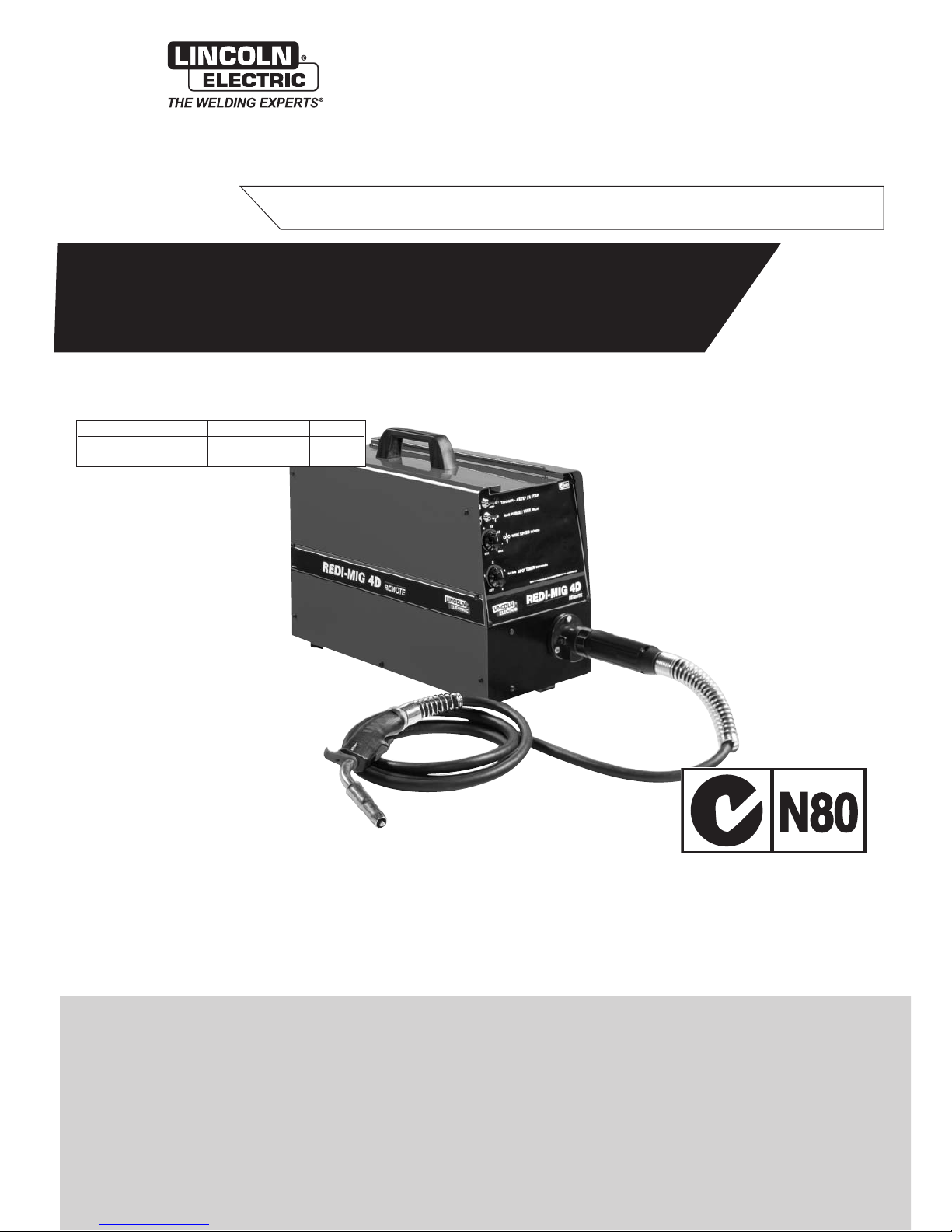
Part No. Code Description Volts
KA 1435
1568 REDI-MIG 4D 42
This manual applies to
REDI-MIG 4D Remote
Semi Automatic Wire Feeder
EMC Compliant
Page 2 REDI-MIG 4D IMA 600A
PROTECT YOURSELF AND OTHERS FROM POSSIBLE SERIOUS INJURY OR DEATH. READ AND UNDERSTAND
B
OTH THE SPECIFIC INFORMATION GIVEN IN THE OPERATING MANUAL FOR THE WELDER AND/OR OTHER
EQUIPMENT T
O BE USED AS WELL AS THE FOLLOWING GENERAL INFORMATION.
ARC WELDING SAFETY PRECAUTIONS
1. a. The electrode and work (or ground) circuits are
electrically “hot” when the welder is on. Do not touch
these “hot” parts with your bare skin or wet clothing.
Wear dry, hole-free gloves to insulate hands.
b. In semi-automatic and automatic wire welding, the
electrode, electrode reel, welding head and nozzle or
semi-automatic welding gun are also electrically “hot”.
c. Insulate yourself from work and ground using dry
insulation. When welding in damp locations, on metal
framework such as floors, gratings or scaffolds, and
when in positions such as sitting or lying, make certain
the insulation is large enough to cover your full area of
physical contact with work and ground.
d. Always be sure the work cable makes a good electrical
connection with the metal being welded. The
connection should be as close as possible to the area
being welded.
e. Ground the work or metal to be welded to a good
electr
ical (earth) ground.
f. Maintain the electrode holder, work clamp, welding
cable and welding machine in good, safe operating
condition. Replace damaged insulation.
g. Never dip the electrode holder in water for cooling.
h. Never simultaneously touch electrically “hot” parts of
electrode holders connected to two welders because
voltage between the two can be the total of the open
circuit voltage of both welders.
i. When working above floor level, protect yourself from
a fall should you get a shock.
j. Also see items 4c and 6.
2. a. Welding may produce fumes and gases hazardous to
health.
A
v
oid breathing these fumes and gases
.
When
welding, keep your head out of the fume. Use enough
ventilation and/or exhaust at the arc to keep fumes and
gases away from the breathing zone. When welding on
galv
anised, lead or cadmium plated steel and other
metals which produce toxic fumes, even greater care
must be taken.
b. Do not weld in locations near chlorinated hydrocarbon
vapours coming from degreasing, cleaning or spraying
operations. The heat and rays of the arc can react with
solv
ent v
apours to form phosgene, a highly toxic gas,
and other irritating products.
c.
Shielding gases used for arc welding can displace air
and cause injury or death. Always use enough
ventilation, especially in confined areas, to ensure
breathing air is safe.
d. Read and understand the manufacturer’ s instructions
f
or this equipment and the consumab
les to be used,
including the material safety data sheet (MSDS) and
follow your employer’s safety practices.
e. Also see Item 7b.
3. a. Use a shield with the proper filter and cover plates to
protect your eyes from sparks and the rays of the arc
when welding or observing open arc welding.
Headshield and filter lens should conform to AS
1674.2-2003 AS1337-1992 and AS1338-1992
standards.
b. Use suitable clothing made from durable flame
resistant material to protect your skin and that of your
helpers from the arc rays.
c. Protect other nearby personnel with suitable non
flammable screening and/or warn them not to watch
the arc or expose themselves to the arc rays or to hot
spatter or metal.
4. a. Remove fire hazards from the welding area. If this is
not possible, cover them to prevent the welding sparks
from starting a fire. Remember that welding sparks and
hot materials from welding can easily go through small
cracks and openings to adjacent areas. Have a fire
extinguisher readily available.
b. Where compressed gases are to be used at the job
site, special precautions should be used to prevent
hazardous situations. Refer to AS1674 Parts 1 & 2
“Safety in Welding and Allied Processes”, WTIA
Technical Note 7 “Health and Safety in Welding” and
the operating information for the equipment being
used.
c. When not welding, make certain no part of the
electrode circuit is touching the work or ground.
Accidental contact can cause overheating and create a
fire hazard.
d.
Do not heat, cut or w
eld tanks
, dr
ums or containers
until the proper steps have been taken to insure that
such procedures will not cause flammable or toxic
v
apours from substances inside
. These can cause an
e
xplosion e
v
en though the v
essel has been “cleaned”.
For information purchase AS 1674-1990.
e. Vent hollow castings or containers before heating,
cutting or welding. They may explode.
f
. Sparks and spatter are thrown from the welding arc.
W
ear oil free protectiv
e garments such as leather
glo
v
es
, hea
vy shir
t, cuffless trousers
, high shoes and
a cap over your hair. Wear ear plugs when welding out
of position or in confined places. Always wear safety
glasses with side shields when in a w
elding area.
g.
Connect the w
or
k cable to the work as close to the
welding area as possible. Work cables connected to
the building framework or other locations away from
the w
elding area increase the possibility of the welding
current passing through lifting chains
, cr
ane cab
les or
other alternate circuits. This can create fire hazards or
overheat lifting chains or cables until they fail.
h. Also see Item 7c.
ELECTRIC SHOCK can kill
FUMES AND GASES
can be dangerous
ARC RAYS can burn
WELDING SPARKS can
cause fire or explosion
IMA 600A REDI-MIG 4D Page 3
5. a. Use only compressed gas cylinders containing the
correct shielding gas for the process used and
properly operating regulators, designed for the gas
and pressure used. All hoses, fittings, etc. should be
suitable for the application and maintained in good
condition.
b. Always keep cylinders in an upright position and
securely chained to an undercarriage or fixed support.
c. Cylinders should be located :
• Away from areas where they may be struck or
subjected to physical damage.
• A safe distance from arc welding or cutting
operations and any other source of heat, sparks
or flame.
d. Never allow the electrode, electrode holder, or any
other electrically “hot” parts to touch a cylinder.
e. Keep your head and face away from the cylinder valve
outlet when opening the cylinder valve.
f. Valve protection caps should always be in place and
hand-tight except when the cylinder is in use or
connected for use.
g. Read and follow the instructions on compressed gas
cylinders and associated equipment, and AS 2030
Parts 1 & 2.
6. a. Turn off input power using the disconnect switch at the
fuse box before working on the equipment.
b. Install equipment in accordance with the SAA Wiring
Rules, all local codes and the manufacturer’s
recommendations.
c. Ground the equipment in accordance with the SAA
Wiring Rules and the manufacturer’s
recommendations.
7. a. Turn the engine off before troubleshooting and
maintenance work unless the maintenance
work requires it to be running.
b. Operate engines in open, well ventilated
areas or vent the engine exhaust fumes
outdoors.
c. Do not add fuel near an open flame,
welding arc or when the engine is running.
Stop the engine and allow it to cool before
refuelling to prevent spilled fuel from
vaporizing on contact with hot engine parts
and igniting. Do not spill fuel when filling
tank. If fuel is spilled, wipe it up and do not
start engine until fumes have been
eliminated.
d. Keep all equipment, safety guards, covers
and devices in position and in good repair.
Keep hands, hair, clothing and tools away
from V-belts, gears, fans and all other
moving parts when starting, operating or
repairing equipment.
e
. In some cases it may be necessary to
remo
ve safety guards to perform required
maintenance. Remove guards only when
necessary and replace them when the
maintenance requiring their removal is
complete. Always use the greatest care
when working near moving parts.
f. Do not put your hands near the engine fan.
Do not attempt to override the governor or
idler by pushing on the throttle control rods
while the engine is running.
g. To prevent accidentally starting petrol
engines while turning the engine or welding
generator during maintenance work,
disconnect the spark plug wires, distributor
cap or magneto wire as appropriate.
h. To avoid scalding do not remove the
radiator pressure cap when the engine is
hot.
CYLINDER may explode
if damaged
FOR ELECTRICALLY
powered equipment
FOR ENGINE
powered equipment
HAVE ALL INSTALLATIONS, OPERATION, MAINTENANCE AND REPAIR WORK PERFORMED BY QUALIFIED PEOPLE
HO
W TO ORDER REPLACEMENT PARTS
To ensure that you receive the correct replacement part the following procedure should be followed:
1. Quote Serial Number and Code Number.
2. Quote the Description, Item Number and Parts List Number of the desired part. When ordering parts for items carrying brand
names of other companies, such as fan motors, drive shafts, etc., be sure to include the other company’s name and part number
and other rele
v
ant information.
3. Should the primary cord be damaged, a special cord is required, and is available from Lincoln Electric.
4. Parts should be ordered from Lincoln, its offices or the nearest Authorised Service Facilities. (The “Lincoln Service Directory”
listing these shops geographically is available on request.)
Note: “Hardware” in the Lincoln Parts Lists are not Lincoln stock items but can be obtained via the Authorised Service Facilities.
Component parts of assemblies such as stator coils or armature coils, etc., which require electrical testing or locating fixtures are not
considered replaceable items. This is to ensure that the customer receives parts which will keep the welder in the best operating condition.
BUY ONLY GENUINE REPAIR PARTS
For more detailed information it is strongly recommended that you purchase a copy of “Safety in Welding and Allied Processes AS1674
Parts 1 & 2” and WTIA Technical Note 7. All WTIA publications are available from the Welding Technology Institute of Australia, P.O. Box
6165, Silverwater NSW 2128. For copies of various Australian Standards contact your local S.A.A. office.

Page 4 REDI-MIG 4D IMA 600A
WELDING, EMF & PACEMAKERS
All welders should follow safe practices that minimise their
exposure to electric and magnetic fields (EMF).
F
or welders wearing implanted pacemakers, safe welding
practices are particularly important and additional procedures
should be followed by those who have decided to continue to
weld. (Hopefully in keeping with a doctor’s advice).
The following procedures will not eliminate exposure to EMF or
the possibility of arc welding having an effect on a pacemaker,
however if followed, they will significantly reduce exposure to
electric and magnetic fields. Electric and magnetic fields are
created any time electric current flows through a conductor,
however it is not clear whether such exposure affects ones health.
Some researchers have reported that exposure to EMF may
cause leukemia or other illnesses. These claims originally arose
in relation to high voltage electric power lines and are very much
in dispute in the medical and scientific arena, however the best
advice is to minimise your exposure to EMF to protect your health
should doctors eventually decide there is a risk.
There are four fundamental facts about EMF:
• With direct current (DC), the field strength is relatively
constant and does not change.
• With alternating current (AC), the field strength constantly
changes.
• The greater the current flow, i.e. the higher the amps, the
stronger the field created by the current
• The closer the conductor or electrical device is to the body,
the greater the exposure to the field.
Minimising exposure
All welders should use the following procedures to minimise EMF
exposure.
•
Route electrode or gun and w
or
k cab
les together
.
Secure
them with tape if possible.
•
Ne
v
er coil the electrode lead around your body.
•
Do not place y
our body between the electrode and work
cab
les
. If your electrode cable is on your right side the work
cable should also be on your right side.
• Connect the work cable to the work piece as close as
possible to the area being welded. (This is also a good
pr
actice to eliminate a common prob
lem on w
elding - a
poor work connection.
• Do not work next to the welding power source.
Welders with pacemakers
There is no question that the fields in arc welding can interfere
with a pacemakers function. Generally the interference does not
permanently damage the pacemaker. Once the wearer leaves the
arc welding environment or stops welding, the pacemaker returns
to normal functioning. The welding arc has little or no effect on the
operation of some pacemakers, especially designs that are bipolar or designed to filter out such interference.
F
or a welder or anyone working around electrical equipment the
selection of a pacemaker is very important. Get a doctor’s advice
about which pacemaker is the least sensitive to interference from
welding while still being medically suitable.
In addition to the normal safety precautions, the following
additional procedures should be adopted by welders with
pacemakers.
• Use gas welding when the application is suitable.
• Use the lowest current setting appropriate for the
application. Do not exceed 400 amps. Low current
(75-200 amps) direct current (DC) welding should be used
if arc welding is necessary. Do not TIG weld with high
frequency.
• Do not use repeated, short welds. Wait about ten seconds
between stopping one weld and starting the next. When
having difficulty starting an electrode, do not re-strike the
rod repeatedly.
• If you feel light headed, dizzy or faint, immediately stop
welding. Lay the electrode holder down so that it does not
contact the work and move away from any welding being
performed. Arrange your work in advance so that, if you
become dizzy and drop the electrode holder, the electrode
holder will not fall on your body or strike the work.
• Do not work on a ladder or other elevated position or in a
cramped, confined place.
• Do not work alone. Work only in the presence of an
individual who understands these precautions and the
possible effect welding may have on your pacemaker.
•
Do not w
or
k near spot w
elding equipment.
• If you have a pacemaker and wish to continue arc welding,
discuss this and any other questions you may have with
y
our ph
ysician and follow his or her advice.The doctor may
wish to contact the pacemaker manufacturer for a
recommendation. As mentioned before, the design of the
pacemaker significantly affects the degree to which it is
subject to interference from a welding circuit. Do not rely on
the f
act that y
ou kno
w another w
elder with a pacemaker
who has welded for years without experiencing a problem.
That w
elder and his or her pacemak
er ma
y be quite
different from you and your pacemaker.

Conformance
Products displaying the C-Tick mark are in conformity with
Australian/New Zealand requirements for Electromagnetic
Compatibility (EMC) according to standard AS/NZS “Industrial
scientific and medical (ISM) radio-frequency equipment Electromagnetic disturbance characteristics - Limits and methods
of measurement”.
Products displaying the CE mark are in conformity with European
Community Council Directive 89/336/EEC requirements for EMC
by implementing EN60974-10 “Arc Welding Equipment - Part 10:
Electromagnetic Compatibility (EMC) requirements”.
• manufactured in conformity with Australian/New Zealand
Standard (Emission):- AS/NZS 3652 ‘Electromagnetic
Compatibility - Arc Welding Equipment’ (Identical to and
reproduced from British Standard EN 50199)
Products are:
• for use with other Lincoln Electric/LiquidArc equipment.
• designed for industrial and professional use.
Introduction
All electrical equipment generates small amounts of
electromagnetic emission. Electrical emission may be transmitted
through power lines or radiated through space, similar to a radio
transmitter. When emissions are received by other equipment,
electrical interference may result. Electrical emissions may effect
many kinds of electrical equipment: other nearby welding
equipment, radio and TV transmitters and receivers, numerical
controlled machines, telephone systems, computers, etc. Be
aware that interference may result and extra precautions may be
required when a welding power source is used in a domestic
establishment.
Installation and Use
The purchaser/user is responsible for installing and using the
welding equipment according to the manufacturer’s instructions. If
electromagnetic disturbances are detected then it shall be the
responsibility of the purchaser/user of the welding equipment to
resolve the situation with the technical assistance of the
man
uf
acturer
. In some cases this remedial action may be as
simple as earthing (grounding) the welding circuit (see note
below). In other cases it could involve constructing an
electromagnetic screen enclosing the po
w
er source and the w
or
k
complete with associated input filters. In all cases
electromagnetic disturbances must be reduced to the point where
the
y are no longer troub
lesome
.
NOTE: The welding circuit may or may not be earthed for safety
reasons according to national codes. Changing the earthing
arr
angements should only be authorised by a person who is
competent to assess whether the changes increase the r
isk of
injury, eg. by allowing parallel welding current return paths which
may damage the earth circuits of other equipment.
Assessment of Area
Before installing welding equipment the purchaser/user shall
mak
e an assessment of potential prob
lems in the surrounding
area.
The following shall be taken into account:
a. Other supply cables, control cables, signalling and telephone
cables above, below and adjacent to the welding equipment;
b
.
Radio and tele
vision tr
ansmitters and receiv
ers;
c. Computer and other control equipment;
d. Safety critical safety equipment, eg. guarding of industrial
equipment;
e. The health of people around, eg. the use of pacemakers and
hear
ing aids;
f. Equipment used for calibration or measurement;
g. The immunity of other equipment in the environment. The
purchaser/user shall ensure that other equipment being used
in the environment is compatible. This may require additional
protection measures;
h. The time of the day that welding or other activities are to be
carried out.
The size of the surrounding area to be considered will depend on
the structure of the building and other activities that are taking
place. The surrounding area may extend beyond the boundaries
of the premises.
Methods of Reducing Emissions
Mains Supply
Welding equipment should be connected to the mains supply
according to the manufacturer’s recommendations.If interference
occurs, it may be necessary to take additional precautions such
as filtering the mains supply. Consideration should be given to
shielding the supply cable of permanently installed welding
equipment in metallic conduit or equivalent. Shielding should be
electrically continuous throughout its length. The shielding should
be connected to the welding power source so that good electrical
contact is maintained between the conduit and the welding power
source enclosure.
Maintenance of the Welding Equipment
The welding equipment should be routinely maintained according
to the manufacturer’s recommendations. All access and service
doors and covers should be closed and properly fastened when
the w
elding equipment is in operation. The welding equipment
should not be modified in any way except for those changes and
adjustment covered in the manufacturer’s instructions. In
par
ticular, the spark gaps of arc initiation and stabilising devices
should be adjusted and maintained according to the
manufacturer’s recommendations.
Welding Cables
The welding cables should be kept as short as possible and
should be positioned close together, running at or close to the
floor level.
Equipotential Bonding
Bonding of all metallic components in the welding installation and
adjacent to it should be considered. However, metallic
components bonded to the work piece will increase the risk that
the operator could receive a shock by touching these metallic
components and the electrode at the same time. The operator
should be insulated from all such bonded metallic components.
Earthing of the workpiece
Where the workpiece is not bonded to earth for electrical safety,
nor connected to earth because of its size and position, eg. ship’s
hull or building steelwork, a connection bonding the workpiece to
earth may reduce emissions in some, but not all instances. Care
should be taken to prevent the earthing of work pieces increasing
the r
isk of injur
y to users, or damage to other electrical
equipment. Where necessary, the connection of the workpiece to
earth should be made by direct connection to the workpiece, but
in some countries where direct connection is not permitted, the
bonding should be achieved by suitable capacitance, selected
according to national regulations
.
Screening and Shielding
Selective screening and shielding of other cables and equipment
in the surrounding area ma
y alleviate problems of interference.
Screening of the entire w
elding installation ma
y be considered f
or
special applications.*
Portions of the preceding text are extracted from:
• Australian/New Zealand standard AS/NZS 3652. permission to
reproduce has been g
r
anted b
y Standards Australia and
Standards New Zealand. For further explanation, reads should
be ref
erred to the standard itself
.
• British Standards Institution standard BS EN 50199: 1995.
Reproduced with permission of BSI under license number
2000SK0631.
Complete standards can be obtained from BSI
Customer Services, 389 Chiswick High Road, London W4 4AL,
United Kingdom.
(T
el +44 (0) 20 8996 9001).
Copyright of the above text is property of Standards Australia,
Standards New Zealand and British Standards Institution.
P
er
mission to reproduce the te
xt m
ust be obtained.
May ‘07
INSTRUCTIONS FOR ELECTROMAGNETIC COMPATIBILITY
This welding machine must be used by trained operators
onl
y. Read this manual carefully before attempting to use
the welding machine.
WARNING
Page 6 REDI-MIG 4D IMA 600A
Thank You
for selecting a QUALITY product by Lincoln Electric. We want you to
take pride in operating this Lincoln Electric Company product - as much
pride as we have in bringing this product to you!
Please Examine Carton and Equipment for Damage Immediately
When this equipment is shipped, title passes to the purchaser upon receipt b
y the carrier. Consequently, claims for
material damaged in shipment must be made by the purchaser against the transportation company at the time the
shipment is receiv
ed.
Please record your equipment identification information below for future reference. This information can be found
on your machine nameplate.
Model Name & Number
_______________________________________________
Code & Serial Number ________________________________________________
Date of Purchase ____________________________________________________
Whenever you request replacement parts or information on this equipment, always supply the information you
have recorded above.
Read this Operator’s Manual completely before attempting to use this equipment. Save this manual and keep it handy
for quick reference. Pay particular attention to the Safety Instructions we have provided for your protection. The level of
seriousness to be applied to each is explained below:
This statement appears where the information must be
followed exactly to avoid serious personal injury or loss of life.
WARNING
This statement appears where the information must be
followed to avoid minor personal injury or damage to this
equipment.
CAUTION

IMA 600A REDI-MIG 4D Page 7
Page
CONNECTION & OPERATION
Section 1 Description 8
Section 2 Rating 8
Section 3 Connections 8
Section 4 42V 50Hz Supply 8
Section 5 Control Panel 8
5.1
Wire Feed Speed Control 8
5.2 2 Step/4 Step Operation 8
5.3 Spot Welding 8
5.4 Gas Purge / Wire Inch 8
5.5 Burnback Control 8
Section 6 - Setting Up for Welding 9
Section 7 Welding 9
7.1 Changing Electrode Size and Type 9
7.2 Gun Tip 9
7.3 Adjusting Spool Tension 9
7.4 Liner Removal, Installation & Trimming Instructions for 10
REDI-MIG 2 Torch
Section 8 Ground Test Procedure 10
Section 9 PARTS LISTS REDI-MIG 4D Remote Wire Feeder 11
WIRING DIAGRAM REDI-MIG 4D Remote Wire Feeder 15
WIRE DRIVE ASSEMBLY 16
INDEX

Section 1 - Description
The REDI-MIG 4D Wire Feeder has a drive plate with four
drive rolls (all driven). It has been designed for use with
continuous electrodes with or without an externally applied
shielding gas. The welding gun must have a standard
“Euro” connector at the machine end. Input power
requirements are 42V AC 50Hz, which is supplied by the
REDI-MIG Remote power source. The units also feature
electrical contacts to allow the power source output to be
switched on and off, so that the gun and electrode will be
electrically “cold” when not in use. A gas solenoid is
provided to automatically control gas flow when shielding
gas is used.
Front panel controls are:
(a) Electrode wire feed speed control
(b) Spot weld time switch and control
(c) “2 Step/4 Step” trigger mode switch for gun trigger
(d)
“Gas Purge”/”Wire Inch” toggle switch
(e) A burnback control is situated in the wire bay area
Section 2 - Rating
Wire feeder rating is 400 amps max. at 60% duty cycle or
300 amps max. at 100% duty cycle. The current and duty
cycle must also be within the rated capacity of the power
source.
The wire feeder may be used with 0.6mm to 1.2mm dia.
solid wire, 1.0mm to 1.6mm aluminium wire and up to
1.6mm flux cored electrodes on standard spools (with a
50mm I.D. boss, 300mm max. O.D. and 15kg max.
capacity). Wire feed speed range is approximately 1 to 20
metres/min. (40 to 790 inch/mind.)
Weight is approximately 27kg.
Section 3 - Connections
The wire feeder is connected electrically to the power
source by two cables.
1. The control/power cable includes a 4-pin amphenol plug
and carr
ies the f
ollo
wing circuits:
a) 42V, 50Hz AC control power (isolated from chassis)
b)
A closing contact to s
witch on the w
elders output
(provides 42V switched on pins ‘a’ and ‘b’)
c)
42V
, 50Hz AC control power (isolated from chassis)
d) Earth. Chassis of power source to chassis of wire
feeder
2. The welding power cable from the power source’s
“electrode”* output.
* Electrode polarity is determined by the wire and
w
elding process
.
Refer to the appropriate handbook
or the electrode packaging.
For gas shielded processes, connect the gas hose
(included with standard input cable assembly) to the gas
bottle regulator
.
Incoming gas pressure m
ust not e
xceed
1000kPa and a gas regulator must be used.
Connect a suitab
le welding gun and cable assembly to the
“Euro” connector on the front panel.The REDI-MIG Remote
power sources are supplied with REDI-MIG guns as
follows:
Mac
hine
T
or
ch
REDI-MIG 255 Remote REDI-MIG 240
REDI-MIG 325 Remote REDI-MIG 360
Section 4 - 42V AC 50Hz Supply
If the welding power source to be used does not have a 42V
AC auxiliary supply, a step-down transformer will be
required. This transformer must have a minimum rating of
220VA and an output voltage of 42V + 5% 50Hz AC.
Contact Lincoln for further details required.
Section 5 - Control Panel
5.1
Wire Feeder Speed Control
Use this control to adjust the speed at which the electrode
wire feeds when welding. This is in effect a current control
as the power source will deliver the current necessary to
melt the wire. The higher the speed, the more current will
be required. Wire feed speed range is approximately 1 to 20
metres/min. (40 to 790 inch min.)
Operation of the gun trigger, switches the wire feed motor
on and off, depending upon the trigger mode setting. The
wire feed motor is dynamically braked to minimise wire
overrun after welding has ceased.
Welding voltage is available immediately the gun trigger is
operated. When welding is stopped there is a delay to allow
the electrode to burn back slightly and prevent sticking in
the crater.
5.2 2 Step/4 Step Operation
A two position toggle switch on the front panel provides two
modes of operation of the gun trigger. In 2 Step mode, the
gun trigger is pressed to start welding and released to stop.
In 4 Step mode, pressing the gun trigger only operates the
gas solenoid, allowing shielding gas to flow. Releasing the
trigger activates the contactor which starts the wire feed
motor and connects welding current to the wire so that
welding may commence. To stop welding, the trigger must
again be operated; pressing it stops the wire feed, activates
the burn back time delay and opens the contactor after the
pre-set burn back time. Releasing the trigger stops the gas
flow.
T
o recommence w
elding, the abo
v
e cycle m
ust be
repeated.
5.3 Spot Welding
In spot welding mode, welding takes place for a pre-set
time and then stops automatically. Welding time is
adjustable between approx. 0.5 sec and 4 sec by operation
of the spot weld control on the front panel. There is a
positive click in the extreme anticlockwise position to
indicate that the spot w
eld f
eature is
“off
”.
5.4 Gas Purge / Wire Inch
Use the gas purge momentary toggle switch to operate the
gas solenoid to purge air from the hose after connecting a
new gas cylinder. Gas purge will only operate while the
toggle switch is held upwards.
Use this same toggle s
witch to oper
ate the wire f
eed motor
and
“cold”
inch the wire without oper
ating the po
wer source
contactor or gas solenoid, b
y pushing the toggle s
witch
do
wnw
ards
.
5.5 Burnback Control
This control is located in the wire feed bay. The burnback
control adjusts the time period from when the drive motor
stops until the power source and gas solenoid are switched
off. [Approx 0.1 seconds (when fully counterclockwise) to
approx 1.1 seconds (when fully clockwise)].
The purpose of the burnback control is to prevent the
electrode wire stic
king in the w
eld cr
ater at the finish of the
weld.
Page 8 REDI-MIG 4D IMA 600A
CONNECTION & OPERATION
ELECTRIC SHOCK can kill
ARC RAYS can burn
 Loading...