

Page 1
Operator’s Manual
®
MINIFLEX
For use with machines having Product Numbers:
K3972-3, K2497-18
Register your machine:
www.lincolnelectric.com/register
Authorized Service and Distributor Locator:
www.lincolnelectric.com/locator
Save for future reference
Date Purchased
Code: (ex: 10859)
Serial: (ex: U1060512345)
IM10299 | Issue D ate Sep-16
© Lincoln Global, Inc. All Rights Reserved.
Need Help? Call 1.888.935.3877
to talk to a Service Representative
Hours of Operation:
8:00 AM to 6:00 PM (ET) Mon. thru Fri.
After hours?
Use “Ask the Experts” at lincolnelectric.com
A Lincoln Service Representative will contact you
no later than the following business day.
For Service outside the USA:
Email: globalservice@lincolnelectric.com
Page 2
THANK YOU FOR SELECTING
A QUALITY PRODUCT BY
LINCOLN ELEC TRIC.
PLEASE EXAMINE CARTON AND EQUIPMENT FOR
DAMAGE IMMEDIATELY
When this equipment is shipped, title passes to the purchaser
upon receipt by the carrier. Consequently, claims for material
damaged in shipment must be made by the purchaser against the
transportation company at the time the shipment is received.
SAFETY DEPENDS ON YOU
Lincoln arc welding and cutting equipment is designed and built
with safety in mind. However, your overall safety can be increased
by proper installation ... and thoughtful operation on your part.
DO NOT INSTALL, OPERATE OR REPAIR THIS EQUIPMENT
WITHOUT READING THIS MANUAL AND THE SAFETY
PRECAUTIONS CONTAINED THROUGHOUT. And, most importantly,
think before you act and be careful.
WARNING
This statement appears where the information must be followed
exactly to avoid serious personal injury or loss of life.
CAUTION
This statement appears where the information must be followed
to avoid minor personal injury or damage to this equipment.
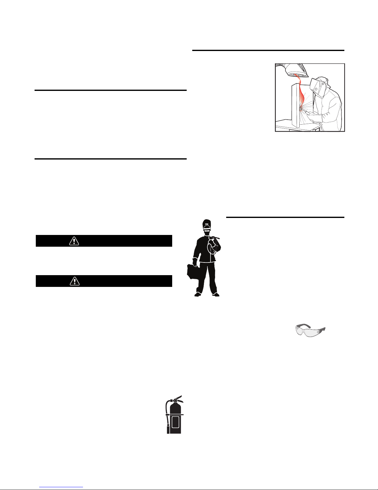
KEEP YOUR HEAD OUT OF THE FUMES.
DON’T get too close to the arc.
se corrective lenses if necessary
U
to stay a reasonable distance
away from the arc.
READ and obey the Safety Data
Sheet (SDS) and the warning label
that appears on all containers of
welding materials.
USE ENOUGH VENTILATION or
exhaust at the arc, or both, to
keep the fumes and gases from
your breathing zone and the general area.
IN A LARGE ROOM OR OUTDOORS, natural ventilation may be
adequate if you keep your head out of the fumes (See below).
USE NATURAL DRAFTS or fans to keep the fumes away
from your face.
If you de velop unusual symptoms, see your supervisor.
Perhaps the welding atmosphere and ventilation system
should be checked.
WEAR CORRECT EYE, EAR &
BODY PROTECTION
PROTECT your eyes and face with welding helmet
properly fitted and with proper grade of filter plate
(See ANSI Z49.1).
PROTECT your body from welding spatter and arc
flash with protective clothing including woolen
clothing, flame-proof apron and gloves, leather
leggings, and high boots.
PROTECT others from splatter, flash, and glare
with protective screens or barriers.
IN SOME AREAS, protection from noise may be appropriate.
BE SURE protective equipment is in good condition.
Also, wear safety glasses in work area
AT ALL TIMES.
SPECIAL SITUATIONS
DO NOT WELD OR CUT containers or materials which previously
had been in contact with hazardous substances unless they are
properly cleaned. This is extremely dangerous.
DO NOT WELD OR CUT painted or plated parts unless special
precautions with ventilation have been taken. They can release
highly toxic fumes or gases.
Additional precautionary measures
PROTECT compressed gas cylinders from excessive heat,
mechanical shocks, and arcs; fasten cylinders so they cannot fall.
BE SURE cylinders are never grounded or part of an
electrical circuit.
REMOVE all potential fire hazards from welding area.
ALWAYS HAVE FIRE FIGHTING EQUIPMENT READY FOR
IMMEDIATE USE AND KNOW HOW TO USE IT.
Safety 01 of 04 - 06/15/2016
Page 3
SAFETY
WARNINGS
Read all instructions before using MINIFLEX
WARNING
Important safety instructions –
Save these instructions
When using an electrical appliance, basic precautions
should always be followed, including the following:
• The use of this machine in conjunction with the pick-up
of ingredients in weld fume has not been investigated
by CSA Group.
• This fume extraction unit shall NOT be used to pick up
anything that is hot or burning.
• Use only as described in this manual. Use only
manufacturer’s recommended attachments.
• Do not use with damaged cord or plug. If appliance is
not working as it should, has been dropped, damaged,
left outdoors, or dropped into water, return it to a
service center.
• Do not pull or carry by cord, use cord as a handle, close
a door on cord, or pull cord around sharp edges or
corners. Do not run appliance over cord. Keep cord
away from heated surfaces.
• Do not unplug by pulling on cord. To unplug, grasp the
plug, not the cord.
• Do not handle plug or appliance with wet hands.
• Do not put any object into openings. Do not use with
any opening blocked; keep free of dust, lint, hair, and
anything that may reduce air flow.
• Keep hair, loose clothing, fingers, and all parts of body
away from openings and moving parts.
• Turn off all controls before unplugging.
• Do not use to pick up flammable or combustible liquids,
such as gasoline, or use in areas where they may be
present.
• Connect to a properly grounded outlet only. See
Grounding Instructions.
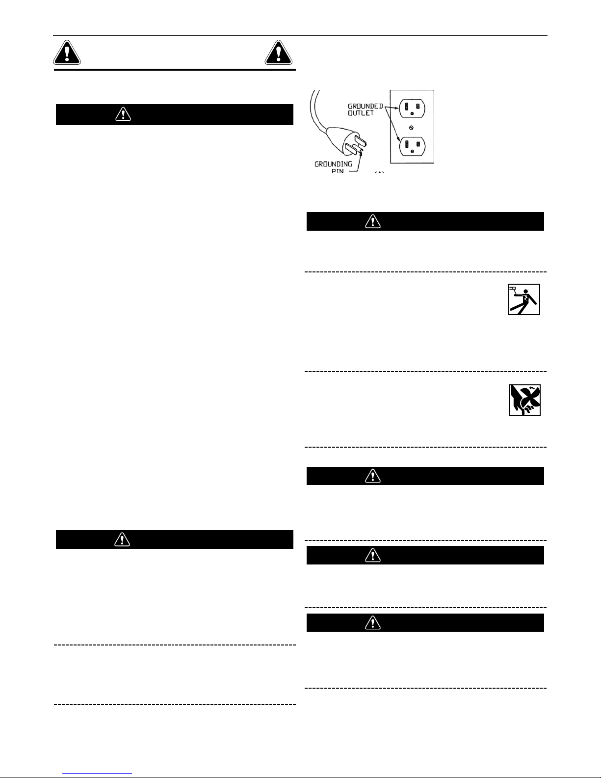
FIGURE 1
WARNING
The installer is responsible for following Federal, State
and Local safety codes and regulations.
ELECTRIC SHOCK can kill.
• Do not touch electrically live parts such as
internal wiring.
• Turn the input power off at the fuse box
before working on this equipment.
• Have a qualified person install and service this
equipment.
MOVING PARTS can injure.
• Do not operate with covers open or filter
removed.
• Keep away from moving parts.
Only qualified personnel should install, use or service this
equipment.
WARNING
To Reduce The Risk Of Electric Shock –
Do not use on wet surfaces.
Do not expose to rain. Store indoors.
WARNING
This appliance must be grounded. If it should
malfunction or breakdown, grounding provides a path of
least resistance for electric current to reduce the risk of
electric shock. This appliance is equipped with a cord
having an equipment-grounding conductor and
grounding plug. The plug must be inserted into an
appropriate outlet that is properly installed and grounded
in accordance with all local codes and ordinances.
This appliance is for use on a nominal 120-V circuit and
has a grounding attachment plug that looks like the plug
illustrated in FIGURE 1. Make sure that the appliance is
connected to an outlet having the same configuration as
the plug. No adaptor should be used with this appliance.
CAUTION
To Reduce The Risk Of Injury From Moving
Parts – Unplug Before Servicing
WARNING
TO REDUCE THE RISK OF
ELECTRIC SHOCK – UNPLUG BEFORE
CLEANING OR SERVICING.
Page 4
SECTION A:
WARNINGS
CALIFORNIA PROPOSITION 65 WARNINGS
Diesel Engines
Diesel engine exhaust and some of its constituents are known
to the State of California to cause cancer, birth defects, and other
reproductive harm.
Gasoline Engines
The engine exhaust from this product contains chemicals known
to the State of California to cause cancer, birth defects, or other
reproductive harm.
ARC WELDING CAN BE HAZARDOUS. PROTECT
YOURSELF AND OTHERS FROM POSSIBLE SERIOUS
INJURY OR DEATH. KEEP CHILDREN AWAY.
PACEMAKER WEARERS SHOULD CONSULT WITH
THEIR DOCTOR BEFORE OPERATING.
Read and understand the following safety highlights. For
additional safety information, it is strongly recommended
that you purchase a copy of “Safety in Welding & Cutting ANSI Standard Z49.1” from the American Welding Society,
P.O. Box 351040, Miami, Florida 33135 or CSA Standard
W117.2-1974. A Free copy of “Arc Welding Safety” booklet
E205 is available from the Lincoln Electric Company,
22801 St. Clair Avenue, Cleveland, Ohio 44117-1199.
BE SURE THAT ALL INSTALLATION, OPERATION,
MAINTENANCE AND REPAIR PROCEDURES ARE
PERFORMED ONLY BY QUALIFIED INDIVIDUALS.
SAFETY
1.d. Keep all equipment safety guards, covers
and devices in position and in good repair.
Keep hands, hair, clothing and tools away
from V-belts, gears, fans and all other
moving parts when starting, operating or
repairing equipment.
1.e. In some cases it may be necessary to remove safety guards to
perform required maintenance. Remove guards only when
necessary and replace them when the maintenance requiring
heir removal is complete. Always use the greatest care when
t
working near moving parts.
1.f. Do not put your hands near the engine fan. Do not attempt to
override the governor or idler by pushing on the throttle control
rods while the engine is running.
1.g. To prevent accidentally starting gasoline engines while turning
the engine or welding generator during maintenance work,
disconnect the spark plug wires, distributor cap or magneto wire
as appropriate.
1.h. To avoid scalding, do not remove the radiator
pressure cap when the engine is
hot.
ELECTRIC AND
MAGNETIC FIELDS MAY
BE DANGEROUS
2.a. Electric current flowing through any conductor
causes localized Electric and Magnetic Fields (EMF).
Welding current creates EMF fields around welding cables
and welding machines
FOR ENGINE POWERED
EQUIPMENT.
1.a. Turn the engine off before troubleshooting
and maintenance work unless the
maintenance work requires it to be running.
1.b. Operate engines in open, well-ventilated
areas or vent the engine exhaust fumes outdoors.
1.c. Do not add the fuel near an open flame
welding arc or when the engine is running.
Stop the engine and allow it to cool before
refueling to prevent spilled fuel from
vaporizing on contact with hot engine parts
and igniting. Do not spill fuel when filling
tank. If fuel is spilled, wipe it up and do not start engine until
fumes have been eliminated.
2.b. EMF fields may interfere with some pacemakers, and
welders having a pacemaker should consult their physician
before welding.
2.c. Exposure to EMF fields in welding may have other health effects
which are now not known.
2.d. All welders should use the following procedures in order to
minimize exposure to EMF fields from the welding circuit:
2.d.1. Route the electrode and work cables together - Secure
them with tape when possible.
2.d.2. Never coil the electrode lead around your body.
2.d.3. Do not place your body between the electrode and work
cables. If the electrode cable is on your right side, the
work cable should also be on your right side.
2.d.4. Connect the work cable to the workpiece as close as possible to the area being welded.
2.d.5. Do not work next to welding power source.
Safety 02 of 04 - 06/15/2016
Page 5
SAFETY
ELECTRIC SHOCK
CAN KILL.
3.a. The electrode and work (or ground) circuits are
electrically “hot” when the welder is on. Do
not touch these “hot” parts with your bare skin or wet clothing.
Wear dry, hole-free gloves to insulate hands.
3.b. Insulate yourself from work and ground using dry insulation.
Make certain the insulation is large enough to cover your full area
f physical contact with work and ground.
o
In addition to the normal safety precautions, if
welding must be performed under electrically
hazardous conditions (in damp locations or while
wearing wet clothing; on metal structures such as
floors, gratings or scaffolds; when in cramped
positions such as sitting, kneeling or lying, if there
is a high risk of unavoidable or accidental contact
with the workpiece or ground) use the following
equipment:
• Semiautomatic DC Constant Voltage (Wire) Welder.
• DC Manual (Stick) Welder.
• AC Welder with Reduced Voltage Control.
3.c. In semiautomatic or automatic wire welding, the electrode,
electrode reel, welding head, nozzle or semiautomatic welding
gun are also electrically “hot”.
3.d. Always be sure the work cable makes a good electrical
connection with the metal being welded. The connection should
be as close as possible to the area being welded.
3.e. Ground the work or metal to be welded to a good electrical (earth)
ground.
3.f. Maintain the electrode holder, work clamp, welding cable and
welding machine in good, safe operating condition. Replace
damaged insulation.
3.g. Never dip the electrode in water for cooling.
3.h. Never simultaneously touch electrically “hot” parts of electrode
holders connected to two welders because voltage
two can be the total of the open circuit voltage of both
welders.
3.i. When working above floor level, use a safety belt to protect
yourself from a fall should you get a shock.
between the
ARC RAYS CAN BURN.
4.a. Use a shield with the proper filter and cover plates to protect your
eyes from sparks and the rays of the arc when welding or
observing open arc welding. Headshield and filter lens should
conform to ANSI Z87. I standards.
4.b. Use suitable clothing made from durable flame-resistant material
to protect your skin and that of your helpers from the arc rays.
4.c. Protect other nearby personnel with suitable, non-flammable
screening and/or warn them not to watch the arc nor expose
themselves to the arc rays or to hot spatter or metal.
FUMES AND GASES
CAN BE DANGEROUS.
5.a. Welding may produce fumes and gases
hazardous to health. Avoid breathing these fumes and gases.
When welding, keep your head out of the fume. Use enough
ventilation and/or exhaust at the arc to keep fumes and gases
away from the breathing zone. When welding hardfacing
(see instructions on container or SDS) or on lead
or cadmium plated steel and other metals or
coatings which produce highly toxic fumes, keep
exposure as low as possible and within applicable
OSHA PEL and ACGIH TLV limits using local
exhaust or mechanical ventilation unless exposure
assessments indicate otherwise. In confined
spaces or in some circumstances, outdoors, a
respirator may also be required. Additional
precautions are also required when welding
on galvanized steel.
5. b. The operation of welding fume control equipment is affected by
various factors including proper use and positioning of the
equipment, maintenance of the equipment and the specific
welding procedure and application involved. Worker exposure
level should be checked upon installation and periodically
thereafter to be certain it is within applicable OSHA PEL and
ACGIH TLV limits.
5.c. Do not weld in locations near chlorinated hydrocarbon vapors
coming from degreasing, cleaning or spraying operations. The
heat and rays of the arc can react with solvent vapors to form
phosgene, a highly toxic gas, and other irritating products.
3.j. Also see It ems 6.c. and 8.
5.d. Shielding gases used for arc welding can displace air and
cause
injury or death. Always use enough ventilation, especially in
confined areas, to insure breathing air is safe.
5.e. Read and understand the manufacturer’s instructions for this
equipment and the consumables to be used, including the
Safety Data Sheet (SDS) and follow your employer’s safety
practices. SDS forms are available from your welding
distributor or from the manufacturer.
5.f. Also see item 1.b.
Safety 03 of 04 - 06/15/2016
Page 6
SAFETY
WELDING AND CUTTING
SPARKS CAN CAUSE
FIRE OR EXPLOSION.
6.a. Remove fire hazards from the welding area. If
this is not possible, cover them to prevent the welding sparks
rom starting a fire. Remember that welding sparks and hot
f
materials from welding can easily go through small cracks and
openings to adjacent areas. Avoid welding near hydraulic lines.
Have a fire extinguisher readily available.
6.b. Where compressed gases are to be used at the job site, special
precautions should be used to prevent hazardous situations.
Refer to “Safety in Welding and Cutting” (ANSI Standard Z49.1)
and the operating information for the equipment being used.
6.c. When not welding, make certain no part of the electrode circuit is
touching the work or ground. Accidental contact can cause
overheating and create a fire hazard.
6.d. Do not heat, cut or weld tanks, drums or containers until the
proper steps have been taken to insure that such procedures
will not cause flammable or toxic vapors from substances inside.
They can cause an explosion even though they have been
“cleaned”. For information, purchase “Recommended Safe
Practices for the Preparation for Welding and Cutting of
Containers and Piping That Have Held Hazardous Substances”,
AWS F4.1 from the American Welding Society
(see address above).
6.e. Vent hollow castings or containers before heating, cutting or
welding. They may explode.
6.f. Sparks and spatter are thrown from the welding arc. Wear oil free
protective garments such as leather gloves, heavy shirt, cuffless
trousers, high shoes and a cap over your hair. Wear ear plugs
when welding out of position or in confined places. Always wear
safety glasses with side shields when in a welding area.
6.g. Connect the work cable to the work as close to the welding area
as practical. Work cables connected to the building framework or
other locations away from the welding area increase the
possibility of the welding current passing through lifting chains,
crane cables or other alternate circuits. This can create fire
hazards or overheat lifting chains or cables until they fail.
6.h. Also see item 1.c.
CYLINDER MAY EXPLODE IF
DAMAGED.
7.a. Use only compressed gas cylinders containing
the correct shielding gas for the process used
and properly operating regulators designed for
the gas and pressure used. All hoses, fittings,
tc. should be suitable for the application and
e
maintained in good condition.
7.b. Always keep cylinders in an upright position securely chained to
an undercarriage or fixed support.
7.c. Cylinders should be located:
• Away from areas where they may be struck or subjected
to physical damage.
• A safe distance from arc welding or cutting operations
and any other source of heat, sparks, or flame.
7.d. Never allow the electrode, electrode holder or any other
electrically “hot” parts to touch a cylinder.
7.e. Keep your head and face away from the cylinder valve outlet
when opening the cylinder valve.
7.f. Valve protection caps should always be in place and hand tight
except when the cylinder is in use or connected for use.
7.g. Read and follow the instructions on compressed gas cylinders,
associated equipment, and CGA publication P-l, “Precautions for
Safe Handling of Compressed Gases in Cylinders,” available from
the Compressed Gas Association, 14501 George Carter Way
Chantilly, VA 20151.
FOR ELECTRICALLY
POWERED EQUIPMENT.
8.a. Turn off input power using the disconnect
switch at the fuse box before working on
the equipment.
8.b. Install equipment in accordance with the U.S. National Electrical
Code, all local codes and the manufacturer’s recommendations.
6.I. Read and follow NFPA 51B “Standard for Fire Prevention During
Welding, Cutting and Other Hot Work”, available from NFPA, 1
Batterymarch Park, PO box 9101, Quincy, MA 022690-9101.
6.j. Do not use a welding power source for pipe thawing.
8.c. Ground the equipment in accordance with the U.S. National
Electrical Code and the manufacturer’s recommendations.
Refer to
http://www.lincolnelectric.com/safety
for additional safety information.
Safety 04 of 04 - 06/15/2016
Page 7

INIFLEX
M
s a rule of thumb, for many mild steel electrode, if the air is visibly
A
®
ORTABLE WELDING FUME EXTRACTOR
P
clear and you are comfortable, then the ventilation is generally
adequate for your work. The most accurate way to determine if the
worker exposure does not exceed the applicable exposure limit for
compounds in the fumes and gases is to have an industrial hygienist
ake and analyze a sample of the air you are breathing. This is
t
particularly important if you are welding with stainless, hardfacing or
Special Ventilation products. All Lincoln MSDS have a maximum fume
guideline number. If exposure to total fume is kept below that
number, exposure to all fume from the electrode (not coatings or
plating on the work) will be below the TLV.
There are steps that you can take to identify hazardous substances in
your welding environment. Read the product label and material safety
data sheet for the electrode posted in the work place or in the
electrode or flux container to see what fumes can be reasonably
expected from use of the product and to determine if special
ventilation is needed. Secondly, know what the base metal is and
determine if there is any paint, plating, or coating that could expose
you to toxic fumes and/or gases. Remove it from the metal being
welded, if possible. If you start to feel uncomfortable, dizzy or
nauseous, there is a possibility that you are being overexposed to
fumes and gases, or suffering from oxygen deficiency. Stop welding
and get some fresh air immediately. Notify your supervisor and coworkers so the situation can be corrected and other workers can
avoid the hazard. Be sure you are following these safe practices, the
consumable labeling and MSDS to improve the ventilation in your
area. Do not continue welding until the situation has been corrected.
NOTE: The MSDS for all Lincoln consumables is available on Lincoln’s web-
site: www.lincolnelectric.com
Before we turn to the methods available to control welding fume
exposure, you should understand a few basic terms:
Natural Ventilation is the movement of air through the
workplace caused by natural forces. Outside, this is usually the
wind. Inside, this may be the flow of air through open windows
and doors.
Mechanical Ventilation is the movement of air through the
workplace caused by an electrical device such as a portable fan
or permanently mounted fan in the ceiling or wall.
Source Extraction (Local Exhaust) is a mechanical device used
to capture welding fume at or near the arc and filter contaminants out of the air.
The ventilation or exhaust needed for your application depends upon
many factors such as:
• Workspace volume
• Workspace configuration
• Number of welders
• Welding process and current
• Consumables used (mild steel, hardfacing, stainless, etc.)
• Allowable levels (TLV, PEL, etc.)
• Material welded (including paint or plating)
• Natural airflow
Your work area has adequate ventilation when there is enough
ventilation and/or exhaust to control worker exposure to hazardous
materials in the welding fumes and gases so the applicable limits for
those materials is not exceeded. See chart of TLV and PEL for Typical
Electrode Ingredients, the OSHA PEL (Permissible Exposure Limit), and
the recommended guideline, the ACGIH TLV (Threshold Limit Value),
for many compounds found in welding fume.
SAFETY
entilation
V
There are many methods which can be selected by the user to
rovide adequate ventilation for the specific application. The following
p
section provides general information which may be helpful in
evaluating what type of ventilation equipment may be suitable for
your application. When ventilation equipment is installed, you should
confirm worker exposure is controlled within applicable OSHA PEL
nd/or ACGIH TLV. According to OSHA regulations, when welding and
a
cutting (mild steels), natural ventilation is usually considered
sufficient to meet requirements, provided that:
1. The room or welding area contains at least 10,000 cubic feet
(about 22' x 22' x 22') for each welder.
2. The ceiling height is not less than 16 feet.
3. Cross ventilation is not blocked by partitions, equipment, or
other structural barriers.
4. Welding is not done in a confined space.
Spaces that do not meet these requirements should be equipped with
mechanical ventilating equipment that exhausts at least 2000 CFM of
air for each welder, except where local exhaust hoods or booths, or
air-line respirators are used.
Important Safety Note:
When welding with electrodes which require special
ventilation such as stainless or hardfacing (see
instructions on container or MSDS) or on lead or
cadmium plated steel and other metals or coatings which
produce hazardous fumes, keep exposure as low as
possible and below exposure limit values (PEL and TLV)
for materials in the fume using local exhaust or
mechanical ventilation. In con ned spaces or in some
circumstances, for example outdoors, a respirator may
be required if exposure cannot be controlled to the PEL
or TLV. (See MSDS and chart of TLV and PEL for Typical
Electrode Ingredients.) Additional precautions are also
required when welding on galvanized steel.
7
Page 8
INIFLEX
M
®
ORTABLE WELDING FUME EXTRACTOR
P
SAFETY
BIBLIOGRAPHY AND SUGGESTED READING
NSI, Standard Z49.1, Safety in Welding, Cutting and Allied
A
Processes. Z49.1 is now available for download at no charge at
NSI Z87.1, Practice for Occupational and Educational Eye and Face
A
Protection, American National Standards Institute, 11 West 42nd
Street, New York, NY 10036.
Arc Welding and Your Health: A Handbook of Health Information for
Welding. Published by The American Industrial Hygiene Association,
2700 Prosperity Avenue, Suite 250, Fairfax, VA 22031-4319.
NFPA Standard 51B, Cutting and Welding Processes, National Fire
Protection Association, 1 Batterymarch Park, P.O. Box 9146, Quincy,
MA 02269-9959.
OSHA General Industry Standard 29 CFR 1910 Subpart Q. OSHA
Hazard Communication Standard 29 CFR 1910.1200. Available from
the Occupational Safety and Health Administration at
http://www.osha.org or contact your local OSHA office.
The following publications are published by The American Welding
Society, P.O. Box 351040, Miami, Florida 33135. AWS publications
may be purchased from the American Welding society at
http://www.aws.org or by contacting the AWS at 800-443-9353.
LISTED BELOW ARE SOME TYPICAL INGREDIENTS IN WELDING ELECTRODES AND
THEIR TLV (ACGIH) GUIDELINES AND PEL (OSHA) EXPOSURE LIMITS
INGREDIENTS CAS No. TLV mg/m3PEL mg/m
Aluminum and/or aluminum alloys (as AI)***** 7429-90-5 1.0 15
Aluminum oxide and/or Bauxite***** 1344-28-1 1. 0 5**
Barium compounds (as Ba)***** 513-77-9 0.5 0.5
Chromium and chromium alloys or compounds (as Cr)***** 7440-47-3 0.5(b) 0.5(b)
Hexavalent Chromium (Cr VI) 18540-29-9 0.05(b) .005(b)
Copper Fume 7440-50-8 0.2 0.1
Cobalt Compounds 7440-48-4 0.02 0.1
Fluorides (as F) 7789-75-5 2.5 2.5
Iron 7439-89-6 10* 10*
Limestone and/or calcium carbonate 1317-65-3 10* 15
Lithium compounds (as Li) 554-13-2 15 10*
Magnesite 1309-48-4 10 15
Magnesium and/or magnesium alloys and compounds (as Mg) 7439-95-4 10* 10*
Manganese and/or manganese alloys and compounds (as Mn)***** 7439-96-5 0.02 5.0(c)
Mineral silicates 1332-58-7 5** 5**
Molybdenum alloys (as Mo) 7439-98-7 10 10
Nickel***** 7440-02-0 0.1 1
Silicates and other binders 1344-09-8 10* 10*
Silicon and/or silicon alloys and compounds (as Si) 7440-21-3 10* 10*
Strontium compounds (as Sr) 1633-05-2 10* 10*
Zirconium alloys and compounds (as Zr) 12004-83-0 5 5
http://www.lincolnelectric.com/community/safety/ or at the AWS
website http://www.aws.org.
AWS F1.1, Method for Sampling Airborne Particulates Generated by
Welding and Allied Processes.
AWS F1.2, Laboratory Method for Measuring Fume Generation Rates
nd Total Fume Emission of Welding and Allied Processes.
a
AWS F1.3, Evaluating Contaminants in the Welding Environment: A
Strategic Sampling Guide.
AWS F1.5, Methods for Sampling and Analyzing Gases from Welding
and Allied Processes.
AWS F3.2, Ventilation Guide for Welding Fume Control
AWS F4.1, Recommended Safe Practices for the Preparation for
Welding and Cutting of Containers and Piping That Have Held
Hazardous Substances.
AWS SHF, Safety and Health Facts Sheets. Available free of charge
from the AWS website at http://www.aws.org.
3
Supplemental Information:
(*) Not listed. Nuisance value maximum is 10 milligrams per cubic
meter. PEL value for iron oxide is 10 milligrams per cubic meter.
TLV value for iron oxide is 5 milligrams per cubic meter.
(**) As respirable dust.
(*****) Subject to the reporting requirements of Sections 311, 312,
and 313 of the Emergency Planning and Community Rightto-Know Act of 1986 and of 40CFR 370 and 372.
(b) The PEL for chromium (VI) is .005 milligrams per cubic meter as
an 8 hour time weighted average. The TLV for water-soluble
chromium (VI) is 0.05 milligrams per cubic meter. The TLV for
insoluble chromium (VI) is 0.01 milligrams per cubic meter.
(c) Values are for manganese fume. STEL (Short Term Exposure
Limit) is 3.0 milligrams per cubic meter. OSHA PEL is a ceiling
value.
(****) The TLV for soluble barium compounds is 0.5 mg/m
TLV and PEL values are as of October 2013. Always check Safety
Data Sheet (SDS) with product or on the Lincoln Electric website at
http://www.lincolnelectric.com
8
3
.
Page 9

INIFLEX
M
®
ORTABLE WELDING FUME EXTRACTOR
P
Page
Installation
General Description.................................................................................................10
Technical Specifications..........................................................................................10
Installation ...............................................................................................................11
Operation
Safety Precautions ..................................................................................................11
Recommended Uses...............................................................................................11
Operating Instructions .............................................................................................12
Maintenance .................................................................................................................14
Troubleshooting Guide ...............................................................................................17
Accessories..................................................................................................................18
TABLE OF CONTENTS
Wiring Diagram ............................................................................................................19
Parts List ........................................................................................................parts.lincolnelectric.com
Content/details may be changed or updated without notice. For most current Instruction Manuals, go to
parts.lincolnelectric.com.
Page 10

INSTALLATIONMINIFLEX®PORTABLE WELDING FUME EXTRACTOR
GENERAL DESCRIPTION
The MINIFLEX®is a portable, high vacuum welding fume extractor
esigned for the removal and filtration of welding fumes from light
d
duty welding applications. Its compact size permits the MINIFLEX to
be used in confined spaces and other locations that are not
accessible with other welding fume extractors.
The convenient automatic start/stop function can extend the life of the
motor brushes and reduces energy consumption. (Note: welding
current must be at least 50 amps to activate sensor). The optional
wall mounting bracket allows the unit to be mounted to a wall, freeing
up floor space.
The MINIFLEX can be completely disassembled in a matter of minutes
for cleaning and maintenance.
• 8 ft. (2.5 m) extraction hose with 1-3/4 in. (45mm) I.D.
hose adapter.
• Two sets of seals and carbon brushes.
The MINIFLEX is not supplied with a nozzle. Nozzles and extra hoses
can be ordered separately. The recommended nozzles and hoses are:
• Extraction Nozzles: EN 20 (K2389-5)
• Nozzle Kits: NKT or NKC (K2389-3, K2389-4)
• Fume Exhaust Guns
• Extraction Hoses:
- 8 ft. (2.5m) long x 1-3/4 in. (45mm) I.D. (K2389-9)
- 16 ft. (5m) long x 1-3/4 in. (45mm) I.D. (K2389-8)
• Hose-to-Hose Adapter (K2389-10)
• Hose Connection Outlet (K2389-2)
TECHNICAL
SPECIFICATIONS
GENERAL
NPUT VOLTAGE
I
RATED CURRENT DRAW 120V - 12.0A
POWER RATING 2.4 HP (1.2 HP PER MOTOR)
OPERATING SOUND LEVEL < 80 DB(A)
FILTER TYPE
STAGE ONE SEPARATE MESH SCREEN
STAGE TWO INTEGRATED MESH/SCREEN
STAGE THREE LONGLIFE-H™ PRETREATED
STAGE THREE SURFACE AREA 118 SQ. FT. (11 M2)
STAGE FOUR (OPTIONAL) ACTIVATED CARBON FILTER
STAGE FIVE HEPA (HIGH EFFICIENCY
AMBIENT CONDITIONS
MINIMUM TEMPERATURE 40ºF (5ºC)
MAXIMUM TEMPERATURE 104ºF (40ºC)
MAXIMUM RELATIVE HUMIDITY 80%
20V, 1Ph, 50-60Hz
1
230V, 1Ph, 50-60Hz
230V - 7.5A
PRE-FILTER
PRE-SEPARATOR
CELLULOSE FILTER
PARTICULATE AIR) FILTER
(2)
See Accessories section for more information.
Note: Recommended maximum hose length is 24 ft. (7.5m) on extraction side
of unit.
OPERATING CAPACITY
EXTRACTOR TYPE HIGH VACUUM, LOW VOLUME
AIRFLOW RATE LOW MODE: 95 CFM (161 M3/HR)
HIGH MODE: 108 CFM (183 M3/HR)
PHYSICAL DIMENSIONS
HEIGHT 29.0” (737 MM)
WIDTH 15.6” (395 MM)
DEPTH 16.7” (423 MM)
INLET/OUTLET OUTER DIAMETER 1-3/4” (45 MM)
WEIGHT 40 LBS. (18 KG)
(1)
Particle size: 0.3 µm. Testing method: Flat-sheet tested according to
EN 1822-3:2009 @ 190 m
EN 1822-2:2009.
(2)
Meets Integral Collection Efficiency Value for Filter Class E12 per
EN 1822-1:2009.
NOTE: Technical specifications are subject to change without prior notice.
Specifications and guarantees a re valid only when specified
replacement parts and filters are used.
3
/h with test aerosol generated according to
10
Page 11

INSTALLATIONMINIFLEX®PORTABLE WELDING FUME EXTRACTOR
INSTALLATION
INIFLEX UNIT MUST BE KEPT 6 INCHES FROM THE
M
WALL.
WARNING
The installer is responsible for following Federal, State
and Local safety codes and regulations.
ELECTRIC SHOCK can kill.
• Do not touch electrically live parts such as
internal wiring.
• Turn the input power off at the fuse box before
working on this equipment.
• Have a qualified person install and service this
equipment.
MOVING PARTS can injure.
• Do not operate with covers open or filter
removed.
• Keep away from moving parts.
Only qualified personnel should install, use or service this
equipment.
WARNING
RECOMMENDED USES
Read and understand this entire section before operating
your MINIFLEX.
CAUTION
This product is intended for commercial use
WARNING
Always operate this equipment with the filters installed
and covers in place as these provide maximum
protection from moving parts and insure proper vacuum
operation and cooling air flow.
The MINIFLEX is a portable, high vacuum welding fume extractor
designed for the removal and filtration of welding fumes released
from the following welding processes:
• MIG/MAG solid wire (GMAW)
• MIG/MAG flux cored wire (FCAW)*
• Stick welding (SMAW)
• TIG (GTAW) welding
*For light duty flux-cored applications only.
K3972-3: Requires 115V AC, single phase, 60Hz
grounded receptacle suitable for 15 amp service.
CONNECT ONLY TO A DEDICATED INDIVIDUAL
BRANCH CIRCUIT.
K2497-18: Requires 230V AC, single phase, 50Hz
grounded receptacle suitable for 7.5 amp service.
WARNING
NEVER USE the product for extracting and/or filtering
fumes and/or gases that are released from the following
processes:
• Welding applications with intensive use of anti-spatter
spray, paste or solution.
• Autogenic or plasma cutting spray/molten metal.
• Arc-air gouging.
• Welding that produces the release of a dense oil mist.
• Paint spraying.
• Extraction of hot gases [more than 104° F (40° C)].
• Extraction of aggressive fumes (such as acids).
• Grinding aluminum and magnesium.
• Flame spraying.
• Extraction of cement, saw dust, wood dust, etc.
• Extracting cigarettes, cigars, tissues and other burning
particles, objects and acids.
• Any dangerous situations where there is a risk of an
explosion or fire.
Note: The MINIFLEX does not filter any shielding gases. Gases pass through
the filter. MINIFLEX used with optional carbon filter may reduce vapors
and gases.
11
Page 12

OPERATING
INSTRUCTIONS
The MINIFLEX provides enough suction for one fume gun or small
uction nozzle. Do not attach more than one fume gun or suction
s
nozzle to the MINIFLEX unit.
1. Connect the extraction hose at one side to the air
inlet of the machine (Figure 3, Item A) and at the
other side to the welding torch or small suction
ozzle.
n
2. Lay the work cable of the welding machine into the
slot on top of the machine (Figure 4, Slot) (when
using Automatic Start/Stop mode).
3. Start up the machine by pressing the switch, located
on the side of the machine.
4. At the top of the unit, there is a High/Low button and
an Automatic Start/Stop Button (See Manual Vs.
Automatic Start/Stop Operation for further
instructions).
OPERATIONMINIFLEX®PORTABLE WELDING FUME EXTRACTOR
FIGURE 3
Recommended Positioning: Upright
For optimal performance, unit is designed to operate in upright
position.
WARNING
If unit is operated in an upright or horiz ontal position, air
inlet and outlet (Figure 3, Items A and B) must be free
from obstruction.
12
Page 13

OPERATIONMINIFLEX®PORTABLE WELDING FUME EXTRACTOR
A
CB
Check
Filter
Manual
A
uto
Low
H
igh
Check Brushes
Check
Filter
Manual
Auto
Low
High
Check Brushes
S3 S2 S1
HIGH AND LOW MODE
In high mode, both motors are working at 100% capacity, extracting
08 CFM (183 m
1
capacity, extracting 95 CFM (161 m
3
hr). In low mode, both motors are working at 88%
/
3
/hr).
MANUAL VS. AUTOMATIC START/STOP OPERATION
Use the Automatic Start/Stop feature to extend the life of the carbon
brushes.
In the "auto" setting (see Figure 4, item S2), the unit automatically
starts and stops when the work cable of the welding machine is
positioned in the slot located on top of the machine. See Figure 4.
The unit continues to operate for 15 seconds after welding is
completed before automatically shutting off.
In the manual setting, the unit runs continuously.
FIGURE 4
Worn Carbon Brushes Early Warning System Operation
S1S2
Slot
The worn carbon brushes warning system will inform the user when
90% of the carbon brushes have been used (equals approximately
750 hours motor running time). The unit will indicate this condition
with the Low and High speed LED’s blinking alternately with a
sequence of one second on and one second off. This indicator does
not affect the performance of the unit, but merely indicates that
maintenance should be performed.
After the carbon brushes have been replaced, the warning system is
reset by pressing buttons Low/High (S1) and Manual/Auto (S2) simultaneously and holding for five seconds. See Figure 5.
Total System Airflow / Static Pressure Control System*
This feature allows the user to check the extraction performance of
he unit. In order to check this performance (Flowcheck), follow the
t
procedure indicated below:
Flowcheck tests for a minimum airflow of approximately 60 CFM.
Flowcheck Procedure
1. Remove all connected apparatus such as hoses, nozzles, etc. from
inlet and outlet.
2. Switch unit to “On”, main switch O/I.
3. When unit starts running press and release the Low/High (S1)
button on the panel until the unit stops running.
4. Press and hold the “Check Filter” (S3) switch for five seconds.
5. Unit will automatically start in “High” speed mode and runs for
about 10 seconds.
6. The software checks the static pressure switch S4 (not visible,
switch is mounted on the circuit board).
7. When S4 = “open”, unit stops and goes to “Off” mode and the
“check filter” LED remains off. This indicates that the system
airflow is acceptable (above 60 CFM).
8. When S4 = “closed”, unit stops and goes to “Off” mode and the
“check filter” LED flashes with the frequency of one second on /
one second off. This indicates that the extraction volume is less
than 60 CFM.
9. Reset by pressing and holding S2 and S3 for five seconds.
In the case that the indicator communicates that the unit is extracting
less than 60 CFM, proceed as follows to find the filter resistance that
is causing this low airflow:
A. Check condition of pre-filter (Perform Flowcheck Procedure
without pre-filter to check if this is the cause of the low airflow).
Recommended Action: Wash or replace if necessary.
B. Check condition of the main filter (Perform Flowcheck Procedure
without main filter to check if this is the cause of low airflow).
Recommended Action: Replace if necessary.
C. Check condition of the HEPA post filter (Perform Flowcheck
Procedure without HEPA post filter to check if this is the cause of
the low airflow).
Recommended Action: Replace if necessary.
FIGURE 5
13
Page 14

MAINTENANCEMINIFLEX®PORTABLE WELDING FUME EXTRACTOR
B
C
H
A
E
G
F
D
MAINTENANCE
WARNING
ELECTRIC SHOCK can kill.
Unplug MINIFLEX before changing filter or
replacing carbon brushes.
Service and Repair should only be performed
y Lincoln Electric Factory Trained Personnel.
b
Unauthorized repairs performed on this
equipment may result in danger to the
technician and machine operator and will invalidate your
factory warranty. For your safety and to avoid Electrical
Shock, please observe all safety notes and precautions
detailed throughout this manual.
• The steel collection pan should be inspected, cleaned
and emptied on a monthly basis.
• The pre-separator (located on the bottom of the main
filter) should be inspected and cleaned on a monthly
basis, using an industrial vacuum cleaner.
• The pre-filter should be inspected and cleaned on a bimonthly basis, using compressed air or an industrial
vacuum cleaner.
• Frequency of cleaning and emptying depends on a
number of factors such as the type of welding process
and the frequency of use.
• The main filter should be checked every month to
ensure that there is no damage.
• The seals of the main filter should be checked every
12 months.
• When fume extractor is not in use, wrap cord and place
in the handle opening. Store fume extractor in a dry
place.
• When fume extractor is in use, take precaution that the
cord is protected from damage and not a tripping
hazard.
Refer to Figure 6 for the following instructions.
1. Remove electrical cord of MINIFLEX unit from electrical outlet.
2. Loosen the side clips (A).
3. Remove the top cover (B) from the machine.
4. Remove LongLife-H Filter (C) by lifting the filter out of the bottom
compartment of the unit.
5. Remove pre-filter (H)
6. Empty the collection pan (D) and dispose of waste properly*.
7. Replace the pre-filter and the LongLife-H Filter to the bottom unit
and reattach top cover by fastening the side clips (A).
*Check with local authorities for regulations governing the proper
disposal of used filters and particulate matter.
FIGURE 6
A. Side Clips
B. Top Cover
C. LongLife-H Filter
. Main Filter Seals
D
E. Outlet Cover
F. HEPA Filter
G. Carbon Brushes
H. Pre-filter
WARNING
The particulate matter collected in the unit may be
dangerous to your health. Take necessary precautions so
that you and your fellow workers do not breathe dust and
particulate. Wear a suitable respirator when disposing of
the particulate. Follow local Environmental regulations
for disposal of filters and particulate matter.
The main LongLife-H filter and the HEPA filter cannot be cleaned and
therefore they have to be replaced periodically. It is recommended to
replace all filters at the same time.
WARNING
A saturated filter often contains dust and dirt particles
which could form a health hazard upon inhalation. When
replacing the filters, always wear a high-quality and
approved face mask or respirator. Wrap the filters in a
properly closed plastic bag and dispose of it in
compliance with local regulations.
Replace the filters in case of damage or when the extraction capacity
has become insufficient due to the amount of particulate in the filter.
Periodic check of the filters is required to maintain optimal
performance and life of unit. Filter performance/life is dependent on
variables such as:
- Welding application/processes
- Oil involved in weld processes
- Dust/grinding particulate
- Proper usage and maintenance
Note: There is no filter clog indicator on this machine.
14
Page 15

MAINTENANCEMINIFLEX®PORTABLE WELDING FUME EXTRACTOR
A
B
Replacing/Cleaning the Pre-filter
1. Remove electrical cord of MINIFLEX unit from electrical outlet.
2. Loosen the side clips (A).
. Remove the top cover (B) from the unit.
3
4. Remove LongLife-H Filter (C).
5. Remove the pre-filter (H).
6. Clean pre-filter with industrial vacuum cleaner or replace if necessary. Use caution and proper personal protection equipment when
cleaning pre-filter.
7. Reposition the pre-filter (H) and LongLife-H™ Filter (C) and
reassemble unit.
Replacing the LongLife-H Filter and Integrated Aluminum
Mesh Pre-filter
1. Remove electrical cord of MINIFLEX unit from electrical outlet.
2. Loosen the side clips (A).
3. Remove the top cover (B) from the machine.
4. Remove LongLife-H Filter (C).
5. Check the main filter seals (D) before replacing the filter. If the
seals need to be replaced, contact your Lincoln Electric
representative.
6. Place the new filter (mesh pre-separator side down) into the bottom section and reassemble unit.
Replacing the HEPA Filter
1. Remove electrical cord of MINIFLEX unit from electrical outlet.
2. Remove the outlet cover (E) by loosening the two screws.
3. Remove the HEPA filter (F).
4. Place a new HEPA filter in the correct position (open side at the
top).
5. Remount the outlet cover by fastening the two screws. Make sure
that the outlet cover is in the right position; the open side of the
HEPA filter should correspond with the smallest opening of the outlet cover.
CAUTION
ATTENTION: Removing the HEPA filter will cause the
seals to deform. For this reason, never replace an old
HEPA filter with a used HEPA filter, but always replace it
with a new one.
Replacing the Carbon Filter (if applicable)
1. Remove electrical cord of MINIFLEX unit from electrical outlet.
2. Loosen the side clips (A).
3. Remove the top cover (B) from the machine.
4. Place carbon filter directly on top of LongLife-H Filter, either side up.
5. Replace top cover (B).
CARBON BRUSHES
The carbon brushes in both motors should be replaced after
approximately 750 hours motor running time (see Worn Carbon
Brushes Early Warning System Operation section for more
nformation).
i
CAUTION
arbon brush life depends on how unit is operated, i.e.
C
continuous operation or automatic start/stop mode. If
carbon brushes are not replaced, damage to motors
may result.
ote: Two sets of carbon brushes and motor seals are included with unit.
N
Carbon Brush Replacement
1. Remove electrical cord of MINIFLEX unit from electrical outlet.
2. Remove top cover (B) of MINIFLEX unit by releasing the side clips
(A) on both sides of unit. (See Figure 7)
3. To remove the housing plate (C) at bottom of top cover (See Figure
8), place top cover (B) with housing plate facing upward. Remove 8
screws (D) holding the housing cover plate using a torx head
screwdriver. Remove two nuts (E) holding the housing cover plate
in place. A 3/8” socket is required. After removing 8 screws and 2
nuts, use a flat blade screwdriver to remove motor cover plate. (C)
CAUTION
To avoid motors from dislodging, the MINIFLEX top
cover (B) must remain facing upward after removing
housing cover plate.
4. Slowly pull one motor (F) out at a time, until sufficient room is
allowed to remove and inspect carbon brushes (G).
5. Disconnect white, green and black wires from each motor connection terminal.
6. Follow carbon brush replacement on next page.
7. Reposition motors and reattach housing cover plate.
8. Place top cover on MINIFLEX unit using the two side clips.
9. Operate unit to make sure carbon brushes have been properly
installed.
FIGURE 7
15
Page 16

INIFLEX
E
D
C
F
G
M
®
ORTABLE WELDING FUME EXTRACTOR
P
FIGURE 8
MAINTENANCE
16
Page 17

INIFLEX
M
®
ORTABLE WELDING FUME EXTRACTOR
P
TROUBLESHOOTING GUIDE
ervice and Repair should only be performed by Lincoln Electric Factory Trained Personnel. Unauthorized repairs performed on
S
this equipment may result in danger to the technician and machine operator and will invalidate your factory warranty. For your
safety and to avoid ELECTRICAL SHOCK, please observe all safety notes and precautions detailed throughout this manual.
PROBLEMS / SYMPTOM(S) POSSIBLE CAUSE(S) RECOMMENDED COURSE(S) OF ACTION
TROUBLESHOOTING
MOTOR DOES NOT START.
POOR SUCTION.
Ensure 120 VAC 60Hz (K3972-
3), 230 VAC 50Hz (K2497-18),
Verify 120 VAC 60Hz (K3972-3), 230 VAC 50Hz (K2497-18),
input power at the machine.
input power is available.
Circuit breaker tripped. Reset circuit breaker.
Carbon brushes worn. Check brushes, replace if necessary.
Unit is in OFF mode. Press and release Low/High button.
Leakage. Check hose connections and integrity.
Filter dirty. Replace both LongLife-H Filter and HEPA filter.
Pre-filter dirty. Check pre-filter and replace or clean using an industrial vacuum
cleaner. Use caution and proper personal protection equipment
when cleaning pre-filter.
Improper application. Check hose diameter and maximum length 24 ft. (7.5 m), check
filter for oily conditions.
Brushes worn in one of the
Contact your local Lincoln Authorized Field Service Facility.
motors.
UNIT WILL NOT SENSE
CURRENT.
UNIT AUTOMATICALLY CYCLES
BETWEEN LOW AND HIGH
SPEEDS.
If for any reason you do not understand the test procedures or are unable to perform the tests/repairs safely, contact your
Lincoln Authorized Service Facility for technical troubleshooting assistance before you proceed.
WWW.LINCOLNELECTRIC.COM/LOCATOR
Welding current too low. Loop cable two or three times on current sensor.
Unit is in OFF mode. Press and release Low/High button.
Loose connections. Check connections from PC board to motors.
Control panel/PC board
Replace control panel and PC board.
damaged.
17
Page 18

ACCESSORIES
The following accessories are available for your MINIFLEX Portable
ume Extractor from your local Lincoln Electric Authorized Distributor.
F
EN 20 Extraction Nozzle - Order K2389-5
The EN 20 nozzle is designed for a wide array of welding applications.
With its funnel extraction opening and magnetic mounting stand, it
gives the welder a great amount of versatility. Includes a 1-3/4 in. I.D.
hose adapter.
ACCESSORIESMINIFLEX®PORTABLE WELDING FUME EXTRACTOR
Extraction Hoses
Order K2389-8 for the 16 ft x 1-3/4 in. hose and Order K2389-9 for
he 8 ft x 1-3/4 in. hose.
t
or longer hose applications, flexible high temperature hoses with
F
spring steel reinforcement are optional. Two optional hose lengths are
8 ft. (2.5 m) x 1-3/4 in. (45mm) I.D. and 16 ft. (5 m) x 1-3/4 in. (45
mm) I.D. The optional extraction hoses can be used to connect to or
replace the hose already included with MINIFLEX base unit. To ensure
effective performance level, it is recommended that a maximum hose
length of 24 ft. (7.5 m) be used on extraction side of the MINIFLEX.
Two hose adapter ends are included.
NKT Nozzle Kit - Order K2389-3
The NKT nozzle kit provides extraction capacity to standard welding
guns. It is designed for mounting the extraction hose on top of the
welding gun. Hose dimension is 8 ft. (2.5 m) x 1 in. (25 mm) I.D.
Includes a 1-3/4 in. (45 mm) I.D. hose adapter.
NKC Nozzle Kit - Order K2389-4
The NKC nozzle kit provides extraction capacity to standard welding
guns by circular extraction which attaches and wraps around the gun
nozzle. Hose dimension is 8 ft. (2.5 m) x 1 in. (25 mm) I.D. Includes a
1-3/4 in. (45 mm) I.D. hose adapter.
Other Nozzles
A variety of other nozzles are available. Contact your local
Lincoln Electric Authorized Distributor for more details.
K639-1 SHM-300 Nozzle, 12 inches (300 mm)
K639-5 SHM-400 Nozzle, 16 inches (400 mm)
K639-6 SHM-500 Nozzle, 20 inches (500 mm)
Fume Extraction Guns
To extract welding fumes, Lincoln Electric’s Magnum®400XA GMAW
gun and the 350A, 500A FCAW-SS guns can be connected to the
MINIFLEX and its extraction hose.
Hose-to-Hose Adapter - Order K2389-10
To connect 1-3/4 in. hoses together, a 1-3/4 in. (45mm) hose-to-hose
adapter screws over hose ends, providing a tight connection and seal.
Hose Connection Outlet - Order K2389-2
The hose connection outlet replaces the MINIFLEX outlet cover and
can be used to exhaust or dispose of welding fume particles, for
example when welding stainless or galvanized steel.
Activated Carbon Filter - Order KP2389-1
To reduce the recirculation of odors or vapors into the environment,
the optional activated carbon filter can be placed on top of the
LongLife-H main filter.
Replacement Filters
weldfumefilters.com
18
Page 19

D1D2
S1
+
S4
H1
U1
D5
D4
D3
S2
S3
D7
U4
U2U3
Q1
D8
Tr 1
S5
115
L
M
1~
1
M2B
M1B
N
GN
GN
1~
M
M1A
M2A
WH
BK
WH
BK
L
N
2
3
4
5
6
2
4
5
1
GND1
M1A
M2B
M1B
M2A
GND2
WH
(BL*)
BK
(BR*)
WH
(BL*)
BK
(BR*)
WIRING DIAGRAM
* indicates 230V unit wire colors
machine on one of the enclosure panels. If the diagram is illegible, write to the Service Department for a replacement. Give the equipment code number.
NOTE: This diagram is for reference only. It may not be accurate for all machines covered by this manual. The specific diagram for a particular code is pasted inside the
Page 20

K3972-3 General Assembly
KEY PART NUMBER DESCRIPTION QTY
1 9SFC0801740150 BOTTOM MINIFLEX 1
2 9SS31223-18 INLET TRAY ASSEMBLY 1
3 KP2390-3 PRE-FILTER MINIFLEX 1
4 9SS31223-5 DRAW LATCH 2
6 KP2390-1 FILTER LONGLIFE-H MINIFLEX 1
7 9SS31223-17 MOTOR PLATE 1
8 9SS25930-11 #10-24 x 0.38 TORX BUTTON HEAD SCREW 10
9 9SS31223-19 OUTLET COVER ASSEMBLY 1
10 KP2390-4 FILTER HEPA MINIFLEX 1
11 9SM15446 HANDLE 1
12 9SFC0703090430 MK CLIP LANG 1
13 9SS31223-12 CONTROL PANEL ASSEMBLY 1
9SS25930-12 #4-40 X 0.25 TORX PAN HEAD SCREW 2
15 9SFC0326711100 PCB CONTROLLER MINIFLEX 1
9SFC0608760300 SCREW #6 X .63 FLAT HEAD PHILIPS SHEET M 3
17 9SFC0615580010 BUNDLE BAND HOLDER 2
18 9SS25930-10 #8-32 X .38 TORX BUTTON HEAD SCREW 2
19 9SFC0711011030 MF PLATE 1
20 9SFC0801740350 TOP COVER MINIFLEX 1
21 9ST10800-59 SWITCH 1
22 9SS19999-2 CORD GRIP CONNECTOR 1
26 9SS31229-1 MOTOR 0.9KW 120V/60HZ MINIFLEX 2
27 9SCF000010 #10-24HN 2
28 9SFC0606010090 #10-24 THREAD 3.875 IN LONG ZINC PLAT 2
29 9ST9187-13 #10-24HLN-1817/1-NYLON INSERT 4
31 9SS9262-67 PLAIN WASHER 2
32 9SFC0717010100 INLET TUBE 1
34 9SS24821-1 WHEEL 2
35 9SM8809-149 SHAFT 1
36 9SFC0000101033 SCREW TORX BUTTON HEAD FLANGE 9
37 9SCF000042 #8-32HN 2
38 9ST9695-3 LOCKWASHER 1
9SS15254-28 POWER INPUT CORD 115V 15A 1
9SFC9880020100 HOSE KIT H2.5/45 1
Printed 04/27/2016 at 13:02:59. Produced by Enigma.
Miniflex Fume Extraction- K3972-3 3
Page 21

K3972-3 General Assembly
KEY PART NUMBER DESCRIPTION QTY
9SS31223-4 CARBON BRUSH KIT 115V MINIFLEX 2
9SFC0810100070 GASKET MAIN FILTER 1
4 Miniflex Fume Extraction- K3972-3
Printed 04/27/2016 at 13:02:59. Produced by Enigma.
Page 22

K3972-3 General Assembly
Printed 04/27/2016 at 13:02:59. Produced by Enigma.
Miniflex Fume Extraction- K3972-3 5
P-880-C.jpg
Page 23

K2497-18 General Assembly
KEY PART NUMBER DESCRIPTION QTY
1 9SFC0801740150 BOTTOM MINIFLEX 1
2 9SS31223-18 INLET TRAY ASSEMBLY 1
3 KP2390-3 PRE-FILTER MINIFLEX 1
4 9SS31223-5 DRAW LATCH 2
6 KP2390-1 LONG LIFE-H FILTER MINIFLEX 1
7 9SS31223-17 MOTOR PLATE 1
8 9SS25930-11 #10-24 x 0.38 TORX BUTTON HEAD SCREW 10
9 9SS31223-19 OUTLET COVER ASSEMBLY 1
10 KP2390-4 HEPA FILTER MINIFLEX 1
11 9SM15446 HANDLE 1
12 9SFC0703090430 MK CLIP LANG 1
13 9SFC0608760300 SCREW #6 X .63 FLAT HEAD PHILIPS SHEET M 3
14 9SS25930-10 #8-32 X .38 TORX BUTTON HEAD SCREW 2
15 9SS31223-24 CONTROL PANEL ASSEMBLY 230v 1
9SS25930-12 #4-40 X 0.25 TORX PAN HEAD SCREW 2
17 9SFC0326711100 PCB CONTROLLER MINIFLEX 1
18 9SFC0615580010 BUNDLE BAND HOLDER 2
19 9SFC0711011030 MF PLATE 1
20 9SFC0801740350 TOP COVER MINIFLEX 1
21 9ST10800-59 SWITCH 1
22 9SS19999-2 CORD GRIP CONNECTOR 1
26 9SS31229-12 MOTOR 0.9KW 230V/50-60HZ MINIFLEX 2
27 9SCF000010 #10-24HN 2
28 9SFC0606010090 #10-24 THREAD 3.875 IN LONG ZINC PLAT 2
29 9ST9187-13 #10-24HLN-1817/1-NYLON INSERT 4
31 9SS9262-67 PLAIN WASHER 2
32 9SFC0717010100 INLET TUBE 1
33 9SFC0000101033 SCREW TORX BUTTON HEAD FLANGE 9
36 9SS24821-1 WHEEL 2
37 9SM8809-149 SHAFT 1
38 9SCF000042 #8-32HN 2
39 9ST9695-3 LOCKWASHER 2
9SS15254-31 POWER INPUT CORD 250V EURO 1
K2389-9 EXTRACTION HOSE MINIFLEX 8 FT 1
Printed 04/27/2016 at 13:02:07. Produced by Enigma.
Miniflex Fume Extraction - K2497-18 3
Page 24

K2497-18 General Assembly
KEY PART NUMBER DESCRIPTION QTY
9SS31223-9 CARBON BRUSH KIT 230V MINIFLEX 2
9SFC0810100070 GASKET MAIN FILTER 1
4 Miniflex Fume Extraction - K2497-18
Printed 04/27/2016 at 13:02:07. Produced by Enigma.
Page 25

K2497-18 General Assembly
Printed 04/27/2016 at 13:02:07. Produced by Enigma.
Miniflex Fume Extraction - K2497-18 5
P-883-C.jpg
Page 26

WARNING
panish
S
AVISO DE
PRECAUCION
French
ATTENTION
erman
G
WARNUNG
ortuguese
P
ATENÇÃO
Japanese
Chinese
l Do not touch electrically live parts or
electrode with skin or wet clothing.
l Insulate yourself from work and
ground.
l
No toque las partes o los electrodos
bajo carga con la piel o ropa mojada.
l Aislese del trabajo y de la tierra.
l Ne laissez ni la peau ni des vête-
ments mouillés entrer en contact
avec des pièces sous tension.
l
Isolez-vous du travail et de la terre.
l Berühren Sie keine stromführenden
Teile oder Elektroden mit Ihrem
Körper oder feuchter Kleidung!
l Isolieren Sie sich von den
Elektroden und dem Erdboden!
l Não toque partes elétricas e elec-
trodos com a pele ou roupa molhada.
l
Isole-se da peça e terra.
l Keep flammable materials away.
l
Mantenga el material combustible
fuera del área de trabajo.
l
Gardez à l’écart de tout matériel
inflammable.
l Entfernen Sie brennbarres Material!
l
Mantenha inflamáveis bem guardados.
l Wear eye, ear and body protection.
l
Protéjase los ojos, los oídos y el
cuerpo.
l
Protégez vos yeux, vos oreilles et
votre corps.
l Tragen Sie Augen-, Ohren- und Kör-
perschutz!
l
Use proteção para a vista, ouvido e
corpo.
Korean
Arabic
READ AND UNDERSTAND THE MANUFACTURER’S INSTRUCTION FOR THIS EQUIPMENT AND THE CONSUMABLES TO BE
USED AND FOLLOW YOUR EMPLOYER’S SAFETY PRACTICES.
SE RECOMIENDA LEER Y ENTENDER LAS INSTRUCCIONES DEL FABRICANTE PARA EL USO DE ESTE EQUIPO Y LOS
CONSUMIBLES QUE VA A UTILIZAR, SIGA LAS MEDIDAS DE SEGURIDAD DE SU SUPERVISOR.
LISEZ ET COMPRENEZ LES INSTRUCTIONS DU FABRICANT EN CE QUI REGARDE CET EQUIPMENT ET LES PRODUITS A
ETRE EMPLOYES ET SUIVEZ LES PROCEDURES DE SECURITE DE VOTRE EMPLOYEUR.
LESEN SIE UND BEFOLGEN SIE DIE BETRIEBSANLEITUNG DER ANLAGE UND DEN ELEKTRODENEINSATZ DES HERSTELLERS. DIE UNFALLVERHÜTUNGSVORSCHRIFTEN DES ARBEITGEBERS SIND EBENFALLS ZU BEACHTEN.
Page 27

l Keep your head out of fumes.
l Use ventilation or exhaust to
remove fumes from breathing zone.
l Turn power off before servicing.
l Do not operate with panel open or
guards off.
WARNING
l Los humos fuera de la zona de res-
piración.
l Mantenga la cabeza fuera de los
humos. Utilice ventilación o
aspiración para gases.
l Gardez la tête à l’écart des fumées.
l Utilisez un ventilateur ou un aspira-
teur pour ôter les fumées des zones
de travail.
l
Vermeiden Sie das Einatmen von
Schweibrauch!
l Sorgen Sie für gute Be- und
Entlüftung des Arbeitsplatzes!
l Mantenha seu rosto da fumaça.
l Use ventilação e exhaustão para
remover fumo da zona respiratória.
l Desconectar el cable de ali-
mentación de poder de la máquina
antes de iniciar cualquier servicio.
l Débranchez le courant avant l’entre-
tien.
l
Strom vor Wartungsarbeiten
abschalten! (Netzstrom völlig öffnen; Maschine anhalten!)
l Não opere com as tampas removidas.
l Desligue a corrente antes de fazer
serviço.
l
Não toque as partes elétricas nuas.
l No operar con panel abierto o
guardas quitadas.
l N’opérez pas avec les panneaux
ouverts ou avec les dispositifs de
protection enlevés.
l
Anlage nie ohne Schutzgehäuse
oder Innenschutzverkleidung in
Betrieb setzen!
l
Mantenha-se afastado das partes
moventes.
l Não opere com os paineis abertos
ou guardas removidas.
Spanish
AVISO DE
PRECAUCION
rench
F
ATTENTION
German
WARNUNG
ortuguese
P
ATENÇÃO
Japanese
Chinese
Korean
Arabic
LEIA E COMPREENDA AS INSTRUÇÕES DO FABRICANTE PARA ESTE EQUIPAMENTO E AS PARTES DE USO, E SIGA AS
PRÁTICAS DE SEGURANÇA DO EMPREGADOR.
Page 28

The business of The Lincoln Electric Company is manufacturing and
selling high quality welding equipment, consumables, and cutting
equipment. Our challenge is to meet the needs of our customers and
to exceed their expectations. On occasion, purchasers may ask
incoln Electric for advice or information about their use of our
L
products. We respond to our customers based on the best information
in our possession at that time. Lincoln Electric is not in a position to
warrant or guarantee such advice, and assumes no liability, with
respect to such information or advice. We expressly disclaim any
warranty of any kind, including any warranty of fitness for any
customer’s particular purpose, with respect to such information or
advice. As a matter of practical consideration, we also cannot assume
any responsibility for updating or correcting any such information or
advice once it has been given, nor does the provision of information
or advice create, expand or alter any warranty with respect to the sale
of our products.
Lincoln Electric is a responsive manufacturer, but the selection and
use of specific products sold by Lincoln Electric is solely within the
control of, and remains the sole responsibility of the customer. Many
variables beyond the control of Lincoln Electric affect the results
obtained in applying these types of fabrication methods and service
requirements.
Subject to Change – This information is accurate to the best of our
knowledge at the time of printing. Please refer to
www.lincolnelectric.com for any updated information.
The operation of welding fume control equipment is affected by
various factors including proper use and positioning of the equipment,
maintenance of the equipment and the specific welding procedure
and application involved. Worker exposure level should be checked
pon installation and periodically thereafter to be certain it is within
u
applicable OSHA PEL and ACGIH TLV limits.
TABLE OF CONTENTS
INSTALLATION
OPERATION
AINTENANCE
M
ROUBLESHOOTING
T
ACCESSORIES
WIRING DIAGRAM
 Loading...