

Lincoln Electric K3269-1 Operator's Manual

FORENGINE
powered equipment.
1.a. Turn theengineoffbeforetroubleshootingandmaintenance
work unless themaintenanceworkrequiresittoberunning.
____________________________________________________
1.b.Operate engines in open, well-ventilated
areas or vent th
eengineexhaustfumes
outdoors.
____________________________________________________
1.c. Do not add thefueln
earanopenflameweld-
ing arcorwhentheengineisrunning.Stop
theengineandallowittocoolbeforerefuel-
ingtopreventspilledfuelfromvaporizingon
contact with hotenginepartsandigniting.Do
notspillfuelwhenfillingtank.Iffuelisspilled,
wipe it up anddonotstartengineuntilfumes
have been eliminated.
____________________________________________________
1.d. Keep allequip
mentsafetyguards,coversanddevicesinposi-
tion andingoodrepair.Keephands,hair,clothingandtools
away from V-belts, gears, fans and allothermovingparts
when starting, operating or repairing equipment.
____________________________________________________
1.e. In some cases it maybenece
ssarytoremovesafety
guardstoperform required maintenance. Remove
guards only when necessary andreplacethemwhenthe
maintenance requiringtheir removaliscomplete.
Always use thegreatestcarewhenworkingnearmoving
parts.
___________________________________________________
1.f. Do not putyourh
andsneartheenginefan.
Do notattempttooverridethegovernoror
idler by pushing on thethrottlecontrolrods
while theengineisrunning.
___________________________________________________
1.g. To prevent accidentally starting gasoline engines while
turning theengin
eorweldinggeneratorduringmaintenance
work, disconnect thesparkplugwires,distributorcap or
magneto wire as appropriate.
i
SAFETY
i
ARC WELDING CANBEHAZARDOUS. PROTECTYOURSELF AND OTHERS FROM POSSIBLE SERIOUS INJURY OR DEATH.
KEEP CHILDRENAWAY.PACEMAKERWEARERS SHOULD CONSULT WITH THEIR DOCTOR BEFORE OPERATING.
Read andunderstandthefollowingsafetyhighlights.Foradditional safety information, it is strongly recommended that you
purchase a copy of “Safety in Welding & Cutting - ANSI Standard Z49.1” from theAmericanWelding Society, P.O. Box 351040,
Miami, Florida33135orCSAStandardW117.2-1974.AFreecopyof“ArcWelding Safety” booklet E205isavailable from the
Lincoln Electric Company, 22801 St.ClairAvenue,Cleveland,Ohio 44117-1199.
BE SURE THAT ALL INSTALLATION, OPERATION, MAINTENANCE AND REPAIR PROCEDURESARE
PERFORMED ONLY BY QUALIFIED INDIVIDUALS.
WARNING
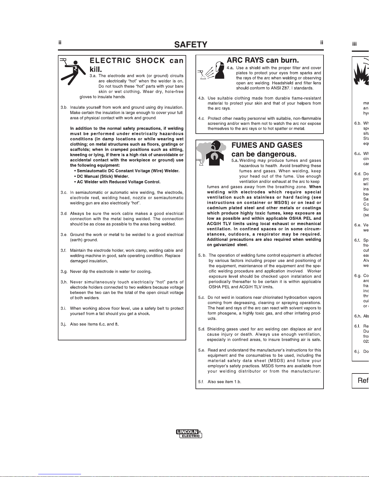
ELECTRIC AND
MAGNETIC FIELDS
maybedangerous
2.a. Electric currentflowingthrough any conductor causes
localizedElectric and Magnetic Fields (EMF). Welding
currentcreates EMF fieldsaround welding cables and
welding machines
2.b. EMF fields may interfere with some pacemakers, and
welders having a pacemaker should consult their physician
before welding.
2.c. Exposure to EMFfieldsinweldingmayhaveotherhealth
effects which are now notknown.
2.d. Allweldersshoulduse thefollowingproceduresinorderto
minimize exposure to EMFfieldsfromtheweldingcircuit:
2.d.1.
Route the electrode and workcablestogether - Secure
them with tape when possible.
2.d.2. Never coiltheelectrode lead around your body.
2.d.3. Do notplaceyourbodybetweentheelectrodeand
work cables. If theelectrodecableisonyourright
side, theworkcableshouldalsobeonyourrightside.
2.d.4. Connect theworkcabletotheworkpieceascloseas
possible to theareabeingwelded.
2.d.5. Do notworknexttoweldingpowersource.
1.h. To avoid scalding, do notremovethe
radiator pressure capwhentheengineis
hot.
For Diesel Engines: Diesel engine exhaust and
some of itsconstituentsareknowntotheState
of California to cause cancer, birth defects, and
other reproductive harm.
For Gasoline Engines: The engine exhaust from
this product contains chemicals knowntothe
StateofCaliforniatocause cancer, birth defects,
or other reproductive harm.
CALIFORNIAPROPOSITION65WARNINGS
• Sales and Service through Subsidiaries and Distributors Worldwide •
Cleveland, Ohio 44117-1199 U.S.A. TEL: 216.481.8100 FAX: 216.486.1751 WEB SITE: www.lincolnelectric.com
• World's Leader in Welding and Cutting Products •
MAGNUM® PRO 100SG SPOOL GUN
OPERATOR’S MANUAL
IMT10137
November, 2012
Copyright © Lincoln Global Inc.
Safety Depends on You
Lincoln arc welding and cutting
equipment is designed and built
with safety in mind. However,
you r ove rall s afet y can b e
increased by proper installation ...
and thoughtful operation on your
part. DO NOT INSTALL, OPER-
ATE OR REPAIR THIS EQUIPMEN T WIT HOU T RE ADIN G
THI S MA NUAL AND THE
SAFETY PRECAUTIONS CONTAINED THROUGHOUT. And,
most importantly, think before you
act and be careful.
FORENGINE
powered equipment.
1.a. Turn theengineoffbeforetroubleshootingandmaintenance
work unless themaintenanceworkrequiresittoberunning.
____________________________________________________
1.b.Operate engines in open, well-ventilated
areas or vent th
eengineexhaustfumes
outdoors.
____________________________________________________
1.c. Do not add thefueln
earanopenflamewelding arcorwhentheengineisrunning.Stop
theengineandallowittocoolbeforerefuelingtopreventspilledfuelfromvaporizingon
contact with hotenginepartsandigniting.Do
notspillfuelwhenfillingtank.Iffuelisspilled,
wipe it up anddonotstartengineuntilfumes
have been eliminated.
____________________________________________________
1.d. Keep allequip
mentsafetyguards,coversanddevicesinposition andingoodrepair.Keephands,hair,clothingandtools
away from V-belts, gears, fans and allothermovingparts
when starting, operating or repairing equipment.
____________________________________________________
1.e. In some cases it maybenece
ssarytoremovesafety
guardstoperform required maintenance. Remove
guards only when necessary andreplacethemwhenthe
maintenance requiringtheir removaliscomplete.
Always use thegreatestcarewhenworkingnearmoving
parts.
___________________________________________________
1.f. Do not putyourh
andsneartheenginefan.
Do notattempttooverridethegovernoror
idler by pushing on thethrottlecontrolrods
while theengineisrunning.
___________________________________________________
1.g. To prevent accidentally starting gasoline engines while
turning theengin
eorweldinggeneratorduringmaintenance
work, disconnect thesparkplugwires,distributorcap or
magneto wire as appropriate.
i
SAFETY
i
ARC WELDING CANBEHAZARDOUS. PROTECTYOURSELF AND OTHERS FROM POSSIBLE SERIOUS INJURY OR DEATH.
KEEP CHILDRENAWAY.PACEMAKERWEARERS SHOULD CONSULT WITH THEIR DOCTOR BEFORE OPERATING.
Read andunderstandthefollowingsafetyhighlights.Foradditional safety information, it is strongly recommended that you
purchase a copy of “Safety in Welding & Cutting - ANSI Standard Z49.1” from theAmericanWelding Society, P.O. Box 351040,
Miami, Florida33135orCSAStandardW117.2-1974.AFreecopyof“ArcWelding Safety” booklet E205isavailable from the
Lincoln Electric Company, 22801 St.ClairAvenue,Cleveland,Ohio 44117-1199.
BE SURE THAT ALL INSTALLATION, OPERATION, MAINTENANCE AND REPAIR PROCEDURESARE
PERFORMED ONLY BY QUALIFIED INDIVIDUALS.
WARNING
ELECTRIC AND
MAGNETIC FIELDS
maybedangerous
2.a. Electric currentflowingthrough any conductor causes
localizedElectric and Magnetic Fields (EMF). Welding
currentcreates EMF fieldsaround welding cables and
welding machines
2.b. EMF fields may interfere with some pacemakers, and
welders having a pacemaker should consult their physician
before welding.
2.c. Exposure to EMFfieldsinweldingmayhaveotherhealth
effects which are now notknown.
2.d. Allweldersshoulduse thefollowingproceduresinorderto
minimize exposure to EMFfieldsfromtheweldingcircuit:
2.d.1.
Route the electrode and workcablestogether - Secure
them with tape when possible.
2.d.2. Never coiltheelectrode lead around your body.
2.d.3. Do notplaceyourbodybetweentheelectrodeand
work cables. If theelectrodecableisonyourright
side, theworkcableshouldalsobeonyourrightside.
2.d.4. Connect theworkcabletotheworkpieceascloseas
possible to theareabeingwelded.
2.d.5. Do notworknexttoweldingpowersource.
1.h. To avoid scalding, do notremovethe
radiator pressure capwhentheengineis
hot.
For Diesel Engines: Diesel engine exhaust and
some of itsconstituentsareknowntotheState
of California to cause cancer, birth defects, and
other reproductive harm.
For Gasoline Engines: The engine exhaust from
this product contains chemicals knowntothe
StateofCaliforniatocause cancer, birth defects,
or other reproductive harm.
CALIFORNIAPROPOSITION65WARNINGS
vv
TThhaannkk YYoouu
for selecting a QUALITY product by Lincoln Electric. We want you
to take pride in operating this Lincoln Electric Company product •••
as much pride as we have in bringing this product to you!
Read this Operators Manual completely before attempting to use this equipment. Save this manual and keep it
handy for quick reference. Pay particular attention to the safety instructions we have provided for your protection.
The level of seriousness to be applied to each is explained below:
WARNING
This statement appears where the information must be followed exactly to avoid serious personal injury or loss of life.
This statement appears where the information must be followed to avoid minor personal injury or damage to this equipment.
CAUTION
On-Line Product Registration
- Register your machine with Lincoln Electric either via fax or over the Internet.
• For faxing: Complete the form on the back of the warranty statement included in the literature packet
accompanying this machine and fax the form per the instructions printed on it.
• For On-Line Registration: Go to our
WEB SITE at www.lincolnelectric.com. Choose “Support” and then “Register
Your Product”. Please complete the form and submit your registration.
CUSTOMER ASSISTANCE POLICY
The business of The Lincoln Electric Company is manufacturing and selling high quality welding equipment, consumables, and cutting equip-
ment. Our challenge is to meet the needs of our customers and to exceed their expectations. On occasion, purchasers may ask Lincoln Electric
for advice or information about their use of our products. We respond to our customers based on the best information in our possession at that
time. Lincoln Electric is not in a position to warrant or guarantee such advice, and assumes no liability, with respect to such information or
advice. We expressly disclaim any warranty of any kind, including any warranty of fitness for any customerʼs particular purpose, with respect
to such information or advice. As a matter of practical consideration, we also cannot assume any responsibility for updating or correcting any
such information or advice once it has been given, nor does the provision of information or advice create, expand or alter any warranty with
respect to the sale of our products.
Lincoln Electric is a responsive manufacturer, but the selection and use of specific products sold by Lincoln Electric is solely within the control
of, and remains the sole responsibility of the customer. Many variables beyond the control of Lincoln Electric affect the results obtained in
applying these types of fabrication methods and service requirements.
Subject to Change – This information is accurate to the best of our knowledge at the time of printing. Please refer to www.lincolnelectric.com
for any updated information.
Please Examine Carton and Equipment For Damage Immediately
When this equipment is shipped, title passes to the purchaser upon receipt by the carrier. Consequently, Claims
for material damaged in shipment must be made by the purchaser against the transportation company at the
time the shipment is received.
Please record your equipment identification information below for future reference. This information can be found
on your equipment nameplate.
Model Name and Sales Spec Number (K-xxx) _____________________________________
Date of Purchase __________________________________
Whenever you request replacement parts for or information on this equipment always supply the information you
have recorded above.
iv
SAFETY
iv
PRÉCAUTIONS DE SÛRETÉ
Pour votre propre protectionlireetobserver toutes lesinstructions
et les précautionsdesûretéspecifiquesquiparraissentdansce
manuelaussibienque les précautionsdesûretégénéralessuivantes:
Sûreté Pour Soudage A LʼArc
1. Protegez-vous contre la secousse électrique:
a. Lescircuits à lʼélectrode et à la piécesontsoustension
quand la machine à souder estenmarche. Eviter toujours
toutcontactentreles partiessoustensionetlapeaunue
ou lesvétements mouillés.Porter desgantssecsetsans
trouspourisolerles mains.
b. Faire trés attention de bien sʼisoler de la massequandon
soude dans desendroitshumides, ou surunplanchermetallique ou des grilles metalliques, principalement dans
lespositionsassisoucouchépourlesquellesune grande
partieducorpspeutêtreencontactaveclamasse.
c. Maintenirleporte-électrode,lapincedemasse,lecâblede
soudage et la machine à souder en bonetsûr étatdefonctionnement.
d.Nejamaisplongerleporte-électrode dans lʼeau pour le
refroidir.
e. Ne jamais touchersimultanémentlespartiessoustension
desporte-électrodesconnectés à deux machinesàsouder
parce quelatensionentrelesdeuxpincespeutêtreletotal
de la tension à vide desdeuxmachines.
f. Si on utiliselamachine à souder comme unesourcede
courantpoursoudagesemi-automatique, ces precautions
pour le porte-électrode sʼapplicuent aussi au pistolet de
soudage.
2. Dans le casdetravailaudessusduniveaudusol,seprotéger
contre leschutesdanslecasouonrecoitunchoc.Nejamais
enrouler le câble-électrodeautour de nʼimportequellepartie du
corps.
3. Un coup dʼarc peut être plus sévère quʼun coup de soliel, donc:
a. Utiliserunbon masqueavecunverrefiltrantappropriéainsi
quʼun verre blanc afindeseprotéger lesyeuxdurayonnement de lʼarc et des projectionsquandonsoudeou
quand on regarde lʼarc.
b. Porter desvêtements convenables afindeprotégerlapeau
de soudeur et desaidescontrelerayonnement de lʻarc.
c. Protéger lʼautre personnel travaillant à proximitéau
soudage à lʼaide dʼécransappropriésetnon-inflammables.
4. Desgouttesdelaitierenfusionsontémises de lʼarc de
soudage. Se protégeravecdesvêtementsdeprotectionlibres
de lʼhuile, tels que lesgantsencuir,chemiseépaisse,pantalonssansrevers,etchaussuresmontantes.
5. Toujours porter deslunettesdesécuritédanslazonede
soudage. Utiliser deslunettesavecécranslaterauxdansles
zones où lʼon pique le laitier.
6. Eloigner les matériaux inflammablesoules recouvrir afin de
prévenir tout risque dʼincendiedûaux étincelles.
7. Quandonnesoude pas, poserlapince à une endroit isolé de
la masse.Uncourt-circuit accidental peut provoquerun
échauffementetunrisque dʼincendie.
8. Sʼassurer quelamasse est connectéeleplus prés possible de
la zonedetravail quʼil est pratiquedelefaire.Sionplace la
masse surlacharpentedelaconstructionoudʼautres endroits
éloignésdelazonedetravail,onaugmentelerisquedevoir
passerlecourantdesoudage par les chainesdelevage,
câblesdegrue,ouautres circuits. Cela peut provoquer des
risques dʼincendieoudʼechauffement des chainesetdes
câbles jusquʼàcequʼilsserompent.
9. Assurer une ventilation suffisante danslazonedesoudage.
Ceci est particuliérement important pourlesoudagedetôles
galvanisées plombées,oucadmiéesoutout autre métal qui
produit des fumeés toxiques.
10.Nepas souderenprésencedevapeursdechlore provenant
dʼopérations de dégraissage, nettoyage ou pistolage. La
chaleuroules rayonsdelʼarc peuvent réagir avec les vapeurs
du solvant pour produireduphosgéne (gas fortement toxique)
ou autres produits irritants.
11. Pour obtenirdeplus amples renseignements surlasûreté, voir
le code “Code for safetyinwelding and cutting” CSA Standard
W117.2-1974.
PRÉCAUTIONSDESÛRETÉ POUR
LES MACHINESÀSOUDERÀ
TRANSFORMATEURETÀ
REDRESSEUR
1. Relier à la terrelechassisduposte conformementaucode de
lʼélectricitéetaux recommendationsdufabricant.Ledispositif
de montageoulapiece à souder doit être branché à une
bonne miseàlaterre.
2. Autant que possible, Iʼinstallationetlʼentretienduposte seront
effectués parunélectricien qualifié.
3. Avantdefaires des travaux à lʼinterieurdeposte,ladebrancher à lʼinterrupteur à la boitedefusibles.
4. Garder tous les couverclesetdispositifsdesûreté à leur place.
vv
TThhaannkk YYoouu
for selecting a QUALITY product by Lincoln Electric. We want you
to take pride in operating this Lincoln Electric Company product •••
as much pride as we have in bringing this product to you!
Read this Operators Manual completely before attempting to use this equipment. Save this manual and keep it
handy for quick reference. Pay particular attention to the safety instructions we have provided for your protection.
The level of seriousness to be applied to each is explained below:
WARNING
This statement appears where the information must be followed exactly to avoid serious personal injury or loss of life.
This statement appears where the information must be followed to avoid minor personal injury or damage to this equipment.
CAUTION
On-Line Product Registration
- Register your machine with Lincoln Electric either via fax or over the Internet.
• For faxing: Complete the form on the back of the warranty statement included in the literature packet
accompanying this machine and fax the form per the instructions printed on it.
• For On-Line Registration: Go to our
WEB SITE at www.lincolnelectric.com. Choose “Support” and then “Register
Your Product”. Please complete the form and submit your registration.
CUSTOMER ASSISTANCE POLICY
The business of The Lincoln Electric Company is manufacturing and selling high quality welding equipment, consumables, and cutting equipment. Our challenge is to meet the needs of our customers and to exceed their expectations. On occasion, purchasers may ask Lincoln Electric
for advice or information about their use of our products. We respond to our customers based on the best information in our possession at that
time. Lincoln Electric is not in a position to warrant or guarantee such advice, and assumes no liability, with respect to such information or
advice. We expressly disclaim any warranty of any kind, including any warranty of fitness for any customerʼs particular purpose, with respect
to such information or advice. As a matter of practical consideration, we also cannot assume any responsibility for updating or correcting any
such information or advice once it has been given, nor does the provision of information or advice create, expand or alter any warranty with
respect to the sale of our products.
Lincoln Electric is a responsive manufacturer, but the selection and use of specific products sold by Lincoln Electric is solely within the control
of, and remains the sole responsibility of the customer. Many variables beyond the control of Lincoln Electric affect the results obtained in
applying these types of fabrication methods and service requirements.
Subject to Change – This information is accurate to the best of our knowledge at the time of printing. Please refer to www.lincolnelectric.com
for any updated information.
Please Examine Carton and Equipment For Damage Immediately
When this equipment is shipped, title passes to the purchaser upon receipt by the carrier. Consequently, Claims
for material damaged in shipment must be made by the purchaser against the transportation company at the
time the shipment is received.
Please record your equipment identification information below for future reference. This information can be found
on your equipment nameplate.
Model Name and Sales Spec Number (K-xxx) _____________________________________
Date of Purchase __________________________________
Whenever you request replacement parts for or information on this equipment always supply the information you
have recorded above.
iv

TABLE OF CONTENTS
Page
Installation Section--------------------------------------------------------------------------------A
Technical Specification---------------------------------------------------------------------------A-1
Unpacking the Spool Gun-----------------------------------------------------------------------A-1
Safety Precautions--------------------------------------------------------------------------------A-2
Locating Spool Gun Components And Features------------------------------------------A-2
Assembly of Items Inside the Magnum Pro Spool Gun
---------------------------------------A-3
Welding Machines--------------------------------------------------------------------------------A-4
Recommended Welding Machines-----------------------------------------------------------A-5
Spool Gun / Wire Drive Selector Switch Installation--------------------------A-6 thru A-9
Routine Welding Machine Preparation------------------------------------------------------A-10
Preparing the Spool Gun-----------------------------------------------------------------------A-10
Loading Aluminum-----------------------------------------------------------------A-10 thru A-13
Connecting the Gun to the Welding Machine--------------------------------------------A-13
__________________________________________________________________
O
PERATION Section----------------------------------------------------------------------------------B
Safety Precaution---------------------------------------------------------------------------------B-1
Product Description-------------------------------------------------------------------------------B-1
Machine Speed and Voltage tap Settings--------------------------------------------B-1, B-2
Welding Procedures------------------------------------------------------------------------------B-3
__________________________________________________________________
Maintenance Section------------------------------------------------------------------------------ D
Safety Precautions--------------------------------------------------------------------------------D-1
Routine and Periodic Maintenance-----------------------------------------------------------D-1
Recommended Tools-----------------------------------------------------------------------------D-1
Cleaning and Inspections-----------------------------------------------------------------------D-1
P6 Connector Pin-Out----------------------------------------------------------------------------D-1
Gas Diffuser Replacement----------------------------------------------------------------------D-1
Liner Assembly Replacement or Cleaning--------------------------------------------------D-2
Drive Roll Replacement--------------------------------------------------------------------------D-2
Idle Roll Assembly Replacement--------------------------------------------------------------D-3
Gun Tube Assembly Replacement------------------------------------------------------------D-3
Wire Drive Assembly Removal And Installation--------------------------------------------D-4
Trigger Assembly Replacement----------------------------------------------------------------D-4
Welding Cable Assembly Replacement-----------------------------------------------D-4, D-5
Correcting Wire Shaving issues--------------------------------------------------------------D-5
__________________________________________________________________
Troubleshooting Section -------------------------------------------------------------------------E
Safety Precautions--------------------------------------------------------------------------------E-1
How To Use Trouble Shooting Guide---------------------------------------------------------E-1
Troubleshooting----------------------------------------------------------------------------E-2 to E-4
____________________________________________________________________
Diagrams Section -----------------------------------------------------------------------------------F
Wiring Diagrams------------------------------------------------------------------------------------F-1
____________________________________________________________________
Parts List--------------------------------------------------------------------------------P-554 Series
____________________________________________________________________

TABLE OF CONTENTS
Page
Troubleshooting Section -------------------------------------------------------------------------E
Safety Precautions--------------------------------------------------------------------------------E-1
How To Use Trouble Shooting Guide---------------------------------------------------------E-1
Troubleshooting----------------------------------------------------------------------------E-2 to E-4
____________________________________________________________________
Diagrams Section -----------------------------------------------------------------------------------F
Wiring Diagrams------------------------------------------------------------------------------------F-1
____________________________________________________________________
Parts List--------------------------------------------------------------------------------P-554 Series
____________________________________________________________________

%&&!
& %"&! % 'G"$!%%"!!'
!
) "$!%%
)$!+%
)$%,%&$%
%"!!%,
$&) '$$ &
'&++
!($)&
&
!($%,!' !*
&!!'
&!!!!
K3269-1 MAGNUM®PRO100SG Spool Gun
Aluminum GMAW (MIG), DC electrode positive
polarity with 100% argon welding shielding gas.
Aluminum only: alloys 4043 or 5356
Solid wire 0.030 or 0.035 inches (0.8 or 0.9 mm)
1 lb. weight, nominal 4 inch diameter spool
130 amps at 30% for 10-minute basis
3.5 lbs. with cable but without case or spool
10.0±0.2 feet
In inches: 15.75 long x 10.50 high x 4.25 thick max.,
without case or gun cable.
Semiautomatic (manually-guided)
Air-cooled
' " &%"!!'
The spool gun is factory-assembled and tested, and then packed in its own cushioned carrying case. It is shipped fully-equipped to weld with 0.035 inch diameter aluminum wire. After opening the case, check that it contains the following items:
1. One fully assembled K3269-1 spool gun.
2. One T11862-65 Conical Compression Spring for use with alloy 5356 wire (spool
not included).
3. One spool of 0.035 aluminum alloy 4043 wire
4. Three S28172-1 contact tips
5. One instruction manual (IMT10137)
6. One M21182 electrical harness with toggle switch.
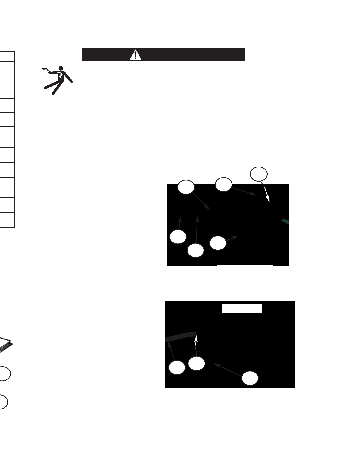
!& %"!!' !"! &% &'$%
(See Figure 1.A for Items 1 thru 6)
1. Gas Nozzle and Contact Tip.
2. Straightened Gun Tube Assembly.
3. 1/4-Turn Locking Collar.
4. Trigger Assembly.
5. Spool Cover: Provides easy, wide-
open access to spool and wire
drive.
6. Locking Knob: Captive in spool
cover.
(See Figure A.2 for these following items)
7. Integrated Single-Piece Cable:
The Magnum
neat and clean appearance; sim-
plifies cable managem ent and
reduces entanglements.
8. Standard Durable Strain Relief
Clamp.
9. Three Captive Hex Nuts.
M
A
G
N
U
M
P
R
O
1
0
0
S
G
®
&$J%!
F&@=9?4159;@?;:B1=!-??41B170593;:B1=>:@=/1.12:=1
59>?-77-?5:9:=/4-935930=5A1=:77>-90:=3@501>
F:9:??:@/4171/?=5/-77D75A1;-=?>
F)41959/4593B5?4?413@9?=5331=171/?=:01-900=5A181/4-95>8
-=14:??:B:=6-903=:@90-90/:@70=18-59191=35E10>1A1=-7
>1/:90>-2?1=?413@9?=5331=5>=171->10
-----------------------------------------------------------------------------------------------------
Plastic Bag
!& %"!!' !"! &% &'$%
(See Figure 1.A for Items 1 thru 6)
1. Gas Nozzle and Contact Tip.
2. Straightened Gun Tube Assembly.
3. 1/4-Turn Locking Collar.
4. Trigger Assembly.
5. Spool Cover: Provides easy, wideopen access to spool and wire
drive.
6. Locking Knob: Captive in spool
cover.
(See Figure A.2 for these following items)
7. Integrated Single-Piece Cable:
The Magnum
®
Pro design provides
neat and clean appearance; simplifies cable managem ent and
reduces entanglements.
8. Standard Durable Strain Relief
Clamp.
9. Three Captive Hex Nuts.
M
A
G
N
U
M
P
R
O
1
0
0
S
G
®
'$
Left Side View
'$
Right Side View
%&&!
%&+"$'&! %
&$J%!
F&@=9?4159;@?;:B1=!-??41B170593;:B1=>:@=/1.12:=1
59>?-77-?5:9:=/4-935930=5A1=:77>-90:=3@501>
F:9:??:@/4171/?=5/-77D75A1;-=?>
F)41959/4593B5?4?413@9?=5331=171/?=:01-900=5A181/4-95>8
-=14:??:B:=6-903=:@90-90/:@70=18-59191=35E10>1A1=-7
>1/:90>-2?1=?413@9?=5331=5>=171->10
-----------------------------------------------------------------------------------------------------
)$
%&&!
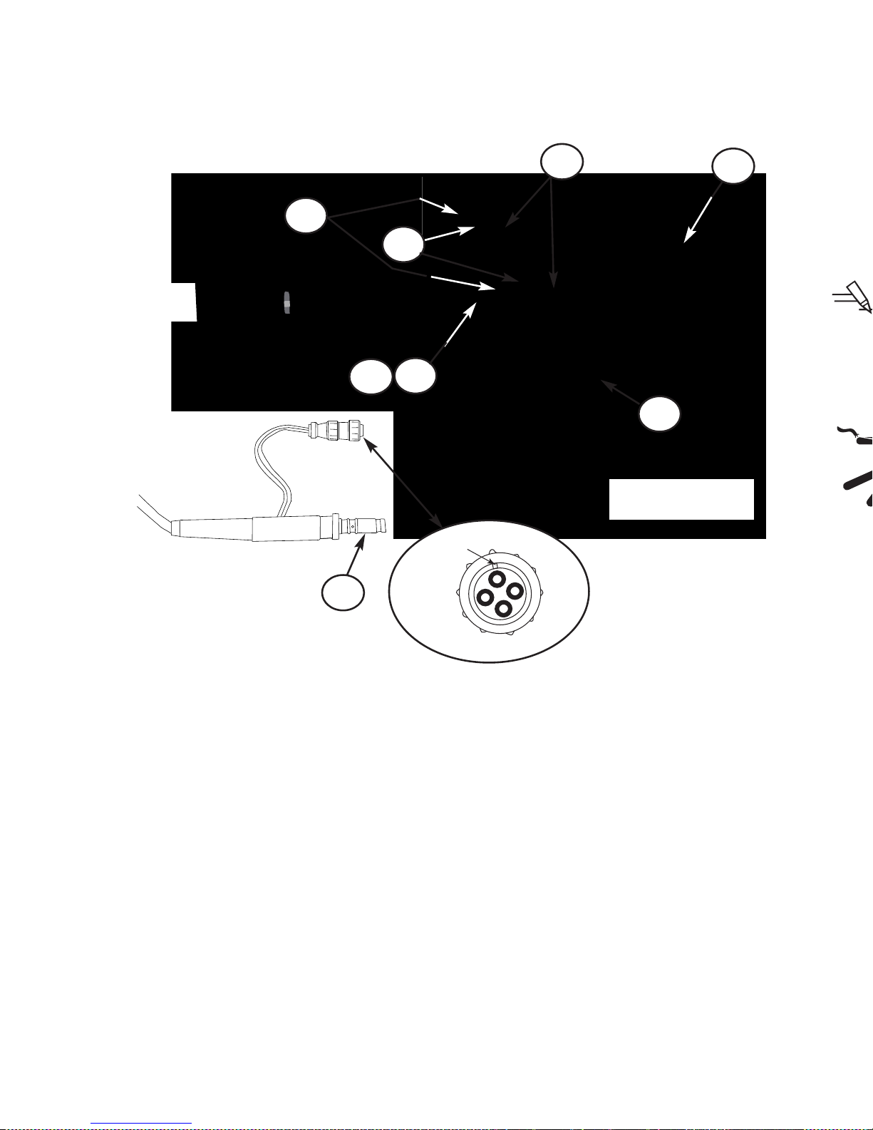
%%+!&% %& 'G"$!%"!!'
'$
) %
-----------------------------------------------------------------------------------------------------
%"!!'
&$J%!
F1?-7 ;-=?> =18-59 -? B170593 A:7?-31 2:= >1A1=-7 >1/:90> -2?1= ?=5331= 5>
=171->10$1-0B-=95937-.17:93@9
F&45>;=:0@/?>4-779:?.1@>1059;=1/5;5?-?5:9:=59B1?:=0-8;7:/-?5:9>
------------------------------------------------------------------------------------------------------
&!"()
Spool Cover and left
handle removed
Machine Connections
11
22
44
33
P6 CONNECTOR PINOUT
MASTER KEY
1. Liner Assembly feeds all specified
wire.
2. Drive Roll: This Drive Roll feeds all
specified wires.
3. Idle Roll Assembly: Non-adjustable
tension setting for all specified wires
4. Incoming Wire Guide: Highly wearresistant.
5. P6 Connector Control Leads: Motor
Pow er and Trigg er. (S ee
Mai nten ance Sec tion f or m ore
details)
6. Welding Power and Shielding Gas
Machine connection (Sealed with 2
o-rings).
7. Locking Knob: Independently retains
the wire spool on the spindle.
8. Liner Assembly: Includes a gas seal
with the cable connector and is the
outgoing wire guide.
9. Only 4 sub-assemblies: gun tube;
cable; wire drive; trigger.
10. Conical spring (not shown) serves
as the spool brake (use only with
aluminum alloy 5356).
%&&!
%&+"$'&! %
) %
F$1-0-90@901=>?-90?41B1705938-/4591K>59>?=@/?5:98-9@
-7-90-774-E-=0B-=9593>:91<@5;819?-9059?418-9@-7
F)1-= ?41 ;=:;1= ;1=>:9-7 ;=:?1/?5A1 1<@5;819? 2:= B170593
59/7@0593.@?9:?7585?10?:>-21?D37->>1>41-=593;=:?1/?5:9
B17059341781?B17059337:A1>-90B17059371-?41=>
-----------------------------------------------------------------------------------------------------
%"!!'
&$J%!
F&41>;::7:2B5=18-D2-77:@?:2?413@952?417:/659369:.5>
9:?59>?-7710
F1?-7;-=?>8-D.1-?B170593A:7?-31171/?=5/-77D4:?
F1?-7 ;-=?> =18-59 -? B170593 A:7?-31 2:= >1A1=-7 >1/:90> -2?1= ?=5331= 5>
=171->10$1-0B-=95937-.17:93@9
F&45>;=:0@/?>4-779:?.1@>1059;=1/5;5?-?5:9:=59B1?:=0-8;7:/-?5:9>
------------------------------------------------------------------------------------------------------
'&!
)$

%&&!
!& 9>?-77-?5:9 :2 ?41 4-=91>> -90 >;::7 3@9 >171/?:= >B5?/4 5>
9:? =1<@5=10 2:= -77 8-/4591> 2 - >;::7 3@9 >B5?/4 5> ;=159>?-7710 59 ?41
8-/4591K> B5=1 0=5A1 /:8;-=?819? ?419 ?41 %"!! ' )$ $(
%&!$%)& %&&! %&! /-9.105>=13-=010
%"!!' )$$(
%&!$%)&
%&&!
1
. Install the M21182 electrical adapter
harness that came with the spool gun
per the following instructions.
&$J%!
5>/ :991 /? 59; @ ?
------------------------------------------------
!" &
3. Remove two 5/16“ hex hinge screws
from door.
4. Remove ten 5/16“ hex screws from
cover.
RECOMMENDED WELDING MACHINES
MACHINE NAME
K-NUMBER
CODE NUMBER
INSTALLATION OF M21182 HARNESS
AND SELECTOR SWITCH
POWER MIG 216
POWER MIG 180C
POWER MIG 140C
POWER MIG 180 DUAL
POWER MIG 180C (AU)
POWER MIG 180C (CE)
PRO CORE 125T WELDER
PRO MIG 140T WELDER
WELD PAK 125HD WELDER
WELD PAK 140HD WELDER
MIG PAK 140 WELDER
EASY CORE 125 WELDER
EASY MIG 140 WELDER
CORE PAK 125 WELDER
PRO MIG 180T WELDER
WELD PACK 180HD WELDER
MIG PAK 180 WELDER
SP-140T
SP-180T
EASY MIG 180 WELDER
K2816-2
K2473-2
K2471-2
K3018-2
K2668-1
K2661-1
K2479-1
K2480-1
K2513-1
K2514-1
K2658-1
K2696-1
K2697-1
K2785-1
K2481-1
K2515-1
K2659-1
K2688-2
K2689-2
K2698-1
11817
11820
11804
11828
11444
11442
11631
11634
11632
11635
11636
11633
11637
11639
11646
11647
11648
11805
11822
11650
NOT REQUIRED
REQUIRED
REQUIRED
NOT REQUIRED
REQUIRED
REQUIRED
SPOOL GUN USE NOT AVAILABLE
NOT REQUIRED
SPOOL GUN USE NOT AVAILABLE
NOT REQUIRED
NOT REQUIRED
SPOOL GUN USE NOT AVAILABLE
NOT REQUIRED
SPOOL GUN USE NOT AVAILABLE
REQUIRED
REQUIRED
REQUIRED
REQUIRED
REQUIRED
REQUIRED

!& 9>?-77-?5:9 :2 ?41 4-=91>> -90 >;::7 3@9 >171/?:= >B5?/4 5>
9:? =1<@5=10 2:= -77 8-/4591> 2 - >;::7 3@9 >B5?/4 5> ;=159>?-7710 59 ?41
8-/4591K> B5=1 0=5A1 /:8;-=?819? ?419 ?41 %"!! ' )$ $(
%&!$%)& %&&! %&! /-9.105>=13-=010
%&&!
%"!!' )$$(
%&!$%)&
%&&!
1
. Install the M21182 electrical adapter
harness that came with the spool gun
per the following instructions.
&$J%!
5>/ :991 /? 59; @ ?
;:B 1 = 2=:8 ?4 1
8-/4591
------------------------------------------------
!" &
3. Remove two 5/16“ hex hinge screws
from door.
4. Remove ten 5/16“ hex screws from
cover.
5. Remove screws from cover.
( is the location of two 3/4” long
screws.
6. Remove cover.
7. If machine has a plastic handle ,
then remove screw .
)$
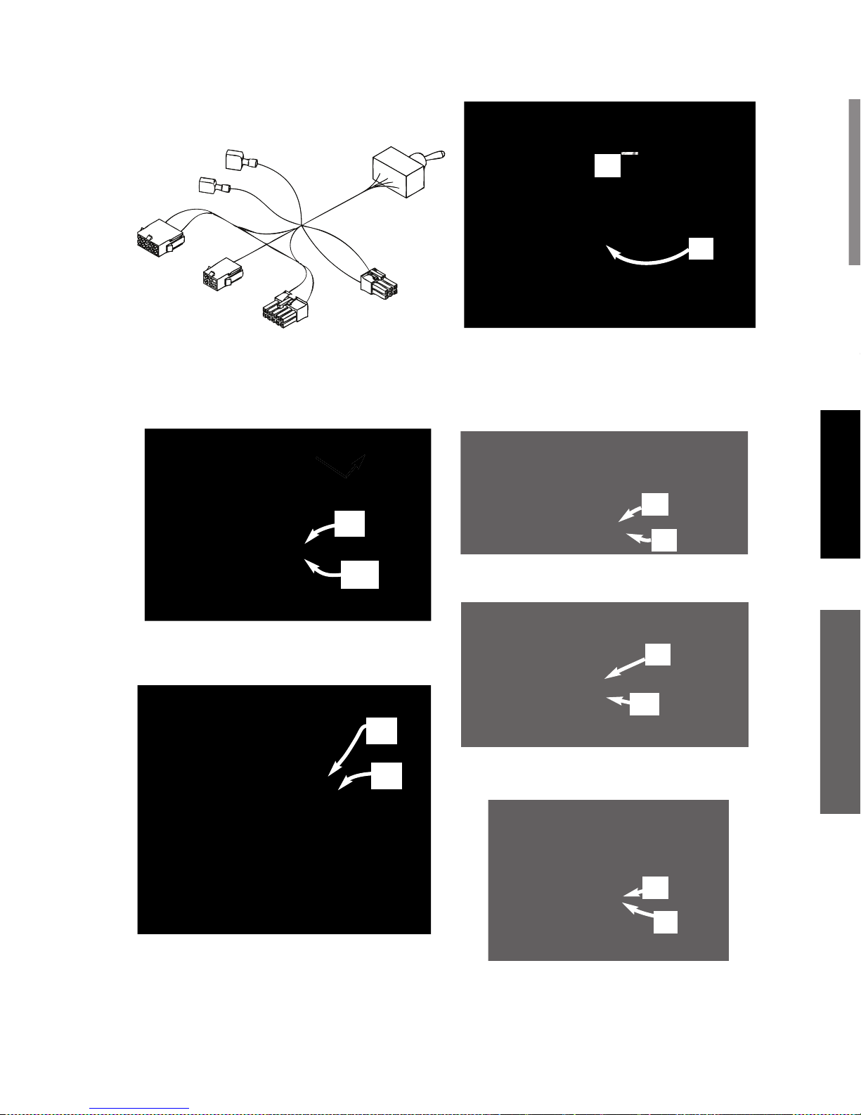
11.D. Find assembled pair of machine
terminals (leads 543A & 544A)
and disconnect. Go to step 13.
!%(!"&! %"!&
&$
?4=@
$18:A1";59 from spot
timer harness J9 (6-pin).
:991/?" ;59to adapter
harness J8 (6-pin).
%&&!
&$! &! %
8. Adapter harness. All 6 connections
shown are used, and each one is
unique.
(Proceed as follows)
9. A. $18:A1";59 from board
J3 (10-pin).
9.B. :991/?";59 to har-
ness J7 (10-pin).
:991/?4-=91>>";59 to
board J3 (10-pin).
!% !&(!"&!
%"!&&$
?4=@
$18:A1";59 from
board J5 (6-pin).
:991/?";59 to har-
ness J8 (6-pin).
:991/?4-=91>>";59
to board J5 (6-pin).
Toggle Switch
P8 (6-pin)
P7 (10-pin)
J8 (6-pin)
543A
(Female)
544A
(Male)
"
"
"
"
"
"

%&&!
11.D. Find assembled pair of machine
terminals (leads 543A & 544A)
and disconnect. Go to step 13.
!%(!"&! %"!&
&$
?4=@
$18:A1";59 from spot
timer harness J9 (6-pin).
:991/?" ;59to adapter
harness J8 (6-pin).
:991/?-0-;?1=4-=91>>"
;59 to spot timer harness J9 (6-
pin).
12.D. Find assembled pair of machine
terminals (leads 543A & 544A)
and disconnect.
13. Connect terminals:
connect machine male (lead
543A) to adapter harness female
(lead 543A).
connect machine female (lead
544A) to adapter harness male
(lead 544A).
9>@=1?4-??417:/6593?-.>:9-77
/:991/?:=>-=17-?/410/7:>10
"
"
"

MAGNUM PRO 100SG
K3269-1
K3269-1
®
ROUTINE WELDING MACHINE PREPARATION
------------------------------------------------------------------------
2. Machine polarity setting: Set to DC electrode positive
polarity per the machine’s Instruction Manual.
3. Gas selection and flow rate: Connect 100% welding
grade argon gas supply to the machine’s gas solenoid
valve. Set the supply regulator to deliver a gas flow rate
of 20 to 50 SCFH thru the spool gun.]
4. Flip the machine’s wire drive selector switch (behind the
access door) to "MAGNUM
A.4)
PREPARING THE SPOOL GUN
------------------------------------------------------------------------
2. The Conical Spring is used as the spool brake only when
feeding the stronger and harder aluminum alloy 5356.
The Conical Spring must be removed from the spool gun
whenever using the softer aluminum alloy 4043.
INSTALLATION
A-9 A-10
MOUNTING THE SWITCH
15. Remove the plug button from the
panel hole.
16. Plug button is no longer needed.
Discard.
17. Remove mounting nut from switch.
Keep mounting nut for installation.
18. Install switch into panel hole.
Ensure washer tab is fully seated
into smaller hole.
19. Reinstall mounting nut onto switch.
Wrench tighten.
RE-ASSEMBLE MACHINE AS
FOLLOWS:
20. Reinstall screw into plastic handle (if
so equipped).
21. Reinstall cover.
22. Reinstall door.
23. Reconnect input power to the
machine.

INSTALLATION
MAGNUM PRO 100SG
K3269-1
K3269-1
®
ROUTINE WELDING MACHINE PREPARATION
ELECTRIC SHOCK CAN KILL.
1. Disconnect input power to the machine.
------------------------------------------------------------------------
2. Machine polarity setting: Set to DC electrode positive
polarity per the machine’s Instruction Manual.
3. Gas selection and flow rate: Connect 100% welding
grade argon gas supply to the machine’s gas solenoid
valve. Set the supply regulator to deliver a gas flow rate
of 20 to 50 SCFH thru the spool gun.]
4. Flip the machine’s wire drive selector switch (behind the
access door) to "MAGNUM
®
PRO100SG". (See Figure
A.4)
FIGURE A.4
WARNING
PREPARING THE SPOOL GUN
ELECTRIC SHOCK CAN KILL.
1. Disconnect input power to the machine.
------------------------------------------------------------------------
2. The Conical Spring is used as the spool brake only when
feeding the stronger and harder aluminum alloy 5356.
The Conical Spring must be removed from the spool gun
whenever using the softer aluminum alloy 4043.
WARNING

7. Guide straightened wire through inlet
wire guide and toward drive roll
groove.
FIGURE A.11
8. While holding open the idle roll, slide
end of wir e th roug h dr ive rol l’s
groove and toward gun tube liner.
FIGURE A.12
9. Slide the wire into the liner until it
extends approximately 1 inch beyond
the end of the gas diffuser. Release
idle roll tab without snapping it.
FIGURE A.13
INSTALLATION
A-11 A-12
LOADING ALUMINUM WIRE
1. Remove gas nozzle and contact tip.
Remove spool cover by unscrewing
captive locking knob.
FIGURE A.5
2. Remove locking knob from spindle
bolt by unscrewing it.
FIGURE A.6
3. Select wire alloy and diameter needed. Alloy 4043 and 0.035 wire size
shown. Remove packaging and data
sheet from wire spool.
FIGURE A.7
4. Extend approximately 12 inches
of wire from spool. Straighten it
out by back-bending it. Use care
to prevent the wire from dereeling.
FIGURE A.8
5. Cut off bent e n d of wi re, le aving
straight section.
FIGURE A.9
6. Gen tly p ull o pen t he id le ro ll
assembly to expose the drive roll
groove.
FIGURE A.10
M
A
G
N
U
M
P
R
O
1
0
0
S
G
®
A
M
A
A
®
®
P
R
N
N
N
U
M
P
R
R
®
O
O
1
1
1
0
0
0
0
S
0
S
G
Alloy
Size

INSTALLATION
7. Guide straightened wire through inlet
wire guide and toward drive roll
groove.
FIGURE A.11
8. While holding open the idle roll, slide
end of wir e th roug h dr ive rol l’s
groove and toward gun tube liner.
FIGURE A.12
9. Slide the wire into the liner until it
extends approximately 1 inch beyond
the end of the gas diffuser. Release
idle roll tab without snapping it.
FIGURE A.13
10a. Alloy 4043: Roll up remaining wire
back onto spool and place spool
onto gun spindle. Install locking
knob and finger-tighten. Go to step
11.
FIGURE A.14
10b. Alloy 5356: Install Conical Spring,
small end first, onto gun spindle
(A). Roll up remaining wire back
onto spool and place spool onto
gun spindle. Install locking knob
and finger-tighten.
FIGURE A.15
11. Grasp the free end of the wire at the
gas diffuser and slowly pull approximat ely 12 to 24 in ches of wi re
through the spool gun. There should
only be 1 to 2 lbs. of resistance. If
force is greater than 2 lbs. wire is
bin ding in th e g un (al s o s ee
Troubleshooting guide).
FIGURE A.16
A

A-13
INSTALLATION NOTES
12. Cut off excess wire 1 to 2 inches
from gas diffuser. Install properlysized contact tip slightly past handtight. Install gas nozzle and handtighten.
FIGURE A.17
13. Rei nsta ll s pool c ove r. 1 : tu ck
cover’s tab in place at arrow and
hold with thumb. 2: swing cover
closed. 3: finger-tighten lo c king
knob. 4: check for uniform fit all
around cover.
FIGURE A.18
CONNECTING THE GUN TO THE
WELDING MACHINE
1. Disconnect input power to the
machine.
2. Make sure that the gun locking knob
is loosened. (See Figure 20).
3. Fully insert gun cable connection
(welding power and gas supply) into
machine. Note that the master Key
way for P6 connector is located at
the arrow.
FIGURE A.19
4. Check that the cable connector’s
end is flush with insulator at A.
Tighten gun locking knob (B) onto
cable connector.
FIGURE A.20
M
A
G
N
U
M
P
R
O
1
0
0
S
G
®
M
N
A
A
N
M
M
M
M
R
ROR
1
0
®
R
P
O
1
R
0
0
0
0
S
G
1
2
3
4
P6
Connector
Key way
B
A

MAGNUM PRO 100SG
!"$&!
%&+"$'&! %
Read and understand this entire section before
operating the machine.
&$%!/-96577
F:9:??:@/4171/?=5/-77D75A1;-=?>
:=171/?=:01B5?4>659:=B1?
/7:?4593
F 9>@7-?1D:@=>1722=:8B:=6-903=:@90
F 7B-D>B1-=0=D59>@7-?59337:A1>
F$1-0-902:77:BH71/?=5/ %4:/6)-=9593>I
59?41%-21?D>1/?5:952B1705938@>?.1;1=
2:=810 @901= 171/?=5/-77D 4-E-=0:@> /:905
?5:9>>@/4->B17059359B1?-=1->:=:9:=
59?41B:=6;51/1
'% %%
/-9.10-931=:@>
F11;D:@=41-0:@?:22@81>
F'>1 A19?57-?5:9 := 1C4-@>? ?: =18:A1 2@81>
2=:8.=1-?4593E:91
) %"$%
/-9/-@>125=1:=
1C;7:>5:9
F 11;27-88-.718-?1=5-7-B-D
F : 9:? B170 :9 /:9?-591=> ?4-? 4-A1 4170
/:8.@>?5.71>
$$+%
/-9.@=9
F )1-=1D11-=-90.:0D;=:?1/?5:9
!.>1=A1 -005?5:9-7 %-21?D @5017591>
01?-571059?41.13599593:2?45>8-9@-7
------------------------------------------------------------
"$!'&%$"&!
• Reliable, low-price aluminum welding accessory
for novice and experienced welders.
• Completely enclosed system.
• All combinations of specified aluminum alloys
and wire diameters can be fed with the same
drive roll and liner assembly.
• Gun cable compactly integrates welding current
and gas supplies with gun control functions.
• Uses reliable gun and feeder hardware from
Lincoln’s Magnum® 100L Gun, Innershield
guns, and small Power Mig products.
%" (!&
&"%&& %
)$
Alloy:
Wire Size:
Weldment
Thickness
22 ga
20 ga
18 ga
16 ga
14 ga
12 ga
10 ga
3/16 in.
Speed
2
2.5
3.5
3.5
4.5
4.5
5
6.5
Voltage
Tap
A
A
A
B
D
E
E
E
Speed
1.5
1.5
2
3
3.5
3.5
4
5
Voltage
Tap
A
A
A
B
D
D
E
E
0.030
0.035
4043
POWER MIG 180T MACHINE
Alloy:
Wire Size:
Weldment
Thickness
22 ga
20 ga
18 ga
16 ga
14 ga
12 ga
10 ga
3/16 in.
Speed
2
2
3
4
4.5
4
5
5
Voltage
Tap
D
D
E
F
G
I
J
MAX
Speed
1.5
1.5
3
3.5
4
3.5
4
5
Voltage
Tap
D
D
E
F.5
H
J
J
MAX
0.030
0.035
4043
POWER MIG 180C MACHINE
Alloy:
Wire Size:
Weldment
Thickness
22 ga
20 ga
18 ga
16 ga
14 ga
12 ga
10 ga
3/16 in.
Speed
3
3
4
5
5.5
7.5
8
8
Voltage
Tap
A
A
B
B
D
E
E
E
Speed
2
2
3
4
5
6
6.5
6.5
Voltage
Tap
A
A
B
B
C
E
E
E
0.030
0.035
5356
POWER MIG 180T MACHINE
Alloy:
Wire Size:
Weldment
Thickness
22 ga
20 ga
18 ga
16 ga
14 ga
12 ga
10 ga
3/16 in.
Speed
3
3
5
5
6
6
N/A
N/A
Voltage
Tap
A
A
B
D
D
E
N/A
N/A
Speed
2.5
2.5
4
4.5
5
5
N/A
N/A
Voltage
Tap
A
A
B
D
D
E
N/A
N/A
0.030
0.035
5356
POWER MIG 140T MACHINE
Alloy:
Wire Size:
Weldment
Thickness
22 ga
20 ga
18 ga
16 ga
14 ga
12 ga
10 ga
3/16 in.
Speed
3
3
5
6
6.5
7
N/A
N/A
Voltage
Tap
E
E
F
G
I
MAX
N/A
N/A
Speed
2.5
2.5
4.5
5.5
5
5.5
N/A
N/A
Voltage
Tap
E
E
F
G
J
MAX
N/A
N/A
0.030
0.035
4043
POWER MIG 140C MACHINE
Alloy:
Wire Size:
Weldment
Thickness
22 ga
20 ga
18 ga
16 ga
14 ga
12 ga
10 ga
3/16 in.
Speed
2
2
3
4
3
5
N/A
N/A
Voltage
Tap
E
E
E.5
G
I
MAX
N/A
N/A
Speed
1.5
1.5
3
3
3
4
N/A
N/A
Voltage
Tap
E
E
F
G
J
MAX
N/A
N/A
0.030
0.035
5356
POWER MIG 140C MACHINE
Alloy:
Wire Size:
Weldment
Thickness
22 ga
20 ga
18 ga
16 ga
14 ga
12 ga
10 ga
3/16 in.
Speed
2.5
2.5
3
3
3.5
3.5
N/A
N/A
Voltage
Tap
B
B
C
D
E
E
N/A
N/A
Speed
2
2
2
2.5
3
3.5
N/A
N/A
Voltage
Tap
B
B
C
D
E
E
N/A
N/A
0.030
0.035
4043
Weld-Pak 125 MACHINE
Alloy:
Wire Size:
Weldment
Thickness
22 ga
20 ga
18 ga
16 ga
14 ga
12 ga
10 ga
3/16 in.
Speed
2
2.5
3.5
4
4
4.5
N/A
N/A
Voltage
Tap
A
A
B
D
E
E
N/A
N/A
Speed
1.5
2
2.5
3
3
3
N/A
N/A
Voltage
Tap
A
B
C
D
E
E
N/A
N/A
0.030
0.035
4043
POWER MIG 140T MACHINE
Alloy:
Wire Size:
Weldment
Thickness
22 ga
20 ga
18 ga
16 ga
14 ga
12 ga
10 ga
3/16 in.
Speed
3
3.5
5
6
7
8
8
9
Voltage
Tap
C
D
E
F
G
H
I
MAX
Speed
2.5
3
3.5
4.5
5.5
6
6
7
Voltage
Tap
C
D
E
F
G
H
I
MAX
0.030
0.035
5356
POWER MIG 180C MACHINE

!"$&!
Alloy:
Wire Size:
Weldment
Thickness
22 ga
20 ga
18 ga
16 ga
14 ga
12 ga
10 ga
3/16 in.
Speed
3
3
5
5
6
6
N/A
N/A
Voltage
Tap
A
A
B
D
D
E
N/A
N/A
Speed
2.5
2.5
4
4.5
5
5
N/A
N/A
Voltage
Tap
A
A
B
D
D
E
N/A
N/A
0.030
0.035
5356
POWER MIG 140T MACHINE
Alloy:
Wire Size:
Weldment
Thickness
22 ga
20 ga
18 ga
16 ga
14 ga
12 ga
10 ga
3/16 in.
Speed
3
3
5
6
6.5
7
N/A
N/A
Voltage
Tap
E
E
F
G
I
MAX
N/A
N/A
Speed
2.5
2.5
4.5
5.5
5
5.5
N/A
N/A
Voltage
Tap
E
E
F
G
J
MAX
N/A
N/A
0.030
0.035
4043
POWER MIG 140C MACHINE
Alloy:
Wire Size:
Weldment
Thickness
22 ga
20 ga
18 ga
16 ga
14 ga
12 ga
10 ga
3/16 in.
Speed
2
2
3
4
3
5
N/A
N/A
Voltage
Tap
E
E
E.5
G
I
MAX
N/A
N/A
Speed
1.5
1.5
3
3
3
4
N/A
N/A
Voltage
Tap
E
E
F
G
J
MAX
N/A
N/A
0.030
0.035
5356
POWER MIG 140C MACHINE
Alloy:
Wire Size:
Weldment
Thickness
22 ga
20 ga
18 ga
16 ga
14 ga
12 ga
10 ga
3/16 in.
Speed
2.5
2.5
3
3
3.5
3.5
N/A
N/A
Voltage
Tap
B
B
C
D
E
E
N/A
N/A
Speed
2
2
2
2.5
3
3.5
N/A
N/A
Voltage
Tap
B
B
C
D
E
E
N/A
N/A
0.030
0.035
4043
Weld-Pak 125 MACHINE
Alloy:
Wire Size:
Weldment
Thickness
22 ga
20 ga
18 ga
16 ga
14 ga
12 ga
10 ga
3/16 in.
Speed
2
2.5
3.5
4
4
4.5
N/A
N/A
Voltage
Tap
A
A
B
D
E
E
N/A
N/A
Speed
1.5
2
2.5
3
3
3
N/A
N/A
Voltage
Tap
A
B
C
D
E
E
N/A
N/A
0.030
0.035
4043
POWER MIG 140T MACHINE
Alloy:
Wire Size:
Weldment
Thickness
22 ga
20 ga
18 ga
16 ga
14 ga
12 ga
10 ga
3/16 in.
Speed
3
3.5
5
6
7
8
8
9
Voltage
Tap
C
D
E
F
G
H
I
MAX
Speed
2.5
3
3.5
4.5
5.5
6
6
7
Voltage
Tap
C
D
E
F
G
H
I
MAX
0.030
0.035
5356
POWER MIG 180C MACHINE
OPERATION
B-3
After choosing the proper welding wire
for your application, load the aluminum
wire, connect the gun and cable to the
welding machine. (See Ins ta llation
Section).
WELDING PROCEDURES
1. Read and understand Arc Welding Safety
Precautions located throughout this manual
and the Welding Machine’s Instruction Manual.
Also for helpful hints in welding see (LTW1) the
Learn to Weld manual which is supplied with
the welding machine.
2. Obtain and use the proper personal protective
equipment for welding. Connect the WORK
(welding ground) cable(-) to piece(s) being
welded. Make sure gas hose from cylinder’s
regulator is connected to welder’s gas INLET.
Open cylinder’s gas valve.
3. Connect input power to the machine.
4. Turn the machine’s power switch to "on". Set
wire speed and voltage tap settings to tables
which are provided in the beginning of this
section.
5. Flip toggle selector switch inside of machine to
"MAGNUM
®
Pro 100SG" position. Press and
hold trigger for about 5 seconds to purge hose.
Be sure the Gas flow rate is set to 20 to 50
SCFH thru the spool gun.
SAFETY PRECAUTIONS
ELECTRIC SHOCK can kill.
• Only qualified personnel
should perform this main-
tenance.
• Turn the input power OFF at the dis-
connect switch or fuse box before
working on this equipment.
• Do not touch electrically hot parts.
-----------------------------------------------------
ROUTINE AND PERIODIC
MAINTENANCE
RECOMMENDED TOOLS
• #2 Phillips screw-driver
• Slotted screw-driver
• 5/16 inch nut driver
• Torque Wrench
• Adjustable-jaw pliers
• 7/16 inch open-end wrench (gas diffuser)
• 9/16 inch open-end wrench (gun tube nut)
• Welding pliers (optional)
• Wire cutter
• Wire stripper
• Needle nose pliers
• Terminal crimping tool
• Flashlight
• Hand-held electrical meter *
• 3.0 mm metric allen wrench (drive roll
screw)
• Tape measure or 6-inch scale
• Tachometer (optional)
*Note: Two mete rs are used fo r s imultaneou sly
measuring drive motor’s voltage and current.
CLEANING AND INSPECTIONS
• Vacuum out any aluminum shavings that may
have accumulated inside of the gun. ( See
Correcting Wire Shaving Issues in this section).
• Wipe off dust and debris.
• Check that the gun tube and its lock nut are
properly tightened to the cable connector.
• Replace any warning or product identification
decals that have become illegible.
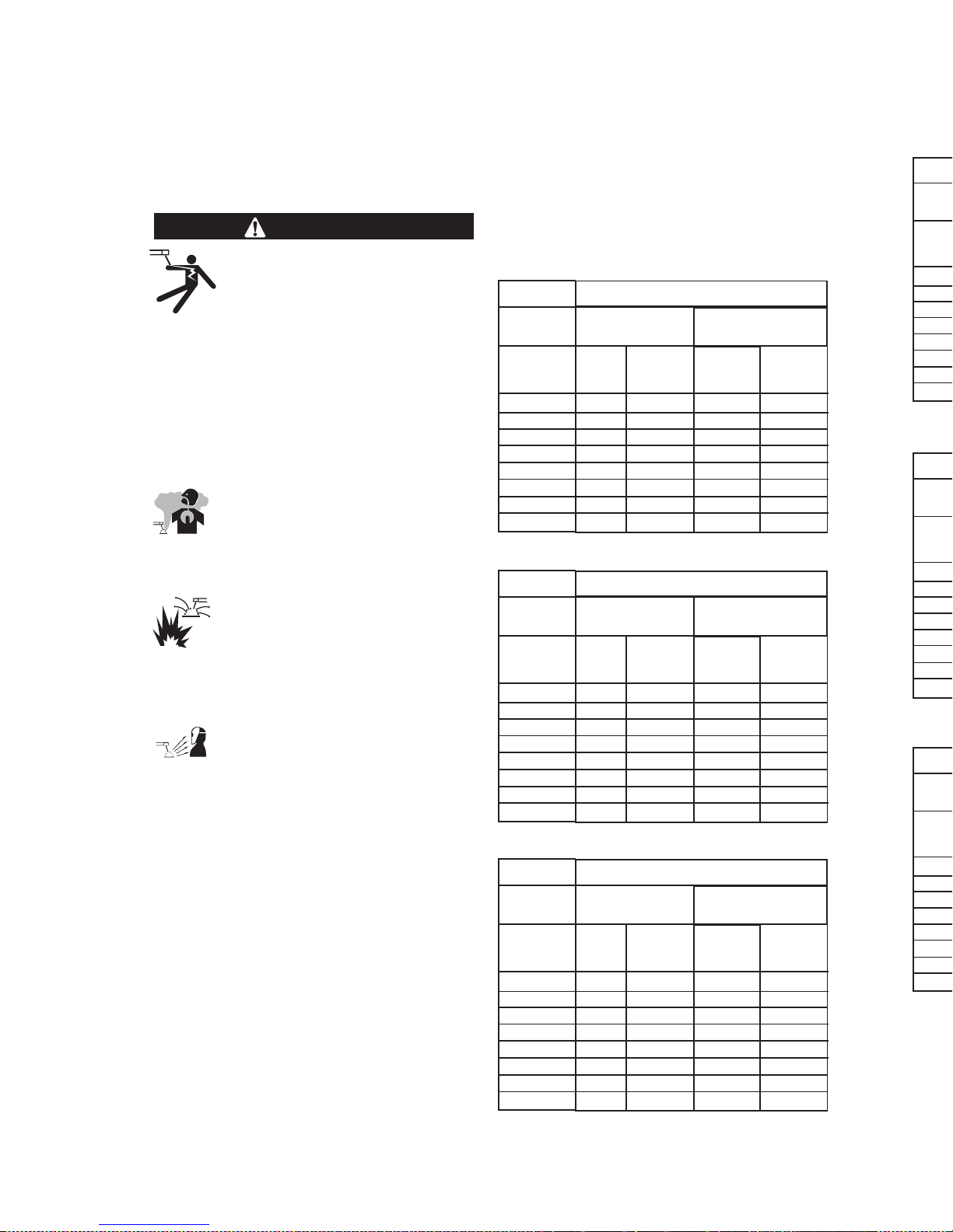
6. Cut off the aluminum wire so that it extends
about 1/4 inches from the contact tip.
7. CTWD (Contact Tip to Work Distance): Position
the gun so that the contact tip is nominally 3/8
inches from the joint and tilted with a push
angle toward it. The aluminum wire should not
contact the workpiece. (See figure B.1)
FIGURE B.1
8. Protect the eyes and pull the trigger to begin
welding.
9. Adjust the hand travel speed of the gun to
achieve a proper weld. The emerging wire
should stay within the molten puddle and not
overrun it. This speed also should not be so
slow that either the workpiece excessively
melts, or the weld bead becomes excessively
large.
10. Release the trigger to stop welding.
Alloy:
Wire Size:
Weldment
Thickness
22 ga
20 ga
18 ga
16 ga
14 ga
12 ga
10 ga
3/16 in.
Speed
2.5
2.5
4.5
5
6
7
N/A
N/A
Voltage
Tap
A
B
C
D
E
E
N/A
N/A
Speed
2
2
4
4.5
5
5.5
N/A
N/A
Voltage
Tap
A
B
C
D
E
E
N/A
N/A
0.030
0.035
5356
Weld-Pak 125 MACHINE
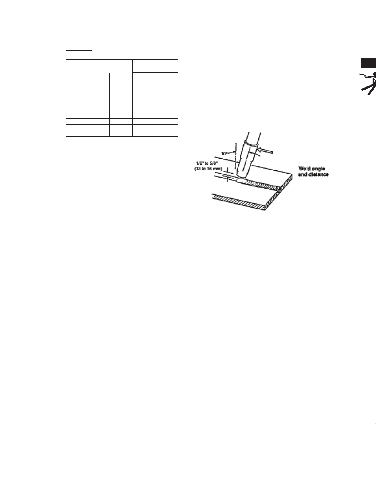
Pin No.
1
2
3
4
Function
Trigger
Trigger
+ Motor
- Motor
Gun Cable Lead Color
White
White
Red
Black
11
22
44
33
P6 CONNECTOR PINOUT
MASTER KEY
SAFETY PRECAUTIONS
ELECTRIC SHOCK can kill.
• Only qualified personnel
should perform this maintenance.
• Turn the input power OFF at the disconnect switch or fuse box before
working on this equipment.
• Do not touch electrically hot parts.
-----------------------------------------------------
ROUTINE AND PERIODIC
MAINTENANCE
RECOMMENDED TOOLS
• #2 Phillips screw-driver
• Slotted screw-driver
• 5/16 inch nut driver
• Torque Wrench
• Adjustable-jaw pliers
• 7/16 inch open-end wrench (gas diffuser)
• 9/16 inch open-end wrench (gun tube nut)
• Welding pliers (optional)
• Wire cutter
• Wire stripper
• Needle nose pliers
• Terminal crimping tool
• Flashlight
• Hand-held electrical meter *
• 3.0 mm metric allen wrench (drive roll
screw)
• Tape measure or 6-inch scale
• Tachometer (optional)
*Note: Two mete rs are used fo r s imultaneou sly
measuring drive motor’s voltage and current.
CLEANING AND INSPECTIONS
• Vacuum out any aluminum shavings that may
have accumulated inside of the gun. ( See
Correcting Wire Shaving Issues in this section).
• Wipe off dust and debris.
• Check that the gun tube and its lock nut are
properly tightened to the cable connector.
• Replace any warning or product identification
decals that have become illegible.
MAINTENANCE
D-1
WARNING
P6 CONNECTOR PIN-OUT
TABLE D.1
GAS DIFFUSER REPLACEMENT
This part may need to be replaced if it
has accumulated excessive spatter and
cannot be cleaned:
1. Remove gas nozzle and contact tip.
2. Carefully grasp gun tube with pliers
to prevent accidentally loosening gun
tube. Gas diffuser has right-hand
threads. Loosen gas diffuser with
wrench. (See Figure D.1)
FIGURE D.1
3. Install gas diffuser and thread into
place in gun tube. Tighten diffuser to
41 to 47 in.-lbs. with Torque Wrench.
Pin No.
1
2
3
4
Function
Trigger
Trigger
+ Motor
- Motor
Gun Cable Lead Color
White
White
Red
Black
11
22
44
33
P6 CONNECTOR PINOUT
MASTER KEY

MAINTENANCE
D-2
LINER ASSEMBLY REPLACEMENT
OR CLEANING
1. Replacement liner assemblies are factory-made to the correct length. No cutting is required. The same liner fits all
specified wire sizes and alloys:
2. Remove gas nozzle, contact tip, and
gas diff user (se e Ga s Di ff user
Replacement in this Section). Remove
spool cover.
3. Liner removal: Grasp liner with Needle
nose pliers at point A. Gently work liner
toward cable connector until the liner is
loose in it. Be careful not to scrape
liner’s gas-tight seal (point B) on connector. Withdraw liner out of gun tube
(arrow C). (See figure D.2)
FIGURE D.2
3a. Clean out old liner by blowing out with
shop air or obtain a new replacement
liner.
4. Slide liner, seal-end first, into gun tube.
Grasp liner with pliers at
A. Gently push liner into connector.
B. Check that liner passes through slot
in wire feeder.
C. Stop pushing when liner is 1.00 to
1.25 inches from end of gun tube.
(See figure D.3)
FIGURE D.3
5. Liner installation: See step 4 above.
6. Reinstall gas diffuser (see Figure D.1)
and thread into place. Allow the diffuser
to push the liner into its final position.
Tighten to 41 to 47 in.-lbs. with a torque
wrench.
7. Reinstall contact tip and gas nozzle.
DRIvE ROLL REPLACEMENT
1. The same drive roll fits all specified wire
sizes and alloys (See Table D.1).
2. Replace the drive roll if its fee din g
groove has become worn or cannot be
cleaned of galled aluminum.
3. Drive roll removal: Remove wire from
the wire drive. Unlock drive roll by rotating twist-lock in either direction. (See
figure D.4 and figure D.5) .
4. Twist-lock is rotated to the locked position, securing drive roll in place.
FIGURE D.4
5. Twist-lock is rotated to the unlocked
position, allowing drive roll removal.
FIGURE D.5
6. Drive roll may be removed with pliers, as
shown in figure D.6. It may be helpful to
relieve the idle roll tension during this
step.
FIGURE D.6
7. Clean the drive roll’s groove or obtain a
new replacement drive roll (if needed).
8. Install the drive roll by reversing the
above steps 1 thru 7. Either side of the
drive roll may be face-up.
IDLE ROLL ASSEMBLY
REPLACEMENT
1. Replace if it is degraded from use; for
example, it is becoming galled with alu-
minum deposits.
2. Remove drive roll. (See Maintenance
Section)
3. Remove both idle roll assembly retaining
screws and washers.(See figure D.7)
FIGURE D.7
4. Using Needle nose pliers, slowly pull the
idle roll assembly out of the wire drive by
equally working both sides of the tabbed
idle roll spring.
5. Insert the new idle roll assembly into the
wire drive with the correct orientation,
(See figures D.8 and D.9).
A
B
C
B
A
C
Twist-lock
Locked position
Twist-lock
Unlocked position

MAINTENANCE
D-3
6. Drive roll may be removed with pliers, as
shown in figure D.6. It may be helpful to
relieve the idle roll tension during this
step.
FIGURE D.6
7. Clean the drive roll’s groove or obtain a
new replacement drive roll (if needed).
8. Install the drive roll by reversing the
above steps 1 thru 7. Either side of the
drive roll may be face-up.
IDLE ROLL ASSEMBLY
REPLACEMENT
1. Replace if it is degraded from use; for
example, it is becoming galled with aluminum deposits.
2. Remove drive roll. (See Maintenance
Section)
3. Remove both idle roll assembly retaining
screws and washers.(See figure D.7)
FIGURE D.7
4. Using Needle nose pliers, slowly pull the
idle roll assembly out of the wire drive by
equally working both sides of the tabbed
idle roll spring.
5. Insert the new idle roll assembly into the
wire drive with the correct orientation,
(See figures D.8 and D.9).
Correct orientation. Note that lower spring is
not visible in bore of idle roll bearing at
arrow.
FIGURE D.8
Incorrect orientation. Note that lower spring
is visible in bore of idle roll bearing at arrow.
FIGURE D.9
6. Using Needle nose pliers, push the new
idle roll assembly into the wire drive until
it is fully seated.
7. Reinstall the retaining screws and washers. Do not use the screws to draw the
idle roll into place. Reinstall the drive roll
and wire into the wire drive.
GUN TUBE ASSEMBLY
REPLACEMENT
1. Replace if it is degraded from use; for
example, its insulating tube is breaking
down.
2. Rem ove lin er asse mbly. (S ee
Maintenance Section)
3. Remove left side of handle. Loosen gun
tube nut with wrench. Nut has right-hand
threads. Use adjustable pliers on gun tube
mounting plate to prevent cable assembly
from rotating in gun handle. (See figure
D.10)
FIGURE D.10
Idle Roll
Tension
Retaining screws
and washers
RIGHT
WRONG

MAINTENANCE
D-4
4. Obtain a new replacement gun tube (if needed). Remove locking nut from old gun tube and
install onto new gun tube. Nut should be fully
threaded finger-tight against the insulating
tube.
5. Slide gun tube’s external threads through gun
tube mounting plate and screw the gun tube by
hand into the cable connector until the nut pulls
the mounting plate snug against the connector.
6. Tighten the nut and mounting plate to the connector with Torque Wrench 10 to 12 ft.-lbs.
7. Reassemble gun. Be careful not to pinch any
leads between gun handle halves.
WIRE DRIvE ASSEMBLY REMOvAL AND
INSTALLATION
1. There are no serviceable or maintainable parts
inside of the wire drive.
2. Remove liner assembly (See Maintenance
Section figures D.2 and D.3).
3. Remove left side of handle.
4. Disconnect black and red leads from drive
motor. Use care to prevent damage to motor’s
fast-on electrical tabs.
5. Slide wire drive out of right handle half.
6. When reinstalling wire drive, note the proper
motor lead connection in the figure. Reconnect
red motor lead to positive (+) terminal, marked
with red dot at arrow. Reconnect black lead to
other motor terminal. (See figure D.11)
FIGURE D.11
7. Reassemble gun. Be careful not to pinch any
leads between gun handle halves.
2. Rem ove li ner as semb ly. (S e e Mai nten anc e
Section)
3. Remove gun tube assembly. (See Maintenance
Section)
4. Remove wire drive assembly. (See Maintenance
Section)
5. Disconnect trigger. Us e a djustable pl ie rs to
remove cable strain relief from right handle half.
(See figure D.13)
6. Pull damaged cable out of the right handle half.
The cable connector will fit through the strain relief
opening. Mark the new cable at a point 4.750 to
4.813 inches from the end of the cable connector.
(See figure D.14)
7. Place the strain relief onto the new cable at the
mark as shown in figure D.15.
TRIGGER ASSEMBLY REPLACEMENT
1. There are no serviceable or maintainable parts
inside of the trigger.
2. Remove spool cover and left side of handle.
3. Slide trigger out of right handle half. Disconnect
both white leads from trigger. Use care to prevent damage to electrical leads and the terminals. (See Figure D.12)
FIGURE D.12
4. Connect both white leads to the new trigger.
Either lead may be connected to either trigger
pin (non-polarized connections).
5. Slide new trigger into place and reassemble the
gun. Be careful not to pinch any leads between
gun handle halves.
WELDING CABLE ASSEMBLY
REPLACEMENT
1. Generally, there are no serviceable or maintain-
able parts, except for both o-rings on the
machine’s power and gas connector; these
seals may be replaced. However, there are
options:
• Damage to the four #22 AWG control leads at
the gun cable’s welding machine end (P6 plug)
may be repai rable w ithou t
removin g or
replacing the entire gun cable. The leads
can be spliced and soldered back together, and then reinsulated with heat-shrink
tubing. See Table D.1 in Maintenance
Section for a description of the connections.
• Otherwise, the damaged gun cable may
be replaced.
White Leads
Consumable
parts
Periodic
replacement
parts
Tapered contact tip 0.030(0.8mm) S28172-7
Tapered contact tip 0.035(0.9mm) S28172-1
Gas diffuser (S28722)
Gas nozzle (S28728-1)
Gun tube assembly (S28729-1)
Drive roll assembly (S26236-2)
Liner assembly (S26612)
KP2744-030T
KP2744-035T
KP3076-1
KP3075-1-50F
KP3325-1
KP2529-2
KP2632-1
10-pack
10-pack
1-piece
1-piece
1-piece
1-piece
1-piece
TABLE D.2
“+” Terminal
Red Dot
Black Lead

2. Rem ove li ner as semb ly. (S e e Mai nten anc e
Section)
3. Remove gun tube assembly. (See Maintenance
Section)
4. Remove wire drive assembly. (See Maintenance
Section)
5. Disconnect trigger. Us e a djustable pl ie rs to
remove cable strain relief from right handle half.
(See figure D.13)
FIGURE D.13
6. Pull damaged cable out of the right handle half.
The cable connector will fit through the strain relief
opening. Mark the new cable at a point 4.750 to
4.813 inches from the end of the cable connector.
(See figure D.14)
FIGURE D.14
7. Place the strain relief onto the new cable at the
mark as shown in figure D.15.
MAINTENANCE
D-5
Consumable
parts
Periodic
replacement
parts
Tapered contact tip 0.030(0.8mm) S28172-7
Tapered contact tip 0.035(0.9mm) S28172-1
Gas diffuser (S28722)
Gas nozzle (S28728-1)
Gun tube assembly (S28729-1)
Drive roll assembly (S26236-2)
Liner assembly (S26612)
KP2744-030T
KP2744-035T
KP3076-1
KP3075-1-50F
KP3325-1
KP2529-2
KP2632-1
10-pack
10-pack
1-piece
1-piece
1-piece
1-piece
1-piece
TABLE D.2
Mark for strain relief
FIGURE D.15
8. Install the new gun cable. Pass the cable connector through the opening in the right handle, seat
the strain relief in place, and then check to insure
the cable is not kinked between strain relief and
connector. Reassemble gun by reversing steps 2
through 5.
CORRECTING WIRE SHAvING ISSUES
1. If the inlet of the liner assembly is shaving the alu-
minum wire (the wire is usually peeled off in curled
chips) during feeding, the wire feed centerlines of
the wire drive and the liner itself may be misaligned.
• This misalignment may occur whenever the gun
tube, wire drive, or welding cable assemblies are
replaced.
• A limited amount of adjustment is available at the
gun tube mounting to possibly eliminate the shaving problem.
2. Visually check if wire is centered in the liner’s inlet
opening. Feed wire through the spool gun and note
which side the shaving seems to occur.
3. Remove left side of handle. See Figure D.10 Gun
Tube Replacement. Slightly loosen gun tube’s nut
as shown.
4. Slide the gun tube in the mounting plate’s hole to
realign the wire and then retighten the nut as
shown. Reassemble the gun.
5. Repeat steps 2 thru 4 until shaving is eliminated. A
light accumulation of fine dust is also permissible
after feeding 1/4 of a spool during welding use.
 Loading...