

Lincoln Electric K2803 Operator's Manual
IM2064
04/2017
REV01
POWER WAVE® AC/DC 1000 SD CE
OPERATOR’S MANUAL
ENGLISH
22801 St. Clair Ave., Cleveland Ohio 44117-1199 USA
THE LINCOLN ELECTRIC COMPANY
www.lincolnelectric.eu

THE LINCOLN ELECTRIC COMPANY
EC DECLARATION OF CONFORMITY
Manufacturer and technical documentation
holder:
Address:
EC Company:
Address:
Hereby declare that equipment:
The Lincoln Electric Company
22801 St. Clair Ave.
Cleveland Ohio 44117-1199 USA
Lincoln Electric Europe S.L.
c/o Balmes, 89 - 8
0 2a
08008 Barcelona
SPAIN
K2803, Power Wave AC/DC 1000 SD
K2444, CE Filter
K2814, MAXsa 10 Controller
K2626, MAXsa 19 Controller
K2370, MAXsa 22 Feed Head
K2312, MAXsa 29 Feed Head
(Sales codes may contain suffixes and prefixes.)
Is in conformity with Council Directives
and amendments:
Electromagnetic Compatibility (EMC) Directive 2014/30/EU
Low Voltage Directive (LVD) 2014/35/EU
Standards: EN 60974-1: 2012, Arc Welding Equipment – Part 1: Welding Power
Sources;
EN 60974-5: 2013, Arc Welding Equipment-Part 5: Wire Feeders;
EN 60974-10: 2014, Arc Welding Equipment-Part 10: Electromagnetic
compatibility (EMC) requirements;
CE marking affixed in 09
SamirFarah,Manufacturer DarioGatti,EuropeanCommunityRepresentative
ComplianceEngineeringManager EuropeanEngineeringManager
19January2017
MCD240f
20January2017
English English
I

THANKS! For having chosen the QUALITY of the Lincoln Electric products.
Please Examine Package and Equipment for Damage. Claims for material damaged in shipment must be notified
immediately to the dealer.
For future reference record in the table below your equipment identification information. Model Name, Code &
Serial Number can be found on the machine rating plate.
Model Name:
………………...…………………………….…………………………………………………………………………………………..
Code & Serial number:
………………….……………………………………………….. …………………………………………………….……………..
Date & Where Purchased:
…………………………………………………………………... ……………………….…………………………………………..
ENGLISH INDEX
Technical Specifications ...................................................................................................................................................... 1
Safety .................................................................................................................................................................................. 3
Installation and Operator Instructions ................................................................................................................................. 4
WEEE ................................................................................................................................................................................ 28
Spare Parts ....................................................................................................................................................................... 28
Authorized Service Shops Location .................................................................................................................................. 28
Electrical Schematic .......................................................................................................................................................... 29
Suggested Accessories ..................................................................................................................................................... 31
12/05
English English
II
3
W
Technical Specifications
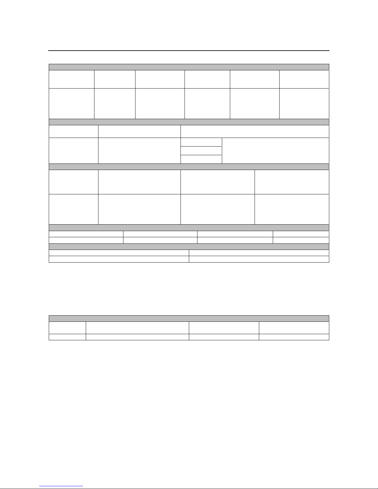
POWER WAVE® AC/DC 1000 SD CE (K2803-1*)
INPUT AT RATED OUTPUT – THREE PHASE ONLY
INPUT VOLTS 3
PHASE 50/60Hz
380
400
460
500
575
INPUT
CURRENT
AMPS
82
79
69
62
55
OUTPUT
CONDITIONS
1000A@44V.
100% Duty Cycle
IDLE POWER
WATTS
225 .95 86%
OUTPUT
OPEN CIRCUIT
VOLTAGE
71V
70VACpk.
AUXILIARY POWER (CIRCUIT
BREAKER PROTECTED)
40 VDC AT
10 AMPS
115 VAC AT
10 AMPS
PROCESS CURRENT RANGES (AC or DC)
SAW-DC+
SAW-DC-
SAW-AC
RECOMMENDED INPUT WIRE AND FUSES SIZES1
3 PAHESE INPUT
VOLTAGE
50/60Hz
380
400
460
500
575
TYPE 90°C COPPER WIRE
CONDUIT
AWG (mm
2
3 (25)
3 (25)
4 (25)
4 (25)
6 (16)
IN
COPPER GROUNDING
CONDUCTOR
)
AWG (mm2)
8 (10)
8 (10)
8 (10)
8 (10)
10 (6)
PHYSICAL DIMENSIONS
HEIGHT (mm) WIDTH (mm) DEPTH (mm)
1248 501 1184 363
TEMPERATURE RANGES
OPERATING TEMPERATURE RANGE (ºC) STORAGE TEMPERATURE RANGE (ºC)
-10 to +40 -40 to +85
1
Wire and Fuse Sizes based upon the U.S. National Electric Code and maximum output for 40°C ambient.
2
Also called “inverse time” or “thermal/magnetic” circuit breakers; circuit breakers that have a delay in tripping action that
decreases as the magnitude of current increases.
3
Fail to use proper type of copper wire will cause fire hazards.
*
An External filter will be required to meet CE or C-Tick/RCM conducted emission requirements. It will meet CE and C-
Tick/RCM requirements with the use of an optional external filter. (K2444-3 CE and C-Tick/RCM Filter Kit).
WELDING PROCESSES
PROCESS ELECTRODE DIAMETER RANGE
OUTPUR RANGE
(Amperes)
SAW 2 – 5.6mm 100 -1000 See Wire Drive Section
Insulation Class: Class F (155°C)
POWER FACTOR
@ RATED
OUTPUT
EFFICIENCY @
RATED OUTPUT
100amps@24Volts
1000Amps@44Volts
(Actual range may be limited by process)
TIME DELAY FUSER OR
BREAKER
AMPS
100
90
90
80
70
EIGHT (kg)
WIRE FEED SPEED
RANGE
2
English English
1
Electromagnetic Compatibility (EMC)
This machine has been designed in accordance with all relevant directives and standards. However, it may still generate
electromagnetic disturbances that can affect other systems like telecommunications (telephone, radio, and television) or
other safety systems. These disturbances can cause safety problems in the affected systems. Read and understand
this section to eliminate or reduce the amount of electromagnetic disturbance generated by this machine.
with, if necessary, assistance from Lincoln Electric.
Before installing the machine, the operator must check the work area for any devices that may malfunction because of
electromagnetic disturbances. Consider the following.
Input and output cables, control cables, and telephone cables that are in or adjacent to the work area and the
machine.
Radio and/or television transmitters and receivers. Computers or computer controlled equipment.
Safety and control equipment for industrial processes. Equipment for calibration and measurement.
Personal medical devices like pacemakers and hearing aids.
Check the electromagnetic immunity for equipment operating in or near the work area. The operator must be sure
that all equipment in the area is compatible. This may require additional protection measures.
The dimensions of the work area to consider will depend on the construction of the area and other activities that are
taking place.
Consider the following guidelines to reduce electromagnetic emissions from the machine.
Connect the machine to the input supply according to this manual. If disturbances occur if may be necessary to take
additional precautions such as filtering the input supply.
The output cables should be kept as short as possible and should be positioned together. If possible connect the
work piece to ground in order to reduce the electromagnetic emissions. The operator must check that connecting
the work piece to ground does not cause problems or unsafe operating conditions for personnel and equipment.
Shielding of cables in the work area can reduce electromagnetic emissions. This may be necessary for special
applications.
EMC classification of this product is class A in accordance with electromagnetic compatibility standard EN 60974-10 and
therefore the product is designed to be used in an industrial environment only.
The Class A equipment is not intended for use in residential locations where the electrical power is provided by the public
low-voltage supply system. There can be potential difficulties in ensuring electromagnetic compatibility in those locations,
due to conducted as well as radio-frequency disturbances.
This machine has been designed to operate in an industrial area. To operate in a domestic area it is
necessary to observe particular precautions to eliminate possible electromagnetic disturbances. The
operator must install and operate this equipment as described in this manual. If any electromagnetic
disturbances are detected the operator must put in place corrective actions to eliminate these disturbances
WARNING
WARNING
01/11
English English
2

Safety
11/04
WARNING
This equipment must be used by qualified personnel. Be sure that all installation, operation, maintenance and repair
procedures are performed only by qualified person. Read and understand this manual before operating this equipment.
Failure to follow the instructions in this manual could cause serious personal injury, loss of life, or damage to this
equipment. Read and understand the following explanations of the warning symbols. Lincoln Electric is not responsible
for damages caused by improper installation, improper care or abnormal operation.
WARNING: This symbol indicates that instructions must be followed to avoid serious personal injury,
loss of life, or damage to this equipment. Protect yourself and others from possible serious injury or
death.
READ AND UNDERSTAND INSTRUCTIONS: Read and understand this manual before operating
this equipment. Arc welding can be hazardous. Failure to follow the instructions in this manual could
cause serious personal injury, loss of life, or damage to this equipment.
ELECTRIC SHOCK CAN KILL: Welding equipment generates high voltages. Do not touch the
electrode, work clamp, or connected work pieces when this equipment is on. Insulate yourself from
the electrode, work clamp, and connected work pieces.
ELECTRICALLY POWERED EQUIPMENT: Turn off input power using the disconnect switch at the
fuse box before working on this equipment. Ground this equipment in accordance with local electrical
regulations.
ELECTRICALLY POWERED EQUIPMENT: Regularly inspect the input, electrode, and work clamp
cables. If any insulation damage exists replace the cable immediately. Do not place the electrode
holder directly on the welding table or any other surface in contact with the work clamp to avoid the
risk of accidental arc ignition.
ELECTRIC AND MAGNETIC FIELDS MAY BE DANGEROUS: Electric current flowing through any
conductor creates electric and magnetic fields (EMF). EMF fields may interfere with some
pacemakers, and welders having a pacemaker shall consult their physician before operating this
equipment.
CE COMPLIANCE: This equipment complies with the European Community Directives.
FUMES AND GASES CAN BE DANGEROUS: Welding may produce fumes and gases hazardous to
health. Avoid breathing these fumes and gases. To avoid these dangers the operator must use
enough ventilation or exhaust to keep fumes and gases away from the breathing zone.
ARC RAYS CAN BURN: Use a shield with the proper filter and cover plates to protect your eyes from
sparks and the rays of the arc when welding or observing. Use suitable clothing made from durable
flame-resistant material to protect you skin and that of your helpers. Protect other nearby personnel
with suitable, non-flammable screening and warn them not to watch the arc nor expose themselves to
the arc.
WELDING SPARKS CAN CAUSE FIRE OR EXPLOSION: Remove fire hazards from the welding
area and have a fire extinguisher readily available. Welding sparks and hot materials from the welding
process can easily go through small cracks and openings to adjacent areas. Do not weld on any
tanks, drums, containers, or material until the proper steps have been taken to insure that no
flammable or toxic vapors will be present. Never operate this equipment when flammable gases,
vapors or liquid combustibles are present.
WELDED MATERIALS CAN BURN: Welding generates a large amount of heat. Hot surfaces and
materials in work area can cause serious burns. Use gloves and pliers when touching or moving
materials in the work area.
SAFETY MARK: This equipment is suitable for supplying power for welding operations carried out in
an environment with increased hazard of electric shock.
English English
3
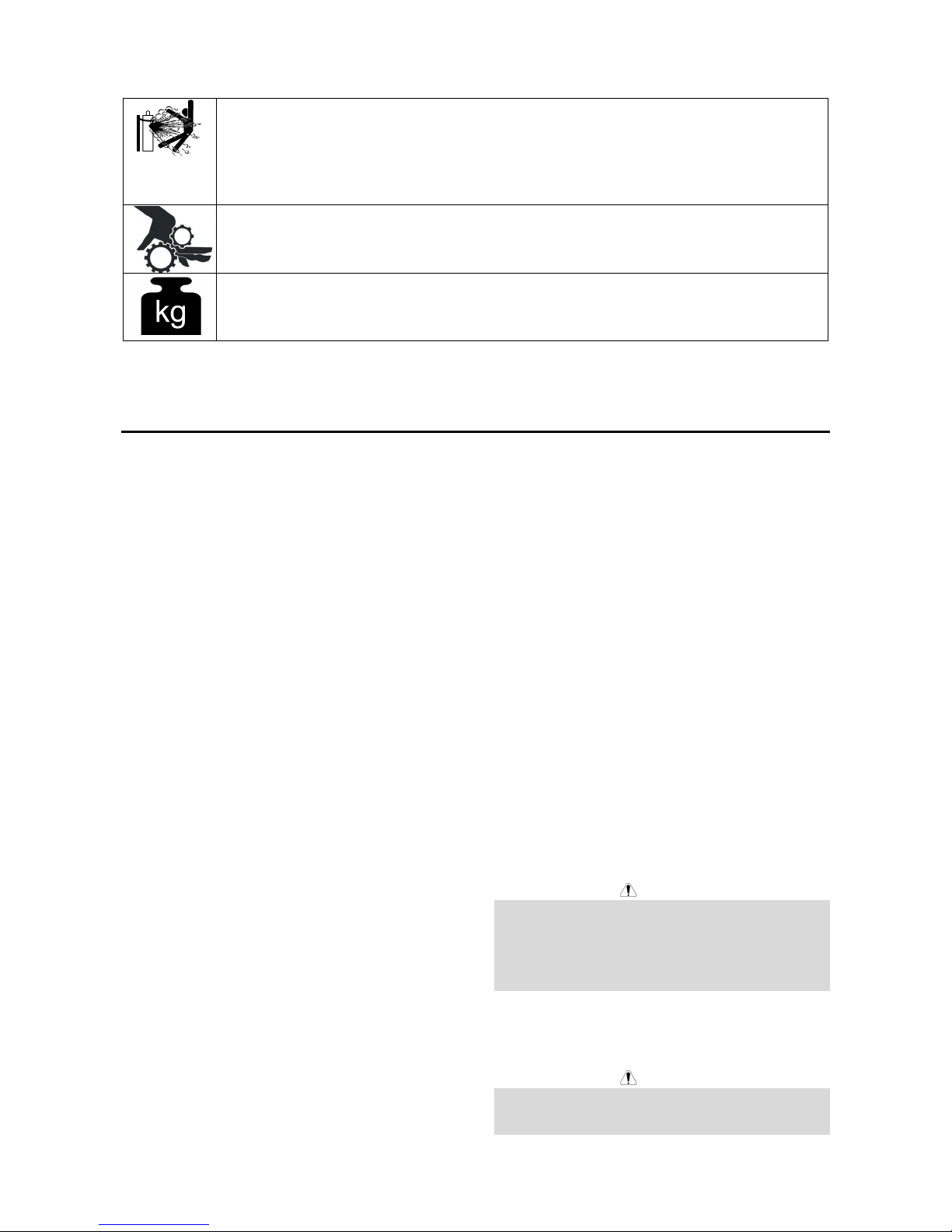
CYLINDER MAY EXPLODE IF DAMAGED: Use only compressed gas cylinders containing the
correct shielding gas for the process used and properly operating regulators designed for the gas and
pressure used. Always keep cylinders in an upright position securely chained to a fixed support. Do
not move or transport gas cylinders with the protection cap removed. Do not allow the electrode,
electrode holder, work clamp or any other electrically live part to touch a gas cylinder. Gas cylinders
must be located away from areas where they may be subjected to physical damage or the welding
process including sparks and heat sources.
MOVING PARTS ARE DANGEROUS: There are moving mechanical parts in this machine, which
can cause serious injury. Keep your hands, body and clothing away from those parts during machine
starting, operating and servicing.
EQUIPMENT WEIGHT OVER 30kg: Move this equipment with care and with the help of another
person. Lifting may be dangerous for your physical health.
The manufacturer reserves the right to make changes and/or improvements in design without upgrade at the same time
the operator’s manual.
Installation and Operator Instructions
Read this entire section before installation or operation
of the machine.
General Description
The Power Wave® AC/DC 1000 SD CE is a high
performance, digitally controlled inverter welding power
source. It is capable of producing a variable frequency
and amplitude AC output, DC positive output, or DC
negative output without the need for external
reconnection. It utilizes complex, high-speed waveform
control to support a variety of constant current and
constant voltage welding modes in each of its output
configurations.
The Power Wave
designed to be a part of a modular welding system. Each
welding arc may be driven by a single machine, or by a
number of machines in parallel. In multiple arc
applications the phase angle and frequency of different
machines can be synchronized by interconnecting the
units with a control cable to improve performance and
reduce the effects of arc blow.
The Power Wave
designed to interface with compatible ArcLink
equipment. However, it can also communicate with other
industrial machines and monitoring equipment via
DeviceNet, or Ethernet. The result is a highly integrated
and flexible welding cell.
®
AC/DC 1000 SD CE power source is
®
AC/DC 1000 SD CE is primarily
Recommended Process
The Power Wave® AC/DC 1000 SD CE is designed for
submerged arc welding (SAW). Due to its modular
design the Power Wave AC/DC can operate on either
single arc or in multi-arc applications with up to six arcs.
Each machine is factory preprogrammed with multiple
welding procedures to support all types of submerged
arc welding. The Power Wave
carries an output rating of 1000 amps, 44 volts (at 100%
duty cycle). If higher currents are required machines can
be easily paralleled for up to 3000 amps on each arc
(see Duty Cycle section)
®
AC/DC 1000 SD CE
Process Limitations
The Power Wave® AC/DC 1000 SD CE is suitable only
for the Submerged Arc Process (SAW).
Equipment Limitations
The Power Wave® AC/DC 1000 SD can be used in
outdoor environments. The Operating Temperature
Range is 14°F to 104°F(0°C to +40°C).
Only the MAXsa™ 22 or MAXsa™ 29 Wire Drives and
MAXsa™ 10 or MAXsa™ 19 Controllers may be used
with a K2803-1 PowerWave
Multi Arc system. Other Lincoln or non-Lincoln Wire
Drives can only be used with custom interfaces.
The Power Wave
maximum average output current of 1000 Amps at 100%
Duty Cycle.
®
AC/DC 1000 SD CE will support a
®
AC/DC 1000 SD CE in a
Location and Mounting
Place the welder where clean cooling air can freely
circulate in through the rear louvers and out through the
case sides and front. Dirt, dust, or any foreign material
that can be drawn into the welder should be kept at a
minimum. Failure to observe these precautions can
result in excessive operating temperatures and nuisance
shutdowns. See the Clearance Requirements and Figure
#1 below.
Stacking
DO NOT MOUNT OVER COMBUSTIBLE SURFACES.
Where there is a combustible surface directly under
stationary or fixed electrical equipment, the surface shall
be covered with a steel plate at least 1.6mm thick, which
shall extend not more than 150mm beyond the
equipment on all sides.
The Power Wave
be stacked.
WARNING
®
AC/DC 1000 SD CE machine cannot
Lifting
FALLING EQUIPMENT can cause injury.
Lift only with equipment of adequate lifting capacity.
Be sure machine is stable when lifting.
WARNING
English English
4
Do not lift this machine using lift bail if it is equipped
with a heavy accessory such as trailer or gas
cylinder.
Do not lift machine if lift bail is damaged.
Do not operate machine while suspended from lift
bail
Lift the machine by the lift bail only. The lift bail is
designed to lift the power source only . Do not attempt to
lift the Power Wave
accessories attached to it.
®
AC/DC 1000 SD CE with
Duty Cycle
The Power Wave® AC/DC 1000 SD CE is capable of
welding 1000Amps,. @44V, at a 100% Duty cycle.
Environmentasl Limitations
The Power Wave® AC/DC 1000 SD CE can be used in
an outdoor environment with an IP 23 rating. It should
not be subjected to falling water, nor should any parts of
it be submerged in water. Doing so may cause improper
operation as well as pose a safety hazard. The best
practice is to keep the machine in a dry, sheltered area.
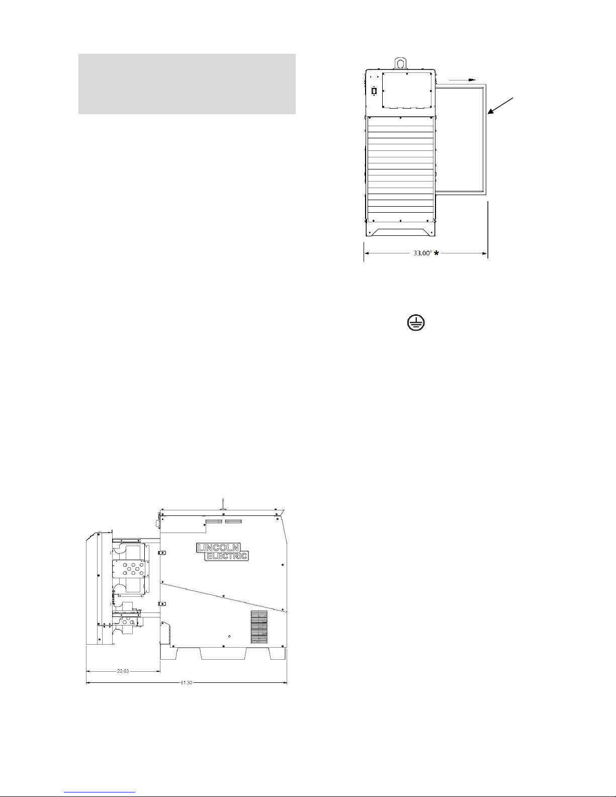
Clearence Requirements
The maintenance requirements of the Power Wave®
AC/DC 1000 SD CE demands that enough clearance
behind the machine be maintained. This is especially
important where more than one machine is to be used or
if the machines are going to be rack mounted.
The rear portion of the machine that contains the filter
and the cooling fans slides out for easy access to clean
the heat sink fins.
Removing the four clips and pulling back on the rear
portion of the machine will provide access for cleaning
the machine and checking the filter. The filter is removed
from the right side of the machine.
Where machines are mounted side by side, the machine
that is furthest to the right will need to have the indicated
clearance to the right side for filter removal. See Figure
#1
FILTER REMOVAL
FROM SIDE OF
MACHINE
*: 33.00” width needed for filter maintenance access.
Figure #1: Clearance Requirements
Input and Ground Connections
Machine Grounding
The frame of the welder must be grounded. A ground
terminal marked with a ground symbol shown is located
inside the reconnect/input access door for this purpose.
See your local and national electrical codes for proper
grounding methods.
English English
5
Input Connection
WARNING
ELECTRIC SHOCK can kill
Only a qualified electrician should connect the input
leads to the Power Wave. Connections should be made
in accordance with all local and national electrical codes
and the connection diagrams located on the inside of the
reconnect/input access door of the machine. Failure to
do so may result in bodily injury or death.
Use a three-phrase supply line. A 45mm diameter
access hole for the input supply is located on the case
back. Connect L1, L2, L3 and ground according to the
Input Supply Connection Diagram.
Input Fuse and Supply Wire
Considerations
Refer to Specifications page for recommended fuse and
wire sizes. Fuse the input circuit with the recommended
super lag fuse or delay type breakers (also called
"inverse time" or "thermal/magnetic" circuit breakers).
Choose input and grounding wire size according to local
or national electrical codes. Using fuses or circuit
breakers smaller than recommended may result in
"nuisance" shut-offs from welder inrush currents, even if
the machine is not being used at high currents.
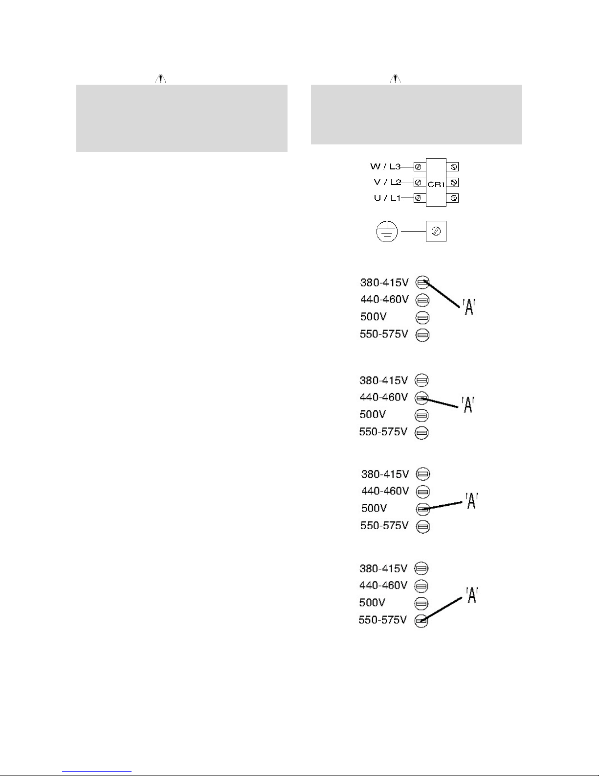
Input Voltage Selection
Welders are shipped connected for the highest input
voltage listed on the rating plate. To move this
connection to a different input voltage, see the diagram
located on the inside of the input access door, or the
Input Supply Connection Diagram below. If the Auxiliary
lead (indicated as ‘A’) is placed in the wrong position,
there are two possible results.
a) If the lead is placed in a position higher than the
applied line voltage, the welder may not come on at
all.
b) If the Auxiliary lead is placed in a position lower than
the applied line voltage, the welder will not come on,
and the two circuit breakers in the reconnect area
will open. If this occurs, turn off the input voltage,
properly connect the auxiliary lead, reset the
breakers, and try again.
Input Supply Connection for K2803-1
ELECTRIC SHOCK CAN KILL:
Do not operate with covers removed
Disconnect input power before servicing
Do not touch electrically live parts
Only qualified persons should install, use or service
this equipment
Voltage=380-415V
Voltage=440-460V
Voltage=500V
WARNING
English English
Voltage=550-575V
6
System Connection
System Overview
The Power Wave® AC/DC 1000 SD CE power source is
designed to be a part of a modular welding system
typically controlled by a MAXsa™ 10 Controller or a
customer supplied Programmable Logic Controller
(PLC). Each welding arc may be driven by a single
power source or by a number of power sources
connected in parallel. The actual number of power
sources per arc will vary depending on the application.
When only one power source is required for an arc
group, it must be configured as a Master. When parallel
machines are required, one is designated as the Master
and the rest as Slaves. The synchronizing connectors for
paralleled machines are on the back of the power
source. The Master controls the AC switching for the arc
group, and the Slaves respond accordingly. See Figure
#3 below.
When employed in a multi-arc AC system the arcs must
be synchronized to each other. The Master for each arc
can be configured to follow a dedicated external
synchronization signal to determine its frequency and
balance. The Synchronizing Connectors on the back of
the Power Wave
means to synchronize the AC wave shapes of up to six
different arcs to a common carrier frequency. (See
Figure #3). This frequency can range from 20 hertz to
100 hertz. It can also control the phase angle between
arcs to reduce the effects of welding related issues such
as "Arc Blow".
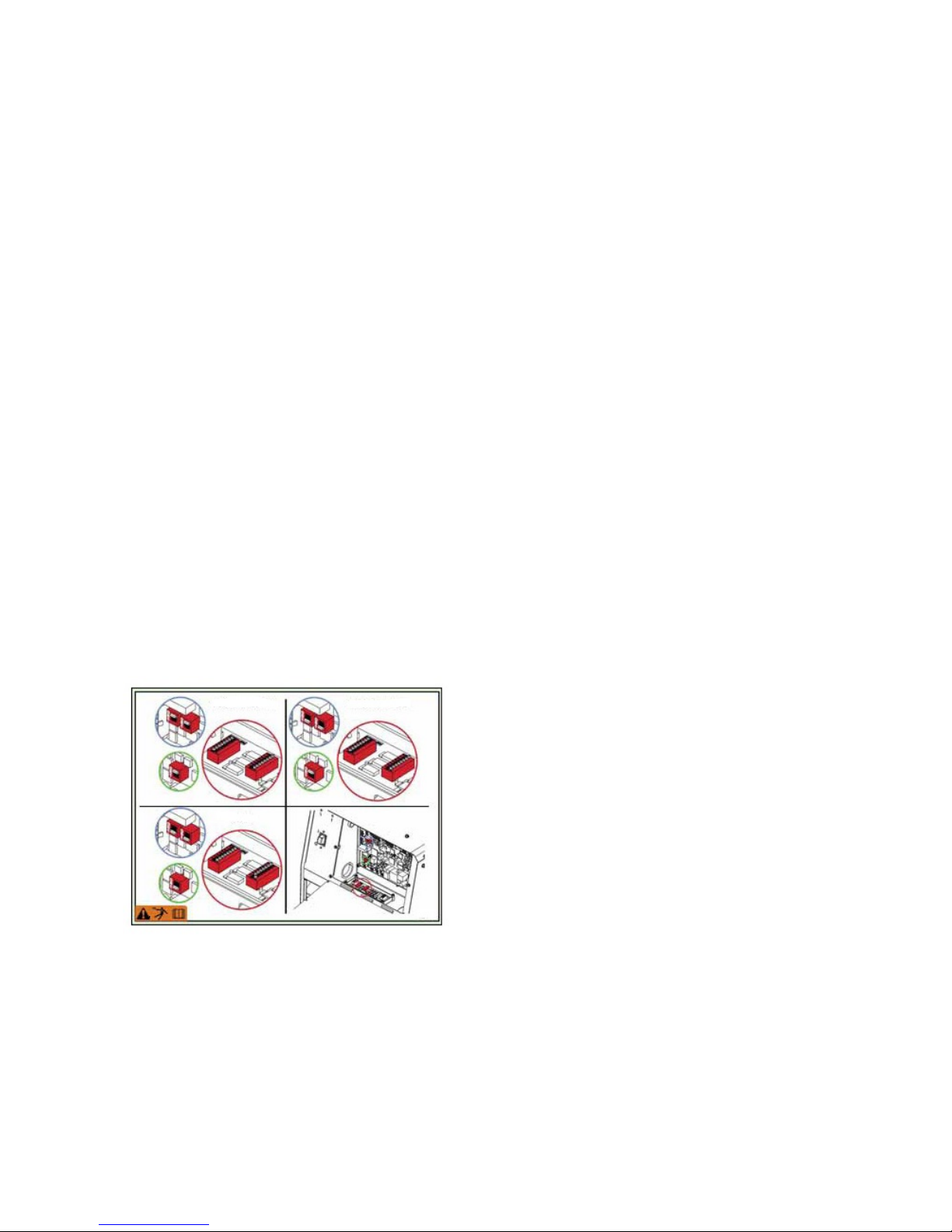
The arc to arc phase relationship is determined by the
timing of each arc’s "sync" signal relative to the "sync"
signal of ARC 1. DIP Switches on the Control PC Board
of each machine must be set to identify it as a Master
Lead, Master Trail or Slave. See Figure #2.
®
AC/DC 1000 SD CE provide the
NOTE: The K2803-1 Power Wave® AC/DC 1000® SD
is backwards compatible with the K2344-2 Power
Wave® AC/DC 1000 in tandem or multi-arc systems.
The K2803- 1 and K2344-2 machines cannot be
connected in parallel. Paralleled machines must be of
the same type. A K1805- 1 (14 to 22 pin adapter cable)
is required to interface to the K2282-1 Systems Interface
in these setups A PLC interface is an alternate method
of control for larger systems. The PLC is typically
connected via DeviceNet directly to the Master power
source of each arc group in the system. MAXsa™ 19
Controller is still required to power the Wire Drive.
Contact your Local Lincoln Electric Representative for
more information.
The connection diagrams describe the layout of several
typical systems including Multi-Arc and Paralleled
machine set-ups. Each system also has a step by step
“Installation Checklist”.
MASTER-LEAD MASTER-TRAIL
SLAVE
Figure #2: Dip Switch Settings
In a typical multi-arc system, each arc is controlled by its
own MAXsa™10 Controller. The basic characteristics of
the individual arcs such as WFS, amplitude, and offset
are set locally by each arc’s dedicated controller. The
frequency, balance, and phase shift parameters of each
arc are controlled by the MAXsa™ 10 Controller for ARC
1 (Master Lead).
English English
7
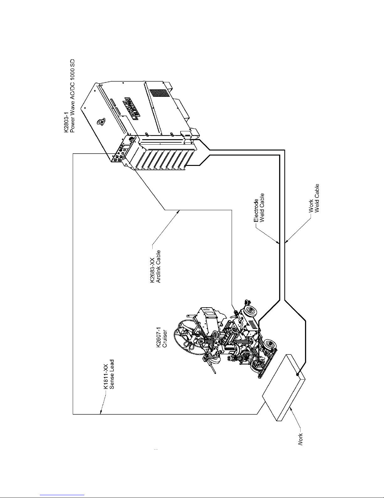
Cruiser Connection Diagram
English English
8
 Loading...