

Lincoln Electric K2613-5, K2613-7, LN-25 PRO Operator's Manual
LN-25™ PRO
OPERATOR’S MANUAL
IM2071
10/2017
REV01
ENGLISH
22801 St. Clair Ave., Cleveland Ohio 44117-1199 USA
THE LINCOLN ELECTRIC COMPANY
www.lincolnelectric.eu

THE LINCOLN ELECTRIC COMPANY
EC DECLARATION OF CONFORMITY
Manufacturer and technical documentation
holder:
Address:
EC Company:
Address:
Hereby declare that welding equipment:
Product Numbers:
Is in conformity with Council Directives and
amendments:
Low Voltage Directive 2014/35/EU
Standards: EN 60974-5: 2013, Arc Welding Equipment – Part 5: Wire Feeders,
CE marking affixed in 08
Samir Farah, Manufacturer Dario Gatti, European Community Representative
Compliance Engineering Manager European Engineering Director Machines
17 May 2016 19 May 2016
MCD143e
The Lincoln Electric Company
22801 St. Clair Ave.
Cleveland Ohio 44117-1199 USA
Lincoln Electric Europe S.L.
c/o Balmes, 89 - 80 2a
08008 Barcelona
SPAIN
LN-25 PRO & LN-25 PRO Dual, Wire Feeders
K2613 & K2614
(Product numbers may also contain prefixes and suffixes)
Electromagnetic Compatibility (EMC) Directive 2014/30/EU
EN 60974-10: 2007 Arc Welding Equipment – Part 10:
Electromagnetic compatibility (EMC) requirements;
English English
I

THANKS! For having chosen the QUALITY of the Lincoln Electric products.
Please Examine Package and Equipment for Damage. Claims for material damaged in shipment must be notified
immediately to the dealer.
For future reference record in the table below your equipment identification information. Model Name, Code &
Serial Number can be found on the machine rating plate.
Model Name:
………………...…………………………….…………………………………………………………………………………………..
Code & Serial number:
………………….……………………………………………….. …………………………………………………….……………..
Date & Where Purchased:
…………………………………………………………………... ……………………….…………………………………………..
ENGLISH INDEX
Technical specifications ...................................................................................................................................................... 1
Electromagnetic Compatibility (EMC) ................................................................................................................................. 2
Safety .................................................................................................................................................................................. 3
Installation and Operator Instructions ................................................................................................................................. 4
WEEE ................................................................................................................................................................................ 18
Spare Parts ....................................................................................................................................................................... 18
Authorized Service Shops Location .................................................................................................................................. 18
Electrical Schematic .......................................................................................................................................................... 19
Suggested Accessories ..................................................................................................................................................... 20
12/05
English English
II
Technical specifications
LN-25™ PRO (K2613-5, K2613-7) (CODE NUMBER: 11746, 11747).
INPUT VOLTAGE AND CURRENT
INPUT VOLTAGE ± 10% INPUT AMPERES
DUTY CYCLE INPUT AMPERES
60% RATING 450
GEARING - WIRE FEED SPEED RANGE-WIRE SIZE
GEARING
EXTRA TORQUE K2613-7
STANDARD SPEED
K2613-5
HEIGHT WIDTH DEPTH WEIGHT
14.8 INCHES
(376 MM)
HANDLE FOLDED DOWN
15-110 VDC
4A
RATED OUTPUT @ 104°F (40°C)
GMAW FCAW
WFS RANGE WIRE SIZES WFS RANGE WIRE SIZES
50 – 400 IPM
(1.3 – 10.1M/MIN)
50 – 700 IPM
(1.3 – 17.7M/MIN)
.023 – 1/16"
(0.6 – 1.6MM)
.023 – 1/16"
(0.6 – 1.6MM)
50 – 400 IPM
(1.3 – 10.1M/MIN)
50 – 700 IPM
(1.3 – 17.7M/MIN)
.030 - 3/32”
(0.8 – 2.4MM)
.030 - 5/64
(0.8 - 2.0MM)
PHYSICAL DIMENSIONS
8.7 INCHES
( 221 MM)
23.2 INCHES
(589 MM)
38 LBS
(17 KG)
TEMPERATURE RANGE
OPERATION: STORAGE:
Thermal tests have been performed at ambient temperature. The duty cycle (duty factor) at 40°C has been
determined by simulation.
Duty cycle is based upon the amount of welding performed in a 10 minute period.
-40°F TO 104°F (-40°C TO 40°C)
-40°F TO 122°F (-40°C TO 50°C)
IP23
IEC 60974-5
English English
1

Electromagnetic Compatibility (EMC)
This machine has been designed in accordance with all relevant directives and standards. However, it may still generate
electromagnetic disturbances that can affect other systems like telecommunications (telephone, radio, and television) or
other safety systems. These disturbances can cause safety problems in the affected systems. Read and understand
this section to eliminate or reduce the amount of electromagnetic disturbance generated by this machine.
with, if necessary, assistance from Lincoln Electric.
Before installing the machine, the operator must check the work area for any devices that may malfunction because of
electromagnetic disturbances. Consider the following.
Input and output cables, control cables, and telephone cables that are in or adjacent to the work area and the
machine.
Radio and/or television transmitters and receivers. Computers or computer controlled equipment.
Safety and control equipment for industrial processes. Equipment for calibration and measurement.
Personal medical devices like pacemakers and hearing aids.
Check the electromagnetic immunity for equipment operating in or near the work area. The operator must be sure
that all equipment in the area is compatible. This may require additional protection measures.
The dimensions of the work area to consider will depend on the construction of the area and other activities that are
taking place.
Consider the following guidelines to reduce electromagnetic emissions from the machine.
Connect the machine to the input supply according to this manual. If disturbances occur if may be necessary to take
additional precautions such as filtering the input supply.
The output cables should be kept as short as possible and should be positioned together. If possible connect the
work piece to ground in order to reduce the electromagnetic emissions. The operator must check that connecting
the work piece to ground does not cause problems or unsafe operating conditions for personnel and equipment.
Shielding of cables in the work area can reduce electromagnetic emissions. This may be necessary for special
applications.
EMC classification of this product is class A in accordance with electromagnetic compatibility standard EN 60974-10 and
therefore the product is designed to be used in an industrial environment only.
The Class A equipment is not intended for use in residential locations where the electrical power is provided by the public
low-voltage supply system. There can be potential difficulties in ensuring electromagnetic compatibility in those locations,
due to conducted as well as radio-frequency disturbances.
This machine has been designed to operate in an industrial area. To operate in a domestic area it is
necessary to observe particular precautions to eliminate possible electromagnetic disturbances. The
operator must install and operate this equipment as described in this manual. If any electromagnetic
disturbances are detected the operator must put in place corrective actions to eliminate these disturbances
WARNING
WARNING
01/11
English English
2
Safety
11/04
WARNING
This equipment must be used by qualified personnel. Be sure that all installation, operation, maintenance and repair
procedures are performed only by qualified person. Read and understand this manual before operating this equipment.
Failure to follow the instructions in this manual could cause serious personal injury, loss of life, or damage to this
equipment. Read and understand the following explanations of the warning symbols. Lincoln Electric is not responsible
for damages caused by improper installation, improper care or abnormal operation.
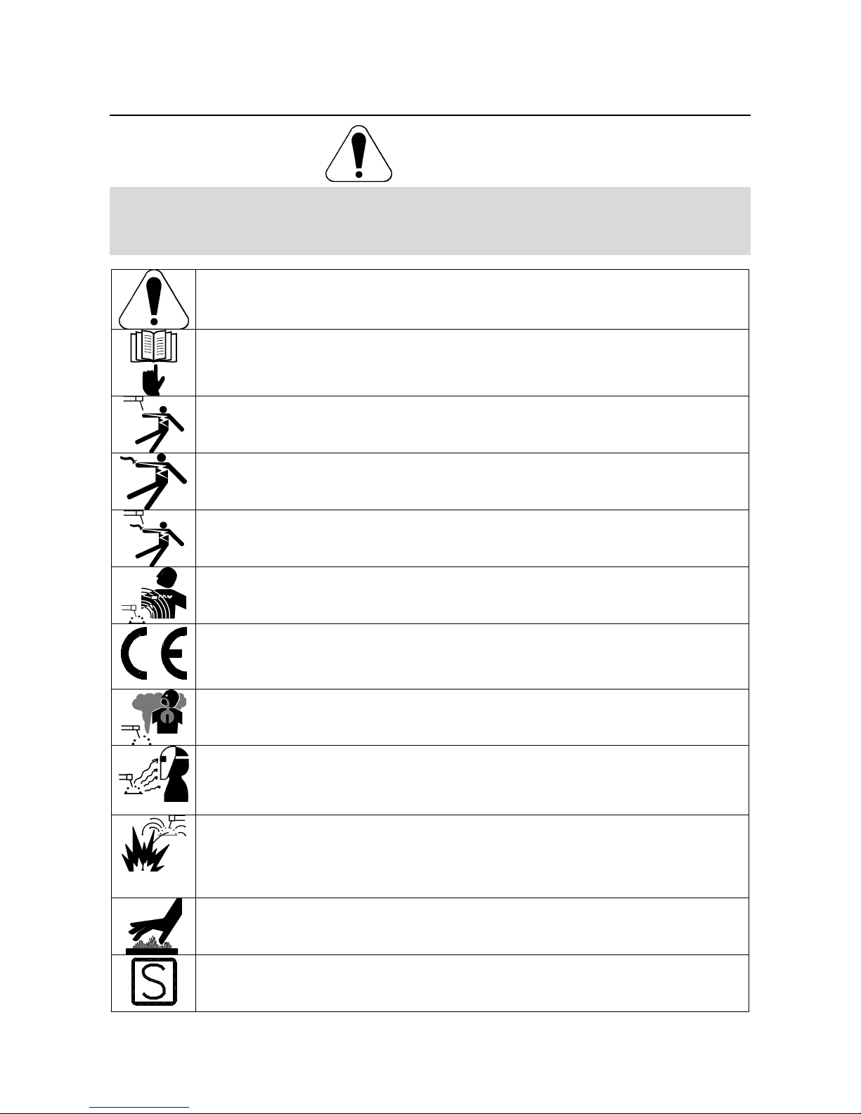
WARNING: This symbol indicates that instructions must be followed to avoid serious personal injury,
loss of life, or damage to this equipment. Protect yourself and others from possible serious injury or
death.
READ AND UNDERSTAND INSTRUCTIONS: Read and understand this manual before operating this
equipment. Arc welding can be hazardous. Failure to follow the instructions in this manual could cause
serious personal injury, loss of life, or damage to this equipment.
ELECTRIC SHOCK CAN KILL: Welding equipment generates high voltages. Do not touch the
electrode, work clamp, or connected work pieces when this equipment is on. Insulate yourself from the
electrode, work clamp, and connected work pieces.
ELECTRICALLY POWERED EQUIPMENT: Turn off input power using the disconnect switch at the
fuse box before working on this equipment. Ground this equipment in accordance with local electrical
regulations.
ELECTRICALLY POWERED EQUIPMENT: Regularly inspect the input, electrode, and work clamp
cables. If any insulation damage exists replace the cable immediately. Do not place the electrode
holder directly on the welding table or any other surface in contact with the work clamp to avoid the
risk of accidental arc ignition.
ELECTRIC AND MAGNETIC FIELDS MAY BE DANGEROUS: Electric current flowing through any
conductor creates electric and magnetic fields (EMF). EMF fields may interfere with some
pacemakers, and welders having a pacemaker shall consult their physician before operating this
equipment.
CE COMPLIANCE: This equipment complies with the European Community Directives.
FUMES AND GASES CAN BE DANGEROUS: Welding may produce fumes and gases hazardous to
health. Avoid breathing these fumes and gases. To avoid these dangers the operator must use
enough ventilation or exhaust to keep fumes and gases away from the breathing zone.
ARC RAYS CAN BURN: Use a shield with the proper filter and cover plates to protect your eyes from
sparks and the rays of the arc when welding or observing. Use suitable clothing made from durable
flame-resistant material to protect you skin and that of your helpers. Protect other nearby personnel
with suitable, non-flammable screening and warn them not to watch the arc nor expose themselves to
the arc.
WELDING SPARKS CAN CAUSE FIRE OR EXPLOSION: Remove fire hazards from the welding area
and have a fire extinguisher readily available. Welding sparks and hot materials from the welding
process can easily go through small cracks and openings to adjacent areas. Do not weld on any
tanks, drums, containers, or material until the proper steps have been taken to insure that no
flammable or toxic vapors will be present. Never operate this equipment when flammable gases,
vapors or liquid combustibles are present.
WELDED MATERIALS CAN BURN: Welding generates a large amount of heat. Hot surfaces and
materials in work area can cause serious burns. Use gloves and pliers when touching or moving
materials in the work area.
SAFETY MARK: This equipment is suitable for supplying power for welding operations carried out in
an environment with increased hazard of electric shock.
English English
3
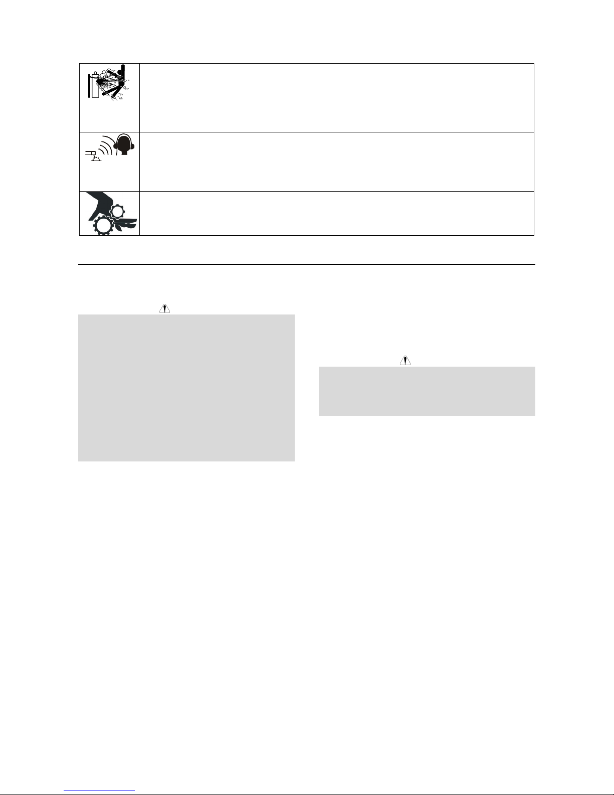
CYLINDER MAY EXPLODE IF DAMAGED: Use only compressed gas cylinders containing the correct
shielding gas for the process used and properly operating regulators designed for the gas and
pressure used. Always keep cylinders in an upright position securely chained to a fixed support. Do
not move or transport gas cylinders with the protection cap removed. Do not allow the electrode,
electrode holder, work clamp or any other electrically live part to touch a gas cylinder. Gas cylinders
must be located away from areas where they may be subjected to physical damage or the welding
process including sparks and heat sources.
NOISE APPEARES DURING WELDING CAN BE HARMFUL: Welding arc can cause noise with high
level of 85dB for 8-hour week day. Welders operating welding machines are obligated to wear the
proper ear protectors /appendix No. 2 for the Decree of the Secretary of Labor and Social Policy from
17.06 1998 – Dz.U. No. 79 pos. 513/. According to the Decree the Secretary of Health and Social
Welfare from 09.07.1996 /Dz.U. No. 68 pos. 194/, employers are obligated to carry examinations and
measurements of health harmful factors.
MOVING PARTS ARE DANGEROUS: There are moving mechanical parts in this machine, which can
cause serious injury. Keep your hands, body and clothing away from those parts during machine
starting, operating and servicing.
Installation and Operator Instructions
Read this entire section before installation or operation
of the machine.
WARNING
ELECTRIC SHOCK CAN KILL.
• Turn the input power OFF at the disconnect switch or
fuse box before attempting to connect or disconnect
input power lines, output cables or control cables.
• Only qualified personnel should perform this
installation.
• Do not touch metal portions of the LN-25™ PRO
work clip when the welding power source is on.
• Do not attach the work clip to the wire feeder.
• Connect the work clip directly to the work, as close
as possible to the welding arc.
• Turn power off at the welding power source before
disconnecting the work clip from the work.
• Only use on power sources with open circuit voltages
less than 110 VDC.
Location
For best wire feeding performance, place the LN- 25™
Pro on a stable and dry surface. Keep the wire feeder in
a vertical position. Do not operate the wire feeder on an
angled surface of more than 15 degrees.
Do not submerge the LN-25™ Pro.
The LN-25™ Pro is rated IP23 and is suitable for
outdoor use.
The handle of the LN-25™ Pro is intended for moving
the wire feeder about the work place only.
When suspending a wire feeder, insulate the hanging
device from the wire feeder enclosure.
High Frequency Protection
Locate the LN-25™ PRO away from radio controlled
machinery. The normal operation of the LN-25™ PRO
may adversely affect the operation of RF controlled
equipment, which may result in bodily injury or damage
to the equipment.
Weld cable size
Table 1 located below are copper cable sizes
recommended for different currents and duty cycles.
Lengths stipulated are the distance from the welder to
work and back to the welder again. Cable sizes are
increased for greater lengths primarily for the purpose of
minimizing cable drop.
Electrode lead
The electrode lead is a 4/0 cable.
WARNING
English English
4

RECOMMENDED CABLE SIZES (RUBBER COVERED COPPER - RATED 167°F OR 75°C)**
CABLE SIZES FOR COMBINED LENGTHS OF ELECTRODE AND WORK
CABLES
0 to 50 Ft.
(0 to15m)
2
2
4 or 5
3
3
50 to 100 Ft.
(15 to 30m)
2
2
3
3
3
100 to 150 Ft.
(30 to 46m)
2
2
2
2
2
150 to 200 Ft.
(46 to 61m)
1
1
1
1
1
AMPERES
200
200
225
225
250
PERCENT
DUTY
CYCLE
60
100
20
40 & 30
30
200 to 250 Ft.
(61 to 76m)
1/0
1/0
1/0
1/0
1/0
250
250
250
300
325
350
400
400
500
** Tabled values are for operation at ambient temperatures of 104°F(40°C) and below. Applications above 104°F(40°C) may require
cables larger than recommended, or cables rated higher than 167°F(75°C).
40
60
100
60
100
60
60
100
60
2
1
1
1
2/0
1/0
2/0
3/0
2/0
2
1
1
1
2/0
1/0
2/0
3/0
2/0
1
1
1
1
2/0
2/0
2/0
3/0
3/0
1
1
1
1/0
2/0
2/0
3/0
3/0
3/0
1/0
1/0
1/0
2/0
3/0
3/0
4/0
4/0
4/0
Table 1
Shielding gas connection
WARNING
CYLINDER MAY EXPLODE IF DAMAGED.
• Keep cylinder upright and chained to support.
• Keep cylinder away from areas where it may be
damaged.
• Never lift welder with cylinder attached.
• Never allow welding electrode to touch cylinder.
• Keep cylinder away from welding or other live
electrical circuits.
• BUILD UP OF SHIELDING GAS MAY HARM
HEALTH OR KILL.
• Shut off shielding gas supply when not in use.
• See American National Standard z-49.1, "Safety in
Welding and Cutting” Published by the American
Welding Society.
Maximum inlet pressure is 100 psi. (6.9 bar.)
Install the shielding gas supply as follows:
1. Secure the cylinder to prevent it from falling.
2. Remove the cylinder cap. Inspect the cylinder valves
and regulator for damaged threads, dirt, dust, oil or
grease. Remove dust and dirt with a clean cloth. DO
NOT ATTACH THE REGULATOR IF OIL, GREASE
OR DAMAGE IS PRESENT! Inform your gas
supplier of this condition. Oil or grease in the
presence of high pressure oxygen is explosive.
3. Stand to one side away from the outlet and open the
cylinder valve for an instant. This blows away any
dust or dirt which may have accumulated in the valve
outlet.
4. Attach the flow regulator to the cylinder valve and
tighten the union nut(s) securely with a wrench. Note:
if connecting to 100% CO2 cylinder, insert regulator
adapter between regulator and cylinder valve. If
adapter is equipped with a plastic washer, be sure it
is seated for connection to the CO2 cylinder.
5. Attach one end of the inlet hose to the outlet fitting of
the flow regulator. Attach the other end to the
welding system shielding gas inlet. Tighten the union
nuts with a wrench.
6. Before opening the cylinder valve, turn the regulator
adjusting knob counterclockwise until the adjusting
spring pressure is released.
7. Standing to one side, open the cylinder valve slowly
a fraction of a turn. When the cylinder pressure gage
stops moving, open the valve fully.
8. The flow regulator is adjustable. Adjust it to the flow
rate recommended for the procedure and process
being used before making a weld.
Wire drive configuration
(See Figure 1)
Gun bushing, thumb screw and socket head
cap screw
WARNING
ELECTRIC SHOCK CAN KILL.
• Turn the input power OFF at the welding power
source before installation or changing drive rolls
and/or guides.
• Do not touch electrically live parts.
• When inching with the gun trigger, electrode and
drive mechanism are "hot" to work and ground and
could remain energized several seconds after the
gun trigger is released.
• Do not operate with covers, panels or guards
removed or open.
• Only qualified personnel should perform
maintenance work.
English English
5
 Loading...