

Lincoln Electric RANGER 305D CE, K2279-1, K2279-2, K2279-3 Operator's Manual
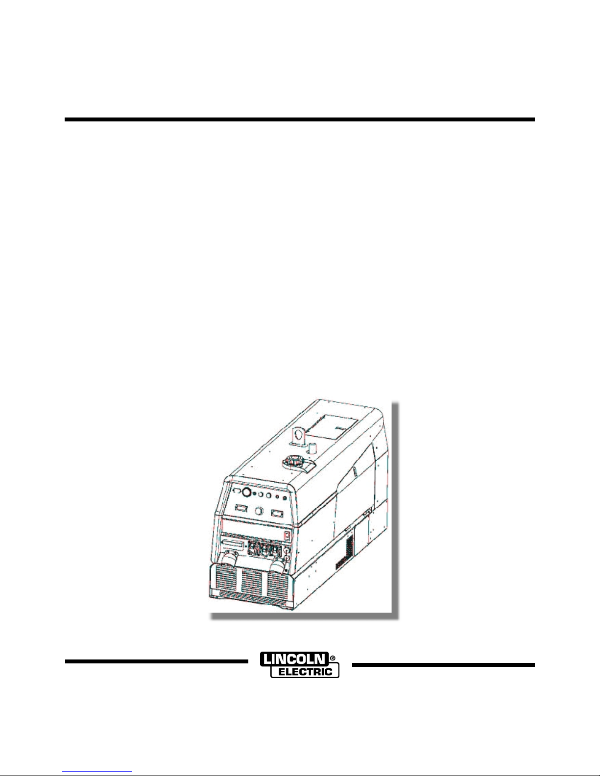
RANGER 305D CE
OPERATOR’S MANUAL
IM2024
10/2017
REV01
22801 St. Clair Ave., Cleveland Ohio 44117-1199 USA
English English
THE LINCOLN ELECTRIC COMPANY
www.lincolnelectric.eu
I

THE LINCOLN ELECTRIC COMPANY
EC DECLARATION OF CONFORMITY
Manufacturerandtechnical
documentationholder:
ECCompany:
Herebydeclarethatweldingequipment:
Productnumber:
IsinconformitywithCouncil
Directivesandamendments:
EN60974‐1:2012,Safetyrequirementsforarcweldingequipment,
Notifiedbody(for2000/14/EC
Conformity):
Guaranteedsoundpowerlevel:
Measuredsoundpowerlevel: LWA96dB(netpowerPel=
CEmarkingaffixedin‘15
SamirFarah,Manufacturer
ComplianceEngineeringManager
7September2017
MCD40e
TheLincolnElectricCompany
22801St.ClairAve.
ClevelandOhio44117‐1199USA
LincolnElectricEuropeS.L.
c/oBalmes,89‐802a
08008BarcelonaSPAIN
Ranger305DwithCEmarking
K2279(maycontainprefixes
andsuffixes)
MachineryDirective2006/42/EC;
LowVoltageDirective2014/35/EU
ElectromagneticCompatibility(EMC)Directive2014/30/EU
Noiseemissionintheenvironmentbyequipmentforuseoutdoors
2000/14/EC.
powersources;
EN60974‐10:2014,ArcWelding
Equipment‐Part10:Electromagnetic
compatibility(EMC)requirements;
ENISO3744:2010,Acoustics–Determinationofsoundpowerlevelsof
noisesourcesusingsoundpressure…reflectingplane;
EN60204‐1:2006,Safetyofmachinery–Electricalequipmentof
machines,Part1:Generalrequirements;
EN12100:2010,Safetyofmachinery–Generalprinciplesfordesign
assessmentandriskreduction.
LNE– Number:0071
ZAdeTrappes‐Élancourt
29,avenueRogerHennequin
78197TRAPPESCedex
LWA97dB(netpowerPel=7.5kW)
7.5 kW)
JacekStefaniak,EuropeanCommunityRepresentative
EuropeanProductManagerEquipment
8September2017
risk
English English
II
THANKS! For having chosen the QUALITY of the Lincoln Electric products.
Please Examine Package and Equipment for Damage. Claims for material damaged in shipment must be notified
immediately to the dealer.
For future reference record in the table below your equipment identification information. Model Name, Code &
Serial Number can be found on the machine rating plate.
Model Name:
………………...…………………………….…………………………………………………………………………………………..
Code & Serial number:
………………….……………………………………………….. …………………………………………………….……………..
Date & Where Purchased:
…………………………………………………………………... ……………………….…………………………………………..
ENGLISH INDEX
Technical Specifications ...................................................................................................................................................... 1
Electromagnetic Compatibility (EMC) ................................................................................................................................. 2
Safety .................................................................................................................................................................................. 3
Installation and Operator Instructions ................................................................................................................................. 4
Diagrams ........................................................................................................................................................................... 17
WEEE ................................................................................................................................................................................ 22
Spare Parts ....................................................................................................................................................................... 22
Authorized Service Shops Location .................................................................................................................................. 22
Electrical Schematic .......................................................................................................................................................... 22
12/05
English English
III
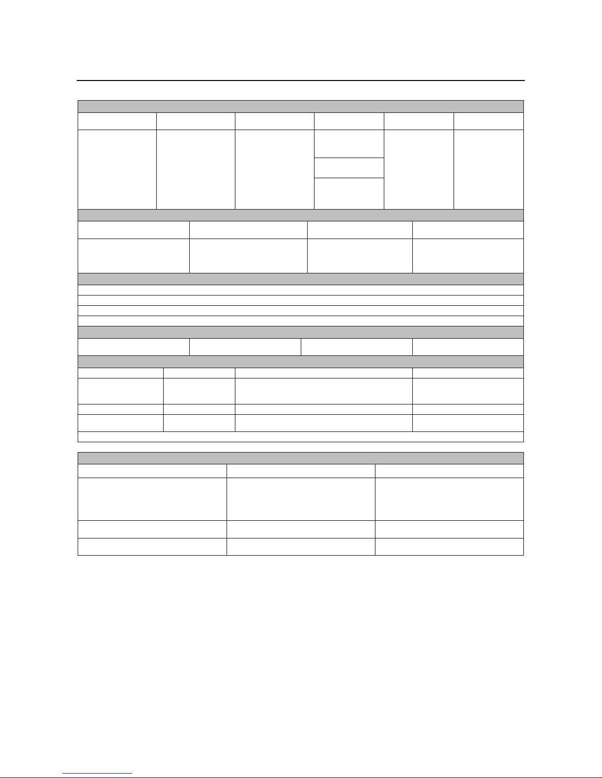
Technical Specifications
RANGER
®
305D (CE) (K2279-1, K2279-2, K2279-3)
INPUT – DIESEL ENGINE
Model Description Speed (RPM)
Displacement
(cu. cm)
Starting System Capacities
789
Bore x Stroke
(mm)
67x 68
12VDC Battery &
Starter
(Group 58: 550
cold crank amps)
Battery Charger
(3.6L)
Fuel: 45L
Oil: 3.2L
Radiator Coolant:
Kubota
D722
3 cylinder, 4 stroke
15.9 HP (12KW)
(3)
Net intermittent
3000 RPM
naturally aspirated
water cooled
High Idle 3100
Full Load 3000
Low Idle 2200
Diesel engine
RATED OUTPUT @ 40°C - WELDER
Welding Process
DC Constant Current
DC Pipe Current
Touch-Start
®
TIG
DC Constant Voltage
Welding Output
Current/Voltage/Duty Cycle
250A / 30V / 100%
250A / 30V / 100%
250A / 20V / 100%
250A / 27V / 100%
RATED OUTPUT @ 40°C - GENERATOR
Auxiliary Power
Output Range
20 to 305A
40 to 300A
20 to 250A
14 to 29V
(1)
8500 Watts Peak / 8000Watts Continuous, 50 Hz , 230V/400V, 3Phase
Sound Level
Sound Power: 97dB Lwa
Max. Weld OCV @
Rated Load RPM
60V
PHYSICAL DIMENSIONS
Height
909 mm
(2)
Width
546 mm
Length
1524 mm
Weight
341kg
ENGINE
Lubrication Emission Fuel System Governor
Full pressure with
full flow filter
Air Cleaner Engine Idler Muffler Engine Protection
Single element Automatic idler
ENGINE WARRANTY: 2 year complete (parts and labor) 3rd. year major components (parts and labor)
Certified to
EPA Tier 4
Compliant
Mechanical fuel pomp, Auto air bleed system
Electric shutoff solenoid indirect fuel injector.
Low noise muffler: made from long life, aluminized
steel.
Mechanical governor
Shutdown on low oil pressure &
engine temperature
(3)
DESCRIPTION
MODEL NUMBER K2279-1, K2279-3 (UK) K2279-2 (Europe)
400V (3 Ph) x 1
Receptacles
230V (1 Ph) x 1
115V x 1
(4)
14 Pin Connector
6 Pin Connector
Residual Current Device (RCD)
Circuit Breakers (Thermal/Magnetic)
(1
)
Output rating in watts is equivalent to volt-amperes at unity power factor. Output voltage is within ± 10% at all loads up to rated
capacity. When welding, available auxiliary power will be reduced.
(2)
To top of enclosure, add 152mm (6 “) to top of exhaust elbow.
(3)
Engine warranty may vary outside of the USA. (See Engine warranty for details)
(4)
Center-Tapped to ground.
4-pole, 25 Amp
(30mA trip current)
3 Phase, 20 Amp x 1
1 Phase, 15 Amp x 5
400V (3 Ph) x 1
230V (1 Ph) x 2
14 Pin Connector
6 Pin Connector
4-pole, 25 Amp
(30mA trip current)
3 Phase, 20 Amp x 1
1 Phase, 15 Amp x 4
3.6L
English English
1
Electromagnetic Compatibility (EMC)
This machine has been designed in accordance with all relevant directives and standards. However, it may still generate
electromagnetic disturbances that can affect other systems like telecommunications (telephone, radio, and television) or
other safety systems. These disturbances can cause safety problems in the affected systems. Read and understand
this section to eliminate or reduce the amount of electromagnetic disturbance generated by this machine.
system, it is responsibility of the installer or user of the equipment to ensure, by consultation with the distribution network
operator if necessary, that the equipment may be connected.
Before installing the machine, the operator must check the work area for any devices that may malfunction because of
electromagnetic disturbances. Consider the following.
Input and output cables, control cables, and telephone cables that are in or adjacent to the work area and the
Radio and/or television transmitters and receivers. Computers or computer controlled equipment.
Safety and control equipment for industrial processes. Equipment for calibration and measurement.
Personal medical devices like pacemakers and hearing aids.
Check the electromagnetic immunity for equipment operating in or near the work area. The operator must be sure
The dimensions of the work area to consider will depend on the construction of the area and other activities that are
Consider the following guidelines to reduce electromagnetic emissions from the machine.
Connect the machine to the input supply according to this manual. If disturbances occur if may be necessary to take
The output cables should be kept as short as possible and should be positioned together. If possible connect the
Shielding of cables in the work area can reduce electromagnetic emissions. This may be necessary for special
The Class A equipment is not intended for use in residential locations where the electrical power is provided by the public
low-voltage supply system. There can be potential difficulties in ensuring electromagnetic compatibility in those locations,
due to conducted as well as radio-frequency disturbances.
This machine has been designed to operate in an industrial area. The operator must install and operate this
equipment as described in this manual. If any electromagnetic disturbances are detected the operator must
put in place corrective actions to eliminate these disturbances with, if necessary, assistance from Lincoln
Electric. This equipment does not comply with IEC 61000-3-12. If it is connected to a public low-voltage
machine.
that all equipment in the area is compatible. This may require additional protection measures.
taking place.
additional precautions such as filtering the input supply.
work piece to ground in order to reduce the electromagnetic emissions. The operator must check that connecting
the work piece to ground does not cause problems or unsafe operating conditions for personnel and equipment.
applications.
WARNING
English English
2
Safety
03/09
WARNING
This equipment must be used by qualified personnel. Be sure that all installation, operation, maintenance and repair
procedures are performed only by qualified person. Read and understand this manual before operating this equipment.
Failure to follow the instructions in this manual could cause serious personal injury, loss of life, or damage to this
equipment. Read and understand the following explanations of the warning symbols. Lincoln Electric is not responsible
for damages caused by improper installation, improper care or abnormal operation.
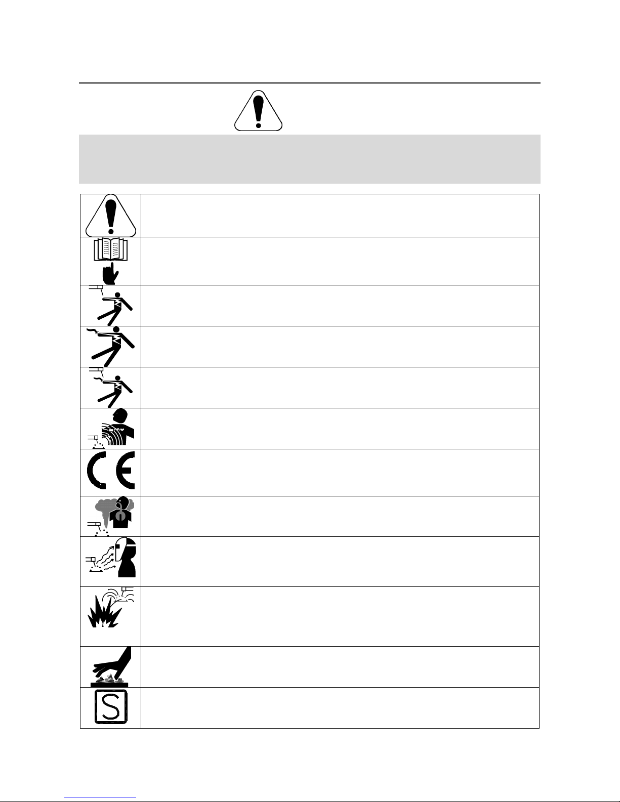
WARNING: This symbol indicates that instructions must be followed to avoid serious personal injury,
loss of life, or damage to this equipment. Protect yourself and others from possible serious injury or
death.
READ AND UNDERSTAND INSTRUCTIONS: Read and understand this manual before operating
this equipment. Arc welding can be hazardous. Failure to follow the instructions in this manual could
cause serious personal injury, loss of life, or damage to this equipment.
ELECTRIC SHOCK CAN KILL: Welding equipment generates high voltages. Do not touch the
electrode, work clamp, or connected work pieces when this equipment is on. Insulate yourself from
the electrode, work clamp, and connected work pieces.
ELECTRICALLY POWERED EQUIPMENT: Turn off input power using the disconnect switch at the
fuse box before working on this equipment. Ground this equipment in accordance with local electrical
regulations.
ELECTRICALLY POWERED EQUIPMENT: Regularly inspect the input, electrode, and work clamp
cables. If any insulation damage exists replace the cable immediately. Do not place the electrode
holder directly on the welding table or any other surface in contact with the work clamp to avoid the
risk of accidental arc ignition.
ELECTRIC AND MAGNETIC FIELDS MAY BE DANGEROUS: Electric current flowing through any
conductor creates electric and magnetic fields (EMF). EMF fields may interfere with some
pacemakers, and welders having a pacemaker shall consult their physician before operating this
equipment.
CE COMPLIANCE: This equipment complies with the European Community Directives.
FUMES AND GASES CAN BE DANGEROUS: Welding may produce fumes and gases hazardous to
health. Avoid breathing these fumes and gases. To avoid these dangers the operator must use
enough ventilation or exhaust to keep fumes and gases away from the breathing zone.
ARC RAYS CAN BURN: Use a shield with the proper filter and cover plates to protect your eyes from
sparks and the rays of the arc when welding or observing. Use suitable clothing made from durable
flame-resistant material to protect you skin and that of your helpers. Protect other nearby personnel
with suitable, non-flammable screening and warn them not to watch the arc nor expose themselves to
the arc.
WELDING SPARKS CAN CAUSE FIRE OR EXPLOSION: Remove fire hazards from the welding
area and have a fire extinguisher readily available. Welding sparks and hot materials from the welding
process can easily go through small cracks and openings to adjacent areas. Do not weld on any
tanks, drums, containers, or material until the proper steps have been taken to insure that no
flammable or toxic vapors will be present. Never operate this equipment when flammable gases,
vapors or liquid combustibles are present.
WELDED MATERIALS CAN BURN: Welding generates a large amount of heat. Hot surfaces and
materials in work area can cause serious burns. Use gloves and pliers when touching or moving
materials in the work area.
SAFETY MARK: This equipment is suitable for supplying power for welding operations carried out in
an environment with increased hazard of electric shock.
English English
3
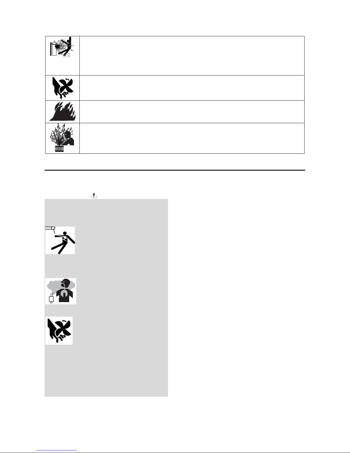
CYLINDER MAY EXPLODE IF DAMAGED: Use only compressed gas cylinders containing the
correct shielding gas for the process used and properly operating regulators designed for the gas and
pressure used. Always keep cylinders in an upright position securely chained to a fixed support. Do
not move or transport gas cylinders with the protection cap removed. Do not allow the electrode,
electrode holder, work clamp or any other electrically live part to touch a gas cylinder. Gas cylinders
must be located away from areas where they may be subjected to physical damage or the welding
process including sparks and heat sources.
MOVING PARTS can injure. Do not operate with doors open or guards off. Stop engine before
servicing. Keep away from moving parts. Keep all equipment safety guards, covers and devices in
position and in good repair. Keep hands, hair, clothing and tools away from V-belts, gears, fans and all
other moving parts when starting, operating or repairing equipment.
Do not add the fuel near an open flame welding arc or when the engine is running.
Stop the engine and allow it to cool before refueling to prevent spilled fuel from vaporizing on contact
with hot engine parts and igniting. Do not spill fuel when filling tank. If fuel is spilled, wipe it up and do
not start engine until fumes have been eliminated.
To avoid scalding, do not remove the radiator pressure cap when the engine is hot.
Installation and Operator Instructions
Read this entire section before installation or operation
of the machine.
Do not attempt to use this equipment until you have
thoroughly read the engine manufacturer
supplied with your welder. It includes important safety
precautions, detailed engine starting, operating and
maintenance instructions, and parts lists.
ELECTRIC SHOCK can kill:
Do not touch electrically live parts or electrode with
skin or wet clothing.
Insulate yourself from work and ground
Always wear dry insulating gloves.
ENGINE EXHAUST can kill:
Use in open, well ventilated areas or vent exhaust
outside.
MOVING PARTS can injure:
Do not operate with doors open or guards off.
Stop engine before servicing.
Keep away from moving parts
See additional warning information at front of this
operatorʼs manual.
Only qualified personnel should install, use, or service
this equipment.
WARNING
ʼs manual
General Description
The RANGER 305D (CE) is a diesel engine powered DC
multi-process welding power source and AC power
generator. The engine drives a generator that supplies
three-phase power for the DC welding circuit and threephase and single-phase power for the AC auxiliary
outlets. The DC welding control system uses state of
the art Chopper Technology (CT TM) for superior
welding performance.
Location and Ventilation
The welder should be located to provide an unrestricted
flow of clean, cool air to the cooling air inlets and to
avoid restricting the cooling air outlets. Also, locate the
welder so that the engine exhaust fumes are properly
vented to an outside area.
Stacking
RANGER 305D (CE) machines cannot be stacked.
Angle of Operation
Engines are designed to run in the level condition which
is where the optimum performance is achieved. The
maximum angle of continuous operation is 20 degrees in
all directions, 35 degrees Intermittent (less than 10
minutes continuous) in all directions. If the engine is to
be operated at an angle, provisions must be made for
checking and maintaining the oil level at the normal
(FULL) oil capacity in the crankcase.
When operating the welder at an angle, the effective fuel
capacity will be slightly less than the specified 45 liters
(12 gallons).
English English
4

Lifting
The machine weighs approximately 374 kg. (824 lbs)
with a full tank of fuel. A lift bail is mounted to the
machine and should always be used when lifting the
machine.
WARNING
Falling equipment can cause injury.
Lift only with equipment of adequate
lifting capacity.
Be sure machine is stable when lifting.
Do not lift this machine using lift bail if it is equipped
with a heavy accessory such as trailer or gas
cylinder.
Do not lift machine if lift bail is damaged.
Do not operate machine while suspended from lift
bail.
High Altitude Operation
At higher altitudes, output derating may be necessary.
For maximum rating, derate the machine 2.5% to 3.5%
for every 305m (1000ft.). Due to new EPA and other
local emissions regulations, modifications to the engine
for high altitude are restricted within the United States
and some European Countries. Use above 1828m
(6000 ft.) may be limited due to poor engine
performance or excessive exhaust smoke. An
authorized Kubota engine field service shop should be
contacted to deter-mine if any adjustments can be made
for operation in higher elevations locally.
High Temperature Operation
At temperatures above 40°C,welder output derating is
necessary. For maximum output ratings, derate the
welder output 2 volts for every 10°C above 40°C
Cold Weather Starting
With a fully charged battery and the proper oil, the
engine should start satisfactorily down to about -15°C. If
the engine must be frequently started at or below -5°C, it
may be desirable to install cold starting aides. The use
of No. 1D diesel fuel is recommended in place of No. 2D
at temperatures below -5°C. Allow the engine to warm
up before applying a load or switching to high idle.
WARNING
NOTE: Extreme cold weather starting may require
longer glow plug operation. Under no conditions should
ether or other starting fluids be used!
Towing
Check with distributor for the recommended trailer for
use with this equipment for road, in-plant and yard
towing by a vehicle. If the user adapts a non-Lincoln
trailer, he must assume responsibility that the method of
attachment and usage does not result in a safety hazard
nor damage the welding equipment. Some of the factors
to be considered are as follows:
Design capacity of trailer vs. weight of Lincoln
equipment and likely additional attachments.
Proper support of, and attachment to, the base of
the welding equipment so there will be no undue
stress to the framework.
Proper placement of the equipment on the trailer to
insure stability side to side and front to back when
being moved and when standing by itself while
being operated or serviced.
Typical conditions of use, i.e., travel speed;
roughness of surface on which the trailer will be
operated; environmental conditions; like
maintenance.
Conformance with laws in nation / region to be
used.
Vehicle Mounting
WARNING
Improperly mounted concentrated loads may cause
unstable vehicle handling and tires or other components
to fail.
Only transport this Equipment on serviceable
vehicles which are rated and designed for such
loads.
Distribute, balance and secure loads so vehicle is
stable under conditions of use.
Do not exceed maximum rated loads for
components such as suspension, axles and tires.
Mount equipment base to metal bed or frame of
vehicle.
Follow vehicle manufacturerʼs instructions.
Pre-Operation Engine Service
Read the engine operating and maintenance instructions
supplied with this machine.
WARNING
Stop engine and allow to cool before fueling.
Do not smoke when fueling.
Fill fuel tank at a moderate rate and do not overfill.
Wipe up spilled fuel and allow fumes to clear before
starting engine.
Keep sparks and flame away from tank.
Oil
The machine is shipped with the engine crankcase filled
with high quality SAE 10W-30 Oil that meets
classification CG-4 or CH-4 for diesel engines. Check
the oil level before starting the engine. If it is not up to
the full mark on the dip stick, add oil as required. Check
the oil level every four hours of running time during the
first 50 running hours. Refer to the engine Operator's
Manual for specific oil recommendations and break-in
information. The oil change interval is dependent on the
quality of the oil and the operating environment. Refer to
the Engine Operator's Manual for more details on the
proper service and maintenance intervals.
Fuel
Use Diesel fuel only.
WARNING
Fill the fuel tank with clean, fresh fuel. The capacity of
the tank is about 45 l.
WARNING
NOTE: A fuel shut off valve is located on the
prefilter/sediment filter. Which should be in the closed
position when the welder is not operated for extended
periods of time.
English English
5
 Loading...