

Lincoln Electric K1655-8, K1655-9, K1655-10, K1655-14, K1655-12 Operator's Manual
...
Operator’s Manual
Authorized Service and Distributor Locator:
www.lincolnelectric.com/locator
IM10344 | Issue D ate Apr-18
© Lincoln Global, Inc. All Rights Reserved.
For use with extraction arms having Product Numbers:
For Wall Mount:
K1655-8 - LF
A 3.1
(10FT) with Flange
K1655-9 - LF
A 4.1
(13FT) with Flange
K1655-10 - L
T
A 2.0
(6.5FT) Telescopic
K1655-14 - L
T
A 2.0-CW
(6.5FT) Telescopic
K1655-12 - LF
A 2.0
(6.5FT) with Flange
K1655-13 - LF
A 4.1-LC
(13FT) with Flange
For Mobiflex
®
:
K2633-5 - LF
A 3.1
(10FT)
K2633-6 - LF
A 3.1
(10FT) with Lamp Arc Sensor
K2633-7 - LF
A 4.1
(13FT)
K2633-8 - LF
A 4.1
(13FT) with Lamp Arc Sensor
Save for future reference
Date Purchased
Code: (ex: 10859)
Serial: (ex: U1060512345)
Fume Extraction Arms
THANK YOU FOR SELECTING
A QUALITY PRODUCT BY
LINCOLN ELEC TRIC.
PLEASE EXAMINE CARTON AND EQUIPMENT FOR
DAMAGE IMMEDIATELY
When this equipment is shipped, title passes to the purchaser
upon receipt by the carrier. Consequently, claims for material
damaged in shipment must be made by the purchaser against the
transportation company at the time the shipment is received.
SAFETY DEPENDS ON YOU
Lincoln arc welding and cutting equipment is designed and built
with safety in mind. However, your overall safety can be increased
by proper installation ... and thoughtful operation on your part.
DO NOT INSTALL, OPERATE OR REPAIR THIS EQUIPMENT
WITHOUT READING THIS MANUAL AND THE SAFETY
PRECAUTIONS CONTAINED THROUGHOUT. And, most importantly,
think before you act and be careful.
This statement appears where the information must be followed
exactly to avoid serious personal injury or loss of life.
This statement appears where the information must be followed
to avoid minor personal injury or damage to this equipment.
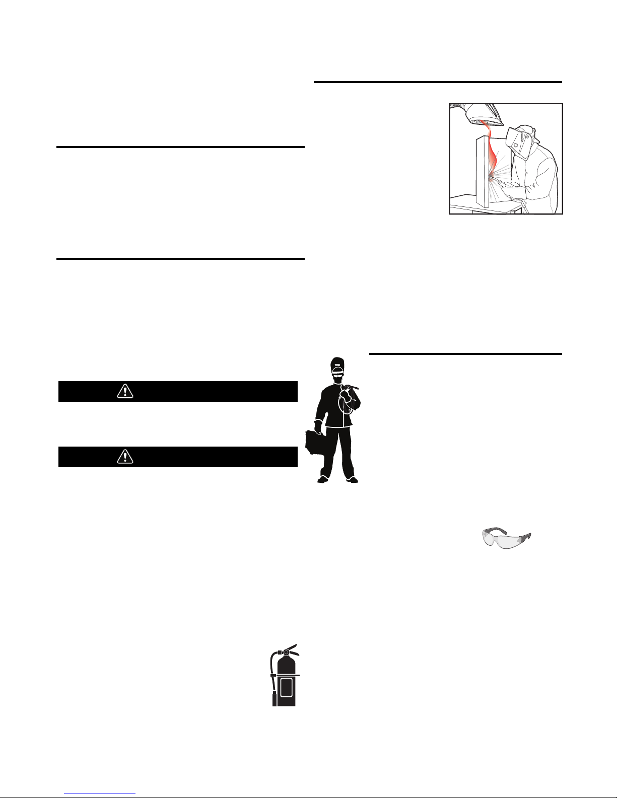
KEEP YOUR HEAD OUT OF THE FUMES.
DON’T get too close to the arc.
Use corrective lenses if necessary
to stay a reasonable distance
away from the arc.
READ and obey the Safety Data
Sheet (SDS) and the warning label
that appears on all containers of
welding materials.
USE ENOUGH VENTILATION or
exhaust at the arc, or both, to
keep the fumes and gases from
your breathing zone and the general area.
IN A LARGE ROOM OR OUTDOORS, natural ventilation may be
adequate if you keep your head out of the fumes (See below).
USE NATURAL DRAFTS or fans to keep the fumes away
from your face.
If you de velop unusual symptoms, see your supervisor.
Perhaps the welding atmosphere and ventilation system
should be checked.
WEAR CORRECT EYE, EAR &
BODY PROTECTION
PROTECT your eyes and face with welding helmet
properly fitted and with proper grade of filter plate
(See ANSI Z49.1).
PROTECT your body from welding spatter and arc
flash with protective clothing including woolen
clothing, flame-proof apron and gloves, leather
leggings, and high boots.
PROTECT others from splatter, flash, and glare
with protective screens or barriers.
IN SOME AREAS, protection from noise may be appropriate.
BE SURE protective equipment is in good condition.
Also, wear safety glasses in work area
AT ALL TIMES.
SPECIAL SITUATIONS
DO NOT WELD OR CUT containers or materials which previously
had been in contact with hazardous substances unless they are
properly cleaned. This is extremely dangerous.
DO NOT WELD OR CUT painted or plated parts unless special
precautions with ventilation have been taken. They can release
highly toxic fumes or gases.
Additional precautionary measures
PROTECT compressed gas cylinders from excessive heat,
mechanical shocks, and arcs; fasten cylinders so they cannot fall.
BE SURE cylinders are never grounded or part of an
electrical circuit.
REMOVE all potential fire hazards from welding area.
ALWAYS HAVE FIRE FIGHTING EQUIPMENT READY FOR
IMMEDIATE USE AND KNOW HOW TO USE IT.
WARNING
CAUTION
Safety 01 of 04 - 5/16/2018
SECTION A:
WARNINGS
CALIFORNIA PROPOSITION 65 WARNINGS
WARNING: Breathing diesel engine exhaust
exposes you to chemicals known to the State
of California to cause cancer and birth defects,
or other reproductive harm.
• Always start and operate the engine in a
well-ventilated area.
• If in an exposed area, vent the exhaust to the outside.
• Do not modify or tamper with the exhaust system.
• Do not idle the engine except as necessary.
For more information go to
www.P65 warnings.ca.gov/diesel
WARNING: This product, when used for welding or
cutting, produces fumes or gases which contain
chemicals known to the State of California to cause
birth defects and, in some cases, cancer. (California
Health & Safety Code § 25249.5 et seq.)
WARNING: Cancer and Reproductive Harm
www.P65warnings.ca.gov
ARC WELDING CAN BE HAZARDOUS. PROTECT
YOURSELF AND OTHERS FROM POSSIBLE SERIOUS
INJURY OR DEATH. KEEP CHILDREN AWAY.
PACEMAKER WEARERS SHOULD CONSULT WITH
THEIR DOCTOR BEFORE OPERATING.
Read and understand the following safety highlights. For
additional safety information, it is strongly recommended
that you purchase a copy of “Safety in Welding & Cutting ANSI Standard Z49.1” from the American Welding Society,
P.O. Box 351040, Miami, Florida 33135 or CSA Standard
W117.2-1974. A Free copy of “Arc Welding Safety” booklet
E205 is available from the Lincoln Electric Company,
22801 St. Clair Avenue, Cleveland, Ohio 44117-1199.
BE SURE THAT ALL INSTALLATION, OPERATION,
MAINTENANCE AND REPAIR PROCEDURES ARE
PERFORMED ONLY BY QUALIFIED INDIVIDUALS.
FOR ENGINE POWERED
EQUIPMENT.
1.a. Turn the engine off before troubleshooting
and maintenance work unless the
maintenance work requires it to be running.
1.b. Operate engines in open, well-ventilated areas or vent the engine
exhaust fumes outdoors.
1.c. Do not add the fuel near an open flame welding
arc or when the engine is running. Stop the
engine and allow it to cool before refueling to
prevent spilled fuel from vaporizing on contact
with hot engine parts and igniting. Do not spill fuel when filling
tank. If fuel is spilled, wipe it up and do not start engine until
fumes have been eliminated.
1.d. Keep all equipment safety guards, covers
and devices in position and in good repair.
Keep hands, hair, clothing and tools away
from V-belts, gears, fans and all other
moving parts when starting, operating or
repairing equipment.
1.e. In some cases it may be necessary to remove safety guards to
perform required maintenance. Remove guards only when
necessary and replace them when the maintenance requiring
their removal is complete. Always use the greatest care when
working near moving parts.
1.f. Do not put your hands near the engine fan. Do not attempt to
override the governor or idler by pushing on the throttle control
rods while the engine is running.
1.g. To prevent accidentally starting gasoline engines while turning
the engine or welding generator during maintenance work,
disconnect the spark plug wires, distributor cap or magneto wire
as appropriate.
1.h. To avoid scalding, do not remove the radiator
pressure cap when the engine is
hot.
ELECTRIC AND
MAGNETIC FIELDS MAY
BE DANGEROUS
2.a. Electric current flowing through any conductor
causes localized Electric and Magnetic Fields (EMF).
Welding current creates EMF fields around welding cables
and welding machines
2.b. EMF fields may interfere with some pacemakers, and
welders having a pacemaker should consult their physician
before welding.
2.c. Exposure to EMF fields in welding may have other health effects
which are now not known.
2.d. All welders should use the following procedures in order to
minimize exposure to EMF fields from the welding circuit:
2.d.1. Route the electrode and work cables together - Secure
them with tape when possible.
2.d.2. Never coil the electrode lead around your body.
2.d.3. Do not place your body between the electrode and work
cables. If the electrode cable is on your right side, the
work cable should also be on your right side.
2.d.4. Connect the work cable to the workpiece as close as possible to the area being welded.
2.d.5. Do not work next to welding power source.
SAFETY
Safety 02 of 04 - 5/16/2018
ELECTRIC SHOCK
CAN KILL.
3.a. The electrode and work (or ground) circuits are
electrically “hot” when the welder is on. Do
not touch these “hot” parts with your bare skin or wet clothing.
Wear dry, hole-free gloves to insulate hands.
3.b. Insulate yourself from work and ground using dry insulation.
Make certain the insulation is large enough to cover your full area
of physical contact with work and ground.
In addition to the normal safety precautions, if
welding must be performed under electrically
hazardous conditions (in damp locations or while
wearing wet clothing; on metal structures such as
floors, gratings or scaffolds; when in cramped
positions such as sitting, kneeling or lying, if there
is a high risk of unavoidable or accidental contact
with the workpiece or ground) use the following
equipment:
• Semiautomatic DC Constant Voltage (Wire) Welder.
• DC Manual (Stick) Welder.
• AC Welder with Reduced Voltage Control.
3.c. In semiautomatic or automatic wire welding, the electrode,
electrode reel, welding head, nozzle or semiautomatic welding
gun are also electrically “hot”.
3.d. Always be sure the work cable makes a good electrical
connection with the metal being welded. The connection should
be as close as possible to the area being welded.
3.e. Ground the work or metal to be welded to a good electrical (earth)
ground.
3.f. Maintain the electrode holder, work clamp, welding cable and
welding machine in good, safe operating condition. Replace
damaged insulation.
3.g. Never dip the electrode in water for cooling.
3.h. Never simultaneously touch electrically “hot” parts of electrode
holders connected to two welders because voltage
between the
two can be the total of the open circuit voltage of both
welders.
3.i. When working above floor level, use a safety belt to protect
yourself from a fall should you get a shock.
3.j. Also see It ems 6.c. and 8.
ARC RAYS CAN BURN.
4.a. Use a shield with the proper filter and cover plates to protect your
eyes from sparks and the rays of the arc when welding or
observing open arc welding. Headshield and filter lens should
conform to ANSI Z87. I standards.
4.b. Use suitable clothing made from durable flame-resistant material
to protect your skin and that of your helpers from the arc rays.
4.c. Protect other nearby personnel with suitable, non-flammable
screening and/or warn them not to watch the arc nor expose
themselves to the arc rays or to hot spatter or metal.
FUMES AND GASES
CAN BE DANGEROUS.
5.a. Welding may produce fumes and gases
hazardous to health. Avoid breathing these
fumes and gases. When welding, keep your head out of the fume.
Use enough ventilation and/or exhaust at the arc to keep fumes
and gases away from the breathing zone. When welding
hardfacing (see instructions on container or SDS)
or on lead or cadmium plated steel and other
metals or coatings which produce highly toxic
fumes, keep exposure as low as possible and
within applicable OSHA PEL and ACGIH TLV limits
using local exhaust or mechanical ventilation
unless exposure assessments indicate otherwise.
In confined spaces or in some circumstances,
outdoors, a respirator may also be required.
Additional precautions are also required when
welding
on galvanized steel.
5. b. The operation of welding fume control equipment is affected by
various factors including proper use and positioning of the
equipment, maintenance of the equipment and the specific
welding procedure and application involved. Worker exposure
level should be checked upon installation and periodically
thereafter to be certain it is within applicable OSHA PEL and
ACGIH TLV limits.
5.c. Do not weld in locations near chlorinated hydrocarbon vapors
coming from degreasing, cleaning or spraying operations. The
heat and rays of the arc can react with solvent vapors to form
phosgene, a highly toxic gas, and other irritating products.
5.d. Shielding gases used for arc welding can displace air and
cause
injury or death. Always use enough ventilation, especially in
confined areas, to insure breathing air is safe.
5.e. Read and understand the manufacturer’s instructions for this
equipment and the consumables to be used, including the
Safety Data Sheet (SDS) and follow your employer’s safety
practices. SDS forms are available from your welding
distributor or from the manufacturer.
5.f. Also see item 1.b.
SAFETY
Safety 03 of 04 - 5/16/2018
WELDING AND CUTTING
SPARKS CAN CAUSE
FIRE OR EXPLOSION.
6.a. Remove fire hazards from the welding area. If
this is not possible, cover them to prevent the welding sparks
from starting a fire. Remember that welding sparks and hot
materials from welding can easily go through small cracks and
openings to adjacent areas. Avoid welding near hydraulic lines.
Have a fire extinguisher readily available.
6.b. Where compressed gases are to be used at the job site, special
precautions should be used to prevent hazardous situations.
Refer to “Safety in Welding and Cutting” (ANSI Standard Z49.1)
and the operating information for the equipment being used.
6.c. When not welding, make certain no part of the electrode circuit is
touching the work or ground. Accidental contact can cause
overheating and create a fire hazard.
6.d. Do not heat, cut or weld tanks, drums or containers until the
proper steps have been taken to insure that such procedures
will not cause flammable or toxic vapors from substances inside.
They can cause an explosion even though they have been
“cleaned”. For information, purchase “Recommended Safe
Practices for the Preparation for Welding and Cutting of
Containers and Piping That Have Held Hazardous Substances”,
AWS F4.1 from the American Welding Society
(see address above).
6.e. Vent hollow castings or containers before heating, cutting or
welding. They may explode.
6.f. Sparks and spatter are thrown from the welding arc. Wear oil free
protective garments such as leather gloves, heavy shirt, cuffless
trousers, high shoes and a cap over your hair. Wear ear plugs
when welding out of position or in confined places. Always wear
safety glasses with side shields when in a welding area.
6.g. Connect the work cable to the work as close to the welding area
as practical. Work cables connected to the building framework or
other locations away from the welding area increase the
possibility of the welding current passing through lifting chains,
crane cables or other alternate circuits. This can create fire
hazards or overheat lifting chains or cables until they fail.
6.h. Also see item 1.c.
6.I. Read and follow NFPA 51B “Standard for Fire Prevention During
Welding, Cutting and Other Hot Work”, available from NFPA, 1
Batterymarch Park, PO box 9101, Quincy, MA 022690-9101.
6.j. Do not use a welding power source for pipe thawing.
CYLINDER MAY EXPLODE IF
DAMAGED.
7.a. Use only compressed gas cylinders containing
the correct shielding gas for the process used
and properly operating regulators designed for
the gas and pressure used. All hoses, fittings,
etc. should be suitable for the application and
maintained in good condition.
7.b. Always keep cylinders in an upright position securely chained to
an undercarriage or fixed support.
7.c. Cylinders should be located:
• Away from areas where they may be struck or subjected
to physical damage.
• A safe distance from arc welding or cutting operations
and any other source of heat, sparks, or flame.
7.d. Never allow the electrode, electrode holder or any other
electrically “hot” parts to touch a cylinder.
7.e. Keep your head and face away from the cylinder valve outlet
when opening the cylinder valve.
7.f. Valve protection caps should always be in place and hand tight
except when the cylinder is in use or connected for use.
7.g. Read and follow the instructions on compressed gas cylinders,
associated equipment, and CGA publication P-l, “Precautions for
Safe Handling of Compressed Gases in Cylinders,” available from
the Compressed Gas Association, 14501 George Carter Way
Chantilly, VA 20151.
FOR ELECTRICALLY
POWERED EQUIPMENT.
8.a. Turn off input power using the disconnect
switch at the fuse box before working on
the equipment.
8.b. Install equipment in accordance with the U.S. National Electrical
Code, all local codes and the manufacturer’s recommendations.
8.c. Ground the equipment in accordance with the U.S. National
Electrical Code and the manufacturer’s recommendations.
Refer to
http://www.lincolnelectric.com/safety
for additional safety information.
SAFETY
Safety 04 of 04 - 5/16/2018

2
SAFETY
FUME EXTRACTION ARMS
As a rule of thumb, for many mild steel electrode, if the air is visibly
clear and you are comfortable, then the ventilation is generally
adequate for your work. The most accurate way to determine if the
worker exposure does not exceed the applicable exposure limit for
compounds in the fumes and gases is to have an industrial hygienist
take and analyze a sample of the air you are breathing. This is
particularly important if you are welding with stainless, hardfacing or
Special Ventilation products. All Lincoln MSDS have a maximum fume
guideline number. If exposure to total fume is kept below that
number, exposure to all fume from the electrode (not coatings or
plating on the work) will be below the TLV.
There are steps that you can take to identify hazardous substances in
your welding environment. Read the product label and material safety
data sheet for the electrode posted in the work place or in the
electrode or flux container to see what fumes can be reasonably
expected from use of the product and to determine if special
ventilation is needed. Secondly, know what the base metal is and
determine if there is any paint, plating, or coating that could expose
you to toxic fumes and/or gases. Remove it from the metal being
welded, if possible. If you start to feel uncomfortable, dizzy or
nauseous, there is a possibility that you are being overexposed to
fumes and gases, or suffering from oxygen deficiency. Stop welding
and get some fresh air immediately. Notify your supervisor and coworkers so the situation can be corrected and other workers can
avoid the hazard. Be sure you are following these safe practices, the
consumable labeling and MSDS to improve the ventilation in your
area. Do not continue welding until the situation has been corrected.
NOTE: The MSDS for all Lincoln consumables is available on Lincoln’s web-
site: www.lincolnelectric.com
Before we turn to the methods available to control welding fume
exposure, you should understand a few basic terms:
Natural Ventilation is the movement of air through the
workplace caused by natural forces. Outside, this is usually
the wind. Inside, this may be the flow of air through open
windows and doors.
Mechanical Ventilation is the movement of air through the
workplace caused by an electrical device such as a portable
fan or permanently mounted fan in the ceiling or wall.
Source Extraction (Local Exhaust) is a mechanical device
used to capture welding fume at or near the arc and filter
contaminants out of the air.
The ventilation or exhaust needed for your application depends upon
many factors such as:
• Workspace volume
• Workspace configuration
• Number of welders
• Welding process and current
• Consumables used (mild steel, hardfacing, stainless, etc.)
• Allowable levels (TLV, PEL, etc.)
• Material welded (including paint or plating)
• Natural airflow
Your work area has adequate ventilation when there is enough
ventilation and/or exhaust to control worker exposure to hazardous
materials in the welding fumes and gases so the applicable limits for
those materials is not exceeded. See chart of TLV and PEL for Typical
Electrode Ingredients, the OSHA PEL (Permissible Exposure Limit), and
the recommended guideline, the ACGIH TLV (Threshold Limit Value),
for many compounds found in welding fume.
Ventilation
There are many methods which can be selected by the user to
provide adequate ventilation for the specific application. The following
section provides general information which may be helpful in
evaluating what type of ventilation equipment may be suitable for
your application. When ventilation equipment is installed, you should
confirm worker exposure is controlled within applicable OSHA PEL
and/or ACGIH TLV. According to OSHA regulations, when welding and
cutting (mild steels), natural ventilation is usually considered
sufficient to meet requirements, provided that:
1. The room or welding area contains at least 10,000 cubic feet
(about 22' x 22' x 22') for each welder.
2. The ceiling height is not less than 16 feet.
3. Cross ventilation is not blocked by partitions, equipment, or
other structural barriers.
4. Welding is not done in a confined space.
Spaces that do not meet these requirements should be equipped with
mechanical ventilating equipment that exhausts at least 2000 CFM of
air for each welder, except where local exhaust hoods or booths, or
air-line respirators are used.
Important Safety Note:
When welding with electrodes which require special
ventilation such as stainless or hardfacing (see
instructions on container or MSDS) or on lead or
cadmium plated steel and other metals or coatings which
produce hazardous fumes, keep exposure as low as
possible and below exposure limit values (PEL and TLV)
for materials in the fume using local exhaust or
mechanical ventilation. In con ned spaces or in some
circumstances, for example outdoors, a respirator may
be required if exposure cannot be controlled to the PEL
or TLV. (See MSDS and chart of TLV and PEL for Typical
Electrode Ingredients.) Additional precautions are also
required when welding on galvanized steel.
3
SAFETY
FUME EXTRACTION ARMS
BIBLIOGRAPHY AND SUGGESTED READING
ANSI Z87.1, Practice for Occupational and Educational Eye and Face
Protection, American National Standards Institute, 11 West 42nd
Street, New York, NY 10036.
Arc Welding and Your Health: A Handbook of Health Information for
Welding. Published by The American Industrial Hygiene Association,
2700 Prosperity Avenue, Suite 250, Fairfax, VA 22031-4319.
NFPA Standard 51B, Cutting and Welding Processes, National Fire
Protection Association, 1 Batterymarch Park, P.O. Box 9146, Quincy,
MA 02269-9959.
OSHA General Industry Standard 29 CFR 1910 Subpart Q. OSHA
Hazard Communication Standard 29 CFR 1910.1200. Available from
the Occupational Safety and Health Administration at
http://www.osha.org or contact your local OSHA office.
The following publications are published by The American Welding
Society, P.O. Box 351040, Miami, Florida 33135. AWS publications
may be purchased from the American Welding society at
http://www.aws.org or by contacting the AWS at 800-443-9353.
ANSI, Standard Z49.1, Safety in Welding, Cutting and Allied
Processes. Z49.1 is now available for download at no charge at
http://www.lincolnelectric.com/community/safety/ or at the AWS
website http://www.aws.org.
AWS F1.1, Method for Sampling Airborne Particulates Generated by
Welding and Allied Processes.
AWS F1.2, Laboratory Method for Measuring Fume Generation Rates
and Total Fume Emission of Welding and Allied Processes.
AWS F1.3, Evaluating Contaminants in the Welding Environment: A
Strategic Sampling Guide.
AWS F1.5, Methods for Sampling and Analyzing Gases from Welding
and Allied Processes.
AWS F3.2, Ventilation Guide for Welding Fume Control
AWS F4.1, Recommended Safe Practices for the Preparation for
Welding and Cutting of Containers and Piping That Have Held
Hazardous Substances.
AWS SHF, Safety and Health Facts Sheets. Available free of charge
from the AWS website at http://www.aws.org.
Supplemental Information:
(*) Not listed. Nuisance value maximum is 10 milligrams per cubic
meter. PEL value for iron oxide is 10 milligrams per cubic meter.
TLV value for iron oxide is 5 milligrams per cubic meter.
(**) As respirable dust.
(*****) Subject to the reporting requirements of Sections 311, 312,
and 313 of the Emergency Planning and Community Rightto-Know Act of 1986 and of 40CFR 370 and 372.
(b) The PEL for chromium (VI) is .005 milligrams per cubic meter as
an 8 hour time weighted average. The TLV for water-soluble
chromium (VI) is 0.05 milligrams per cubic meter. The TLV for
insoluble chromium (VI) is 0.01 milligrams per cubic meter.
(c) Values are for manganese fume. STEL (Short Term Exposure
Limit) is 3.0 milligrams per cubic meter. OSHA PEL is a ceiling
value.
(****) The TLV for soluble barium compounds is 0.5 mg/m
3
.
TLV and PEL values are as of October 2013. Always check Safety
Data Sheet (SDS) with product or on the Lincoln Electric website at
http://www.lincolnelectric.com
LISTED BELOW ARE SOME TYPICAL INGREDIENTS IN WELDING ELECTRODES AND
THEIR TLV (ACGIH) GUIDELINES AND PEL (OSHA) EXPOSURE LIMITS
INGREDIENTS CAS No. TLV mg/m3PEL mg/m
3
Aluminum and/or aluminum alloys (as AI)***** 7429-90-5 1.0 15
Aluminum oxide and/or Bauxite***** 1344-28-1 1. 0 5**
Barium compounds (as Ba)***** 513-77-9 0.5 0.5
Chromium and chromium alloys or compounds (as Cr)***** 7440-47-3 0.5(b) 0.5(b)
Hexavalent Chromium (Cr VI) 18540-29-9 0.05(b) .005(b)
Copper Fume 7440-50-8 0.2 0.1
Cobalt Compounds 7440-48-4 0.02 0.1
Fluorides (as F) 7789-75-5 2.5 2.5
Iron 7439-89-6 10* 10*
Limestone and/or calcium carbonate 1317-65-3 10* 15
Lithium compounds (as Li) 554-13-2 15 10*
Magnesite 1309-48-4 10 15
Magnesium and/or magnesium alloys and compounds (as Mg) 7439-95-4 10* 10*
Manganese and/or manganese alloys and compounds (as Mn)***** 7439-96-5 0.02 5.0(c)
Mineral silicates 1332-58-7 5** 5**
Molybdenum alloys (as Mo) 7439-98-7 10 10
Nickel***** 7440-02-0 0.1 1
Silicates and other binders 1344-09-8 10* 10*
Silicon and/or silicon alloys and compounds (as Si) 7440-21-3 10* 10*
Strontium compounds (as Sr) 1633-05-2 10* 10*
Zirconium alloys and compounds (as Zr) 12004-83-0 5 5

4
FUME EXTRACTION ARMS
TABLE OF CONTENTS
PAGE
GENERAL DESCRIPTION.............................................................................................................................................. 5
RECOMMENDED PROCESSES........................................................................................................................................5
PROCESS LIMITATIONS................................................................................................................................................. 5
EQUIPMENT LIMITATIONS............................................................................................................................................. 5
RECOMMENDED FILTER UNITS......................................................................................................................................5
DESIGN FEATURES........................................................................................................................................................5
TECHNICAL SPECIFICATIONS ................................................................................................................................. A-1
REACH ............................................................................................................................................................ A-2
PRESSURE DROP.......................................................................................................................................................A-3
INSTALLATION...........................................................................................................................................................A-4
SELECT SUITABLE LOCATION.....................................................................................................................................A-4
WALL MOUNTING LFA 3.1/4.1................................................................................................................................... A-5
MOBIFLEX MOUNTING LFA 3.1/4.1 ........................................................................................................................... A-8
WALL MOUNTING LTA 2.0-CW.................................................................................................................................A-11
WALL MOUNTING LTA 2.0 TELESCOPIC................................................................................................................... A-14
WALL MOUNTING LFA 2.0........................................................................................................................................A-16
WALL MOUNTING LFA 4.1-LC.................................................................................................................................. A-18
EXTENSION CRAMNES.............................................................................................................................................A-20
OPERATION ............................................................................................................................................................ B-1
GRAPHIC SYMBOLS THAT APPEAR ON THIS MACHINE OR IN THIS MANUAL............................................................... B-1
GENERAL DESCRIPTION.............................................................................................................................................B-1
MANUAL OPERATION.................................................................................................................................................B-1
USERS ............................................................................................................................................................ B-1
INTENDED USE.......................................................................................................................................................... B-1
PRODUCT COMBINATIONS.........................................................................................................................................B-2
CONTROLS ............................................................................................................................................................ B-2
OPTIONS/ACCESSORIES.......................................................................................................................................... C-1
MAINTENANCE.........................................................................................................................................................D-1
ROUTINE MAINTENANCE............................................................................................................................................D-1
PERIODIC MAINTENANCE...........................................................................................................................................D-2
SERVICE, MAINTENANCE AND REPAIRS..................................................................................................................... D-3
TROUBLESHOOTING................................................................................................................................................. E-1
PARTS LIST ............................................................................................................... PARTS.LINCOLNELECTRIC.COM
CONTENT/DETAILS MAY BE CHANGED OR UPDATED WITHOUT NOTICE. FOR MOST CURRENT INSTRUCTION MANUALS, GO
TO PARTS.LINCOLNELECTRIC.COM.
________________________________________________________________________

FUME EXTRACTION ARMS
General Description
The extraction arms have been specially designed for extracting
harmful fumes and gasses which are released during the most
common welding processes. Thanks to the patented construction
and the unique principle of the rotating of the hood the extraction
arm is easily maneuverable which enables constant adaptation of
the working reach to the specific requirements of the user.
LFA
Lincoln’s LFA extraction arms are spring-balanced for easy
positioning. They are intended for use with a low-vacuum, highvolume extraction fan. The LFA arms are commonly installed on a
Mobiflex
®
200-M or 400-MS mobile base unit with filter or with an
SF2400 Wall-Mounted Extraction Fan, with or without a Statiflex
®
200-M or 400-MS Wall-Mounted Filter Unit.
LTA
Lincoln’s LTA 2.0 fume extraction arms telescope 3-5 ft. long,
making them ideal for small workstation or booth applications.
They are intended for use with a low-vacuum, high-volume
extraction fan.
The telescopic arm is commonly installed with a SF2400 Wallmounted Fan. Extracted air can be vented outside through the Air
Exhaust Silencer, or filtered through a Statiflex 200-M or 400-MS
Wall-Mounted Filter Unit. The Starter/Overload Switch for the
SF2400 Extraction Fan protects the motor against overcurrent.
The optional Arc Sensor/LampKit for Wall-Mounted Systems
provides a work lamp and remote, hood-mounted switches for the
lamp and extraction fan, replacing the starter/overload switch.
recoMMenDeD processes
• GMAW
• FCAW
eQUipMent liMitations
• Never use the product for extracting inflammable, glowing or
burning particles or solid liquids.
• Never use the product for extracting aggressive fumes (such
as hydrochloric acid).
• Never use the product for extracting paint mists.
• Never use the product for extracting fumes containing alkaline
or acid.
NOTE: This list is not all inclusive.
recoMMenDeD filter Units
See Page A-1 for compatability
• Mobiflex 200, Mobiflex 200 HE
• Statiflex 200-M
DesiGn featUres
Standard:
• Ultra-easy positioning
• Minimal maintenance
• 360° rotatable hood
Optional:
• The Automatic Start/Stop Arc Sensor can be installed with the
Lamp Kit to turn the extraction fan on and off automatically
when it detects a welding arc flash.
• Extension Cranes are available in 7 ft. and 14 ft. lengths.
5
A-1
I
NSTALLATION
F
UME EXTRACTION ARMS
tecHnical specifications -
EXTRACTION ARM MOUNTING COMPATIBILITY
Product
N
umber
Description
M
obiflex - 50 Hz, 230V
K
2497-(2,4)
K
2497-(12,14)
M
obiflex - 60 Hz, 115V
K
1653-(2,3), K1741-(1,2)
K
1653-(4,5), K1741-(3,4)
Wall Mount
A
pplication
K1655-8 LFA 3.1 (10FT.) WITH FLANGE – – YES
K
1655-9LFA 4.1 (13FT.) WITH FLANGE
– – Y
ES
K1655-10 LTA 2.0 (6.5FT) TELESCOPIC – – YES
K1655-14 LTA 2.0-CW (6.5FT) TELESCOPIC – – YES
K1655-12 LFA 2.0 (6.5FT) – – YES
K1655-13 LFA 4.1-LC (13FT) – – YES
K2633-5 LFA 3.1 YES YES –
K2633-6 LFA 3.1 w/ LAS YES YES –
K2633-7 LFA 4.1 YES YES –
K2633-8 LFA 4.1 w/ LAS YES YES –
PHYSICAL DIMENSIONS
Product
Number
Net Weight Arm Length
Nominal Arm
Diameter
Extraction Capacity
Range
K1655-8 33 LBS. (15 KG) 10 FT. (3 M)
8 IN. (203 MM)
350-940 CFM
(600-1,600 M3/H)
K1655-9 37 LBS. (17 KG) 13 FT. (4 M)
K1655-10
15.4 LBS. (7 KG) 39.5 - 55 IN. (1000 - 1400 MM)
K1655-14
59.5 LBS (27KG) 60 - 98.4 IN. (1524 - 2500 MM)
K1655-12 33 LBS. (15 KG) 6.5 FT. (2 M)
K1655-13 33 LBS. (15 KG) 13 FT. (4 M)
K2633-5 32.8 LBS. (14.9 KG) 10 FT. (3 M)
K2633-6 37.3 LBS. (16.9 KG) 13 FT. (4 M)
K2633-7 33.5 LBS. (15.2 KG) 10 FT. (3 M)
K2633-8 38 LBS. (17.2 KG) 13 FT. (4 M)
AMBIENT CONDITIONS
Min. Temperature Max. Temperature Max. Rel. Humidity
41ºF (5ºC) 113ºF (45ºC) 80%
INSTALLATIONFUME EXTRACTION ARMS
#
16 ft
(4.9 m)
LFA 4.1
LFA 3.1
12 ft
(3.7 m)
12 ft
(3.7 m)
8 ft
(2.4 m)
4 ft
(1.2 m)
0 ft
(0 m)
16 ft
(4.9 m)
8 ft
(2.4 m)
4 ft
(1.2 m)
0 ft
(0 m)
79"
(2000 mm)
8"
(200 mm)
79"
(2000 mm)
79"
(2000 mm)
LFA 3.1, 130 in.
LFA 4.1, 170 in.
W
ith LFA 3.1, 287 in. (7300 mm)
With LFA 4.1, 327 in. (8300 mm)
79"
(2000 mm)
79"
(2000 mm)
8"
(200 mm)
79"
(2000 mm)
(3300/4300 mm)
LFA 3.1, 130 in.
LFA 4.1, 170 in.
(3300/4300 mm)
With LFA 3.1, 209 in. (5300 mm)
With LFA 4.1, 250 in. (6300 mm)
EC 4
EC 2
INSTALLATIONFUME EXTRACTION ARMS
##
Vacuum (inches WG) vs. Air Flow (CFM)
200
1
2
3
4
5
6
7
8
9
10
400 600
SF2400 Fan
LTA 2.0 &
LTA 2.0-CW
LFA 4.1 & Mobiex
LFA 4.1 LC
LFA 3.1 & Mobiex
14ft Crane with LFA 4.
1
7ft Crane with LFA 4.1
LFA 2.0
800 1000 1200
A-4
INSTALLATIONFUME EXTRACTION ARMS
Read this entire installation section before you
start installation.
INSTALLATION
ELECTRIC SHOCK CAN KILL.
• Only qualified personnel should perform
this installation.
• Turn the input power OFF and unplug
the machine from the receptacle before
working on this equipment.
• Insulate yourself from the work and ground.
• Always connect the machine to a power supply
grounded according to the National Electrical Code and
local codes.
MOVING PARTS can injure.
• Do not operate with covers open or
filter removed.
• Keep away from moving parts.
TIPPING Hazard
Unit is to be used on flat surface only.
The extraction arm must be fastened in an upright and
folded position during transport of the unit.
Only qualified personnel should install, use or
service this equipment.
select sUitable location
• Inspect the product and check it for damage. Verify the
functioning of the safety features.
• During use, always use Personal Protective Equipment (PPE)
to avoid injury. This also applies for persons who enter the
work area.
• Check the working environment. Do not allow unauthorized
persons to enter the working environment.
• Protect the product against water and humidity.
• Make sure the room is always sufficiently ventilated; this
applies especially to confined spaces.
The installer is responsible for following local
safety codes and regulations.
Before drilling, verify locations of existing gas, water, or
electrical conduits.
For mounting compatibility see “EXTRACTION
ARM MOUNTING COMPATIBILITY” table
located on page A-1.
For wall mounting applications:
Install wall mounting brackets as detailed in the section titled
“INSTALLATION OF WALL MOUNTING BRACKETS” for Operator
Manual IM10320 SF2400 Stationary Fan.
• LTA 2.0-CW includes mount assembly. See wall
mounting instruction on page A-11.
• FOR LAMP KIT APPLICATIONS:
Install the wiring for the lamp kit as detailed in the
section titled “Installing the Lamp Kit” for operator
manual IM10366 Lamp Kit for Wall Mounted Systems
For Mobiflex mounting applications:
Install the base swivel mount on top of the machine as detailed in
the section titled “INSTALLATION” for Operator Manual IM10335
Mobiflex 200 & 200 HE.
Tools and requirements
The following tools are needed to mount and maintain extraction
arms.
• 9/16” wrench and socket
• 1/2” wrench and socket
• 7/16” wrench and socket
• Oil lubricant
• Grease lubricant
• Utility knife
• PPE - safety glasses and gloves
• 1/8” hex bit
WARNING
WARNING
CAUTION
A-5
INSTALLATIONFUME EXTRACTION ARMS
WALL MOUNTING THE
LFA 3.1 (10FT.) OR
LFA 4.1 (13FT.) ARM
Components
*NOT SHOWN
See Parts Page for Hardware Bag Contents
For wall mounting applications:
Install wall mounting brackets as detailed in the section titled
“INSTALLATION OF WALL MOUNTING BRACKETS” for Operator
Manual IM10320 SF2400 Stationary Fan.
*NOT SHOWN
See Parts Page for Hardware Bag Contents
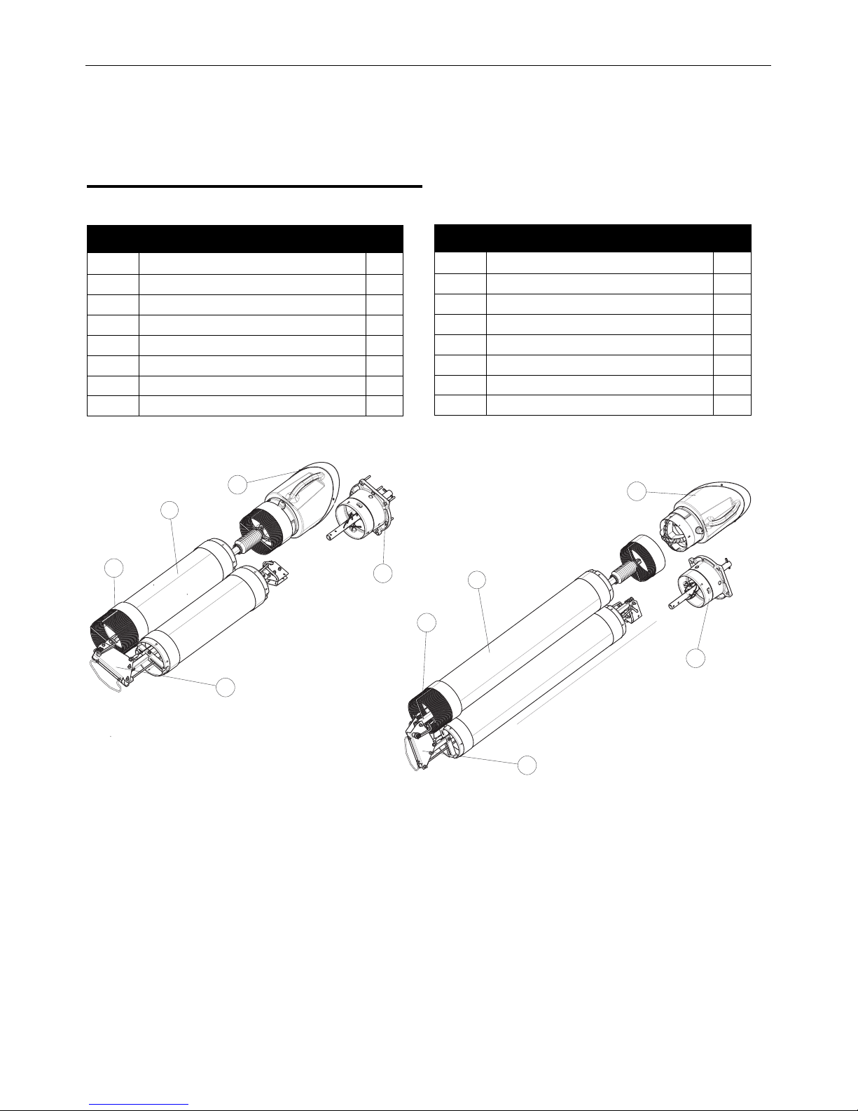
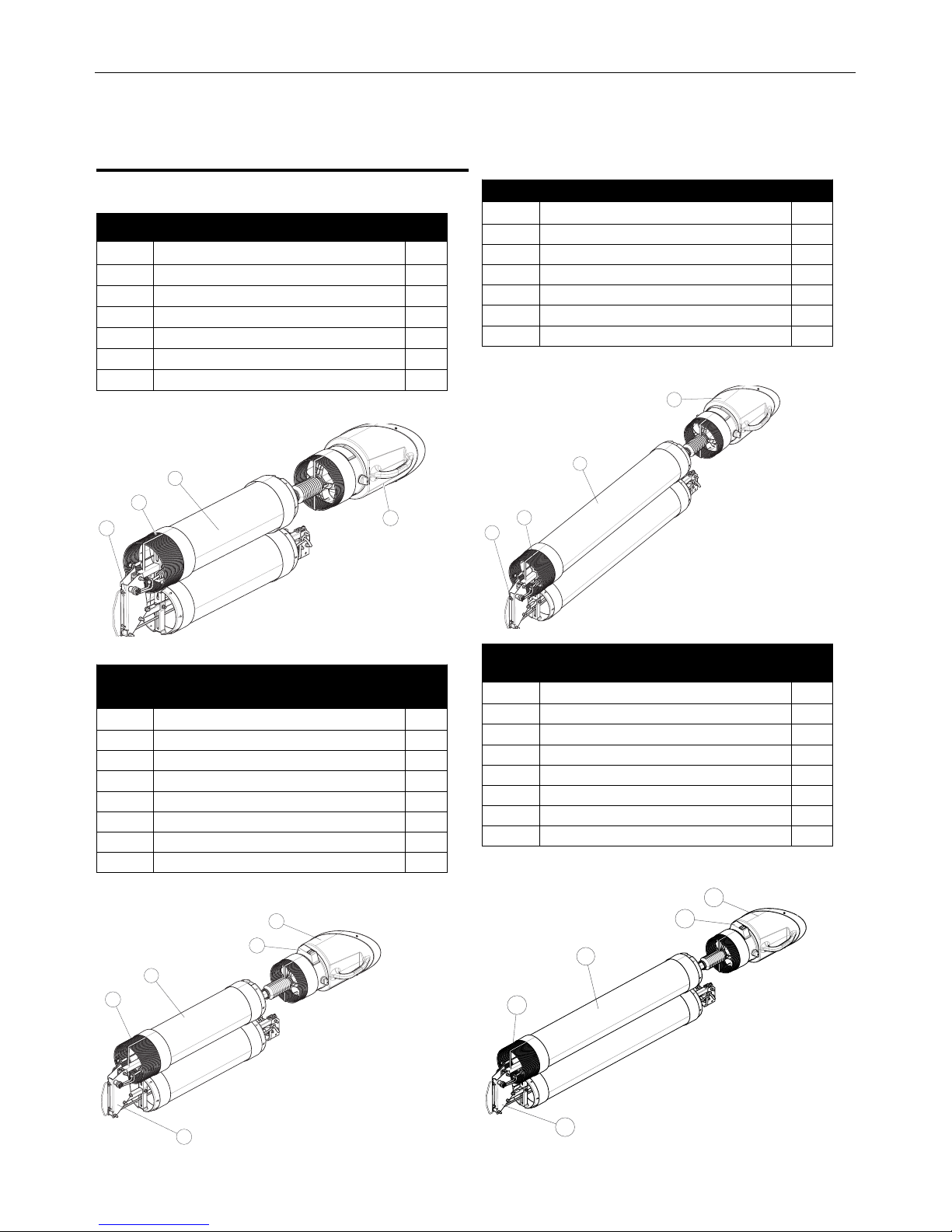
K1655-8 – LFA 3.1, 10FT EXTRACTION ARM
ITEM DESCRIPTION QTY
1 ARM BODY 1
2 HOSE SUPPORT 1
3 HOOD ASSEMBLY 1
4 FLEXIBLE HOSES 2
5 MOUNTING ASSEMBLY 1
6* INSTRUCTION MANUAL 1
7* LOOSE HARDWARE BAG 1
K1655-9 – LFA 4.1, 13FT EXTRACTION ARM
ITEM DESCRIPTION QTY
1 ARM BODY 1
2 HOSE SUPPORT 1
3 HOOD ASSEMBLY 1
4 FLEXIBLE HOSES 2
5 MOUNTING ASSEMBLY 1
6* INSTRUCTION MANUAL 1
7* LOOSE HARDWARE BAG 1
A-6
INSTALLATIONFUME EXTRACTION ARMS
MoUntinG tHe lfa 3.1 or 4.1 arM to tHe WallMoUntinG bracKet
See Figure A.1 for steps 1-4
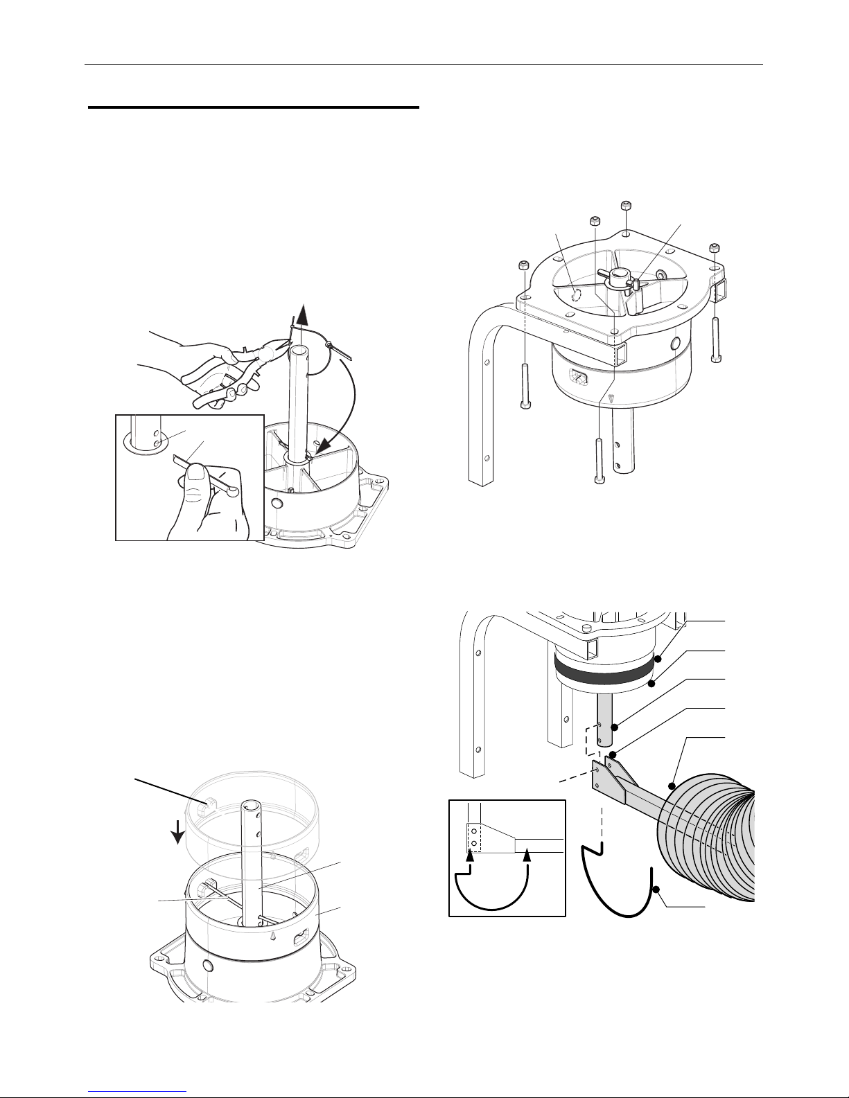
1. Cut through the upper cable tie to release the cotter pin
(Item A).
2. Lift the post of the base swivel mount by the lower cable tie.
3. Put the cotter pin through the lowest hole in the post (Item B)
and bend it around.
4. Cut the lower cable tie and let down the post.
FIGURE A.1
2. The mounting assembly of the arm comes in three pieces:
(See to Figure A.2)
• Metal rotating rod (Item A),
• red plastic ring (Item B),
• and metal spring collar pivot rod (Item C).
Mount the red plastic ring to the metal mounting assembly by
fitting the metal spring collarpivot rod through the hole in the
rotating rod, and snapping it into place on the U-shaped
indents on the red plastic ring. The lip of the ring should fit
securely against the top edge of the mounting assembly yet
rotate with the rod.
FIGURE A.2
3. Position the mounting assembly on a wall mounting bracket
(See Figure A.3) so that the cable hole (Figure A.3, Item A) is
on the wall side. Use the four 3” bolts and nuts to secure the
mounting assembly to the wall mounting bracket. Rotate the
hinge rod (Fig. 3, Item D) so the stop pin (Figure A.3, Item B)
is in the front.
FIGURE A.3
4. Mount the hanging adapter (Fig. A.4, Item D) to the hinge rod
using (2) 1.75” bolts with washers and nuts. Mount the spring
bracket (Fig. 5, Item F) into the two holes as shown. Position
one 8” rubber band (Fig. 5, Item A) and the flexible hose
supplied with the mounting bracket (Fig. 5, Item E) on the red
plastic ring of the rotating hinge.
FIGURE A.4
B
C
A
A
B
A
B
D
E
F
C
A
B
U-shaped
indent
5. Put another rubber band on the top of the arm. Use (2) 1.75”
bolts with nuts to mount the arm (Figure A.5, Item B) to the
hanging adapter (Figure A.5, Item A), using both mounting
holes as indicated.
FIGURE A.5
6. Remove the plastic and tape packaging from the arm
sections. Adjust the friction of the arm and hood movement
as described in the maintenance section of this manual.
When set, seal all hose connections with the arm seal bands.
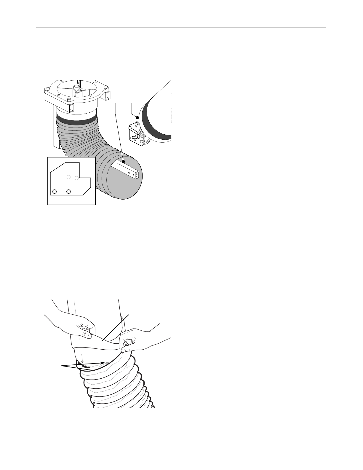
7. Fold back 2/3 of both arm seal bands. Remove the wrap of
the flexible hose. Place the flexible hose over both arm
sections. To secure the hose, at least one metal rings of the
hose should be applied over the ridges at each arm section.
Fold back the arm seal bands and place them over the hose.
The arm seal band should cover the arm section 0.5-1 in. See
Figure A.6
FIGURE A.6
AB
A-7
INSTALLATIONFUME EXTRACTION ARMS
Place at least
one metal band
of flexible hose
over ridge
Stretch arm band seal
over flexible tube
A-8
INSTALLATIONFUME EXTRACTION ARMS
MOBIFLEX MOUNTING
LFA 3.1 / 4.1 ARM
Components
*NOT SHOWN
See Parts Page for Hardware Bag Contents
*NOT SHOWN
See Parts Page for Hardware Bag Contents
For Mobiflex mounting applications:
Install the base swivel mount on top of the machine as detailed in
the section titled “INSTALLATION” for Operator Manual IM10335
Mobiflex 200 & 200 HE.
*NOT SHOWN
See Parts Page for Hardware Bag Contents
*NOT SHOWN
See Parts Page for Hardware Bag Contents
K2633-5 – LFA 3.1, 10FT EXTRACTION ARM
ITEM DESCRIPTION QTY
1 ARM BODY 1
2 HOSE SUPPORT 1
3 HOOD ASSEMBLY 1
4 FLEXIBLE HOSES 2
5* INSTRUCTION MANUAL 1
6* LOOSE HARDWARE BAG 1
K2633-6 – LFA 3.1, 10FT EXTRACTION ARM WITH
LAMP AND ARC SENSOR
ITEM DESCRIPTION QTY
1 ARM BODY 1
2 HOSE SUPPORT 1
3 HOOD ASSEMBLY 1
4 FLEXIBLE HOSES 2
5 LIGHT/POWER CONTROL SWITCH PANEL 1
6* INSTRUCTION MANUAL 1
7* LOOSE HARDWARE BAG 1
K2633-7 – LFA 4.1, 13FT EXTRACTION ARM
ITEM DESCRIPTION QTY
1 ARM BODY 1
2 HOSE SUPPORT 1
3 HOOD ASSEMBLY 1
4 FLEXIBLE HOSES 2
5* INSTRUCTION MANUAL 1
6* LOOSE HARDWARE BAG 1
K2633-8 – LFA 4.1, 13FT EXTRACTION ARM WITH
LAMP AND ARC SENSOR
ITEM DESCRIPTION QTY
1 ARM BODY 1
2 HOSE SUPPORT 1
3 HOOD ASSEMBLY 1
4 FLEXIBLE HOSES 2
5 LIGHT/POWER CONTROL SWITCH PANEL 1
6* INSTRUCTION MANUAL 1
7* LOOSE HARDWARE BAG 1
1
2
3
4
5
A-9
INSTALLATIONFUME EXTRACTION ARMS
MoUntinG tHe lfa 3.1 or 4.1 arM
to tHe MobifleX
See Figure A.7 for steps 1-4
1. Cut through the upper cable tie to release the cotter pin
(Item A).
2. Lift the post of the base swivel mount by the lower cable tie.
3. Put the cotter pin through the lowest hole in the post (Item B)
and bend it around.
4. Cut the lower cable tie and let down the post.
FIGURE A.7
5. Remove clamping pin from under arm seal band of the base
swivel mount.
6. Fold down the arm seal band and take off the red plastic ring.
See Figure A.8 for steps 7-8
7. Insert the clamping pin (Item A) through the hole in the post
located above the split pin.
8. Position the red plastic ring (Item B) and place the clamping
pin into the ridges (Item C). Rotating the red plastic ring may
be necessary.
FIGURE A.8
See Figure A.9 for steps 9-12
9. Turn the base swivel mount so, that the stop pin (A) is in line
with the cable lead-through hole (B).
FIGURE A.9
Note: The supply cable inside the base swivel mount of the
Mobiflex 200 OR 200 HE Base Unit is not used when mounting a
K2633-5 or K2633-7 LFA 3.1/4.1 Mobile Manual arm.
Do not remove the yellow tape attaching both arm sections.
See Figure A.10 for steps 1-3
1. Mount the extraction arm LFA 3.1/4.1 Mobile Manual (A) on
the post (B) using the two 5/16-18 bolts and two self-locking
5/16-18 nuts with washers.
2. Remove the yellow tape from both arm sections.
3. Proceed to Balance Check and adjust the friction of the arm
and hood movement as described in the maintenance section
of this manual.
FIGURE A.10
A
B
A
B
C
A
B
WARNING
B
A
A-10
INSTALLATIONFUME EXTRACTION ARMS
Electrical Connection for Lamp and Arc Sensor
The K2633-6 or K2633-8 LFA 3.1/4.1 Mobile Automatic extraction
arm contains an integrated Lamp & Arc Sensor Kit.
The supply cable inside the base swivel mount
should hang down vertically. Do not remove the
wire bridge.
See Figure A.11 for steps 4-7
4. Remove the wire bridge from the supply cable inside the base
swivel mount.
5. Connect the supply cables of the Mobiflex 200 or 200 HE Base
Unit and the extraction arm.
NOTE: If you are using an older Mobiflex 200-M with an older
connection on the supply side, use the supplied adapter cable
S31224-62 in the loose hardware kit.
6. Remove the yellow tape from both arm sections.
7. Turn the extraction arm 359° and check whether the supply
cable is long enough. If necessary, pull the supply cable of the
Mobiflex 200 or 200 HE Base Unit to a sufficient length.
FIGURE A.11
8. Remove the plastic and tape packaging from the arm
sections. Adjust the friction of the arm and hood movement
as described in the maintenance section of this manual.
When set, seal all hose connections with the arm seal bands.
9. Fold back 2/3 of both arm seal bands. Remove the wrap of
the flexible hose. Place the flexible hose over both arm
sections. To secure the hose, at least one metal rings of the
hose should be applied over the ridges at each arm section.
Fold back the arm seal bands and place them over the hose.
The arm seal band should cover the arm section 0.5-1 in. See
Figure A.12
FIGURE A.12
ATTENTION
0.5 - 1in. overlap
of arm band seal
on the arm
Place at least
one metal band
of flexible hose
over ridge
Stretch arm band seal
over flexible tube
WALL MOUNTING
LTA 2.0-CW ARM
Components
*NOT SHOWN
See Parts Page for Hardware Bag Contents
MoUntinG tHe lta 2.0-cW eXtraction arM on
tHe MoUnt asseMbly
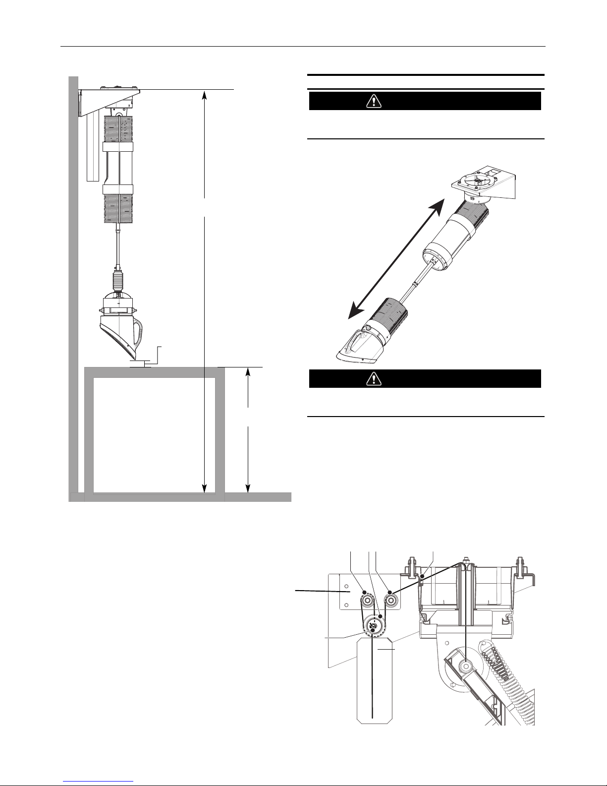
The recommended installation height of the wall mounting bracket
is 11.5 ft. (3500 mm). If the subject work bench is lower than the
standard height of 3.0 ft. (900 mm), it is advisable to install the
wall mounting bracket at a height of 9.8-10.6 ft. (3000-3250
mm). See Figures A.13 and A.14.
The package contains no mounting hardware for the Mount
Assembly since the required mounting hardware depends on the
wall type. The Mount Assembly can be mounted on:
• A thin brick or concrete wall (min. thickness of 4 inches/100
mm), using four threaded rods M10.
• A thick brick or concrete wall, using four cotter bolts
M10x120x60.
• Steel profile (e.g. H-profile), using four threaded rods M10.
NOTE: For central extraction systems, connec-
tion of the LTA 2.0-CW to an 8 inch duct
drop is made easier with K1657-5
Connector. See options/Accessories on
page C-1.
Mount the wall mounting bracket to the wall.
See Figure A.16 and A.17
FIGURE A.13
K1655-14 – LTA 2.0 – CW TELESCOPIC EXTRACTION
ARM
ITEM DESCRIPTION QTY
1 ARM BODY AND MOUNTING BRACKET 1
2 COUNTER WEIGHT 1
3 HOOD ASSEMBLY 1
4 FLEXIBLE HOSES 2
5 COUNTER WEIGHT GUIDE TUBE 1
6* INSTRUCTION MANUAL 1
7* LOOSE HARDWARE BAG 1
8.3 in
(210mm)
WALL FACING VIEW OF
MOUNT ASSEMBLY
0.5 in
(12mm)
4X
5.9 in
(150mm)
A-11
INSTALLATIONFUME EXTRACTION ARMS
30°
45°
G
E
C
B
A
D F
TOTAL HEIGHT
WORK BENCH
HEIGHT
MM INCH FEET
A 3500 138.8 11.5
B 900 35.4 3
C 450 17.7 1.5
D 1250 49.2 4.1
E 100 4.0 0.3
F 1800 70.9 5.9
G 800 31.5 2.6
A-12
INSTALLATIONFUME EXTRACTION ARMS
FIGURE A.14
ATTACHING THE ROPE
Tying the counterweight too low will affect the
reach of the extraction arm.
1. Pull the arm to the longest position (See Figure A.15).
FIGURE A.15
Failure to securely knot rope could
cause injury.
2. Guide the rope through the mounting assembly (D) and over
the pulley (C), the counterweight pulley (B) and the other
small pulley (A). (See Figure A.16)
3. Keep the counterweight in the highest position, which means
just below the small pulleys. Securely fasten the rope to the
counterweight by tying a knot (E) . The rope should be
threaded through the hole in the counterweight pulley. The
knot must be large enough so the rope cannot slip back
through the hole - take measures to make sure knot does
NOT untie itself. (See Figure A.16)
FIGURE A.16
11.5 ft. (3500mm)
0.3 ft.
(100mm)
3 ft. (900mm)
CAUTION
WARNING
A BC D
E
When tied
off properly,
there should
be about 18”
of extra rope
after the
knot, tie off
extra.
Bracket over pulleys
not shown for clarity in
routing of rope.
 Loading...