

Lincoln Electric K126-11 Innershield, K126-10 Innershield, K126-12 Innershield, K126-13 Innershield Operator's Manual
Page 1
Operator’s Manual
®
K126-[ ] Innershield
For use with machines having Code Numbers:
K126-10, K126-11, K126-12,
K126-13
IEC 60974-7
GB 15579.7: 22013
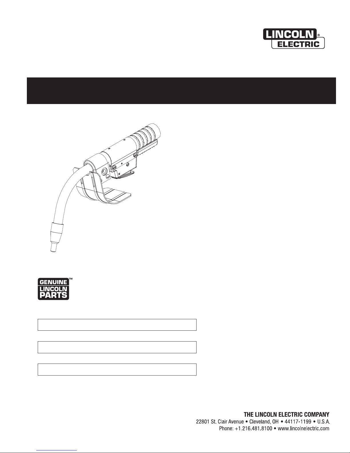
Pro Gun
Register your machine:
www.lincolnelectric.com/register
Authorized Service and Distributor Locator:
www.lincolnelectric.com/locator
Save for future reference
Date Purchased
Code: (ex: 10859)
Serial: (ex: U1060512345)
IM10045-B | Issue D ate Sept-12
© Lincoln Global, Inc. All Rights Reserved.
Page 2
THANK YOU FOR SELECTING
A QUALITY PRODUCT BY
LINCOLN ELEC TRIC.
PLEASE EXAMINE CARTON AND EQUIPMENT FOR
DAMAGE IMMEDIATELY
When this equipment is shipped, title passes to the purchaser
upon receipt by the carrier. Consequently, claims for material
damaged in shipment must be made by the purchaser against the
transportation company at the time the shipment is received.
SAFETY DEPENDS ON YOU
Lincoln arc welding and cutting equipment is designed and built
with safety in mind. However, your overall safety can be increased
by proper installation ... and thoughtful operation on your part.
DO NOT INSTALL, OPERATE OR REPAIR THIS EQUIPMENT
WITHOUT READING THIS MANUAL AND THE SAFETY
PRECAUTIONS CONTAINED THROUGHOUT. And, most importantly,
think before you act and be careful.
WARNING
This statement appears where the information must be followed
exactly to avoid serious personal injury or loss of life.
CAUTION
This statement appears where the information must be followed
to avoid minor personal injury or damage to this equipment.
KEEP YOUR HEAD OUT OF THE FUMES.
DON’T get too close to the arc.
se corrective lenses if necessary
U
to stay a reasonable distance
away from the arc.
READ and obey the Safety Data
Sheet (SDS) and the warning label
that appears on all containers of
welding materials.
USE ENOUGH VENTILATION or
exhaust at the arc, or both, to
keep the fumes and gases from
your breathing zone and the general area.
IN A LARGE ROOM OR OUTDOORS, natural ventilation may be
adequate if you keep your head out of the fumes (See below).
USE NATURAL DRAFTS or fans to keep the fumes away
from your face.
If you de velop unusual symptoms, see your supervisor.
Perhaps the welding atmosphere and ventilation system
should be checked.
WEAR CORRECT EYE, EAR &
BODY PROTECTION
PROTECT your eyes and face with welding helmet
properly fitted and with proper grade of filter plate
(See ANSI Z49.1).
PROTECT your body from welding spatter and arc
flash with protective clothing including woolen
clothing, flame-proof apron and gloves, leather
leggings, and high boots.
PROTECT others from splatter, flash, and glare
with protective screens or barriers.
IN SOME AREAS, protection from noise may be appropriate.
BE SURE protective equipment is in good condition.
Also, wear safety glasses in work area
AT ALL TIMES.
SPECIAL SITUATIONS
DO NOT WELD OR CUT containers or materials which previously
had been in contact with hazardous substances unless they are
properly cleaned. This is extremely dangerous.
DO NOT WELD OR CUT painted or plated parts unless special
precautions with ventilation have been taken. They can release
highly toxic fumes or gases.
Additional precautionary measures
PROTECT compressed gas cylinders from excessive heat,
mechanical shocks, and arcs; fasten cylinders so they cannot fall.
BE SURE cylinders are never grounded or part of an
electrical circuit.
REMOVE all potential fire hazards from welding area.
ALWAYS HAVE FIRE FIGHTING EQUIPMENT READY FOR
IMMEDIATE USE AND KNOW HOW TO USE IT.
Safety 01 of 04 - 06/15/2016
Page 3
SECTION A:
WARNINGS
CALIFORNIA PROPOSITION 65 WARNINGS
Diesel Engines
Diesel engine exhaust and some of its constituents are known
to the State of California to cause cancer, birth defects, and other
reproductive harm.
Gasoline Engines
The engine exhaust from this product contains chemicals known
to the State of California to cause cancer, birth defects, or other
reproductive harm.
ARC WELDING CAN BE HAZARDOUS. PROTECT
YOURSELF AND OTHERS FROM POSSIBLE SERIOUS
INJURY OR DEATH. KEEP CHILDREN AWAY.
PACEMAKER WEARERS SHOULD CONSULT WITH
THEIR DOCTOR BEFORE OPERATING.
Read and understand the following safety highlights. For
additional safety information, it is strongly recommended
that you purchase a copy of “Safety in Welding & Cutting ANSI Standard Z49.1” from the American Welding Society,
P.O. Box 351040, Miami, Florida 33135 or CSA Standard
W117.2-1974. A Free copy of “Arc Welding Safety” booklet
E205 is available from the Lincoln Electric Company,
22801 St. Clair Avenue, Cleveland, Ohio 44117-1199.
BE SURE THAT ALL INSTALLATION, OPERATION,
MAINTENANCE AND REPAIR PROCEDURES ARE
PERFORMED ONLY BY QUALIFIED INDIVIDUALS.
SAFETY
1.d. Keep all equipment safety guards, covers
and devices in position and in good repair.
Keep hands, hair, clothing and tools away
from V-belts, gears, fans and all other
moving parts when starting, operating or
repairing equipment.
1.e. In some cases it may be necessary to remove safety guards to
perform required maintenance. Remove guards only when
necessary and replace them when the maintenance requiring
heir removal is complete. Always use the greatest care when
t
working near moving parts.
1.f. Do not put your hands near the engine fan. Do not attempt to
override the governor or idler by pushing on the throttle control
rods while the engine is running.
1.g. To prevent accidentally starting gasoline engines while turning
the engine or welding generator during maintenance work,
disconnect the spark plug wires, distributor cap or magneto wire
as appropriate.
1.h. To avoid scalding, do not remove the radiator
pressure cap when the engine is
hot.
ELECTRIC AND
MAGNETIC FIELDS MAY
BE DANGEROUS
2.a. Electric current flowing through any conductor
causes localized Electric and Magnetic Fields (EMF).
Welding current creates EMF fields around welding cables
and welding machines
FOR ENGINE POWERED
EQUIPMENT.
1.a. Turn the engine off before troubleshooting
and maintenance work unless the
maintenance work requires it to be running.
1.b. Operate engines in open, well-ventilated
areas or vent the engine exhaust fumes outdoors.
1.c. Do not add the fuel near an open flame
welding arc or when the engine is running.
Stop the engine and allow it to cool before
refueling to prevent spilled fuel from
vaporizing on contact with hot engine parts
and igniting. Do not spill fuel when filling
tank. If fuel is spilled, wipe it up and do not start engine until
fumes have been eliminated.
2.b. EMF fields may interfere with some pacemakers, and
welders having a pacemaker should consult their physician
before welding.
2.c. Exposure to EMF fields in welding may have other health effects
which are now not known.
2.d. All welders should use the following procedures in order to
minimize exposure to EMF fields from the welding circuit:
2.d.1. Route the electrode and work cables together - Secure
them with tape when possible.
2.d.2. Never coil the electrode lead around your body.
2.d.3. Do not place your body between the electrode and work
cables. If the electrode cable is on your right side, the
work cable should also be on your right side.
2.d.4. Connect the work cable to the workpiece as close as possible to the area being welded.
2.d.5. Do not work next to welding power source.
Safety 02 of 04 - 06/15/2016
Page 4
SAFETY
ELECTRIC SHOCK
CAN KILL.
3.a. The electrode and work (or ground) circuits are
electrically “hot” when the welder is on. Do
not touch these “hot” parts with your bare skin or wet clothing.
Wear dry, hole-free gloves to insulate hands.
3.b. Insulate yourself from work and ground using dry insulation.
Make certain the insulation is large enough to cover your full area
f physical contact with work and ground.
o
In addition to the normal safety precautions, if
welding must be performed under electrically
hazardous conditions (in damp locations or while
wearing wet clothing; on metal structures such as
floors, gratings or scaffolds; when in cramped
positions such as sitting, kneeling or lying, if there
is a high risk of unavoidable or accidental contact
with the workpiece or ground) use the following
equipment:
• Semiautomatic DC Constant Voltage (Wire) Welder.
• DC Manual (Stick) Welder.
• AC Welder with Reduced Voltage Control.
3.c. In semiautomatic or automatic wire welding, the electrode,
electrode reel, welding head, nozzle or semiautomatic welding
gun are also electrically “hot”.
3.d. Always be sure the work cable makes a good electrical
connection with the metal being welded. The connection should
be as close as possible to the area being welded.
3.e. Ground the work or metal to be welded to a good electrical (earth)
ground.
3.f. Maintain the electrode holder, work clamp, welding cable and
welding machine in good, safe operating condition. Replace
damaged insulation.
3.g. Never dip the electrode in water for cooling.
3.h. Never simultaneously touch electrically “hot” parts of electrode
holders connected to two welders because voltage
two can be the total of the open circuit voltage of both
welders.
3.i. When working above floor level, use a safety belt to protect
yourself from a fall should you get a shock.
between the
ARC RAYS CAN BURN.
4.a. Use a shield with the proper filter and cover plates to protect your
eyes from sparks and the rays of the arc when welding or
observing open arc welding. Headshield and filter lens should
conform to ANSI Z87. I standards.
4.b. Use suitable clothing made from durable flame-resistant material
to protect your skin and that of your helpers from the arc rays.
4.c. Protect other nearby personnel with suitable, non-flammable
screening and/or warn them not to watch the arc nor expose
themselves to the arc rays or to hot spatter or metal.
FUMES AND GASES
CAN BE DANGEROUS.
5.a. Welding may produce fumes and gases
hazardous to health. Avoid breathing these fumes and gases.
When welding, keep your head out of the fume. Use enough
ventilation and/or exhaust at the arc to keep fumes and gases
away from the breathing zone. When welding hardfacing
(see instructions on container or SDS) or on lead
or cadmium plated steel and other metals or
coatings which produce highly toxic fumes, keep
exposure as low as possible and within applicable
OSHA PEL and ACGIH TLV limits using local
exhaust or mechanical ventilation unless exposure
assessments indicate otherwise. In confined
spaces or in some circumstances, outdoors, a
respirator may also be required. Additional
precautions are also required when welding
on galvanized steel.
5. b. The operation of welding fume control equipment is affected by
various factors including proper use and positioning of the
equipment, maintenance of the equipment and the specific
welding procedure and application involved. Worker exposure
level should be checked upon installation and periodically
thereafter to be certain it is within applicable OSHA PEL and
ACGIH TLV limits.
5.c. Do not weld in locations near chlorinated hydrocarbon vapors
coming from degreasing, cleaning or spraying operations. The
heat and rays of the arc can react with solvent vapors to form
phosgene, a highly toxic gas, and other irritating products.
3.j. Also see It ems 6.c. and 8.
5.d. Shielding gases used for arc welding can displace air and
cause
injury or death. Always use enough ventilation, especially in
confined areas, to insure breathing air is safe.
5.e. Read and understand the manufacturer’s instructions for this
equipment and the consumables to be used, including the
Safety Data Sheet (SDS) and follow your employer’s safety
practices. SDS forms are available from your welding
distributor or from the manufacturer.
5.f. Also see item 1.b.
Safety 03 of 04 - 06/15/2016
Page 5
SAFETY
WELDING AND CUTTING
SPARKS CAN CAUSE
FIRE OR EXPLOSION.
6.a. Remove fire hazards from the welding area. If
this is not possible, cover them to prevent the welding sparks
rom starting a fire. Remember that welding sparks and hot
f
materials from welding can easily go through small cracks and
openings to adjacent areas. Avoid welding near hydraulic lines.
Have a fire extinguisher readily available.
6.b. Where compressed gases are to be used at the job site, special
precautions should be used to prevent hazardous situations.
Refer to “Safety in Welding and Cutting” (ANSI Standard Z49.1)
and the operating information for the equipment being used.
6.c. When not welding, make certain no part of the electrode circuit is
touching the work or ground. Accidental contact can cause
overheating and create a fire hazard.
6.d. Do not heat, cut or weld tanks, drums or containers until the
proper steps have been taken to insure that such procedures
will not cause flammable or toxic vapors from substances inside.
They can cause an explosion even though they have been
“cleaned”. For information, purchase “Recommended Safe
Practices for the Preparation for Welding and Cutting of
Containers and Piping That Have Held Hazardous Substances”,
AWS F4.1 from the American Welding Society
(see address above).
6.e. Vent hollow castings or containers before heating, cutting or
welding. They may explode.
6.f. Sparks and spatter are thrown from the welding arc. Wear oil free
protective garments such as leather gloves, heavy shirt, cuffless
trousers, high shoes and a cap over your hair. Wear ear plugs
when welding out of position or in confined places. Always wear
safety glasses with side shields when in a welding area.
6.g. Connect the work cable to the work as close to the welding area
as practical. Work cables connected to the building framework or
other locations away from the welding area increase the
possibility of the welding current passing through lifting chains,
crane cables or other alternate circuits. This can create fire
hazards or overheat lifting chains or cables until they fail.
6.h. Also see item 1.c.
CYLINDER MAY EXPLODE IF
DAMAGED.
7.a. Use only compressed gas cylinders containing
the correct shielding gas for the process used
and properly operating regulators designed for
the gas and pressure used. All hoses, fittings,
tc. should be suitable for the application and
e
maintained in good condition.
7.b. Always keep cylinders in an upright position securely chained to
an undercarriage or fixed support.
7.c. Cylinders should be located:
• Away from areas where they may be struck or subjected
to physical damage.
• A safe distance from arc welding or cutting operations
and any other source of heat, sparks, or flame.
7.d. Never allow the electrode, electrode holder or any other
electrically “hot” parts to touch a cylinder.
7.e. Keep your head and face away from the cylinder valve outlet
when opening the cylinder valve.
7.f. Valve protection caps should always be in place and hand tight
except when the cylinder is in use or connected for use.
7.g. Read and follow the instructions on compressed gas cylinders,
associated equipment, and CGA publication P-l, “Precautions for
Safe Handling of Compressed Gases in Cylinders,” available from
the Compressed Gas Association, 14501 George Carter Way
Chantilly, VA 20151.
FOR ELECTRICALLY
POWERED EQUIPMENT.
8.a. Turn off input power using the disconnect
switch at the fuse box before working on
the equipment.
8.b. Install equipment in accordance with the U.S. National Electrical
Code, all local codes and the manufacturer’s recommendations.
6.I. Read and follow NFPA 51B “Standard for Fire Prevention During
Welding, Cutting and Other Hot Work”, available from NFPA, 1
Batterymarch Park, PO box 9101, Quincy, MA 022690-9101.
6.j. Do not use a welding power source for pipe thawing.
8.c. Ground the equipment in accordance with the U.S. National
Electrical Code and the manufacturer’s recommendations.
Refer to
http://www.lincolnelectric.com/safety
for additional safety information.
Safety 04 of 04 - 06/15/2016
Page 6

vivi
Page
Installation . . . . . . . . . . . . . . . . . . . . . . . . . . . . . . . . . . . . . . . . . . . . . . . . . . . . . . . . . . Section A
Specifications . . . . . . . . . . . . . . . . . . . . . . . . . . . . . . . . . . . . . . . . . . . . . . . . . . . . . . . . . . . . . . A-1
Wire Feeder Connector Kits. . . . . . . . . . . . . . . . . . . . . . . . . . . . . . . . . . . . . . . . . . . . . . . . . . . A-2
General DescriptIon . . . . . . . . . . . . . . . . . . . . . . . . . . . . . . . . . . . . . . . . . . . . . . . . . . . . . . . . A-3
Recommended Processes and Equipment. . . . . . . . . . . . . . . . . . . . . . . . . . . . . . . . . . . . A-3
Connection to Feeder with Ready to Weld Gun. . . . . . . . . . . . . . . . . . . . . . . . . . . . . . . . . . . . A-4
Conversion of K126-[ ] to weld with other Wire Feeders . . . . . . . . . . . . . . . . . . . . . . A-4 thru A-7
__________________________________________________________________________________________
Operation . . . . . . . . . . . . . . . . . . . . . . . . . . . . . . . . . . . . . . . . . . . . . . . . . . . . . . . . . . . Section B
Electrodes and Equipment . . . . . . . . . . . . . . . . . . . . . . . . . . . . . . . . . . . . . . . . . . . . . . . . B-1
Making a Weld . . . . . . . . . . . . . . . . . . . . . . . . . . . . . . . . . . . . . . . . . . . . . . . . . . . . . . . . . B-1
Avoiding Wire Feeding Problems . . . . . . . . . . . . . . . . . . . . . . . . . . . . . . . . . . . . . . . . . . . B-1
__________________________________________________________________________________________
Accessories. . . . . . . . . . . . . . . . . . . . . . . . . . . . . . . . . . . . . . . . . . . . . . . . . . . . . . . . . Section C
Wire Feeder Connection Kits . . . . . . . . . . . . . . . . . . . . . . . . . . . . . . . . . . . . . . . . . . . . . . . . . . C-1
Gun Consumable Parts . . . . . . . . . . . . . . . . . . . . . . . . . . . . . . . . . . . . . . . . . . . . . . . . . . . . . . C-2
__________________________________________________________________________________________
Maintenance . . . . . . . . . . . . . . . . . . . . . . . . . . . . . . . . . . . . . . . . . . . . . . . . . . . . . . . . Section D
Removal, Installation and Trimming Instructions for All Magnum® Liners . . . . . . . . . . . . D-1
Gun Tubes and Nozzles . . . . . . . . . . . . . . . . . . . . . . . . . . . . . . . . . . . . . . . . . . . . . . . . . . D-1
Cable Cleaning . . . . . . . . . . . . . . . . . . . . . . . . . . . . . . . . . . . . . . . . . . . . . . . . . . . . . D-1
__________________________________________________________________________________________
Troubleshooting . . . . . . . . . . . . . . . . . . . . . . . . . . . . . . . . . . . . . . . . . . . . . . . . . . . . . Section E
__________________________________________________________________________________________
Parts Lists . . . . . . . . . . . . . . . . . . . . . . . . . . . . . . . . . . . . . . . . . . . . . . . . . . . . . . . . . . P-103-AA
__________________________________________________________________________________________
Page 7

7
NOTES
7
K126-[ ] INNERSHIELD® PRO
Page 8
A-1
INSTALLATION
A-1
SPECIFICATIONS:
Duty Cycle
4
60%
80%
100%
Process
FCAW-SS
Model
K126-10
K126-11
K126-12
K126-13
Electrode Diameter Range
(0.8 – 2.4 mm)
K126-[ ] INNERSHIELD®PRO
K126 Innershield Pro Rated Output
0%
Welding Processes
Output Range (Amperes)
.035” – 3/32"
260A @ 100% duty cycle
350A @ 60% duty cycle
Physical Dimensions
Cable Length
10ft (3.0m)
15ft (4.5m)
Amperes
435
50
3
295
260
Wire Feed Speed Range
(See wire feeder
Instruction Manual)
Weight
7.3 lbs (3.3 kg)
11 lbs (5 kg)
Operating Temperature
Storage Temperature
Temperature Ranges
-4°F to 104°F (-20C to 40C)
-40°F to 185°F (-40C to 85C)
K126-[ ] INNERSHIELD® PRO
Page 9

A-2
Product
Number
INSTALLATION
TABLE A.1
Wire Feeder Connector Kits (up to 5/64” diameter wire)
Feeder Type
Power
Connector
Trigger Lead
Connector
Gas Tube and
Fitting
A-2
Connector Tools
K466-1
K466-2
K466-3
K466-4
K466-5
K466-6
K466-7
K466-8
K466-9
Lincoln
Except LN-8 or LN-9
using 1/16 and larger
electrodes
Tweco Adapted and
any -10 series feeder
Miller
Hobart 27
L-Tec
Adapted
Wirematic
Hobart
Series 2000
Lincoln LN-8 or LN-9
Using 1/16 and larger
electrode
SP100T and Related
Units
X
X
X
X
X
X
X
X
X
X
---
X
X
X
X
X
X
X
X
---
---
X
---
---
---
X
---
X
X
X
X
X
X
X
X
X
K466-10
Note: These kits must be used with the KP44-xx series cable liners.
Lincoln DH-10
X
TABLE A.2
X
Wire Feeder Connector Kits (3/32” diameter wire)
Product
Number
K613-2
K613-3
K613-6
K613-8
Note: These kits must be used with the KP45-xx series cable liners.
Feeder Type
Tweco #5 Adapted
Miller
Lincoln LN-8 or LN-9
Using 1/16 and larger
electrode
10 series feeder
with K1500-3 adapter
Power
Connector
X
X
X
X
Trigger Lead
Connector
---
X
X
X
---
Gas Tube and
Fitting
---
---
X
---
X
Connector Tools
X
X
X
X
K126-[ ] INNERSHIELD® PRO
Page 10

A-3
INSTALLATION
GENERAL DESCRIPTION
WARNING
• Do not touch electrically live parts
such as output terminals or internal
iring
w
------------------------------------------------------------------------
The K126 Innershield Pro gun and cable assemblies
have been designed specification for welding with mild
steel FCAW-S (self-shielded flux cored) processes.
The K126 Pro product is designed for extended life
and improved wire feeding in heavy duty welding
applications.
A-3
The K126 Innershield Pro has stainless steel jacketed
goosenecks for extended life. The goosenecks are
imilar in structure to a MIG gun gooseneck. A
s
copper tube is used for the conductor and a stainless
steel tube is used for the outer jacketing, while a
Teflon tube acts as an insulator between the copper
and steel. The replaceable spring liner extends
hrough the gooseneck, so that the wire is
t
continuously supported throughout the gun.
The K126 Innershield Pro gun utilizes a replaceable
connector assembly at the feeder end of the gun so
that the gun can be easily used with any feeder.
These connectors are the same K466/K613 kits used
with the Magnum MIG gun product line.
The K126 Innershield Pro products use a cable with a
core made from flat wound spring steel. The copper
conductors which transmit welding current are
wrapped around the spring core. Four #20 insulated
leads are wrapped along with the copper conductors
for use in the gun trigger circuit. The cable jacketing
is made from a cross linked polymer which provides
exceptional heat resistance and fatigue life.
A round wound spring steel liner is then placed inside
the spring core of the cable to contain the wire while it
is being transported to the welding arc. This liner is
replaceable so that it can be sized correctly for the
welding wire being used, and it can be removed and
replaced with a new liner as it wears out. Both of
these features improve the feeding of the wire through
the gun.
K126 INNERSHIELD PRO
350 AMPERES @ 60% DUTY CYCLE
RECOMMENDED PROCESSES AND
EQUIPMENT
RECOMMENDED PROCESSES
• FCAW-SS
PROCESS LIMITATIONS
• This gun can only be used with self-shielded wires.
The design will not support the use of shielding gas.
EQUIPMENT LIMITATIONS
• The K126 Pro will not operate with the LN23P
feeder.
• The K126 Pro does not support the 83% reduced
feed speed switch for pipe welding.
Description
Gun Feeder End
Product Cable Wire Size Contact Tips Tip Holder Insulator Cable Liner Gun Tube Connector
Number Length (m) in. (mm) Assembly
10 ft .072 (1.9) KP2745-072R
K126-10 (3.0) 3/32 (2.4) KP2745-332R KP2908-1 KP2907-1 KP45H-322-15 KP2906-62 K613-1
15 ft .072 (1.9) KP2745-072R
K126-11 (4.5) 3/32 (2.4) KP2745-332R KP2908-1 KP2907-1 KP45H-322-15 KP2906-62 K613-1
15 ft .072 (1.9) KP2745-072R
K126-12 (4.5) 5/64 (2.0) KP2745-564R KP2908-1 KP2907-1 KP44-564-15 KP2906-62 K466-1
15 ft .072 (1.9) KP2745-072R
K126-13 (4.5) 5/64 (2.0) KP2745-564R KP2908-1 KP2907-1 KP44-564-15 KP3267-1 K613-6
K126-[ ] INNERSHIELD® PRO
Page 11

A-4
Read this entire installation section before you
start installation.
AFETY PRECAUTIONS
S
INSTALLATION
WARNING
ELECTRIC SHOCK can kill.
• Do not touch electrically live parts
such as output terminals or
internal wiring.
• Insulate yourself from the work and
ground.
• Always wear dry insulating gloves.
------------------------------------------------------------------------
CONNECTION TO FEEDER WITH READY
TO WELD GUN
Connection to Adapted Feeders, Lincoln DH-10,
N-10, STT-10, and Power Feed 10 wire feeders
L
(5/64” or smaller diameter wire).
The K126-12 gun and cable assembly will connect
easily to any properly adapted feeder.
1. Check that the adapter and feeder outgoing
guide, as well as the drive roll, are appropriate
for the electrode size being used. On Lincoln
feeders, check that the K1500-2 gun adapter is
in place.
2. Fully push the brass connector end of the gun
cable into the brass adapter on the outgoing side
of the feeder wire drive. Secure the cable using
the hand screw or set screw in the adapter.
A-4
Connecting a K126-10 or K126-11 to a Lincoln
Feeder (5/64” or smaller diameter wire)
The K126-10 or K126-11 will connect to any wire
feeder with a Lincoln style gun receiver bushing (i.e.
LN-8, LN-9, LN-25 or any feeder with a K1500-1
bushing installed). (See Figure A.1)
1. Check that the drive roll(s) and feeder guide
tubes are appropriate for the electrode size
being used.
2. Fully push the brass connector end of the gun
cable into the conductor block on the outgoing
side of the feeder wire drive. Secure the cable
using the hand screw or set screw in the
conductor block.
3. Insert the round connector of the control cable
into the mating connector on the front of the
wire feeder.
FIGURE A.1
3. Insert the round connector of the control cable
into the mating connector on the front of the wire
feeder.
CONVERSION OF K126-10, K126-11, K12612 or K126-13 TO WELD WITH OTHER
WIRE FEEDERS
Prepare gun and determine correct connector kit
1. Determine which K466 or K613 kit is required for
your system using (Tables A.1 and A.2) in the
front part of the Installation Section.
2. Remove the insulator, tip holder and gun control
cable.
3. Lay gun and cable out straight on a flat surface.
4. Loosen set screw located in the brass cable
connector at the wire feeder end of the cable
using the 5/64 (2.0 mm) Allen wrench. Pull liner
out of cable.
5. Remove the brass cable connector from the
feeder end of the gun using the wrench provided.
6. Install the new connector kit using the
appropriate procedure which follows.
K466-3/K613-3 Installation (For Miller feeders)
1. Remove brass cable connector (see Figure A.2)
from the kit and screw it on to the feeder end of
the gun cable. Tighten the connection with the
wrench provided.
2. Attach the round connector of the gun control
cable provided to the trigger connector on the
front of the Miller feeder.
K126-[ ] INNERSHIELD® PRO
Page 12

A-5
GUN HANDLE
CABLE
SHIELD CLAMPING SCREWS
GUN TUBE
TIP HOLDER
TIP
INSULATOR
INSULATION TUBE
(K466-1 ONLY)
FEEDER END
CABLE HANDLE
BRASS CABLE
CONNECTOR
MOLDED GAS
PLUG
SET SCREW
LINER ASSEMBLY (LINER BUSHING TO BE SEATED
TIGHT AGAINST BRASS CABLE CONNECTOR
INSTALLATION
A-5
K466-4 Installation (For Hobart feeders; i.e. 27...)
1. Remove brass cable connector (see Figure A.2)
from the K466-4 kit and screw it on to the feeder
end of the gun cable. Tighten the connector
with the wrench provided.
2. Attach the phone plug connector of the gun
control cable provided to the trigger connector
on the front of the Hobart feeder.
K466-5 Installation (For L-Tec feeders equipped
with an L-Tec feeder connector assembly, MIG
35, MIG 31A, 225...)
1. Remove brass cable connector (see Figure A.2)
from the K466-5 kit and screw it onto the feeder
end of the gun cable. Tighten the connection
with the wrench provided.
2. For L-Tec machines that require trigger lead
connections to be made at a terminal strip
located within the machine (L-Tec 225), a gun
control cable with forked terminals is provided.
Connect the terminated leads to the terminal
strip. For a machine that requires a twist-lock
gun control cable connection, continue to use
the L-Tec gun control cable provided with the
L-Tec wire feeder connector assembly.
Connect the twist-lock plug to the proper
receptacle on the machine.
K466-6, K466-7, and K466-9 Installation
(Wirematic, Hobart Series 2000 Feeders, SP100T
ype and Power MIG)
T
1. Remove brass cable connector (see Figure A.2)
from the connector kit and screw it onto the feeder
end of the gun cable. Tighten the connection with
the wrench provided.
2. Attach the gun control cable provided to the trigger
connector on the wire feeder.
K613-2, K613-7 Installation (Tweco #5 compatible
feeders)
1. Remove brass cable connector from the kit and
screw it onto the feeder end of the gun cable.
Tighten the connection with the wrench
provided.
2. For K613-7, attach the round connector of the
gun control cable provided to the trigger
connector on the front of the Lincoln feeder.
K613-6 Installation (Lincoln Feeders, 3/32”
diameter wire)
1. Remove brass cable connector and insulation
tube from the kit. Slide the insulation tube onto
the connector from the threaded end and screw
it onto the feeder end of the gun cable. Tighten
the connection with the wrench provided.
FIGURE A.2
K126-[ ] INNERSHIELD® PRO
Page 13

A-6
2. Attach the round connector of the gun control
cable provided to the trigger connector on the
front of the Lincoln Feeder.
nstall and Trim the Cable Liner
I
Installation of (KP44 and KP45 series liners)
1. Lay the gun and cable out straight on a flat
surface.
2. Make sure that the set screw in the connector
end is backed out so as not to damage liner or
liner bushing. Remove and save the tip holder,
contact tip and insulator from the end of the gun
tube assembly.
3. Insert a new untrimmed liner into the connector
end of the cable. Be sure the liner bushing is
stenciled appropriately for the wire size being
used.
4. Be sure to fully seat the liner bushing in the
connector and:
INSTALLATION
A-6
CONNECT GUNS TO WIRE FEEDER
Connection to Miller Feeders
sing the Gun and cable assemblies which were
U
assembled with a K466-3 or K613-3 connection kit in
the beginning of this Installation Section will connect
easily to a variety of popular Miller wire feeders.
1. Check that the gun liner, connector cap liner,
and drive rolls are appropriate for the electrode
size being used.
2. Fully push the brass connector end of the gun
and cable into the connector receptacle on the
outgoing side of the feeder wire drive. Tighten
the hand screw to clamp down on the
connector.
3. Insert the control cable plug from the feeder
trigger circuit into the mating socket on the gun
cable feeder end handle.
For all connector kits except K466-3, K466-4 and
K613-3, tighten the set screw in the cable connector.
<OR>
For K466-3, K466-4 and K613-3, screw in the
connector cap provided in the kit until it seats on the
face of the bushing. Then insert the appropriate
piece of liner material into the connector cap and
tighten the set screw. Three pieces of liner material
are included in these connector kits to help guide the
electrode through the connector cap. The piece with
the smallest inner diameter is designed for .045" (1.2
mm) maximum diameter electrode and the other
liners fit the following wires (maximum size) in order
of increasing inside diameter: 1/16” (1.6 mm), 5/64”
(2.0 mm), 3/32” (2.4 mm) and 1/8” (3.2 mm).
NOTE: The maximum wire size for a K466-3 and
K466-4 is 5/64”. Therefore the 3/32” and
1/8” liners are not included with these
kits.
5. Be sure the cable is straight and then trim the
liner flush with the end of the gun tube.
6. Remove the gun tube and trim an additional
9/16” (12.7 mm) of material from the end of the
liner (a 9/16” gage is included on the wrench
supplied with the gun).
7. Replace the gun tube and tighten the clamping
screw to secure it.
8. Reassemble the tip holder, insulator, and
contact tip onto the end of the gun tube.
Connection to Hobart Feeders
Using the Gun and cable assemblies which were
assembled with a K466-4 connection kit in the
beginning of this Installation Section will connect
easily to a variety of Hobart wire feeders.
1. Check that the gun liner, connector cap liner,
and drive rolls are appropriate for the electrode
size being used.
2. Fully push the brass connector end of the gun
and cable into the connector receptacle on the
outgoing side of the feeder wire drive. Tighten
the hand screw to clamp down on the
connector.
3. Insert the control cable plug from the feeder
trigger circuit into the mating socket on the gun
cable feeder end handle.
Connection to L-Tec Adapted Feeders
Using the Gun and cable assemblies which were
assembled with a K466-5 connection kit in the
beginning of this Installation Section will connect
easily to an L-Tec feeder equipped with an L-Tec
feeder connector assembly.
1. Check that the adapter and feeder outgoing
guide as well as the drive roll, are appropriate
for the electrode size being used.
K126-[ ] INNERSHIELD® PRO
Page 14

A-7
INSTALLATION
A-7
2. Fully push the brass connector end of the gun
cable into the brass adapter on the outgoing
ide of the feeder wire drive. Secure the cable
s
using the hand screw, set screw, or pin.
3. Insert the control cable plug from the feeder
trigger circuit into the mating socket on the gun
able feeder end handle. For machines with a
c
twist-lock trigger lead receptacle, if the L-Tec
gun control cable does not easily connect with
the socket, the gun control cable that came with
the K466-5 kit can be used. To do this, cut off
the gun control leads as close to the forked
terminals as possible and skin back the leads
7/16" (11 mm). Remove the twist-lock plug from
the L-Tec control cable and connect it to the
K466-5 cable. Make sure the outer jacket of the
connector is caught within the plug's strain
relief.
Connection to Lincoln Wirematic, Power MIG,
Hobart Series 2000 Feeders, or SP100T Type
Feeders.
Gun cable assemblies which were assembled with a
K466-6, K466-7 or K466-9 Connection Kit in the
beginning of this Installation Section will connect
easily to a feeder.
Connection to a Lincoln feeder for 3/32” diameter
wire
1. Check that the drive roll(s) and feeder guide
tubes are appropriate for the electrode size
being used.
2. Fully push the brass connector end of the gun
cable into the conductor block on the outgoing
side of the feeder wire drive. Secure the cable
using the hand screw or set screw in the
conductor block.
3. Insert the round connector of the control cable
into the mating connector on the front of the
wire feeder.
1. Check that the adapter and feeder outgoing
guide, as well as the drive rolls, are appropriate
for the electrode size being used.
2. Fully push the brass connector end of the gun
cable into the outgoing side of the feeder wire
drive. Secure the cable using the hand screw
on the wire feeder.
3. Insert the control cable plug from the feeder
trigger circuit into the mating socket on the gun
cable feeder end handle.
Connection to a Tweco #5 adapted feeder.
1. Check that the drive roll(s) and feeder guide
tubes are appropriate for the electrode size
being used.
2. Fully push the brass connector end of the gun
cable into the conductor block on the outgoing
side of the feeder wire drive. Secure the cable
using the hand screw or set screw in the
conductor block.
3. Insert the round connector of the control cable
into the mating connector on the front of the
wire feeder.
K126-[ ] INNERSHIELD® PRO
Page 15

B-1
OPERATION
ELECTRODES AND EQUIPMENT
B-1
The K126 Innershield Pro gun has been designed for
se with Lincoln Innershield brand self-shielded cored
u
wire electrodes. Refer to the appropriate Lincoln
Process and Procedure Guidelines for the electrode
used for information on recommended electrical and
visible stick outs.
MAKING A WELD
WARNING
When using an open arc process, it is necessary
to use eye, head, and body protection.
ELECTRIC SHOCK can kill.
• Do not touch electrically live parts
such as output terminals or
internal wiring.
• Insulate yourself from the work and
ground.
• Always wear dry insulating gloves.
------------------------------------------------------------------------
1. Check that the welding power source is on.
2. Position electrode over joint. End of the electrode
should be slightly off the work.
3. Lower welding helmet, close gun trigger, and begin
welding. Hold the gun so the contact tip to work
distance gives the correct electrical stick out as
required for the procedure being used.
4. To stop welding, release the gun trigger and then
pull the gun away from the work after the arc goes
out.
AVOIDING WIRE FEEDING
PROBLEMS
Wire feeding problems can be avoided by observing the
following gun handling procedures:
1. Do not kink or pull cable around sharp corners.
2. Keep the electrode cable as straight as possible
when welding or loading electrode through cable.
3. Avoid wrapping excess cable around handle or
front of wire feeder.
FUMES AND GASES can be
dangerous.
• Keep your head out of fumes.
• Use ventilation or exhaust to
remove fumes from breathing zone.
-------------------------------------------------------
-----------------
WELDING SPARKS can cause fire or
explosion.
• Keep flammable material away.
------------------------------------------------------
------------------
ARCRAYS can burn.
• Wear eye, ear and body protection.
------------------------------------------------------------------------
Only qualified personnel should operate this
equipment.
4. Do not allow dolly wheels or trucks to run over
cables.
5. Keep cable clean by following maintenance instructions.
6. Use only clean, rust-free electrode. The Lincoln
electrodes have proper surface lubrication.
7. Replace contact tip when the arc starts to become
unstable or the contact tip end is fused or
deformed.
K126-[ ] INNERSHIELD® PRO
Page 16

C-1
WIRE FEEDER CONNECTION KITS
Wire Feeder Data Kit No. for Gun
Manufacturer
ACCESSORIES
Model
/64” diameter
5
or smaller wire
C-1
3/32” diameter
wire
Lincoln Electric
Tweco Adapted
Miller
Hobart
ESAB
LN-7, LN-8, & LN-9 series; LN-25 (0.052 max.); LN-742
LN-7, LN-8, & LN-9 series; LN-25 (1/16 and larger); LN-742
LF-72, LN-74
Series 10 feeders; LN-15; PF-10M; PF-15M
Power MIG & Wirematic series feeders
No. 2, 3, and 4 guns
No. 5 guns
Intellimatic, Side Kick, D-51A, Porta-MIG, Millermatic 130,
300 & 35 S-42GL, S-52A & S-54A
Swing Arc –Dual & Single, S-22, S-32S, 52D, 54D, 54E,
60 & 70 series
Dualmatic 27/70, H3S, H4S, H6S
Mega-Conds 27, 44, 45, 70, 70S
2000 series; 17 Hefty
Digamig, EH1, 5 & 11, SEH-4 & 5, SWM11 & 11B, 12, 13,
23, 24, 25, 26, 35, VAM2
K466-1
K466-8
K466-10
K466-10
K466-6
K466-2
K613-2
K466-3
K466-4
K466-7
K466-5
none
K613-6
none
none
none
none
K613-2
K613-3
K613-4
K613-5
none
K126-[ ] INNERSHIELD® PRO
Page 17

C-2
ACCESSORIES
GUN CONSUMABLE PARTS
LINER ASSEMBLY
Wire Diameter
Liner KP No.
C-2
0.035
0.045
0.052
1/16
0.068
0.072
5/64
3/32*
*K613-X Gun Connector Kit is Required for 3/32” wire.
CONTACT TIPS
Wire Diameter
0.035
0.045
0.052
1/16
0.068
0.072
5/64
3/32*
KP Number
10-piece pack
KP2745-035R
KP2745-045R
KP2745-052R
KP2745-116R
KP2745-072R
KP2745-072R
KP2745-564R
KP2745-332R
GUN TUBES
Stainless Steel Jacketed
Bend Angle
KP44-3545-15
KP44-3545-15
P44-116-15
K
KP44-116-15
KP44-564-15
KP44-564-15
KP44-564-15
KP45H-332-15*
KP Numbers
100-piece pack
KP2745-035R-B100
KP2745-045R-B100
KP2745-052R-B100
KP2745-116R-B100
KP2745-072R-B100
KP2745-072R-B100
KP2745-564R-B100
KP2745-332R-B100
Notes
KP2906-62
KP2906-62R
KP2906-30R
KP2906-30R-L
KP2906-30
KP2906-30-L
KP Number
KP2927-62R
KP2927-30R-L
KP3267-1
INSULATED GUIDES/THREAD PROTECTOR
62°
62°
30°
30°
30°
30°
Classic Varnished Jacketing
Bend Angle
62°
30°
30°
KP Number
KP2907-1
KP1987-1
KP1995-1
KP2090-1
KP Number
With reverse bend, extended length
No reverse bend, extended length
Desired ESO
1.5" or less
1.50" to 2.00"
2.00" to 2.75"
2.75" or greater
TIP HOLDERS
Notes
No reverse bend
With reverse bend
With reverse bend
No reverse bend
Notes
No reverse bend
With reverse bend
No reverse bend
KP2908-1
K126-[ ] INNERSHIELD® PRO
Magnum Pro Tip Holder
Page 18

D-1
GUN HANDLE
Liner
CABLE
TIP HOLDER
TIP
INSULATOR
FEEDER END
CABLE HANDLE
BRASS CABLE
CONNECTOR
SET SCREW
LINER ASSEMBLY (LINER BUSHING TO BE SEATED
TIGH T AGAINS T BRAS S CABLE CONNECTOR
L
I
N
E
R
T
R
I
M
L
E
N
G
T
H
9
/
1
6
"
(
1
4
.
3
m
m
)
MAINTENANCE
REMOVAL, INSTALLATION AND TRIMMING
INSTRUCTIONS FOR MAGNUM® LINERS
OTE: The variation in cable lengths prevents the inter-
N
changeability of liners. Once a liner has been cut for a particular gun, it should not be installed in another gun, unless
it can meet the liner cut off length requirement. Liners are
shipped with the jacket of the liner extended the proper
mount.
a
1. Remove the insulator and tip holder.
2. Lay the gun and cable straight on a flat surface.
For all connectors except K466-3, K466-4 and K613-3:
Loosen set screw located in the brass cable connector at
the wire feeder end of the cable using the same 5/64
(2.0 mm) Allen wrench. Pull liner out of cable.
<OR>
For K466-3, K466-4 and K613-3 connectors:
D-1
NOTE: The maximum wire size for a K466-3 and K466-4
is 5/64”. Therefore the 3/32” and 1/8” liners are not
included with these kits.
CAUTION
This screw should only be gently tightened.
Overtightening will split or collapse the liner and cause
poor wire feeding.
------------------------------------------------------------------------------
-
5. Be sure the cable is straight and then trim the liner
flush with the end of the gun tube.
6. Remove the gun tube and trim an additional 9/16”
(12.7 mm) of material from the end of the liner (a 9/16”
gage is included on the wrench supplied with the gun).
7. Replace the gun tube and tighten the clamping screw
to secure it.
8. Reassemble the tip holder, insulator, and contact tip
onto the end of the gun tube.
Remove the connector cap with the wrench provided.
Pull liner out of cable. If the liner is going to be replaced
with a different size liner, loosen set screw on the connector cap and remove piece of liner material.
3. Insert a new untrimmed liner into the connector end of
the cable. Be sure the liner bushing is stenciled
appropriately for the wire size being used.
4. Be sure to fully seat the liner bushing in the connector
and:
For all connector kits except K466-3, K466-4 and K613-
3, tighten the set screw in the cable connector.
<OR>
For K466-3, K466-4 and K613-3, screw in the connector
cap provided in the kit until it seats on the face of the
bushing. Then insert the appropriate piece of liner material into the connector cap and tighten the set screw.
Three pieces of liner material are included in these connector kits to help guide the electrode through the connector cap. The piece with the smallest inner diameter is
designed for .045" (1.2 mm) maximum diameter electrode and the other liners fit the following wires (maximum size) in order of increasing inside diameter: 1/16”
(1.6 mm), 5/64” (2.0 mm), 3/32” (2.4 mm) and 1/8” (3.2
mm).
Figure D.1
GUN TUBES AND NOZZLES
1. Replace worn contact tips as required.
2. Remove spatter from from contact tip, tip holder, insulator and gun tube after each 10 minutes of arc time or
as required.
3. To remove gun tube from gun, loosen socket-head
clamping screw in handle with 3/16" (4.8 mm) Allen
wrench.
4. Pull gun tube out from gun handle. To reinstall, insert
the gun tube, push in as far as possible, and retighten
clamping screw.
CABLE CLEANING
Clean cable liner after using approximately 150 (68 kg)
pounds of electrode. Remove the cable from the wire feeder and lay it out straight on the floor. Remove the contact tip
from the gun. Using an air hose and only partial pressure,
gently blow out the cable liner from the tip holder end.
CAUTION
• Excessive pressure at the start may cause the dirt to
form a plug.
-------------------------------------------------------------------------------
Flex the cable over its entire length and again blow out the
cable. Repeat this procedure until no further dirt comes out.
K126-[ ] INNERSHIELD® PRO
Page 19

E-1
TROUBLESHOOTING
HOW TO USE TROUBLESHOOTING GUIDE
WARNING
Service and Repair should only be performed by Lincoln Electric Factory Trained Personnel.
Unauthorized repairs performed on this equipment may result in danger to the technician and
machine operator and will invalidate your factory warranty. For your safety and to avoid
Electrical Shock, please observe all safety notes and precautions detailed throughout this
manual.
__________________________________________________________________________
This Troubleshooting Guide is provided to
help you locate and repair possible machine
malfunctions. Simply follow the three-step
procedure listed below.
E-1
Step 1. LOCATE PROBLEM (SYMPTOM).
Look under the column labeled “PROBLEM
(SYMPTOMS)”. This column describes
possible symptoms that the machine may
exhibit. Find the listing that best describes
the symptom that the machine is exhibiting.
Step 2. POSSIBLE CAUSE.
The second column labeled “POSSIBLE
CAUSE” lists the obvious external possibilities that may contribute to the machine
symptom.
Step 3. RECOMMENDED COURSE OF
ACTION
This column provides a course of action for
the Possible Cause, generally it states to
contact you local Lincoln Authorized Field
Service Facility.
If you do not understand or are unable to
perform the Recommended Course of
Action safely, contact you local Lincoln
Authorized Field Service Facility.
If for any reason you do not understand the test procedures or are unable to perform the tests/repairs safely, contact your
Local Lincoln Authorized Field Service Facility for technical troubleshooting assistance before you proceed.
CAUTION
K126-[ ] INNERSHIELD® PRO
Page 20

E-2
Observe all Safety Guidelines detailed throughout this manual
PROBLEMS
(SYMPTOMS)
TROUBLESHOOTING
POSSIBLE
CAUSE
E-2
RECOMMENDED
COURSE OF ACTION
No wire feed occurs when trigger is
pulled.
1. Machine is switched off or
unplugged.
2. Out of wire
3. Contact tip burnback.
4. Fully or partially blocked gun
liner.
5. Bird nest
6. Defective trigger (contacts open
or dirty).
7. Defective trigger circuit in gun.
8. No motor voltage or current from
machine.
9. Contact tip size too small for wire
diameter used.
1. Switch on or plug in machine.
2. Install full spool of specified wire.
3. Replace contact tip.
4. Remove and clean or replace gun
liner .
5. Cut out bird nest, reload wire, and
check for proper wire alignment.
6. Replace trigger assembly.
7. Disconnect gun from machine
and check trigger circuit for
continuity.
8. See Troubleshooting section in
welding machine’s or wire
feeder’s instruction manual.
9. Replace contact tip with one that
is the correct size.
Sluggish wire feed when trigger is
pulled.
1. Drive roll is worn or galled.
2. Mach i ne ’ s w i re fe e d s pe e d
setting is too low.
3. Wire is obstructed somewhere
along the wire feed path in the
gun.
4. Low motor voltage.
5. Gun cable is coiled/kinked.
6. Mechanical resistan ce to wire
feeding is too large
1. Clean drive roll or replace drive
roll.
2. Increase wire feed speed.
3. Check for obstructions: Remove
any wire shavings; remove kinked
wire; remove and clean or
replace gun liner.
4. See Troubleshooting section in
welding machine’s instruction
manual.
5. Remove all sharp curves from gun
cable while welding.
6. If using a reverse bend gun tube,
try welding with a non reverse
bend product.
CAUTION
If for any reason you do not understand the test procedures or are unable to perform the tests/repairs safely, contact your
Local Lincoln Authorized Field Service Facility for technical troubleshooting assistance before you proceed.
K126-[ ] INNERSHIELD® PRO
Page 21

E-3
Observe all Safety Guidelines detailed throughout this manual
PROBLEMS
(SYMPTOMS)
TROUBLESHOOTING
POSSIBLE
CAUSE
E-3
RECOMMENDED
COURSE OF ACTION
Intermittent wire feed when trigger
is pulled.
Frequent birdnesting or kinking of
wire in the gun cable.
Frequent occurrence of contact tip
burnback.
1. Drive roll has become galled.
2. Wire has become kinked along its
feed path.
1. Wire shav i ng s /l u br i ca n t is
building up in the cable.
2. Cable liner is too large for wire
size.
3. Mechanic al resistan ce to wire
feeding is too large.
1. Improper welding parameters or
technique (example: ESO is too
short).
1. Remo v e and then cle a n o r
replace drive roll.
2. Manually pull wire slowly thru gun
until unkinked wire emerges.
1. Clean cable or re p lac e cabl e
liner.
2. Install the smallest possible liner
which is specified for the wire
being used (i.e. use a .052-1/16
liner instead of a 1/16-5/64 liner
when welding with 1/16” diameter
wire.
3. If using a reverse bend gun tube,
try welding with a non reverse
bend product.
1. See welding wire literature for
proper settings.
Poor weld bead appearance.
Wire feeder runs or begins feeding
wire without pulling the gun trigger.
2. Wire ma y be fe ed i ng in te r mittently.
1. Improper electrode polarity.
2. Improper welding parameters or
technique.
1. Defective trigger (contacts closed
or dirty).
2. Defective (closed) trigger circuit
in the welding machine.
3. Trigger lead(s) inside gun cable
are shorted together or commonly
shor t ed t o e i th e r we l di n g or
accessory switch circuits.
2. See symptoms on intermittent or
sluggish wire feed.
1. Reconnect machine’s welding
output to proper electrode polarity.
2. Se e we lding wire liter ature for
proper settings.
1. Replace trigger assembly.
2. See mach i ne ’ s inst r uc t io n
manual.
3. Damaged control le a d s along
cabl e ; repa i r if possi b le .
Otherwise, replace gun cable.
If for any reason you do not understand the test procedures or are unable to perform the tests/repairs safely, contact your
Local Lincoln Authorized Field Service Facility for technical troubleshooting assistance before you proceed.
CAUTION
K126-[ ] INNERSHIELD® PRO
Page 22

WARNING
Spanish
AVISO DE
PRECAUCION
rench
F
ATTENTION
l Do not touch electrically live parts or
electrode with skin or wet clothing.
l Insulate yourself from work and
ground.
l
No toque las partes o los electrodos
bajo carga con la piel o ropa
mojada.
l
Aislese del trabajo y de la tierra.
l
Ne laissez ni la peau ni des
vêtements mouillés entrer en contact
avec des pièces sous tension.
l Isolez-vous du travail et de la terre.
l Keep flammable materials away.
l
Mantenga el material combustible
fuera del área de trabajo.
l Gardez à l’écart de tout matériel
inflammable.
l Wear eye, ear and body protection.
l
Protéjase los ojos, los oídos y el
cuerpo.
l Protégez vos yeux, vos oreilles et
votre corps.
German
WARNUNG
ortuguese
P
ATENÇÃO
Japanese
Chinese
Korean
Arabic
l
Berühren Sie keine stromführenden
Teile oder Elektroden mit Ihrem
Körper oder feuchter Kleidung!
l Isolieren Sie sich von den
Elektroden und dem Erdboden!
l Não toque partes elétricas e
electrodos com a pele ou roupa
molhada.
l Isole-se da peça e terra.
l Entfernen Sie brennbarres Material!
l Mantenha inflamáveis bem
guardados.
l Tragen Sie Augen-, Ohren- und Kör-
perschutz!
l Use proteção para a vista, ouvido e
corpo.
READ AND UNDERSTAND THE MANUFACTURER’S INSTRUCTION FOR THIS EQUIPMENT AND THE CONSUMABLES TO BE
USED AND FOLLOW YOUR EMPLOYER’S SAFETY PRACTICES.
SE RECOMIENDA LEER Y ENTENDER LAS INSTRUCCIONES DEL FABRICANTE PARA EL USO DE ESTE EQUIPO Y LOS
CONSUMIBLES QUE VA A UTILIZAR, SIGA LAS MEDIDAS DE SEGURIDAD DE SU SUPERVISOR.
LISEZ ET COMPRENEZ LES INSTRUCTIONS DU FABRICANT EN CE QUI REGARDE CET EQUIPMENT ET LES PRODUITS A
ETRE EMPLOYES ET SUIVEZ LES PROCEDURES DE SECURITE DE VOTRE EMPLOYEUR.
LESEN SIE UND BEFOLGEN SIE DIE BETRIEBSANLEITUNG DER ANLAGE UND DEN ELEKTRODENEINSATZ DES
HERSTELLERS. DIE UNFALLVERHÜTUNGSVORSCHRIFTEN DES ARBEITGEBERS SIND EBENFALLS ZU BEACHTEN.
Page 23

l Keep your head out of fumes.
l Use ventilation or exhaust to
remove fumes from breathing zone.
l
Los humos fuera de la zona de
respiración.
l
Mantenga la cabeza fuera de los
humos. Utilice ventilación o
aspiración para gases.
l
Gardez la tête à l’écart des fumées.
l
Utilisez un ventilateur ou un
aspirateur pour ôter les fumées des
zones de travail.
l
Vermeiden Sie das Einatmen von
Schweibrauch!
l
Sorgen Sie für gute Be- und
Entlüftung des Arbeitsplatzes!
l
Mantenha seu rosto da fumaça.
l
Use ventilação e exhaustão para
remover fumo da zona respiratória.
l Turn power off before servicing.
l
Desconectar el cable de
alimentación de poder de la
máquina antes de iniciar cualquier
servicio.
l
Débranchez le courant avant
l’entretien.
l
Strom vor Wartungsarbeiten
abschalten! (Netzstrom völlig
öffnen; Maschine anhalten!)
l Não opere com as tampas removidas.
l Desligue a corrente antes de fazer
serviço.
l Não toque as partes elétricas nuas.
l Do not operate with panel open or
guards off.
l
No operar con panel abierto o
guardas quitadas.
l
N’opérez pas avec les panneaux
ouverts ou avec les dispositifs de
protection enlevés.
l Anlage nie ohne Schutzgehäuse
oder Innenschutzverkleidung in
Betrieb setzen!
l
Mantenha-se afastado das partes
moventes.
l
Não opere com os paineis abertos
ou guardas removidas.
WARNING
panish
S
AVISO DE
PRECAUCION
French
ATTENTION
erman
G
WARNUNG
ortuguese
P
ATENÇÃO
Japanese
Chinese
Korean
Arabic
LEIA E COMPREENDA AS INSTRUÇÕES DO FABRICANTE PARA ESTE EQUIPAMENTO E AS PARTES DE USO, E SIGA AS
PRÁTICAS DE SEGURANÇA DO EMPREGADOR.
Page 24

Customer assistanCe PoliCy
The business of The Lincoln Electric Company is manufacturing and
selling high quality welding equipment, consumables, and cutting
equipment. Our challenge is to meet the needs of our customers and
to exceed their expectations. On occasion, purchasers may ask
incoln Electric for advice or information about their use of our
L
products. We respond to our customers based on the best information
in our possession at that time. Lincoln Electric is not in a position to
warrant or guarantee such advice, and assumes no liability, with
respect to such information or advice. We expressly disclaim any
warranty of any kind, including any warranty of fitness for any
customer’s particular purpose, with respect to such information or
advice. As a matter of practical consideration, we also cannot assume
any responsibility for updating or correcting any such information or
advice once it has been given, nor does the provision of information
or advice create, expand or alter any warranty with respect to the sale
of our products.
Lincoln Electric is a responsive manufacturer, but the selection and
use of specific products sold by Lincoln Electric is solely within the
control of, and remains the sole responsibility of the customer. Many
variables beyond the control of Lincoln Electric affect the results
obtained in applying these types of fabrication methods and service
requirements.
Subject to Change – This information is accurate to the best of our
knowledge at the time of printing. Please refer to
www.lincolnelectric.com for any updated information.
 Loading...