

Page 1
Operator’s Manual
RETURN TO MAIN MENU
RANGER ®250 GXT
For use with machines having Code Numbers:
11400, 11420, 11493, 11667,
11668, 11736, 11737,
11792, 11793, 11799, 11800,
12095, 12201
Save for future reference
Date Purchased
Code: (ex: 10859)
Serial: (ex: U1060512345)
IM921-F | Issue D ate Aug- 13
© Lincoln Global, Inc. All Rights Reserved.
Register your machine:
www.lincolnelectric.com/register
Authorized Service and Distributor Locator:
www.lincolnelectric.com/locator
Need Help? Call 1.888.935.3877
to talk to a Service Representative
Hours of Operation:
8:00 AM to 6:00 PM (ET) Mon. thru Fri.
After hours?
Use “Ask the Experts” at lincolnelectric.com
A Lincoln Service Representative will contact you
no later than the following business day.
For Service outside the USA:
Email: globalservice@lincolnelectric.com
Page 2
THANK YOU FOR SELECTING
AT ALL
TIMES.
SPECIAL SITUATIONS
Additional precautionary measures
A QUALITY PRODUCT BY
LINCOLN ELEC TRIC.
PLEASE EXAMINE CARTON AND EQUIPMENT FOR
DAMAGE IMMEDIATELY
When this equipment is shipped, title passes to the purchaser upon
receipt by the carrier. Consequently, Claims for material damaged in
shipment must be made by the purchaser against the transportation
company at the time the shipment is received.
SAFETY DEPENDS ON YOU
Lincoln arc welding and cutting equipment is designed and built with
safety in mind. However, your overall safety can be increased by
proper installation ... and thoughtful operation on your part.
DO NOT INSTALL, OPERATE OR REPAIR THIS EQUIPMENT
WITHOUT READING THIS MANUAL AND THE SAFETY PRECAUTIONS
CONTAINED THROUGHOUT. And, most importantly, think before you
act and be careful.
WARNING
This statement appears where the information must be followed
exactly to avoid serious personal injury or loss of life.
CAUTION
This statement appears where the information must be followed to
avoid minor personal injury or damage to this equipment.
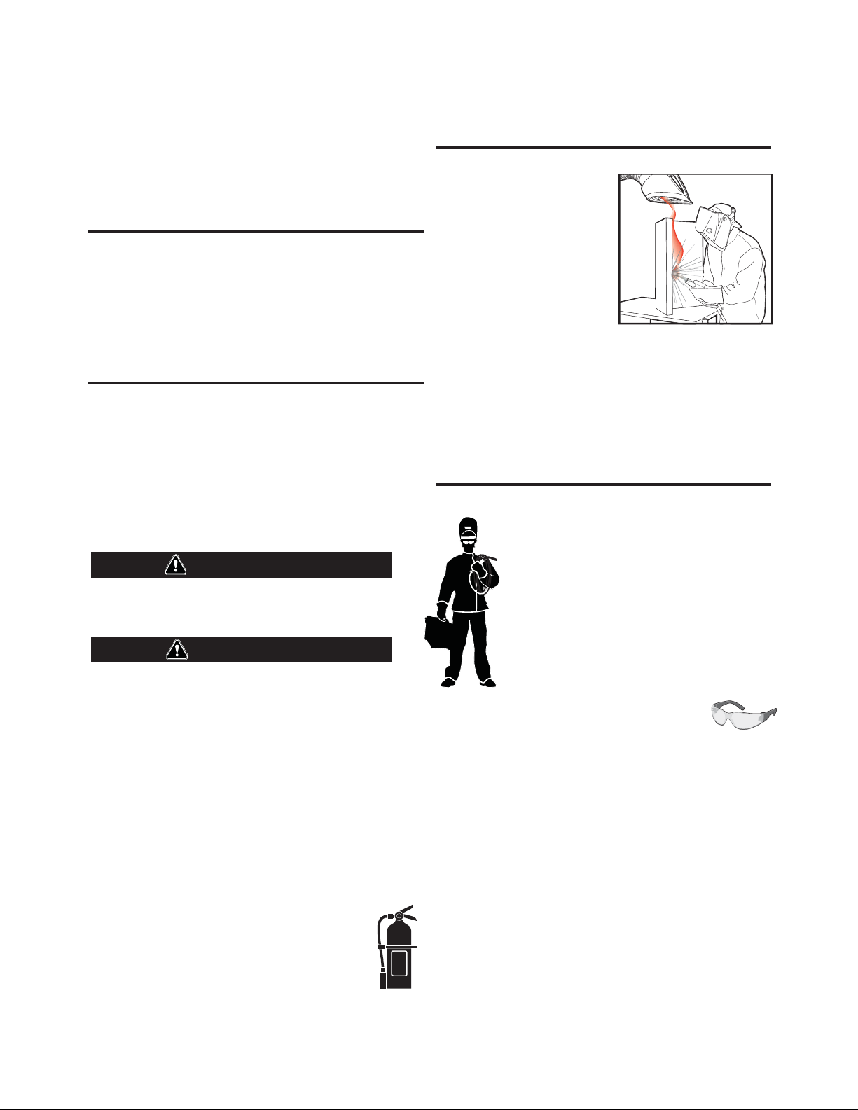
KEEP YOUR HEAD OUT OF THE FUMES.
DON’T get too close to the arc. Use
corrective lenses if necessary to
stay a reasonable distance away
from the arc.
READ and obey the Material Safety
Data Sheet (MSDS) and the warning
label that appears on all containers
of welding materials.
USE ENOUGH VENTILATION or
exhaust at the arc, or both, to keep
the fumes and gases from your breathing zone and the general area.
IN A LARGE ROOM OR OUTDOORS, natural ventilation may be
adequate if you keep your head out of the fumes (See below).
USE NATURAL DRAFTS or fans to keep the fumes away from your
face.
If you de velop unusual symptoms, see your supervisor. Perhaps the
welding atmosphere and ventilation system should be checked.
WEAR CORRECT EYE, EAR & BODY PROTECTION
PROTECT your eyes and face with welding helmet
properly fitted and with proper grade of filter plate
(See ANSI Z49.1).
PROTECT your body from welding spatter and arc
flash with protective clothing including woolen
clothing, flame-proof apron and gloves, leather
leggings, and high boots.
PROTECT others from splatter, flash, and glare with
protective screens or barriers.
IN SOME AREAS, protection from noise may be
appropriate.
BE SURE protective equipment is in good condition.
Also, wear safety glasses in work area
DO NOT WELD OR CUT containers or materials which previously had
been in contact with hazardous substances unless they are properly
cleaned. This is extremely dangerous.
DO NOT WELD OR CUT painted or plated parts unless special
precautions with ventilation have been taken. They can release highly
toxic fumes or gases.
PROTECT compressed gas cylinders from excessive heat, mechanical
shocks, and arcs; fasten cylinders so they cannot fall.
BE SURE cylinders are never grounded or part of an electrical circuit.
REMOVE all potential fire hazards from welding area.
ALWAYS HAVE FIRE FIGHTING EQUIPMENT READY FOR
IMMEDIATE USE AND KNOW HOW TO USE IT.
Page 3
SECTION A:
Diesel Engines
Gasoline Engines
WARNINGS
CALIFORNIA PROPOSITION 65 WARNINGS
Diesel engine exhaust and some of its constituents are known
to the State of California to cause cancer, birth defects, and other
reproductive harm.
The engine exhaust from this product contains chemicals known
to the State of California to cause cancer, birth defects, or other
reproductive harm.
ARC WELDING CAN BE HAZARDOUS. PROTECT
YOURSELF AND OTHERS FROM POSSIBLE SERIOUS
INJURY OR DEATH. KEEP CHILDREN AWAY. PACEMAKER WEARERS SHOULD CONSULT WITH THEIR
DOCTOR BEFORE OPERATING.
Read and understand the following safety highlights. For additional
safety information, it is strongly recommended that you purchase a
copy of “Safety in Welding & Cutting - ANSI Standard Z49.1” from the
American Welding Society, P.O. Box 351040, Miami, Florida 33135 or
CSA Standard W117.2-1974. A Free copy of “Arc Welding Safety”
booklet E205 is available from the Lincoln Electric Company, 22801
St. Clair Avenue, Cleveland, Ohio 44117-1199.
BE SURE THAT ALL INSTALLATION, OPERATION,
MAINTENANCE AND REPAIR PROCEDURES ARE
PERFORMED ONLY BY QUALIFIED INDIVIDUALS.
SAFETY
1.d. Keep all equipment safety guards, covers and
devices in position and in good repair.Keep
hands, hair, clothing and tools away from
V-belts, gears, fans and all other moving parts
when starting, operating or repairing
equipment.
1.e. In some cases it may be necessary to remove safety guards to
perform required maintenance. Remove guards only when
necessary and replace them when the maintenance requiring
their removal is complete. Always use the greatest care when
working near moving parts.
1.f. Do not put your hands near the engine fan. Do not attempt to
override the governor or idler by pushing on the throttle control
rods while the engine is running.
1.g. To prevent accidentally starting gasoline engines while turning
the engine or welding generator during maintenance work,
disconnect the spark plug wires, distributor cap or magneto wire
as appropriate.
1.h. To avoid scalding, do not remove the radiator
pressure cap when the engine is
hot.
ELECTRIC AND
MAGNETIC FIELDS MAY
BE DANGEROUS
2.a. Electric current flowing through any conductor
causes localized Electric and Magnetic Fields (EMF). Welding
current creates EMF fields around welding cables and welding
machines
FOR ENGINE POWERED
EQUIPMENT.
1.a. Turn the engine off before troubleshooting
and maintenance work unless the
maintenance work requires it to be running.
1.b. Operate engines in open, well-ventilated
areas or vent the engine exhaust fumes outdoors.
1.c. Do not add the fuel near an open flame
welding arc or when the engine is running.
Stop the engine and allow it to cool before
refueling to prevent spilled fuel from
vaporizing on contact with hot engine parts
and igniting. Do not spill fuel when filling
tank. If fuel is spilled, wipe it up and do not start engine until
fumes have been eliminated.
2.b. EMF fields may interfere with some pacemakers, and welders
having a pacemaker should consult their physician before
welding.
2.c. Exposure to EMF fields in welding may have other health effects
which are now not known.
2.d. All welders should use the following procedures in order to
minimize exposure to EMF fields from the welding circuit:
2.d.1. Route the electrode and work cables together - Secure
them with tape when possible.
2.d.2. Never coil the electrode lead around your body.
2.d.3. Do not place your body between the electrode and work
cables. If the electrode cable is on your right side, the
work cable should also be on your right side.
2.d.4. Connect the work cable to the workpiece as close as possible to the area being welded.
2.d.5. Do not work next to welding power source.
3
Page 4
SAFETY
ELECTRIC SHOCK
CAN KILL.
3.a. The electrode and work (or ground) circuits are
electrically “hot” when the welder is on. Do
not touch these “hot” parts with your bare skin
or wet clothing. Wear dry, hole-free gloves to insulate hands.
3.b. Insulate yourself from work and ground using dry insulation.
Make certain the insulation is large enough to cover your full area
of physical contact with work and ground.
In addition to the normal safety precautions, if
welding must be performed under electrically
hazardous conditions (in damp locations or while
wearing wet clothing; on metal structures such as
floors, gratings or scaffolds; when in cramped
positions such as sitting, kneeling or lying, if there
is a high risk of unavoidable or accidental contact
with the workpiece or ground) use the following
equipment:
• Semiautomatic DC Constant Voltage (Wire) Welder.
• DC Manual (Stick) Welder.
• AC Welder with Reduced Voltage Control.
3.c. In semiautomatic or automatic wire welding, the electrode,
electrode reel, welding head, nozzle or semiautomatic welding
gun are also electrically “hot”.
3.d. Always be sure the work cable makes a good electrical
connection with the metal being welded. The connection should
be as close as possible to the area being welded.
3.e. Ground the work or metal to be welded to a good electrical (earth)
ground.
3.f. Maintain the electrode holder, work clamp, welding cable and
welding machine in good, safe operating condition. Replace
damaged insulation.
3.g. Never dip the electrode in water for cooling.
3.h. Never simultaneously touch electrically “hot” parts of electrode
holders connected to two welders because voltage
two can be the total of the open circuit voltage of both
welders.
3.i. When working above floor level, use a safety belt to protect
yourself from a fall should you get a shock.
between the
ARC RAYS CAN BURN.
4.a. Use a shield with the proper filter and cover plates to protect your
eyes from sparks and the rays of the arc when welding or
observing open arc welding. Headshield and filter lens should
conform to ANSI Z87. I standards.
4.b. Use suitable clothing made from durable flame-resistant material
to protect your skin and that of your helpers from the arc rays.
4.c. Protect other nearby personnel with suitable, non-flammable
screening and/or warn them not to watch the arc nor expose
themselves to the arc rays or to hot spatter or metal.
FUMES AND GASES
CAN BE DANGEROUS.
5.a. Welding may produce fumes and gases
hazardous to health. Avoid breathing these
fumes and gases. When welding, keep your head out of the fume.
Use enough ventilation and/or exhaust at the arc to keep fumes
and gases away from the breathing zone. When welding
with electrodes which require special ventilation
such as stainless or hard facing (see instructions
on container or MSDS) or on lead or cadmium
plated steel and other metals or coatings which
produce highly toxic fumes, keep exposure as low
as possible and within applicable OSHA PEL and
ACGIH TLV limits using local exhaust or
mechanical ventilation. In confined spaces or in
some circumstances, outdoors, a respirator may
be required. Additional precautions are also
required when welding on galvanized steel.
5. b. The operation of welding fume control equipment is affected by
various factors including proper use and positioning of the
equipment, maintenance of the equipment and the specific
welding procedure and application involved. Worker exposure
level should be checked upon installation and periodically
thereafter to be certain it is within applicable OSHA PEL and
ACGIH TLV limits.
5.c. Do not weld in locations near chlorinated hydrocarbon vapors
coming from degreasing, cleaning or spraying operations. The
heat and rays of the arc can react with solvent vapors to form
phosgene, a highly toxic gas, and other irritating products.
3.j. Also see It ems 6.c. and 8.
5.d. Shielding gases used for arc welding can displace air and
injury or death. Always use enough ventilation, especially in
confined areas, to insure breathing air is safe.
5.e. Read and understand the manufacturer’s instructions for this
equipment and the consumables to be used, including the
material safety data sheet (MSDS) and follow your employer’s
safety practices. MSDS forms are available from your welding
distributor or from the manufacturer.
5.f. Also see item 1.b.
4
cause
Page 5
SAFETY
WELDING AND CUTTING
SPARKS CAN CAUSE
FIRE OR EXPLOSION.
6.a. Remove fire hazards from the welding area. If
this is not possible, cover them to prevent the
welding sparks from starting a fire. Remember that welding
sparks and hot materials from welding can easily go through
small cracks and openings to adjacent areas. Avoid welding near
hydraulic lines. Have a fire extinguisher readily available.
6.b. Where compressed gases are to be used at the job site, special
precautions should be used to prevent hazardous situations.
Refer to “Safety in Welding and Cutting” (ANSI Standard Z49.1)
and the operating information for the equipment being used.
6.c. When not welding, make certain no part of the electrode circuit is
touching the work or ground. Accidental contact can cause
overheating and create a fire hazard.
6.d. Do not heat, cut or weld tanks, drums or containers until the
proper steps have been taken to insure that such procedures will
not cause flammable or toxic vapors from substances inside.
They can cause an explosion even though they have been
“cleaned”. For information, purchase “Recommended Safe
Practices for the Preparation for Welding and Cutting of
Containers and Piping That Have Held Hazardous Substances”,
AWS F4.1 from the American Welding Society (see address
above).
6.e. Vent hollow castings or containers before heating, cutting or
welding. They may explode.
6.f. Sparks and spatter are thrown from the welding arc. Wear oil free
protective garments such as leather gloves, heavy shirt, cuffless
trousers, high shoes and a cap over your hair. Wear ear plugs
when welding out of position or in confined places. Always wear
safety glasses with side shields when in a welding area.
6.g. Connect the work cable to the work as close to the welding area
as practical. Work cables connected to the building framework or
other locations away from the welding area increase the
possibility of the welding current passing through lifting chains,
crane cables or other alternate circuits. This can create fire
hazards or overheat lifting chains or cables until they fail.
6.h. Also see item 1.c.
CYLINDER MAY EXPLODE IF
DAMAGED.
7.a. Use only compressed gas cylinders containing
the correct shielding gas for the process used
and properly operating regulators designed for
the gas and pressure used. All hoses, fittings,
etc. should be suitable for the application and
maintained in good condition.
7.b. Always keep cylinders in an upright position securely chained to
an undercarriage or fixed support.
7.c. Cylinders should be located:
• Away from areas where they may be struck or subjected
to physical damage.
• A safe distance from arc welding or cutting operations
and any other source of heat, sparks, or flame.
7.d. Never allow the electrode, electrode holder or any other
electrically “hot” parts to touch a cylinder.
7.e. Keep your head and face away from the cylinder valve outlet
when opening the cylinder valve.
7.f. Valve protection caps should always be in place and hand tight
except when the cylinder is in use or connected for use.
7.g. Read and follow the instructions on compressed gas cylinders,
associated equipment, and CGA publication P-l, “Precautions for
Safe Handling of Compressed Gases in
Cylinders,” available
from the Compressed Gas Association 1235 Jefferson Davis
Highway, Arlington, VA 22202.
FOR ELECTRICALLY
POWERED EQUIPMENT.
8.a. Turn off input power using the disconnect
switch at the fuse box before working on the
equipment.
8.b. Install equipment in accordance with the U.S. National Electrical
Code, all local codes and the manufacturer’s recommendations.
6.I. Read and follow NFPA 51B “ Standard for Fire Prevention During
Welding, Cutting and Other Hot Work”, available from NFPA, 1
Batterymarch Park, PO box 9101, Quincy, Ma 022690-9101.
6.j. Do not use a welding power source for pipe thawing.
8.c. Ground the equipment in accordance with the U.S. National
Electrical Code and the manufacturer’s recommendations.
Refer to
http://www.lincolnelectric.com/safety
for additional safety information.
Welding Safety
Interactive Web Guide
for mobile devices
5
Page 6
Thank You
vv
for selecting a QUALITY product by Lincoln Electric. We want you
to take pride in operating this Lincoln Electric Company product
••• as much pride as we have in bringing this product to you!
The business of The Lincoln Electric Company is manufacturing and selling high quality welding equipment, consumables, and cutting equipment. Our challenge is to meet the needs of our customers and to exceed their expectations. On occasion, purchasers may ask Lincoln
Electric for advice or information about their use of our products. We respond to our customers based on the best information in our possession at that time. Lincoln Electric is not in a position to warrant or guarantee such advice, and assumes no liability, with respect to such information or advice. We expressly disclaim any warranty of any kind, including any warranty of fitness for any customer’s particular purpose,
with respect to such information or advice. As a matter of practical consideration, we also cannot assume any responsibility for updating or
correcting any such information or advice once it has been given, nor does the provision of information or advice create, expand or alter any
warranty with respect to the sale of our products.
Lincoln Electric is a responsive manufacturer, but the selection and use of specific products sold by Lincoln Electric is solely within the control
of, and remains the sole responsibility of the customer. Many variables beyond the control of Lincoln Electric affect the results obtained in
applying these types of fabrication methods and service requirements.
Subject to Change – This information is accurate to the best of our knowledge at the time of printing. Please refer to www.lincolnelectric.com
for any updated information.
CUSTOMER ASSISTANCE POLICY
Please Examine Carton and Equipment For Damage Immediately
When this equipment is shipped, title passes to the purchaser upon receipt by the carrier. Consequently, Claims
for material damaged in shipment must be made by the purchaser against the transportation company at the
time the shipment is received.
Please record your equipment identification information below for future reference. This information can be
found on your machine nameplate.
Product _________________________________________________________________________________
Model Number ___________________________________________________________________________
Code Number or Date Code_________________________________________________________________
Serial Number____________________________________________________________________________
Date Purchased___________________________________________________________________________
Where Purchased_________________________________________________________________________
Whenever you request replacement parts or information on this equipment, always supply the information you
have recorded above. The code number is especially important when identifying the correct replacement parts.
On-Line Product Registration
- Register your machine with Lincoln Electric either via fax or over the Internet.
• For faxing: Complete the form on the back of the warranty statement included in the literature packet
accompanying this machine and fax the form per the instructions printed on it.
• For On-Line Registration: Go to our
Your Product”. Please complete the form and submit your registration.
Read this Operators Manual completely before attempting to use this equipment. Save this manual and keep it
handy for quick reference. Pay particular attention to the safety instructions we have provided for your protection.
The level of seriousness to be applied to each is explained below:
WEB SITE at www.lincolnelectric.com. Choose “Support” and then “Register
WARNING
This statement appears where the information must be followed exactly to avoid serious personal injury or loss of life.
CAUTION
This statement appears where the information must be followed to avoid minor personal injury or damage to this equipment.
Page 7

vi
TABLE OF CONTENTS
Page
Installation.......................................................................................................................Section A
Technical Specifications.......................................................................................................A-1
Safety Precautions ........................................................................................................A-2
Machine Grounding.......................................................................................................A-2
Spark Arrester ...............................................................................................................A-2
Towing...........................................................................................................................A-2
Vehicle Mounting...........................................................................................................A-3
Pre-Operation Engine Service..............................................................................................A-3
Fuel, Oil, Battery Connections ......................................................................................A-3
Welding Cable Connections..........................................................................................A-4
Angle of Operation ........................................................................................................A-4
Lifting, Additional Safety Precautions............................................................................A-4
High Altitude Operation .................................................................................................A-4
Muffler Outlet Pipe ........................................................................................................A-4
Location and Ventilation................................................................................................A-5
Stacking ........................................................................................................................A-5
Connection of Wire Feeders .........................................................................................A-5
Connection of Tig Module .............................................................................................A-5
Additional Safety Precautions .......................................................................................A-5
Welding Operation Output, Auxiliary Power Receptacles, and Plugs .................................A-6
Motor Starting and Extension Cord Length Table ................................................................A-6
Electrical Device Used with the
Auxiliary Power While Welding, Standby Power Connections ............................................A-8
Premises Wiring ...................................................................................................................A-9
________________________________________________________________________________
Operation.........................................................................................................................Section B
Safety Precautions ...............................................................................................................B-1
General Description..............................................................................................................B-1
Welder Controls Function and Operation .............................................................................B-1
Polarity, Range and Control Switch......................................................................................B-2
Start in/Shutdown Instructions.....................................................................................................B-3
Starting the Engine........................................................................................................B-3
Safety Precautions ........................................................................................................B-3
Stopping the Engine......................................................................................................B-3
Break-In Period .............................................................................................................B-3
Welding Process ..................................................................................................................B-4
Stick (Constant Current) Welding..................................................................................B-4
TIG (Constant Current) Welding ..................................................................................B-4
Wire Feed Welding Processes (Constant Voltage)......................................................B-4
Arc Gouging ..................................................................................................................B-4
Summary of Welding Processes ...................................................................................B-5
________________________________________________________________________________
Accessories ........................................................................................................Section C
Optional Equipment...............................................................................................C-1
Recommended Equipment....................................................................................C-2
________________________________________________________________________
Maintenance ....................................................................................................Section D
Safety Precautions ................................................................................................D-1
Routine Engine Maintenance ..........................................................................D-1,D2
Engine Adjustments...............................................................................................D-3
Slip Rings ..............................................................................................................D-3
Battery Maintenance .......................................................................................D-3
Engine Maintenance Parts..............................................................................D-3
________________________________________________________________________
Troubleshooting ..............................................................................................Section E
How to Use Troubleshooting Guide.......................................................................E-1
Troubleshooting Guide...................................................................................E-2, E-3
________________________________________________________________________
Wiring Diagrams, Connection Diagrams & Dimension Print.......................Section F
________________________________________________________________________
Parts List .....................................................................................................P-505, P-634
________________________________________________________________________
Ranger®250 GXT ...........................................................A-7
vi
Page 8

A-1
INSTALLATION
TECHNICAL SPECIFICATIONS - Ranger®250 GXT ( K2382-3, -4 and -5)
INPUT - GASOLINE ENGINE
Make/Model
Kohler
CH20S,
CH23S,
CH680
CH730
Description
2 cylinder
4 Cycle
Air-Cooled
Gasoline
Engine.
Aluminum Alloy
with Cast Iron
Liners,
Electronic
Ignition
RATED OUTPUT @ 104°F (40°C)- WELDER
RATED OUTPUT @ 104°F (40°C)- GENERATOR
Horsepower
23 HP @
3600 RPM
AC Constant Current 250A / 25V / 100%
DC Constant Current 250A / 25V / 100%
DC Constant Voltage 250A / 25V / 100%
Operating
Speed (RPM)
High Idle 3700
Full Load 3500
Low Idle 2200
Welding Output
Auxiliary Power
Displacement
cu. in.
(cu.cm.)
41.1(674)
44.2(724)
1
Starting
System
12VDC
Battery
Electric Start
Group 58
Battery
(435 cold
Cranking
Amps)
A-1
Capacities
Fuel:
12 Gal (45.4 L)
Lubricating Oil:
2.0 Qts. (1.9 L)
10,000 Watts Continuous, 60 Hz AC
11,000 Watts Peak, 60 Hz AC
120/240 Volts
RECEPTACLES AND CIRCUIT BREAKERS
RECEPTACLES
(2) 120VAC Duplex (5-20R)
(1) 120/240VAC Dual Voltage
Full KVA (14-50R)
AUXILIARY POWER CIRCUIT BREAKER
Two 20AMP for Two Duplex Receptacle
(1) 50AMP for Dual Voltage (2-pole)
BATTERY CHARGING CIRCUIT BREAKER
20AMP for Engine Battery
Charging Circuit
PHYSICAL DIMENSIONS
HEIGHT WIDTH DEPTH WEIGHT
Codes 11800 and below
30.00** in. 21.50 in 42.25 in.
762.0 mm 546.0 mm 1073.0 mm
** Top of enclosure, add 6.00”(152mm) for exhaust.
567 lbs. (257kg.)
Codes 12095, 12096
574 lbs. (260kg.)
ENGINE COMPONENTS
LUBRICATION VALVE LIFTERS FUEL SYSTEM GOVERNOR
Full Pressure Hydraulic Mechanical Fuel Pump on K2382-3 Mechanical Governor
with Full Flow Filter Additional electric fuel lift pump
5% Regulation on K2382-4, -5.
AIR CLEANER ENGINE IDLER MUFFLER ENGINE PROTECTION
Low noise Muffler: Top outlet Shutdown on low oil
Dual Element Automatic Idler can be rotated. Made from pressure.
long life, aluminized steel.
1
Output rating in watts is equivalent to volt - amperes at unity factor.Output voltage is within +/-10% at all loads up to rated capacity.
When welding available auxiliary power will be reduced.
RANGER®250 GXT
Page 9
A-2
INSTALLATION
A-2
SAFETY PRECAUTIONS
WARNING
Do not attempt to use this equipment until you
have thoroughly read the engine manufacturerʼs
manual supplied with your welder. It includes
important safety precautions, detailed engine
starting, operating and maintenance instructions,
and parts lists.
------------------------------------------------------------------------
ELECTRIC SHOCK can kill.
• Do not touch electrically live parts or
electrode with skin or wet clothing.
• Insulate yourself from work and
ground
• Always wear dry insulating gloves.
------------------------------------------------------------------------
ENGINE EXHAUST can kill.
• Use in open, well ventilated areas or
vent exhaust outside.
------------------------------------------------------------------------
MOVING PARTS can injure.
• Do not operate with doors open or
guards off.
• Stop engine before servicing.
• Keep away from moving parts.
------------------------------------------------------------------------
When this welder is mounted on a truck or trailer, itʼs
frame must be electrically bonded to the metal frame
of the vehicle. Use a #8 or larger copper wire connected between the machine grounding stud and the
frame of the vehicle.
Where this engine driven welder is connected to
premises wiring such as that in your home or shop, itʼs
frame must be connected to the system earth ground.
See further connection instructions in the section entitled “Standby Power Connections”, as well as the article on grounding in the latest National Electrical Code
and the local code.
In general, if the machine is to be grounded, it should
be connected with a #8 or larger copper wire to a solid
earth ground such as a metal water pipe going into
the ground for at least ten feet and having no insulated joints, or to the metal framework of a building
which has been effectively grounded. The National
Electrical Code lists a number of alternate means of
grounding electrical equipment. A machine grounding
stud marked with the symbol is provided on the
front of the welder.
SPARK ARRESTER
See additional warning information at
front of this operatorʼs manual.
-----------------------------------------------------------
MACHINE GROUNDING
Because this portable engine driven welder or generator creates itʼs own power, it is not necessary to connect itʼs frame to an earth ground, unless the machine
is connected to premises wiring (your home, shop,
etc.).
WARNING
To prevent dangerous electric shock, other equipment to which this engine driven welder supplies
power must:
• be grounded to the frame of the welder using a
grounded type plug, or be double insulated.
Do not ground the machine to a pipe that carries
explosive or combustible material.
------------------------------------------------------------------------
Some federal, state, or local laws may require that
gasoline engines be equipped with exhaust spark
arresters when they are operated in certain locations
where unarrested sparks may present a fire hazard.
The standard muffler included with this welder does
not qualify as a spark arrester. When required by local
regulations, the K1898-1 spark arrester must be
installed and properly maintained.
CAUTION
An incorrect arrester may lead to damage to the
engine or adversely affect performance.
------------------------------------------------------------------------
TOWING
The recommended trailer for use with this equipment
for road, in-plant and yard towing by a vehicle
Lincolnʼs K957-1. If the user adapts a non-Lincoln
trailer, he must assume responsibility that the method
of attachment and usage does not result in a safety
hazard nor damage the welding equipment. Some of
the factors to be considered are as follows:
1. Design capacity of trailer vs. weight of Lincoln
equipment and likely additional attachments.
(1)
is
2. Proper support of, and attachment to, the base of
the welding equipment so there will be no undue
stress to the framework.
RANGER®250 GXT
Page 10
A-3
3. Proper placement of the equipment on the trailer to
insure stability side to side and front to back when
being moved and when standing by itself while
being operated or serviced.
4. Typical conditions of use, i.e., travel speed; rough-
ness of surface on which the trailer will be operated;
environmental conditions.
5. Conformance with federal, state and local laws
(1) Consult applicable federal, state and local laws regarding specific
requirements for use on public highways.
VEHICLE MOUNTING
INSTALLATION
(1)
WARNING
Improperly mounted concentrated loads may
cause unstable vehicle handling and tires or other
components to fail.
• Only transport this Equipment on serviceable
vehicles which are rated and designed for such
loads.
• Distribute, balance and secure loads so vehicle
is stable under conditions of use.
• Do not exceed maximum rated loads for components such as suspension, axles and tires.
• Mount equipment base to metal bed or frame of
vehicle.
• Follow vehicle manufacturerʼs instructions.
------------------------------------------------------------------------
PRE-OPERATION SERVICE
CAUTION
READ the engine operating and maintenance
instructions supplied with this machine.
A-3
FUEL
Fill the fuel tank with clean, fresh, lead-free gasoline.
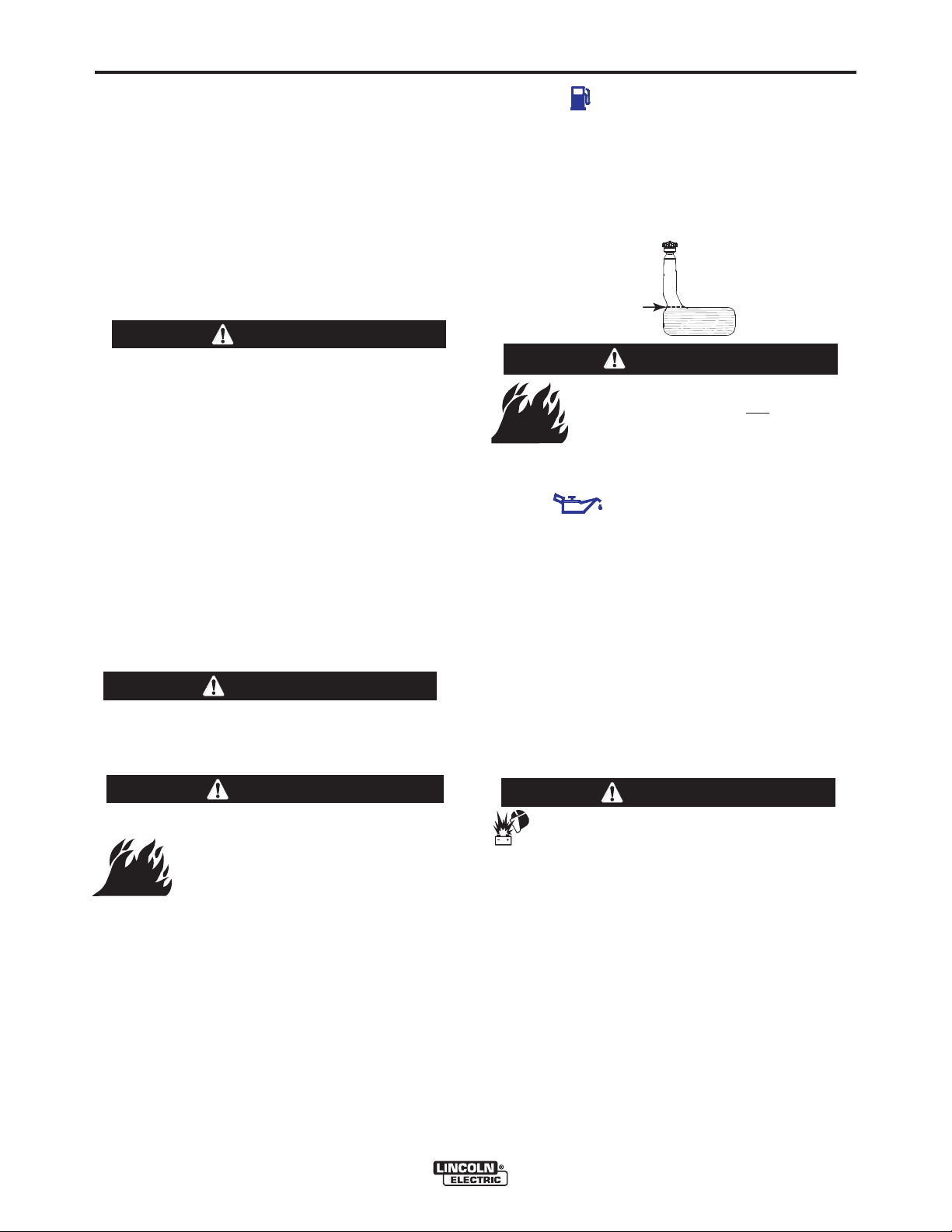
Observe fuel gauge while filling to prevent overfilling.
Stop fueling once the fuel gauge reads full. Do not top
off tank. Be sure to leave filler neck empty to allow
room for expansion.
FULL
WARNING
• Damage to the fuel tank may cause
fire or explosion. Do not
in the RANGER
-----------------------------------------------------------------------
OIL
LUBRICATION SYSTEM CAPACITY
Kohler CH20S, CH23S, CH680, CH730 - 2.0 Quarts (1.9 Liters)
The RANGER
crankcase filled with SAE 10W-30 oil. Check the oil
level before starting the engine. If it is not up to the full
mark on the dip stick, add oil as required. Make certain that the oil filler cap is tightened securely. Refer to
the engine Ownerʼs Manual for specific oil recommendations.
to the RANGER
(INCLUDING FILTER)
®
GXT is shipped with the engine
®
GXT base or weld
®
GXT base.
BATTERY CONNECTIONS
drill holes
WARNING
• Stop engine while fueling.
• Do not smoke when fueling.
• Keep sparks and flame away from
tank.
• Do not leave unattended while
fueling.
• Wipe up spilled fuel and allow
GASOLINE
can cause fire
or explosion.
------------------------------------------------------------------------
fumes to clear before starting
engine.
• Do not overfill tank, fuel expansion may cause overflow.
GASOLINE FUEL ONLY
RANGER®250 GXT
CAUTION
Use caution as the electrolyte is a strong
acid that can burn skin and damage eyes.
------------------------------------------------------------------------
This welder is shipped with the negative battery cable
disconnected. Make sure that the Engine Switch is in
the “STOP” position and attach the disconnected
cable securely to the negative battery terminal before
attempting to operate the machine. If the battery is
discharged and does not have enough power to start
the engine, see the battery charging instructions in the
Battery section.
NOTE: This machine is furnished with a wet charged
battery; if unused for several months, the battery may
require a booster charge. Be careful to charge the battery with the correct polarity.
Page 11
A-4
INSTALLATION
WELDING OUTPUT CABLES
With the engine off, connect the electrode and work
cables to the studs provided. These connections
should be checked periodically and tightened if necessary. Loose connections will result in overheating of
the output studs.
When welding at a considerable distance from the
welder, be sure you use ample size welding cables.
Listed below are copper cable sizes recommended for
the rated current and duty cycle. Lengths stipulated
are the distance from the welder to work and back to
the welder again. Cable sizes are increased for
greater lengths primarily for the purpose of minimizing
cable voltage drop.
TOTAL COMBINED LENGTH OF
ELECTRODE AND WORK CABLES
250 Amps
100% Duty Cycle
0-100 Ft. (0-31m)
100-150 Ft. (31-46m)
150-200 Ft. (46-61m)
1 AWG
1 AWG
1/0 AWG
ANGLE OF OPERATION
Internal combustion engines are designed to run in a
level condition which is where the optimum performance is achieved. The maximum angle of operation
for the engine is 15 degrees from horizontal in any
direction. If the engine is to be operated at an angle,
provisions must be made for checking and maintaining the oil at the normal (FULL) oil capacity in the
crankcase in a level condition.
When operating at an angle, the effective fuel capacity
will be slightly less than the specified 12 Gal. (45 L).
A-4
ADDITIONAL SAFETY PRECAUTION
WARNING
• Lift only with equipment of
adequate lifting capacity.
• Be sure machine is stable
when lifting.
• Do not lift this machine using
lift bail if it is equipped with a
heavy accessory such as trailer or gas cylinder.
FALLING • Do not lift machine if lift bail is
EQUIPMENT can damaged.
cause injury. • Do not operate machine while
suspended from lift bail.
------------------------------------------------------------------------
HIGH ALTITUDE OPERATION
At higher altitudes, Welder output de-rating may be
necessary. For maximum rating, de-rate the welder
output 3.5% for every 1000 ft. (305m) above 3000 ft.
(914m). If operation will consistently be at altitudes
above 5,000 ft. (1525m), a carburetor jet designed for
high altitudes should be installed. This will result in
better fuel economy, cleaner exhaust and longer
spark plug life. It will not give increased power.
Contact your local authorized engine service shop for
high altitude jet kits that are available from the engine
manufacturer.
CAUTION
Do not operate with a high altitude jet installed at
altitudes below 5000 ft. This will result in the
engine running too lean and result in higher
engine operating temperatures which can shorten
engine life.
------------------------------------------------------------------------
MUFFLER OUTLET PIPE
LIFTING
The Ranger®250 GXT weighs approximately
646lbs.(293kg) with a full tank of gasoline. A lift bail is
mounted to the machine and should always be used
when lifting the machine.
RANGER®250 GXT
Using the clamp provided secure the outlet pipe to the
outlet tube with the pipe positioned such that it will
direct the exhaust in the desired direction. Tighten
using a 9/16” socket or wrench.
Page 12

A-5
INSTALLATION
LOCATION / VENTILATION
The welder should be located to provide an unrestricted flow of clean, cool air to the cooling air inlets and to
avoid heated air coming out of the welder recirculating
back to the cooling air inlet. Also, locate the welder so
that engine exhaust fumes are properly vented to an
outside area.
STACKING
Ranger®250 GXT machines cannot be stacked.
CONNECTION OF LINCOLN ELECTRIC
WIRE FEEDERS
WARNING
Shut off welder before making any electrical
connections.
-----------------------------------------------------------------------
WIRE FEED (CONSTANT VOLTAGE)
CONNECTION OF LN-15 ACROSS-THE-ARC WIRE
FEEDER
The LN-15 has an internal contactor and the electrode
is not energized until the gun trigger is closed. When
the gun trigger is closed the wire will begin to feed and
the welding process is started.
• Shut the welder off.
Connect the electrode cable from the LN-15 to
•
“ELECTRODE” terminal of the welder. Connect
the
the work cable to the “TO WORK” terminal of the
welder.
• Set the Polarity switch to the desired polarity, either
DC (-) or DC (+).
• Attach the single lead from the front of the LN-15
to work using the spring clip at the end of the lead.
This is a control lead to supply current to the wire
feeder motor; it does not carry welding current.
• Set the “RANGE” switch to the “WIRE FEED-CV”
position
• Place the Engine switch in the “Auto Idle” position
when welding with MIG wire instead of self-shielded
core wire, weld starts can be improved by setting
the idle mode to “HIGH”.
• Adjust the wire feed speed at the LN-15 and adjust
the welding voltage with the output “CONTROL” at
the welder.
when welding with MIG wire instead of self-shielded
core wire, weld starts can be improved by setting
the idle mode to “HIGH”
Note: LN-15 Control Cable model will not work with
Output “CONTROL” must be set above 3
.
the Ranger
®
250 GXT.
A-5
• Position the “RANGE” switch to the “WIRE FEED
CV” position.
• Attach the single lead from the LN-25 control box
to the work using the spring clip on the end of the
lead - it carries no welding current.
• Place the engine switch in the “AUTO IDLE” position.
• When welding with MIG wire instead of selfshielded core wire, weld starts can be improved
by setting the idle mode to “HIGH”
• Adjust wire feed speed at the LN-25 and adjust
the welding voltage with the output “CONTROL”
at the welder.
NOTE: The welding electrode is energized at all
times, unless an LN-25 with built-in contactor is used.
If the output “CONTROL” is set below “3”, the LN-25
contactor may not pull in.
CONNECTION OF THE LN-25 TO THE
GXT
• Shut the welder off.
Connect the electrode cable from the LN-25 to
•
“ELECTRODE” terminal of the welder.
the
Connect the work cable to the “TO WORK” terminal of the welder.
• Position the welder “Polarity” switch to the desired
polarity, either DC (-) or DC (+).
CONNECTION OF K930-2 TIG MODULE TO THE
RANGER
The TIG Module is an accessory that provides high
frequency and shielding gas control for AC and DC
GTAW (TIG) welding. See IM528 supplied with the
TIG Module for installation instructions.
Note: The TIG Module does not require the use of a
high frequency bypass capacitor. However, if the
Ranger
cy equipment, the bypass capacitor must be installed,
order kit T12246.
®
250 GXT.
®
250 GXT is used with any other high frequen-
.
RANGER®250
INSTRUCTIONS
ADDITIONAL SAFETY PRECAUTIONS
Always operate the welder with the roof and case
sides in place as this provides maximum protection
from moving parts and assures proper cooling air flow.
Read and understand all Safety Precautions before
operating this machine. Always follow these and any
other safety procedures included in this manual and in
the Engine Ownerʼs Manual.
RANGER®250 GXT
Page 13
A-6
INSTALLATION
WELDER OPERATION
WELDER OUTPUT
• Maximum Open Circuit Voltage at 3700 RPM is
80 Volts RMS.
• Duty Cycle is the percentage of time the load is
being applied in a 10 minute period. For example, a
60% duty cycle represents 6 minutes of load and 4
minutes of no load in a 10 minute period. Duty
®
Cycle for the Ranger
250 GXT is 100%.
Ranger®250 GXT
Constant Current 250 Amps AC @ 25 Volts
250 Amps DC @ 25 Volts
Constant Voltage 250 Amps DC @ 25 Volts
AUXILIARY POWER
A-6
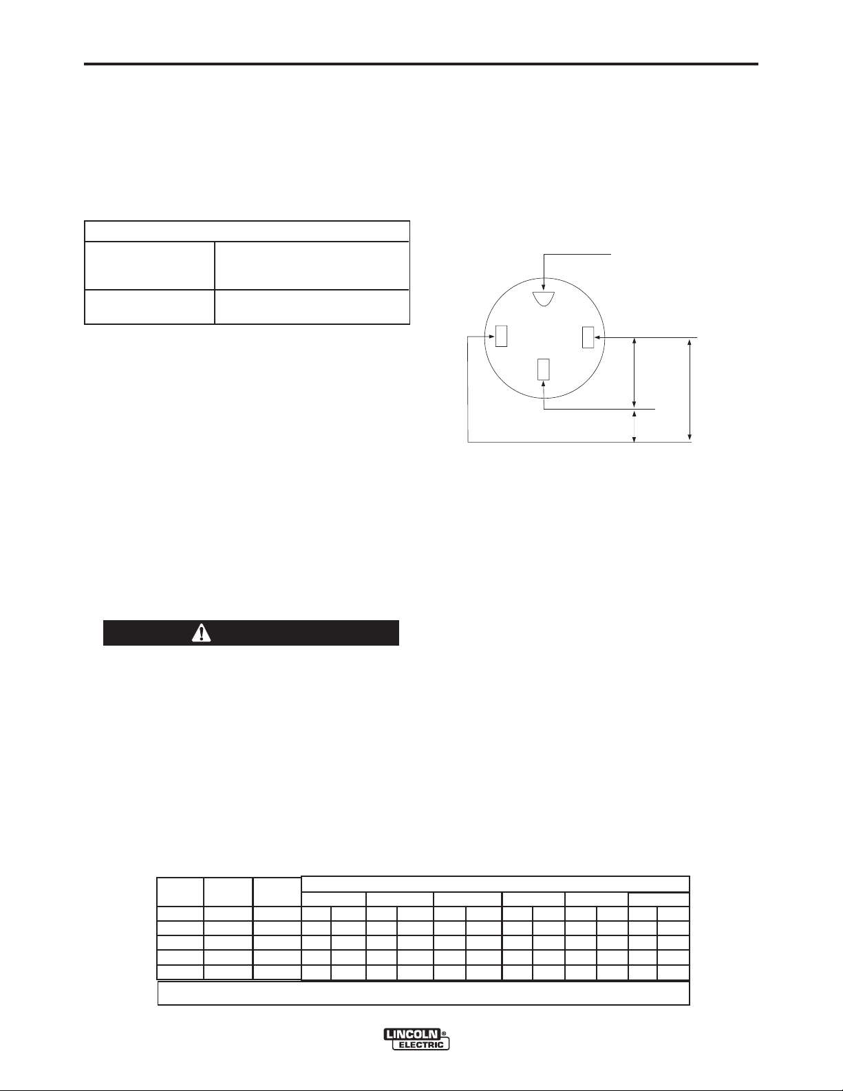
120/240 VOLT DUAL VOLTAGE RECEPTACLE
The 120/240 volt receptacle can supply up to 42
amps of 240 volt power to a two wire circuit, up to 42
amps of 120 volts power from each side of a three
wire circuit (up to 84 amps total). Do not connect the
120 volt circuits in parallel. Current sensing for the
automatic idle feature is only in one leg of the three
wire circuit as shown in the following column.
GND
The Ranger®250 GXT can provide up to 10,000 watts
of 120/240 volts AC, single phase 60Hz power for
continuous use, and up to 11,000 watts of 120/240
volts AC, single phase 60Hz power peak use. The
front of the machine includes three receptacles for
connecting the AC power plugs; one 50 amp 120/240
volt NEMA 14-50R receptacle and two 20 amp 120
volt NEMA 5-20R receptacles. Output voltage is within
+/-10% at all loads up to rated capacity.
All auxiliary power is protected by circuit breakers. the
120V has 20 Amp circuit breakers for each duplex
receptacle. The 120/240V Single Phase has a 50 Amp
2-pole Circuit Breaker that disconnects both hot leads
simultaneously.
CAUTION
Do not connect any plugs that connect to the
power receptacles in parallel.
------------------------------------------------------------------------
Start the engine and set the “IDLER” control switch to
the desired operating mode. Set the “CONTROL” to
10. Voltage is now correct at the receptacles for auxiliary power.
120 V
240 V
120 V*
*Current Sensing for Automatic Idle.
(Receptacle viewed from front of Machine)
120 V DUPLEX RECEPTACLES
The 120V auxiliary power receptacles should only be
used with three wire grounded type plugs or approved
double insulated tools with two wire plugs.
The current rating of any plug used with the system
must be at least equal to the current load through the
associated receptacle.
MOTOR STARTING
Most 1.5 hp AC single phase motors can be started if
there is no load on the motor or other load connected
to the machine, since the full load current rating of a
1.5 hp motor is approximately 20 amperes (10
amperes for 240 volt motors). The motor may be run
at full load when plugged into only one side of the
duplex receptacle. Larger motors through 2 hp can be
run provided the receptacle rating as previously stated
is not exceeded. This may necessitate 240V operation
only.
Ranger®250 GXT Extension Cord Length Recommendations
(Use the shortest length extension cord possible sized per the following table.)
Current
(Amps)
15
20
15
20
42
Voltage
Volts
120
120
240
240
240
Load
(Watts)
1800
2400
3600
4800
10,000
Conductor size is based on maximum 2.0% voltage drop.
Maximum Allowable Cord Length in ft. (m) for Conductor Size
14 AWG
30 (9)
60 (18)
12 AWG
40 (19)
30 (9)
75 (23)
60 (18)
10 AWG
75 (23)
50 (15)
150 (46)
100 (30)
50 (15)
8 AWG
125 (38)
88 (27)
225 (69)
175 (53)
90 (27)
6 AWG
175 (53)
138 (42)
350 (107)
275 (84)
150 (46)
RANGER®250 GXT
4 AWG
300 (91)
225 (69)
600 (183)
450 (137)
225 (69)
Page 14

A-7
INSTALLATION
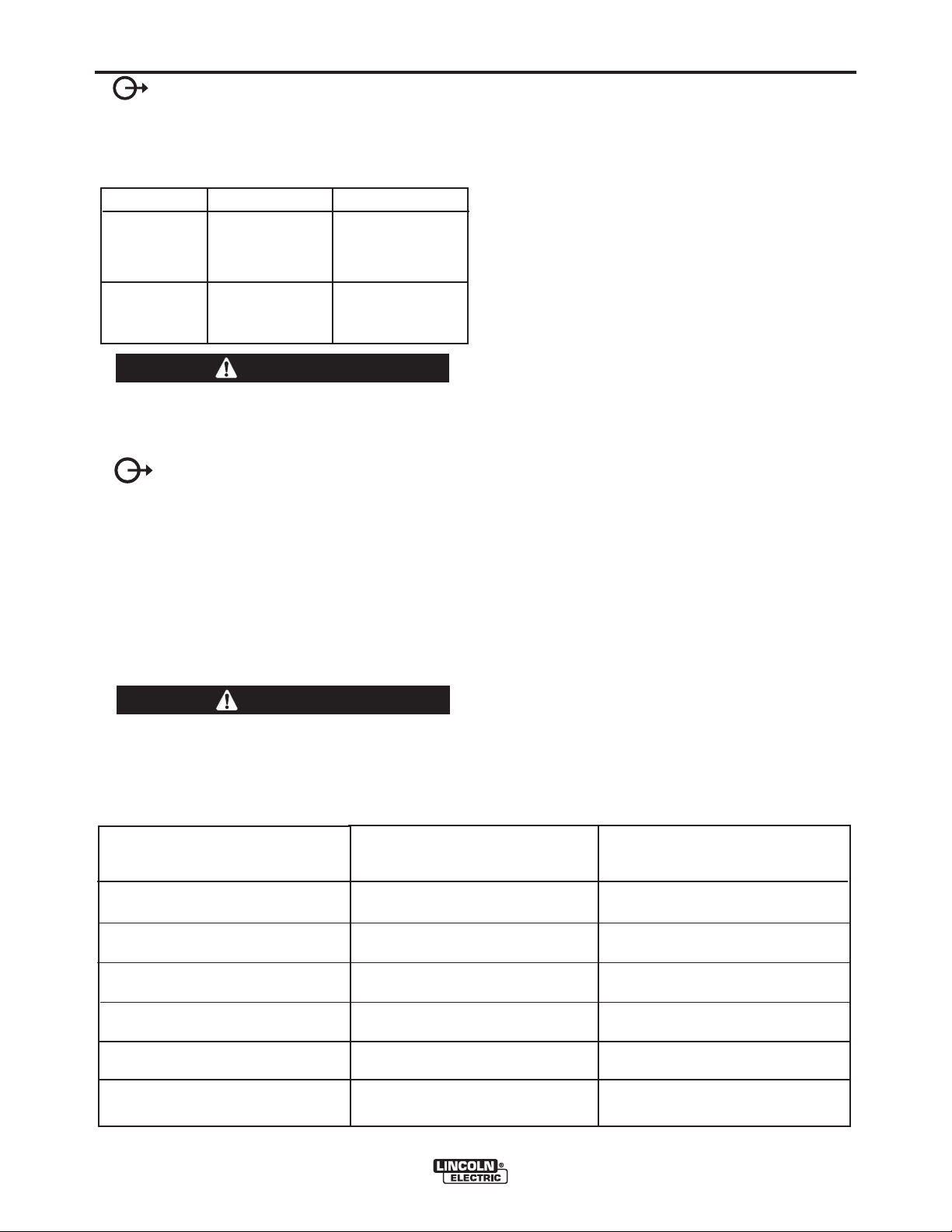
CAUTION
Certain Electrical devices cannot be powered to this Product. See Table A.2
TABLE lll
ELECTRICAL DEVICE USE WITH THIS PRODUCT
Type Common Electrical Devices Possible Concerns
Resistive Heaters, toasters, incandescent NONE
light bulbs, electric range, hot
pan, skillet, coffee maker.
Capacitive TV sets, radios, microwaves, Voltage spikes or high voltage
appliances with electrical control. regulation can cause the capaci-
tative elements to fail. Surge
protection, transient protection,
and additional loading is recommended for 100% fail-safe oper-
ation. DO NOT RUN THESE
DEVICES WITHOUT ADDITIONAL RESISTIVE TYPE
LOADS.
A-7
Inductive Single-phase induction motors, These devices require large
drills, well pumps, grinders, small current inrush for starting.
refrigerators, weed and hedge Some synchronous motors may
trimmers be frequency sensitive to attain
maximum output torque, but
they SHOULD BE SAFE from
any frequency induced failures.
Capacitive/Inductive Computers, high resolution TV sets, An inductive type line condition-
complicated electrical equipment. er along with transient and
surge protection is required, and
liabilities still exist. DO NOT
USE THESE DEVICES WITH
THIS PRODUCT
The Lincoln Electric Company is not responsible for any damage to electrical components
improperly connected to this product.
RANGER®250 GXT
Page 15

A-8
INSTALLATION
AUXILIARY POWER WHILE WELDING
Simultaneous welding and power loads are permitted
by following Table I. The permissible currents shown
assume that current is being drawn from either the
120V or 240V supply (not both at the same time).
Also, the “Output Control” is set at “10” for maximum
auxiliary power.
TABLE I
SIMULTANEOUS WELDING AND POWER
Output Selector Permissible Power Permissible Auxiliary
Setting Watts (Unity Power Current in Amperes
Factor) @ 120V
Max. Stick or Wire
Feed Setting None 0 0
180 Stick Setting 5100 42 21
130 Stick Setting 7200 60
80 Stick Setting 8750 72
*-or- @ 240V
** 30
** 36
A-8
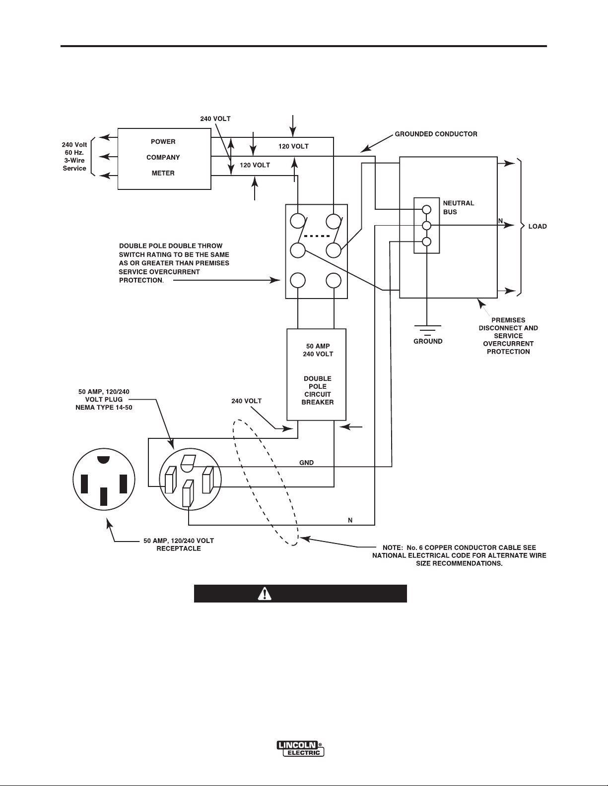
1. Install a double pole, double throw switch between
the power company meter and the premises
disconnect.
Switch rating must be the same or greater than
the customerʼs premises disconnect and service
overcurrent protection.
2. Take necessary steps to assure load is limited to
the capacity of the Ranger
50 amp 240V double pole circuit breaker.
Maximum rated load for the 240V auxiliary is 42
amperes. Loading above 42 amperes will reduce
output voltage below the allowable -10% of rated
voltage which may damage appliances or other
motor-driven equipment.
3. Install a 50 amp 120/240V plug (NEMA type 14-50)
to the Double Pole Circuit Breaker using No. 8,
4 conductor cable of the desired length. (The
50 amp 120/240V plug is available in the
optional plug kit.)
®
250 GXT by installing a
No Welding 10,000 84
** 42
* Each duplex receptacle is limited to 20 amps.
**Not to exceed 50A per 120VAC branch circuit when
splitting the 240 VAC output.
STANDBY POWER CONNECTIONS
®
The Ranger
250 GXT is suitable for temporary, standby, or emergency power using the engine manufacturerʼs recommended maintenance schedule.
The Ranger
®
250 GXT can be permanently installed as
a standby power unit for 240V-3 wire, single phase 42
ampere service.
WARNING
(Connections must be made by a licensed electrician who can determine how the 120/240V power
can be adapted to the particular installation and
comply with all applicable electrical codes.) The
following information can be used as a guide by
the electrician for most applications (refer also to
the connection diagram shown in Figure 1.)
------------------------------------------------------------------------
4. Plug this cable into the 50 amp 120/240V
®
receptacle on the Ranger
250 GXT case front.
RANGER®250 GXT
Page 16
A-9
INSTALLATION
Figure 1
CONNECTION OF Ranger®250 GXT TO PREMISES WIRING
A-9
WARNING
Connection of Ranger®250 GXT to premises
wiring must be done by a licensed electrician and
must comply with the National Electrical Code and
all other applicable electrical codes.
RANGER®250 GXT
Page 17

B-1
OPERATION
SAFETY PRECAUTIONS
Do not attempt to use this equipment until you
have thoroughly read the engine manufacturerʼs
manual supplied with your welder. It includes
important safety precautions, detailed engine
starting, operating and maintenance instructions,
and parts lists.
------------------------------------------------------------------------
ELECTRIC SHOCK can kill.
• Do not touch electrically live parts or
electrode with skin or wet clothing.
Insulate yourself from work and
•
ground
• Always wear dry insulating gloves.
• Always operate the welder with the hinged door
closed and the side panels in place.
B-1
WELDER CONTROLS - FUNCTION AND
OPERATION
ENGINE SWITCH
The engine switch is used to Start the Engine, Select
High Idle or Auto Idle while the engine is running, and
stop the Engine.
When placed in the “OFF” position, the ignition
circuit is de-energized to shut down the engine.
When held in the “START” position, the engine
starter motor is energized.
When in “HIGH IDLE” ( ) position, the engine will
run continuously at high idle.
• Read carefully the Safety Precautions page
before operating this machine. Always follow
these and any other safety procedures included
in this manual and in the Engine Instruction
Manual.
------------------------------------------------------------------------
GENERAL DESCRIPTION
The Ranger®250 GXT is a twin-cylinder, gasoline driven, multiprocess arc welder and AC power generator. It is built in a heavy gauge steel case for durability
on the job site.
Codes 11792 and above meet EPA evaporative emission requirements.
When in “AUTO IDLE” ( / ) position, the
engine will run continuously and the idler operates as
follows:
• Welding
When the electrode touches the work, the welding
arc is initiated and the engine accelerates to full
speed.
After welding ceases (and no auxiliary power is
being drawn), the engine will return to low idle
after approximately 10 to 14 seconds.
• Auxiliary Power
With the engine running at low idle and auxiliary
power for lights or tools is drawn (approximately
100-150 watts or greater) from the receptacles,
the engine will accelerate to high speed. If no
power is being drawn from the receptacles (and
not welding) for 10-14 seconds, the idler reduces
the engine speed to low idle.
RANGER®250 GXT
Page 18
B-2
“ RANGE” SWITCH
OPERATION
6-PIN CONNECTOR
B-2
The “Range” switch is used to select one of four
amperage ranges with generous overlap for Stick/TIG
welding, or one Wire Feed welding range.
Process Range Setting Current Range
STICK/TIG
(constant current)
(4 range settings)
WIRE FEED
(constant voltage)
(2 range setting)
80 Max.
130 Max.
180 Max.
250 Max.
14 to 22V
18 to 28V
50 to 80 Amps
70 to 130 Amps
110 to 180 Amps
160 to 250 Amps
Up to 250 Amps
CAUTION
Never change the “RANGE” Switch setting while
welding. This will damage the switch.
------------------------------------------------------------------------
“ CONTROL” DIAL
Provides a fine welding current adjustment within the
Range Switch settings in the STICK mode and welding voltage control with the Range switch set in the
wire feed mode.
For attaching optional remote control equipment.
LOCAL / REMOTE CONTROL SWITCH
(See Accessory Section For “K” numbers)
The toggle switch on the control panel labeled
"LOCAL" and "REMOTE" provides the option of controlling the welding output at the control panel or
remotely. Remote connections are made at the 6-pin
connector. For control at the control panel set the
switch in the "LOCAL" position.
For remote control set the switch in the "REMOTE"
position.
POLARITY SWITCH
Provides three selectable welding polarities:
AC, DC+ & DC-
CAUTION
Never change the Polarity switch setting while
welding. This will damage the switch.
------------------------------------------------------------------------
RANGER®250 GXT APPROXIMATE FUEL CONSUMPTION
KOHLER
23 H.P. COMMAND (CH23S, CH680)
Low Idle - No Load
2400 RPM
High Idle - No Load
3700 RPM
AC CC Weld Output
250 Amps @ 25 Volts
DC CC Weld Output
250 Amps @ 25 Volts
DC CV Weld Output
250 Amps @ 25 Volts
Auxiliary Power
10,000 Watts
.40 Gallons/Hour
(1.51 Liters/Hour)
.77 Gallons/Hour
(2.91 Liters/Hour)
1.27 Gallons/Hour
(4.82 Liters/Hour)
1.50 Gallons/Hour
(5.69 Liters/Hour)
1.41 Gallons/Hour
(5.33 Liters/Hour)
1.48 Gallons/Hour)
(5.62 Liters/Hour)
KOHLER
23 H.P. COMMAND (CH730)
.40 Gallons/Hour
(1.51 Liters/Hour)
.93 Gallons/Hour
(3.52 Liters/Hour)
1.50 Gallons/Hour
(5.69 Liters/Hour)
1.74 Gallons/Hour
(6.59 Liters/Hour)
1.62 Gallons/Hour
(6.13 Liters/Hour)
1.90 Gallons/Hour)
(7.19 Liters/Hour)
RANGER®250 GXT
Page 19
B-3
OPERATION
B-3
STARTING/SHUTDOWN INSTRUCTIONS
STARTING THE ENGINE
WARNING
• Do not touch electrically live parts
of electrode with skin or wet
clothing.
• Keep flammable material away.
• Insulate yourself from work and
ground. Wear eye, ear, and body
protection.
• Keep your head out of the fumes.
• Use ventilation or exhaust to
remove fumes from breathing zone.
Be sure all Pre-Operation Maintenance has been performed. Also, read the Engine Ownerʼs Manual before
starting for the first time.
Remove all loads connected to the AC power receptacles. Use the choke control as follows:
KOHLER ENGINE - Always pull the choke control out
when starting the engine; cold, warm or hot.
STOPPING THE ENGINE
Remove all welding and auxiliary power loads and
allow engine to run at low idle speed for a few minutes
to cool the engine.
Stop the engine by placing the Engine switch in the
“OFF” position.
A fuel shut off valve is not required on the Ranger
250 GXT because the fuel tank is mounted below the
engine.
BREAK-IN PERIOD
It is normal for any engine to use a greater amount of
oil until the break-in is accomplished. Check the oil
level twice a day during the break-in period (approximately 50 running hours).
IMPORTANT: IN ORDER TO ACCOMPLISH THIS
BREAK-IN, THE UNIT SHOULD BE
SUBJECTED TO MODERATE
LOADS, WITHIN THE RATING OF
THE MACHINE. AVOID LONG IDLE
RUNNING PERIODS. REMOVE
LOADS AND ALLOW ENGINE TO
COOL BEFORE SHUTDOWN.
The engine manufacturerʼs recommendation for the
running time until the first oil change is as follows:
®
Turn the engine switch to the “start” posi tion and
crank the engine until it starts. Release the switch as
soon as the engine starts, slowly return the choke
control to the full “in” position (choke open),
and turn the switch to the Auto Idle( / )
position. Do not turn the switch to the “start” position
while the engine is running because this will cause
damage to the ring gear and/or starter motor
After running at high engine speed for 10-14 seconds,
the engine will go to low idle.
Allow the engine to warm up by letting it run at low idle
for a few minutes.
RANGER®250 GXT
KOHLER
CH23S, CH680, CH730
5 HRS
The oil filter is to be changed at the second oil
change. Refer to the Engine Ownerʼs Manual for more
information.
Page 20

B-4
OPERATION
WELDING PROCESS
For any electrodes the procedures should be kept
within the rating of the machine. For electrode infor-
mation see the appropriate Lincoln publication.
STICK (CONSTANT CURRENT) WELDING
Connect welding cables to the "TO WORK” and
"ELECTRODE” studs. Start the engine. Set the
"Polarity” switch to the desired polarity. The “RANGE”
switch markings indicate the maximum current for that
range as well as the typical electrode size for that
range. The “OUTPUT” Control provides fine adjustment of the welding current within the select range.
For maximum output within a selected range set the
“OUTPUT” Control at 10. For minimum output within a
selected range set the “OUTPUT” Control at 5. (“OUTPUT” Control settings below 5 may reduce arc stability) For best overall welding performance set the
“RANGE” Switch to the lowest setting and the OUTPUT” Control near the maximum to achieve the
desired welding current.
RANGE SETTING TYPICAL CURRENT RANGE
ELECTRODE SIZE
80 MAX.
130 MAX.
180 MAX.
250 MAX.
The Ranger®250 GXT can be used with a broad
range of AC and DC stick electrodes. See “Welding
Tips 1” included with the Ranger
trodes within the rating of this unit and recommended
welding currents of each.
3/32
1/8
5/32
3/16
50 TO 80 AMPS
70 TO 130 AMPS
110 TO 180 AMPS
160 TO 250 AMPS
®
250 GXT for elec-
B-4
SETTINGS FOR 1% THORIATED TUNGSTEN
TUNGSTEN RANGE SWITCH APPROXIMATE
DIAMETER (in.) SETTINGS CURRENT RANGE
1/8 80, 130, or 180 80 - 225 Amps
3/32 80 or 130 50 - 180 Amps
1/16 80 45 - 120 Amps
put currents on each range setting will be approximately 50% higher than those marked on the nameplate. This is due to the special nature of the AC TIG
welding arc. Do not AC TIG weld on the 250 Amp setting. The output may exceed the rating of the Ranger
250 GXT.
WIRE FEED WELDING PROCESSES
(CONSTANT VOLTAGE)
®
The Innershield
the Ranger
sizes and welding ranges that can be used with the
®
Ranger
250 GXT are shown in the following table:
The Ranger
Diameter Wire Speed Approximate
(in.) Range In./Min. Current Range
.035 80 - 110 75A to 120A
.045 70 - 130 120A to 170A
.068 40 - 90 125A to 210A
5/64 50 - 75 180A to 235A
“MIG” welding (GMAW - gas metal arc welding). The
recommended electrodes are .030” and .035” L-50
and L-56. They must be used with a blended shielding gas such as C25 (75% Argon - 25% CO
welding ranges that can be used with the Ranger
GXT are shown in the following table:
Diameter Wire Speed Approximate
(in.) Range In./Min. Current Range
electrode recommended for use with
®
250 GXT is NR®-211-MP. The electrode
®
250 GXT is recommended for limited
). The
2
®
250
®
TIG (CONSTANT CURRENT) WELDING
The Ranger®250 GXT can be used in a wide variety of AC and
DC Tungsten Inert Gas (TIG) welding applications for AC TIG
Welding up to 200 amps and DC TIG welding up to 250 amps.
®
The K930 [ ] TIG Module installed on a Ranger
250 GXT pro-
vides high frequency and shielding gas control for AC and DC
ARC GOUGING
The Ranger
gouging.
GTAW (TIG) welding processes. The TIG Module allows full
range output control.
When using the Ranger
®
250 GXT for AC TIG welding of alu-
minum the following settings and electrodes are recommended:
For AC TIG Welding, the maximum TIG Welding out-
SETTINGS FOR PURE TUNGSTEN
TUNGSTEN RANGE SWITCH APPROXIMATE
DIAMETER (in.) SETTINGS CURRENT RANGE
1/8 80 or 130 100 - 300 Amps
3/32 80 45 - 140 Amps
1/16 80 45 - 100 Amps
Set the Range switch to adjust output current to the
desired level for the gouging electrode being used
according to the ratings in the following table:
ELECTRODE SETTING CURRENT RANGE (DC, electrode positive)
RANGER®250 GXT
.030 75 - 300 50A to 130A
.035 100 - 250 80A to 175A
.045 125 - 200 145A to 200A
®
250 GXT can be used for limited arc
1/8 30 - 60 Amps
5/32 90 - 150 Amps
3/16 150 - 250 Amps
Page 21

B-5
SUMMARY OF WELDING PROCESSES
CONTROL ELECTRODE
CABLE IDLE WHEN NOT TO START
PROCESS USED MODE WELDING WELDING
STICK No AUTO Hot Touch electrode to work.
WIRE FEED, LN-25 WITH No AUTO Cold Press gun trigger, LN-25
INTERNAL CONTACTOR contactor closes. Welding
TIG, TIG MODULE WITH Yes HIGH Cold Press Amptrol,
WITH CONTACTOR KIT contactor closes,
CONTROL CABLE, & welding starts immediately.
AMPTROL
OPERATION
Welding starts immediately
and engine goes to high
idle.
starts immediately and
engine goes to high idle.
Note: Output Control
must be set above “3”.
*
B-5
WIRE FEED, LN-15 No AUTO Cold Press gun trigger.
ACROSS the ARC LN-15 contactor closes,
(has internal contactor) Welding starts immediately
and engine goes to “HIGH”
Idle.
Note: Output Control must
be set above “3”.
*
*When welding with MIG wire instead of self-shielded
core wire, weld starts can be improved by setting the
idle mode to “HIGH”
.
RANGER®250 GXT
Page 22

C-1
OPTIONAL EQUIPMENT
GENERAL
ACCESSORIES
C-1
K802N
Power Plug Kit
K1690-1
GFCI Receptacle Kit
K1898-1
Spark Arrester Kit
K886-2
Canvas Cover (Large)
K1737-1
All Terrain Undercarriage
K1770-1
Factory Undercarriage
K1745-1
Welding Gas Cylinder, LPG Tank Holder
K2635-1
Small Two-Wheel Road Trailer with Duo-Hitch
K2639-1
Fender and Light Kit
K2640-1
Cable Rack
TIG
K1783-4
PTA-26 TIG Torch (25 ft 2pc)
KP509
Parts Kit
K930-2
TIG Module
K936-3
Control Cable for TIG Module
K937-45
TIG Module Control Cable Extension
K963-3
Hand Amptrol™
K870
Foot Amptrol™
K938-1
Contactor Kit
K939-1
Docking Kit
RECOMMENDED EQUIPMENT
STICK
K704
Accessory Kit - 400 Amp
K875
Accessory Kit - 150 Amp
K857
Remote Output Control - 25 ft. (7.6 m)
K857-1
Remote Output Control - 100 ft. (30.5 m)
K2627-2
Remote Output Control with 120V AC Receptacles
RANGER®250 GXT
WIRE FEEDER
K2613-5
LN-25 PRO Wire Feeder Standard
K126-12
K126™ PRO Innershield® 350A FCAW-SS Welding
Gun 15 ft 1/16-5/64
KP1697-068Drive Roll Kit .068 in (1.7 mm) Cored
Wire
KP1697-5/64
Drive Roll Kit 5/64 in (2.0 mm) Solid/Cored Wire
Page 23

C-2
ACCESSORIES
WIRE FEEDER
K2652-2-10-45
Magnum® PRO 350 Welding Gun Ready-Pak 15 ft.
035-5/64
KP1696-1
Drive Roll Kit Combination .035 in / .045 in Solid
Wire
K2473-1
POWER MIG® 180C MIG Welder
K1816-1
Full-KVA Adapter Kit
SPOOL GUN
K2532-1
Magnum® 100SG Spool Gun, Air-Cooled
C-2
PLASMA CUTTER
K2807-1
Tomahawk® 625 Plasma Cutter
K1816-1
Full-KVA Adapter Kit
RANGER®250 GXT
Page 24

D-1
MAINTENANCE
D-1
SAFETY PRECAUTIONS
WARNING
Have qualified personnel do the maintenance
work. Turn the engine off before working inside
the machine. In some cases, it may be necessary
to remove safety guards to perform required
maintenance. Remove guards only when
necessary and replace them when the maintenance requiring their removal is complete.
Always use the greatest care when working near
moving parts.
Do not put your hands near the engine cooling
blower fan. If a problem cannot be corrected by
following the instructions, take the machine to
the nearest Lincoln Field Service Shop.
-----------------------------------------------------------------------
ELECTRIC SHOCK can kill.
Do not touch electrically live parts
•
or electrode with skin or wet
clothing.
• Insulate yourself from work and
ground
-----------------------------------------------------------------------
-----------------------------------------------------------------------
------------------
See additional warning information
throughout this operatorʼs manual and
the Engine manual as well.
-----------------------------------------------------------------------
Read the Safety Precautions in the front of this manual
and the engine instruction manual before working on
this machine.
Keep all equipment safety guards, covers, and devices
in position and in good repair. Keep hands, hair, clothing, and tools away from gears, fans, and all other
moving parts when starting, operating, or repairing the
equipment.
Routine Maintenance
• At the end of each dayʼs use, refill the fuel tank to
minimize moisture condensation in the tank.
Running out of fuel tends to draw dirt into the fuel
system. Also, check the crankcase oil level and
add oil if indicated.
• Always wear dry insulating gloves.
ENGINE EXHAUST can kill.
Use in open, well ventilated areas
•
or vent exhaust outside.
MOVING PARTS can injure.
Do not operate with doors open or
•
guards off.
• Stop engine before servicing.
• Keep away from moving parts.
-----------------------------------------------------
RANGER®250 GXT
CAUTION
Make certain that the oil filler cap is securely tightened after checking or adding oil. If the cap is not
tight, oil consumption can increase significantly
which may be evidenced by white smoke coming
from the exhaust.
• OIL - Maintenance schedule for changing the oil and
oil filter after break-in :
Kohler
CH23S, CH680, CH730
Oil 100 Hrs.
Oil Filter 200 Hrs.
The above schedule is for normal operating conditions. More frequent oil changes are required with
dusty, high temperature and other severe operating
conditions. Refer to the maintenance section of the
Engine Owner's Manual for more information.
: Engine life will be reduced if the oil and oil
NOTE
filter are not changed according to the manufacturerʼs
recommendation.
ENGINE OIL CHANGE
Drain the oil while the engine is warm to assure rapid
and complete draining.
• Remove the oil filler cap and dipstick. Remove the
yellow cap from the oil drain valve and attach the
flexible drain tube supplied with the machine. Push
in and twist the drain valve counterclockwise. Pull
the valve out and drain the oil into a suitable container.
• Close the drain valve by pushing in and twisting
clockwise. Replace the yellow cap.
• Refill to the upper limit mark on the dipstick with the
recommended oil. Tighten the oil filler cap securely.
ENGINE OIL REFILL CAPACITIES
Without oil filter replacement:
• 1.7qt. (1.6 liter)-Kohler
With oil filter replacement:
• 2.0qt. (1.9 liter)-Kohler
Use 4-stroke motor oil that meets or exceeds the
requirements for API service classification SG or SH.
Always check the API SERVICE label on the oil container to be sure it includes the letters SG or SH.
Page 25

D-2
SAE 10W-30 is recommended for general, all-temperature use, -5ºF to 104ºF (-20ºC to 40ºC).
See Engine Ownerʼs Manual for more specific information on oil viscosity recommendations.
Wash your hands with soap and water after handling
used oil.
Please dispose of used motor oil in a manner that is
compatible with the environment. We suggest you take
it in a sealed container to your local service station or
recycling center for reclamation.
Do not throw it in the trash, pour it on the ground or
down a drain.
MAINTENANCE
OIL FILTER CHANGE
1. Drain the engine oil.
2. Remove the oil filter, and drain the oil into a suitable
container. Discard the used oil filter.
3. Clean the filter mounting base, and coat the gasket
of the new oil filter with clean engine oil.
D-2
AIR CLEANER AND OTHER MAINTENANCE
• Air Cleaner - With normal operating conditions, the
maintenance schedule for cleaning and re-oiling
the foam pre-filter is every 25 hours and replacement of the air cleaner filter every 100 hours.
More frequent servicing is required with dusty
operating conditions. Refer to the maintenance
section of the Engine Ownerʼs Manual for more
information.
• Refer to the maintenance section of the Engine
Ownerʼs Manual for the maintenance schedule,
spark plug servicing, cooling system servicing, and
fuel filter replacement.
• Blow out the machine with low pressure air periodically. In particularly dirty locations, this may be
required once a week.
• Output Ranger Selector and Polarity Switches:
Switch contacts should not be greased. To keep
contacts clean, rotate the switch through its entire
range frequently. Good practice is to turn the handle from maximum to minimum setting twice each
morning before starting to weld.
4. Screw on the new oil filter by hand, until the gasket
contacts the filter mounting base, then use an oil filter socket tool to tighten the filter an additional 1/2 to
7/8 turn.
5. Refill the crankcase with the specified amount of the
recommended oil. Reinstall the oil filler cap.
6. Start the engine and check for oil filter leaks.
7. Stop the engine, and check the oil level. If necessary, add oil to the upper limit mark on the dipstick.
RANGER®250 GXT
Page 26

D-3
MAINTENANCE
D-3
ENGINE ADJUSTMENTS
OVERSPEED IS HAZARDOUS
WARNING
The maximum allowable high idle speed for this
machine is 3750 RPM, no load. Do NOT tamper
with governor components or setting or make any
other adjustments to increase the maximum
speed. Severe personal injury and damage to the
machine can result if operated at speeds above
maximum.
-----------------------------------------------------------------------
Adjustments to the engine are to be made only by a
Lincoln Service Center or an authorized Field Service
Shop.
SLIP RINGS
A slight amount of darkening and wear of the slip rings
and brushes is normal. Brushes should be inspected
when a general overhaul is necessary.If brushes are
to be replaced, clean slip rings with a fine emery
paper.
CAUTION
Do not attempt to polish slip rings while engine is
running.
-----------------------------------------------------------------------
WARNING
GASES FROM BATTERY can explode.
• Keep sparks, flame and cigarettes away from battery.
To prevent EXPLOSION when:
• INSTALLING A NEW BATTERY - disconnect negative
cable from old battery first and connect to new battery last.
• CONNECTING A BATTERY CHARGER - Remove battery from welder by disconnecting negative cable
first, then positive cable and battery clamp. When
reinstalling, connect negative cable last. Keep well
ventilated.
• USING A BOOSTER - connect positive lead to battery
first then connect negative lead to engine foot.
BATTERY ACID CAN BURN EYES AND SKIN.
• Wear gloves and eye protection and be careful when
working near battery. Follow instructions printed on
battery.
BATTERY
1. When replacing, jumping, or otherwise connecting
the battery to the battery cables, the proper
polarity must be observed. Failure to observe
the proper polarity could result in damage to the
charging circuit. The positive (+) battery cable
has a red terminal cover.
2. If the battery requires charging from an external
charger, disconnect the negative battery cable
first and then the positive battery cable before
attaching the charger leads. Failure to do so
can result in damage to the internal charger
components. When reconnecting the cables,
connect the positive cable first and the negative
cable last.
HARDWARE
Both English and Metric fasteners are used in this
welder.
ENGINE MAINTENANCE PARTS
KOHLER C23S, CH680
Oil Filter KOHLER 12 050 01
FRAM PH8172*
Air Filter KOHLER 47 083 03
KOHLER CH730
KOHLER 12 050 01
FRAM PH8172*
KOHLER 24 083 03
Element FRAM CA79
Air Filter KOHLER 24 083 02
KOHLER 24 083 05
Pre-Cleaner
Fuel Filter KOHLER 24 050 13
Spark Plugs CHAMPION RC12YC
(Resistor (.030” GAP)
KOHLER 24 050 13
CHAMPION RC12YC
(.030” GAP)
Type)
* Oil capacity increases from 2.0 Qts. to 2.1 Qts. when using this filter.
RANGER®250 GXT
Page 27

E-1
TROUBLESHOOTING
HOW TO USE TROUBLESHOOTING GUIDE
WARNING
Service and Repair should only be performed by Lincoln Electric Factory Trained Personnel.
Unauthorized repairs performed on this equipment may result in danger to the technician and
machine operator and will invalidate your factory warranty. For your safety and to avoid Electrical
Shock, please observe all safety notes and precautions detailed throughout this manual.
__________________________________________________________________________
E-1
This Troubleshooting Guide is provided to help you
locate and repair possible machine malfunctions.
Simply follow the three-step procedure listed below.
Step 1. LOCATE PROBLEM (SYMPTOM).
Look under the column labeled “PROBLEM (SYMPTOMS)”. This column describes possible symptoms
that the machine may exhibit. Find the listing that
best describes the symptom that the machine is
exhibiting.
Step 2. POSSIBLE CAUSE.
The second column labeled “POSSIBLE CAUSE” lists
the obvious external possibilities that may contribute
to the machine symptom.
Step 3. RECOMMENDED COURSE OF ACTION
This column provides a course of action for the
Possible Cause, generally it states to contact your
local Lincoln Authorized Field Service Facility.
If you do not understand or are unable to perform the
Recommended Course of Action safely, contact your
local Lincoln Authorized Field Service Facility.
CAUTION
If for any reason you do not understand the test procedures or are unable to perform the tests/repairs safely, contact your
Local Lincoln Authorized Field Service Facility for technical troubleshooting assistance before you proceed.
RANGER®250 GXT
Page 28

E-2
PROBLEMS
(SYMPTOMS)
TROUBLESHOOTING
Observe all Safety Guidelines detailed throughout this manual
POSSIBLE
CAUSE
RECOMMENDED
COURSE OF ACTION
E-2
No welder output power or Auxiliary
Power.
Engine will not idle down to low
speed.
1. Open in miscellaneous leads.
2. Open lead in flashing or field
circuit.
3. Faulty rotor.
4. Faulty Potentiometer (R1).
5. Faulty stator Field winding.
6. Faulty Field rectifier (On PCB*).
7. Faulty P.C. Board.
1. Idler switch on High Idle.
2. Insufficient voltage present on
idler solenoid terminals.
(Voltage should be 12V to 14V
DC).
3. External load on welder or
auxiliary power.
If all recommended possible areas of
misadjustment have been checked
and the problem persists, Contact
your local Lincoln Authorized
Field Service Facility.
Engine will not go to high idle when
attempting to weld.
* Printed Circuit Board (PCB)
4. Faulty wiring in solenoid circuit.
5. Faulty idler solenoid.
6. Faulty P.C. Board.
1. Poor work lead connection to
work.
2. No voltage signal from the
current sensor.
3. No open circuit voltage on
output studs.
4. Faulty P.C. Board.
CAUTION
If for any reason you do not understand the test procedures or are unable to perform the tests/repairs safely, contact your
Local Lincoln Authorized Field Service Facility for technical troubleshooting assistance before you proceed.
RANGER®250 GXT
Page 29

E-3
PROBLEMS
(SYMPTOMS)
TROUBLESHOOTING
Observe all Safety Guidelines detailed throughout this manual
POSSIBLE
CAUSE
RECOMMENDED
COURSE OF ACTION
E-3
Engine will not go to high idle when
using auxiliary power.
Engine will not crank or is hard to
crank.
Engine shuts down.
1. No voltage signal from the
current sensor.
2. Auxiliary power load less than
100 to 150 watts.
3. Faulty P.C. Board.
1. Battery will not hold a charge.
Faulty Battery.
2. No or insufficient charging
current.
3. Loose battery cable
connection(s).
1. Out of fuel.
2. Low oil level.
If all recommended possible areas of
misadjustment have been checked
and the problem persists, Contact
your local Lincoln Authorized
Field Service Facility.
Engine does not develop full power.
Engine is hard to start.
1. Fuel filter clogged.
2. Air filter clogged.
1. Spark plugs do not have
specified gap.
2. Spark plugs are fouled.
3. Out of fuel.
4. Fuel filter clogged.
5. Electric fuel pump not working.
6. Mechanical fuel pump not working.
CAUTION
If for any reason you do not understand the test procedures or are unable to perform the tests/repairs safely, contact your
Local Lincoln Authorized Field Service Facility for technical troubleshooting assistance before you proceed.
RANGER®250 GXT
Page 30

F-1
Enhanced Diagram
DIAGRAMS
F-1
RANGER®250 GXT
NOTE: This diagram is for reference only. It may not be accurate for all machines covered by this manual. The specific diagram for a particular code is pasted inside the
machine on one of the enclosure panels. If the diagram is illegible, write to the Service Department for a replacement. Give the equipment code number.
Page 31

F-2
Enhanced Diagram
DIAGRAMS
F-2
RANGER®250 GXT
NOTE: This diagram is for reference only. It may not be accurate for all machines covered by this manual. The specific diagram for a particular code is pasted inside the
machine on one of the enclosure panels. If the diagram is illegible, write to the Service Department for a replacement. Give the equipment code number.
Page 32

F-3
DIAGRAMS
F-3
RANGER®250 GXT
Page 33

F-4
CI
RCU
IT
B
R
EA
KERS
.
DIMENSION PRINT
F-4
10.78
7
10.2
7.22
4
36.2
33.62
CODES.
B
M20512
ALL
29.88
CH
MAT
CS MAY NOT
IT
RCU
CI
KE
EA
APHI
R
G
RONT
NK
ITH OIL
FUEL TA
W
ITY
PTY
V
EM
AND
OF GRA
E
N
CENTER
IN ENGI
14.75
19.50
17.50
: CASE F
E
T
NO
0
6
20.8
21.00
24.8
0
42.1
2.6
0
41.2
TRUCK / UNDERCARRIAGE MOUNTING HOLES
FOR CODES 11400, 11420, 11493, 11667, 11668, 11736, 11737, 11792, 11793, 11799, 11800
RANGER®250 GXT
Page 34

F-5
DIMENSION PRINT
F-5
MM
INCH
36.24
920.43
33.62
853.97
29.88
758.95
10.78
273.93
10.27
260.98
7.22
183.39
CIRCUIT
BREAKERS
A
M24957
NOTE: CASEFRONT GRAPHICS MAY NOT MATCH ALL CODES.
CENTER OF GRAVITY WITH OIL
IN ENGINE AND EMPTY FUEL TANK.
22.00
558.8
20.80
528.28
24.86
631.33
10.75
273.05
DIMENSION DIAGRAM CODES 12095, 12096
42.10
1069.46
2.6
66.55
19.50
495.3
17.50
444.5
41.20
1046.48
TRUCK/UNDERCARRIAGE MOUNTING HOL ES
RANGER®250 GXT
Page 35

PARTS LIST FOR
Ranger
Ranger
P-505P-505
®
GXT
&
®
250 GXT
This parts list is provided as an informative guide only.
It was accurate at the time of printing. These pages are only updated on the
Service Navigator DVD and in Lincoln Electricʼs official Parts Book (BK-34).
When ordering parts, always refer to Lincoln Electricʼs official Parts Book
(BK-34) for the latest pages.
RANGER®GXT & RANGER®250 GXT
Page 36

ILLUSTRATION OF SUB ASSEMBLIES
7
5
6
4
3
1
2
P-505-AP-505-A
RANGER
®
GXT & RANGER®250 GXT
08-03-2009
Page 37

P-505-A.1P-505-A.1
Ranger®GXT & Ranger®250 GXT
For Codes 11154, 11269, 11400, 11420 & 11493
Do Not use this Parts List for a machine if its code number is not listed. Contact the Service Department for any
code numbers not listed.
Use the Main Assembly drawing on the left hand page and the table below to determine which sub assembly
page and column the desired part is located on for your particular code machine.
Sub Assembly Item
No.
SUB ASSEMBLY
PAGE NAME
Optional Equipment
PAGE NO.
CODE NO.
11154 (GXT) 111111111
11269 (250 GXT) 112221111
11400 (250 GXT) 112232112
P-505-B.1
Miscellaneous Items
P-505-B.2
1
Case Front Assembly
P-505-C
2
Control Panel Assembly
P-505-D
3
Base/Fuel Tank/Battery
P-505-E
Assembly
4
Engine Assembly
P-505-F
5
Blower Baffle Assembly
P-505-G
6
Stator/Rotor Assembly
P-505-H
7
Covers & Case Back Assembly
P-505-J
#
#
#
11420 (250 GXT) 112222112
11493 (250 GXT) 112231113
RANGER
®
GXT & RANGER®250 GXT
08-03-2009
#
#
Page 38

OPTIONAL EQUIPMENT LISTING
Miscellaneous Options Available for your machine are listed below:
# Indicates a change this printing.
DESCRIPTION . . . . . . . . . . . . . . . . . . . . . . . . . . . . . . . . . . . . . . . . . . . . . . . . . . . . . . . . . . . . . . . . . . . . . . .PART NUMBER
Accessory Package . . . . . . . . . . . . . . . . . . . . . . . . . . . . . . . . . . . . . . . . . . . . . . . . . . .Order K702
Spark Arrestor . . . . . . . . . . . . . . . . . . . . . . . . . . . . . . . . . . . . . . . . . . . . . . . . . . . . . . .Order K1898-1
Canvas Cover . . . . . . . . . . . . . . . . . . . . . . . . . . . . . . . . . . . . . . . . . . . . . . . . . . . . . . .Order K886-2
Aux. Power Plug Kit (20 Amp) . . . . . . . . . . . . . . . . . . . . . . . . . . . . . . . . . . . . . . . . . . .Order K802N
Aux. Power Plug Kit (15 Amp) . . . . . . . . . . . . . . . . . . . . . . . . . . . . . . . . . . . . . . . . . . .Order K802R
4-Wire Grounding Plug . . . . . . . . . . . . . . . . . . . . . . . . . . . . . . . . . . . . . . . . . . . . . . . .Order T12153-9
GFCI Receptacle Kit . . . . . . . . . . . . . . . . . . . . . . . . . . . . . . . . . . . . . . . . . . . . . . . . . .Order K1690-1
Remote Output Control (25 Ft.) . . . . . . . . . . . . . . . . . . . . . . . . . . . . . . . . . . . . . . . . . .Order K857
Remote Output Control (100 Ft.) . . . . . . . . . . . . . . . . . . . . . . . . . . . . . . . . . . . . . . . . .Order K857-1
Undercarriage (All Terrain) (See P-424) . . . . . . . . . . . . . . . . . . . . . . . . . . . . . . . . . . .Order K1737-1
Undercarriage (Factory) . . . . . . . . . . . . . . . . . . . . . . . . . . . . . . . . . . . . . . . . . . . . . . . .Order K1770-1
Cable Carrier Kit . . . . . . . . . . . . . . . . . . . . . . . . . . . . . . . . . . . . . . . . . . . . . . . . . . . . .Order K1739-1
Single Cylinder Holder . . . . . . . . . . . . . . . . . . . . . . . . . . . . . . . . . . . . . . . . . . . . . . . . .Order K1745-1
Small Welder Trailer, Heavy Duty . . . . . . . . . . . . . . . . . . . . . . . . . . . . . . . . . . . . . . . .Order K2635-1
Rotor Pulling Kit (Available to Field Service Shops Only) . . . . . . . . . . . . . . . . . . . . . .Order S20788
Roll Cage . . . . . . . . . . . . . . . . . . . . . . . . . . . . . . . . . . . . . . . . . . . . . . . . . . . . . . . . . . .Order K1788-1
Full KVA Adapter Kit . . . . . . . . . . . . . . . . . . . . . . . . . . . . . . . . . . . . . . . . . . . . . . . . . .Order K1816-1
P-505-B.1P-505-B.1
RANGER
®
GXT & RANGER®250 GXT
08-03-2009
Page 39

P-505-B.2
MISCELLANEOUS ITEMS
(THESE ITEMS ARE NOT ILLUSTRATED)
P-505-B.2
# Indicates a change this printing.
Use only the parts marked “x” in the column under the
heading number called for in the model index page.
ITEM DESCRIPTION PART NO. QTY. 123456789
Harness Assembly G4810 1 X
Spark Arrestor S20462 1 X
Plug & Lead Assembly S18250-889 1 X
RANGER
®
GXT & RANGER®250 GXT
08-03-2009
Page 40

Case Front Assembly
1
13
17
15
15A
9C
6C
6B
7
8
9B
19B
19A
19C
6D
6A
9A
5
16A
16B
3B
3A
3C
11
10
12
14
4
P-505-CP-505-C
13
15A
15
14
17
9A
9C
6C
9B
6A
6D
16A
16B
6B
12
19B
19A
3B
3A
3C
11
10
19C
RANGER
®
GXT & RANGER®250 GXT
10-04-2011
Page 41

P-505-C.1
P-505-C.1
# Indicates a change this printing.
Use only the parts marked “x” in the column under the
heading number called for in the model index page.
ITEM DESCRIPTION PART NO. QTY. 123456789
1 Case Front G3860-4 1 X •
1 Case Front G3860-8 1 • X
3A Output Terminal Assembly, Includes: (1/2 Per Asbly) T14166-9 2 X X
3B Output Stud Nut T3960 2 X X
3C 1/2-13 x .75 HHCS CF000020 2 X X
3D Self Tapping Screw (Not Shown) S8025-91 4 X X
4 Circuit Breaker Cover M19161 1 X •
5 Receptacle Cover M18861 1 X X
6A Receptacle, Single S18907-2 1 X X
6B Lock Washer T9695-3 4 X X
6C #8-32 HN CF000042 4 X X
6D #8-32 x .625 Fillister Screw NSS 4XX
7 Receptacle, Gasket S21088 2 X X
8 Receptacle Cover M16996 1 X X
9A Receptacle, Duplex S20184 2 X X
9B Thread Forming Screw (Cutting) S9225-63 4 X X
9C Speed Nut, #10-24 T11525-1 4 X X
10 Lock Nut T9187-1 1 X X
11 1/4-20 HN CF000017 1 X X
12 Rating Plate L12383 1 X •
12 Rating Plate L12790 1 • X
13 Button, Fastener T14659-1 2 X X
14 Circuit Breaker Decal S24672-7 1 X •
15 Toggle Switch, DPDT (Local/Remote) T10800-39 1 X X
15A Adapter Plate S25928 1 X X
15B Self Tapping Screw S8025-98 2 X X
15C Sealing Boot (Not Shown) S22061-4 1 • X
16A Connector Cap S17062-2 1 X X
16B Self Tapping Screw S8025-96 4 X X
17 Amphenol Bypass PCB Assembly M20463-[ ] 1 X X
18 Bypass Assembly (Not Shown) S24982 1 X X
19A Output Stud Cover M20007 2 • X
19B Output Stud Cover Plate S25669 2 • X
19C Thread Forming Screw S9225-68 4 • X
#
Note: When ordering new printed circuit boards indicate the dash number [ ] of the “Old” board
that is to be replaced. This will aid Lincoln in supplying the correct and latest board along
with any necessary jumpers or adapters. The dash number brackets [ ] have purposely
been left blank so as to eliminate errors, confusion and updates.
NSS - Not Sold Separately
RANGER
®
GXT & RANGER®250 GXT
01-22-2010
Page 42

Control Panel Assembly
1B
17
20
21
5
2B
1A
3A
6
12
10
20A
20A
22B
5A
4
11
{
18A
18B
18C
9
2A
8
7A
23A
22A
23B
19A
19B
18C
18D
18E
P-505-DP-505-D
10
5A
3A
12
1A
20A
20A
11
18C
18B
18A
22B
20
1B
17
19B
19A
21
18E
18C
18D
22A
7A
23A
2B
23B
2A
RANGER
®
GXT & RANGER®250 GXT
08-03-2009
Page 43

P-505-D.1
P-505-D.1
# Indicates a change this printing.
Use only the parts marked “x” in the column under the
heading number called for in the model index page.
ITEM DESCRIPTION PART NO. QTY. 123456789
1A Top Bezel G3593 1 X X
1B Self Tapping Screw S24738-1 7 X X
2A Right Bezel G3594-1 1 X X
2B Self Tapping Screw S24738-1 2 X X
3A Left Bezel G3594-2 1 X X
3B Self Tapping Screw (Not Shown) S24738-1 2 X X
4 Choke Control S7525-21 1 X X
5 Engine Switch S25686 1 X X
5A Engine Switch Handle S25718 1 X X
6 Hour Meter-Miniature S17475-3 1 X X
7A Circuit Breaker - 50A, 250 VAC T12287-19 2 X •
7B #10-32 .375 RHS (Not Shown) CF000113 2 X •
7C Lock Washer (Not Shown) E106A-1 2 X •
7D Plain Washer (Not Shown) S9262-126 8 X •
8 Circuit Breaker - 20A, 250 VAC, 50 VDC T12287-38 2 X •
9 Circuit Breaker - 25A, 250 VAC, 24 VDC T12287-21 1 X •
10 Knob T10491-1 1 X X
®
11 Nameplate - Ranger
GXT G4819 1 X •
11 Nameplate - Ranger®250 GXT G4819-1 1 • X
12 “O” Ring T13483-7 1 X X
17 Fuel Gauge S17585-1 1 X X
18A Thread Forming Screw (Per Assembly) S9225-76 1 X X
18B Lock Washer (Per Assembly) E106A-1 1 X X
18C Plain Washer (Per Assembly) S9262-27 2 X X
18D Lock Washer (Per Assembly) T9695-1 1 X X
18E 1/4-20 HN (Per Assembly) CF000017 1 X X
19A Potentiometer (10K) T10812-112 1 X X
19B Potentiometer Spacer S18280 1 X X
20 Selector Switch & Mounting Assembly M17013-3 1 X X
20A Control Handle M16493 2 X X
20B Self Tapping Screw (Not Shown) S8025-78 2 X X
21 Arc Polarity Switch Assembly M17014-1 1 X X
21A Lock Nut (Not Shown) T9187-9 4 X X
22A Circuit Breaker - 20A, 250VAC, 50VDC T12287-38 3 • X
22B Sealing Boot S22061-2 3 • X
23A Circuit Breaker - 50A, 2 Pole, Includes (23B) M20585 1 • X
23B Circuit Breaker Cover Seal S24911-2 1 • X
23C Sems Screw (Not Shown) T10082-30 4 • X
23D Lock Washer (Not Shown) T4291-A 4 • X
#
RANGER
®
GXT & RANGER®250 GXT
08-03-2009
Page 44

Base/Fuel Tank/Battery Assembly
4F
4A
4B
4D
4G
4H
4E
2A
12A
6C
6D
6A
7
8B
6B
8A
2B
1
11A
5B
5C
5
11
13A
{
5D
5C
5A
10B
10A
8C
10B
10A
4D
P-505-EP-505-E
4H
4G
11
5A
5C
5D
5B
5C
4B
4F
4A
6C
8C
4E
12A
2A
8B
6B
8A
13A
RANGER
6D
11A
®
GXT & RANGER®250 GXT
6A
2B
08-03-2009
Page 45

P-505-E.1
P-505-E.1
# Indicates a change this printing.
Use only the parts marked “x” in the column under the
heading number called for in the model index page.
ITEM DESCRIPTION PART NO. QTY. 123456789
1 Base G3870 1 X X X
2A Engine Cross Support L11147 1 X X X
2B Thread Forming Screw (Cutting) S9225-68 8 X X X
4 Fuel Tank & Assembly, Includes: L12164-1 1 X X X
4A Fuel Tank NSS 1 XXX
4B Fuel Sender M20302 1 X X X
4D Fuel Pick-Up Tube Assembly S19565-4 1 X X X
4E Rubber Plug S19563 1 X X X
4F Fuel Cap S20541 1 X X X
4G Hose Clamp T13777-7 2 X • X
4H Flex Tube T10642-274 1 X • •
4H Flex Tube T10642-275 1 • • X
5 Stator Support Bracket L12329 1 X X X
5A Rubber Mounting S24344 2 X X X
5B 3/8-16 x 2.50 HHB CF000196 2 X X X
5C Plain Washer S9262-113 8 X X X
5D 3/8-16 HN CF000067 4 X X X
6A Battery Bracket S22018 1 X X X
6B Carriage Bolt T11827-45 2 X X X
6C Lock Washer E106A-2 2 X X X
6D 1/4-20 HN CF000017 2 X X X
7 12 Volt Storage Battery (M9399-13) NSS 1 XXX
8A Battery Tray L10955 1 X X X
8B Thread Forming Screw (Cutting) S9225-68 3 X X X
8C Support M16528 2 X X X
9A Battery Cable (Neg.) (Not Shown) S8070-28 1 X X X
9B Battery Cable (Pos.) (Not Shown) S8070-11 1 X X X
10A Fuel Tank Brace G4003-1 1 X X X
10B Thread Forming Screw S9225-68 2 X X X
11 Reactor Assembly L12326 1 X X X
11A Self Tapping Screw S8025-78 4 X X X
12A Electric Fuel Pump M20393 1 • X •
12B Fuel Pump Bracket (Not Shown) S25778 1 • X •
12C Thread Forming Screw (Not Shown) S9225-68 4 • X •
12D Plain Washer (Not Shown) S9262-98 2 • X •
12E Flex Tube (Not Shown) T10642-275 2 • X •
12F Hose Clamp (Not Shown) T13777-7 4 • X •
13A Choke Coil & Lamination Assembly L9036-1 1 X X X
13B 3/8-16 x 1.50 HHCS (Not Shown) CF000066 2 X X X
13C Lock Washer (Not Shown) E106A-16 4 X X X
13D 3/8-16 HN (Not Shown) CF000067 2 X X X
13E Plain Washer (Not Shown) S9262-120 2 X X X
NSS - Not Sold Separately
RANGER
®
GXT & RANGER®250 GXT
08-03-2009
Page 46

Engine Assembly
2
1
1C
1A
1C
1B
1D
Supplied with
Engine
Supplied with
Engine
4
2A
P-505-FP-505-F
Supplied with
Engine
2A
Supplied with
Engine
1D
1C
1A
1C
1B
RANGER
®
GXT & RANGER®250 GXT
08-03-2009
Page 47

P-505-F.1
P-505-F.1
# Indicates a change this printing.
Use only the parts marked “x” in the column under the
heading number called for in the model index page.
ITEM DESCRIPTION PART NO. QTY. 123456789
1 Engine (M19590) - Kohler NSS 1X•
1 Engine (M21300) - Kohler NSS 1•X
1A Rubber Mounting S24344 2 X X
1B 3/8-16 x 3.00 HHCS CF000039 2 X X
1C Plain Washer S9262-113 6 X X
1D Lock Washer E106A-16 2 X X
1E Plain Washer (Not Shown) S9262-120 2 X X
1F 3/8-16 HN (Not Shown) CF000067 2 X X
2 Muffler Assembly (Kohler) G3574-4 1 X X
2A Exhaust Gasket (Supplied w/Engine) M16999-1 2 X X
2B Hardware for Muffler
(Supplied w/Engine)
(Not Shown) NSS 2XX
4 Oil Drain Valve S24662 1 X X
5A Output Pipe (Not Shown) M16980-1 1 X X
5B Spark Arrestor Clamp (Not Shown) S20462 1 X X
6 Engine Seal (Not Shown) S22415-7 1 X X
NSS - Not Sold Separately
RANGER
®
GXT & RANGER®250 GXT
08-03-2009
Page 48

Blower Baffle Assembly
10
3
16
17
1
7A
7B
P-505-GP-505-G
10
16
17
7B
7A
RANGER
®
GXT & RANGER®250 GXT
08-03-2009
Page 49

P-505-G.1
P-505-G.1
# Indicates a change this printing.
Use only the parts marked “x” in the column under the
heading number called for in the model index page.
ITEM DESCRIPTION PART NO. QTY. 123456789
1 Baffle G4730 1 X
3 Rectifier Assembly L11411-1 1 X
7A Weld Control PC Board Assembly L12198-[ ] 1 X
7B Self Tapping Screw S8025-100 3 X
10 Bushing T14614-1 1 X
16 Grommet S18543-1 1 X
17 Thread Forming Screw (Cutting) S9225-68 1 X
Note: When ordering new printed circuit boards indicate the dash number [ ] of the “Old” board
that is to be replaced. This will aid Lincoln in supplying the correct and latest board along
with any necessary jumpers or adapters. The dash number brackets [ ] have purposely
been left blank so as to eliminate errors, confusion and updates.
RANGER
®
GXT & RANGER®250 GXT
08-03-2009
Page 50

Stator/Rotor Assembly
1
1A
1F
8
8A
11
10
12
13
9
4A
7
5B
1B
1C
1D
1E
4B
7A
7B
7C
6C
6D
6A
6C
6B
}
5E
5F
5C
5D
5A
5B
5A
5D
5C
5E
5F
1F
P-505-HP-505-H
4A
4B
1B
1C
1D
1E
1A
8A
13
12
10
6D
6C
6A
7A
7B
7C
11
6C
6B
RANGER®GXT & RANGER®250 GXT
08-03-2009
Page 51

P-505-H.1
P-505-H.1
# Indicates a change this printing.
Use only the parts marked “x” in the column under the
heading number called for in the model index page.
ITEM DESCRIPTION PART NO. QTY. 123456789
1 Rotor & Shaft Assembly L10825 1 X
1A Bearing M9300-85 1 X
1B Special Hex Head Bolt T14843-3 1 X
1C Plain Washer S9262-149 1 X
1D Blower L9033 1 X
1E Tolerance Ring S18044-9 1 X
1F Centering Washer (Not Shown) S20110-3 1 X
4A Firewall G3849 1 X
4B Bushing T12380-1 3 X
5A Brush & Brush Holder Assembly, Includes: M16158 1 X
Brush Holder Cartridge G2114 1 X
Brush Assembly, Includes: S19480 2 X
Brush Clip S19475 2 X
Compression Spring T11862-44 2 X
Brush S19474 2 X
Brush Assembly Retainer M16157 1 X
5B Brush Holder Bracket M18925 1 X
5C Self Tapping Screw S8025-91 2 X
5D 1/4-20 x 1.00 HHCS CF000015 2 X
5E Lock Washer E106A-2 2 X
5F 1/4-10 HN CF000017 2 X
6A Rubber Mounting S24344 2 X
6B 3/8-16 x 2.50 HHB CF000196 2 X
6C Plain Washer S9262-113 6 X
6D 3/8-16 HN CF000067 4 X
7 Stator Frame Assembly, Includes: G2618-7 1 X
7A 3/8-16 HN CF000067 2 X
7B Lock Washer E106A-16 2 X
7C Plain Washer S9262-120 2 X
8 Solenoid Assembly S20752 1 X
8A Self Tapping Screw S8025-91 3 X
9 Pull Wire S20848 1 X
9A Bracket (Not Shown) S21177 1 X
9B Bushing, Linkage Retaining (Not Shown) S21015 2 X
10 Spring T6778 1 X
11 Plunger S21020 1 X
12 Plain Washer S9262-98 1 X
13 1/4-20 HJN T9187-1 1 X
RANGER
®
GXT & RANGER®250 GXT
08-03-2009
Page 52

Covers & Case Back Assembly
7
8
4B
12
4A
14
2B
11
6B
6A
13
15
6C
21
17
5A
15
2A
1A
17
9A
9B
16
23
10
3A
23A
9B
9A
16
12
P-505-JP-505-J
3A
4B
10
4A
14
2A
15
1A
13
15
5A
21
17
11
2B
6C
17
6A
6B
23A
23
RANGER
®
GXT & RANGER®250 GXT
08-03-2009
Page 53

P-505-J.1
P-505-J.1
# Indicates a change this printing.
Use only the parts marked “x” in the column under the
heading number called for in the model index page.
ITEM DESCRIPTION PART NO. QTY. 123456789
1A Case Side - Right G3510 1 X X •
1A Case Side - Right G3510-1 1 • • X
1B Thread Forming Screw (Cutting) (Not Shown) S9225-68 3 X X •
1B Thread Forming Screw (Cutting) (SS) (Not Shown) S24739-27 3 • • X
2A Case Side - Left G3511 1 X X •
2A Case Side - Left G3511-1 1 • • X
2B Thread Forming Screw (Cutting) S9225-68 3 X X •
2B Thread Forming Screw (Cutting) (SS) (Not Shown) S24739-27 3 • • X
3A Case Back G3865 1 X X X
3B Thread Forming Screw (Cutting) (Not Shown) S9225-68 4 X X X
4A Roof G3882-4 1 X X •
4A Roof G3882-5 1 • • X
4B Thread Forming Screw (Cutting) S9225-68 16 X X •
4B Thread Forming Screw (Cutting) (SS) S24739-27 16 • • X
4C Door Bumper (Not Shown) T14882-1 2 X X X
5A Left Engine Cover L11529-1 1 X X •
5A Left Engine Cover L11529-3 1 • • X
5B Thread Forming Screw (Cutting) (Not Shown) S9225-66 1 X X •
5B Thread Forming Screw (Cutting) (Not Shown) S24739-31 1 • • X
5C Speed Nut (Not Shown) T11525-5 1 X X X
6A Right Engine Cover, Includes: L11528 1 X X •
6A Right Engine Cover, Includes: L11528-1 1 • • X
6B Latch S24694 1 X X X
6C Hinge S24348 2 X X X
6E Rivet (Not Shown) T12584-12 6 X X X
6F Oil Drain Decal (Not Shown) S24665 1 X X X
7 Fuel Trough L12084 1 X X X
8 Cover Seal S12934 1 X • X
8 Cover Seal S12934-1 1 • X •
9A Engine Top Cover Welded Assembly G3514 1 X X •
9A Engine Top Cover Welded Assembly G3514-1 1 • • X
9B Latch S24694 1 X X X
9D Door Bumper (Not Shown) T14882 2 X X X
9E Rivet (Not Shown) T12584-6 4 X X X
9F Rivet (Not Shown) T12584-9 4 X X X
10 Battery Caution Decal S17851 1 X X X
11 Warning Label M16197 1 X X X
12 Fuel Warning Decal T13086-108 1 X X X
13 Wiring Diagram M20443 1 X X X
14 Warranty Decal Part of L12383 1 X X X
15 Logo Decal S11893-7 2 X X X
16 Engine Decal S24323 1 X • X
16 Engine Decal S26884 1 • X •
17 Oil Drain Decal S24665 1 X X X
21 Hinge Assembly (Right Side) S24295-1 2 X X X
23 Airbox G3869-2 1 X X X
23A Engine Seal S22415-7 1 X X X
23B Thread Forming Screw (Cutting) (Not Shown) S9225-68 10 X X X
24 Flex Tube (Not Shown) T10642-242 1 X X X
#
#
#
#
#
#
RANGER
®
GXT & RANGER®250 GXT
02-09-2012
Page 54

NOTES
RANGER®GXT & RANGER®250 GXT
Page 55

PARTS LIST FOR
Ranger
P-634P-634
®
250 GXT
This parts list is provided as an informative guide only.
It was accurate at the time of printing. These pages are only updated on the
Service Navigator DVD and in Lincoln Electricʼs official Parts Book (BK-34).
When ordering parts, always refer to Lincoln Electricʼs official Parts Book
(BK-34) for the latest pages.
RANGER®250 GXT
Page 56

ILLUSTRATION OF SUB ASSEMBLIES
7
5
6
4
3
1
2
P-634-AP-634-A
RANGER
®
250 GXT
Oct-13
Page 57

P-634-A.1P-634-A.1
Ranger®250 GXT
For Codes: 11667, 11668, 11736, 11737, 11792, 11793,
11799, 11800, 12095, 12096, 12201 & 12202
Do Not use this Parts List for a machine if its code number is not listed. Contact the Service Department for any
code numbers not listed.
Use the Main Assembly drawing on the left hand page and the table below to determine which sub assembly
page and column the desired part is located on for your particular code machine.
Sub Assembly Item
No.
SUB ASSEMBLY
PAGE NAME
Miscellaneous Items
PAGE NO.
CODE NO.
11667 11111111
11668 11111112
11736 11111113
P-634-B.2
1
Case Front (Upper)
P-634-C
2
Case Front (Lower)
P-634-D
3
Base/Fuel Tank/Battery
P-634-E
Assembly
4
Engine Assembly
P-634-F
5
Blower Baffle Assembly
P-634-G
6
Stator/Rotor Assembly
P-634-H
7
Covers & Case Back Assembly
P-634-J
11737 11111114
11792 11122113
11793 11122114
11799 11132114
11800 11132114
12095 11143115
12096 11143116
RANGER
®
250 GXT
Oct-13
Page 58

P-634-A.2P-634-A.2
Ranger®250 GXT
For Codes: 11667, 11668, 11736, 11737, 11792, 11793,
11799, 11800, 12095, 12096, 12201 & 12202
Do Not use this Parts List for a machine if its code number is not listed. Contact the Service Department for any
code numbers not listed.
Use the Main Assembly drawing on the left hand page and the table below to determine which sub assembly
page and column the desired part is located on for your particular code machine.
Sub Assembly Item
No.
SUB ASSEMBLY
PAGE NAME
Miscellaneous Items
PAGE NO.
CODE NO.
12201 11153115
12202 11153116
P-634-B.2
1
Case Front (Upper)
P-634-C
2
Case Front (Lower)
P-634-D
3
Base/Fuel Tank/Battery
P-634-E
Assembly
4
Engine Assembly
P-634-F
5
Blower Baffle Assembly
P-634-G
6
Stator/Rotor Assembly
P-634-H
7
Covers & Case Back Assembly
P-634-J
RANGER
®
250 GXT
Oct-13
Page 59

P-634-B.2
MISCELLANEOUS ITEMS
(THESE ITEMS ARE NOT ILLUSTRATED)
P-634-B.2
# Indicates a change this printing.
Use only the parts marked “x” in the column under the
heading number called for in the model index page.
ITEM DESCRIPTION PART NO. QTY. 123456789
Spark Arrestor Clamp S20462 1 X
RANGER
®
250 GXT
Oct-13
Page 60

Case Front (Upper)
1A
7A
8
3A
5A
4A
26
29
21
23
58A
25A
25B
57A
59A
50
58A
P-634-CP-634-C
26
23
58A
7A
58A
5A
29
21
3A
1A
50
25B
4A
57A
25A
59A
RANGER
®
250 GXT
Oct-13
Page 61

P-634-C.1
P-634-C.1
# Indicates a change this printing.
Use only the parts marked “x” in the column under the
heading number called for in the model index page.
ITEM DESCRIPTION PART NO. QTY. 123456789
1 Case Front Assembly (G3666-48), Includes: NSS 1X
1A Case Front G3860-12 1 X
3A Top Bezel G3593 1 X
3B Self Tapping Screw (Not Shown) S24738-1 7 X
4A Right Bezel G3594-1 1 X
4B Self Tapping Screw (Not Shown) S24738-1 2 X
5A Left Bezel G3594-2 1 X
5B Self Tapping Screw (Not Shown) S24738-1 2 X
7A Choke Control S7525-21 1 X
7B Choke Control Bushing (Not Shown) S25335 1 X
7C Plain Washer (Not Shown) S9262-4 1 X
8 Rotary Switch S25686 1 X
21
Nameplate G6782-1
1X
23 Knob T10491-1 1 X
24 “O” Ring (Not Shown) T13483-7 1 X
25 Harness Asbly, Includes: G4810-4 1 X
25A Potentiometer T10812-119 1 X
25B Potentiometer Spacer S18280 1 X
26 Engine Switch Handle S25718 1 X
29 Fuel/Hour Meter M22209 1 X
50 Fastener Button T14659-1 1 X
55 Thread Forming Screw (Not Shown) S9225-68 4 X
57A Selector Switch Mounting Asbly M17013-3 1 X
57B #10-24 HLN (Not Shown) T9187-9 2 X
58A Control Handle M16493 2 X
58B Self Tapping Screw (Not Shown) S8025-78 2 X
59A Arc Polarity Switch Asbly M17014-1 1 X
59B #10-24 HLN (Not Shown) T9187-9 2 X
60 Hang Tag (Not Shown) L15174 1 X
NSS - Not Sold Separately
RANGER
®
250 GXT
Oct-13
Page 62

Case Front (Lower)
56
51A
14
28
22
17
16
18B
15A
18A
25A
34A
27A
20
36
35
19
18C
11A
11B
12
12
13
51B
31
6A
6B
6C
6E
6F
6D
P-634-DP-634-D
18B
16
17
31
14
28
15A
51B
22
51A
56
20
19
34A
6B
6A
36
12
18C
18A
35
6E
6C
27A
11B
25A
6F
11A
12
13
6D
RANGER
®
250 GXT
Oct-13
Page 63

P-634-D.1
P-634-D.1
# Indicates a change this printing.
Use only the parts marked “x” in the column under the
heading number called for in the model index page.
ITEM DESCRIPTION PART NO. QTY. 123456789
6A Output Terminal Assembly, Includes: (1/2 Per Asbly) T14166-9 2 X
6B Output Stud Nut T3960 2 X
6C Self Tapping Screw S8025-91 4 X
6D 1/2-13 x .875 HHCS CF000344 2 X
6E Plain Washer S9262-1 2 X
6F Lock Washer E106A-15 2 X
11A Circuit Breaker (50 Amp) 250VAC 50VDC M20585 1 X
11B Circuit Breaker Cover Seal S24911-2 1 X
11C Sems Screw (Not Shown) T10082-30 4 X
11D Lock Washer (Not Shown) T4291-A 4 X
12 Circuit Breaker (20 Amp) 250VAC, 50VDC T12287-38 3 X
13 Sealing Boot S22061-2 3 X
14 Receptacle Cover M18861 1 X
15A Receptacle, Single S18907-2 1 X
15B Lock Washer (Not Shown) T9695-3 4 X
15C #8-32 HN (Not Shown) CF000042 4 X
16 Receptacle, Gasket S21088 2 X
17 Receptacle Cover M16996 1 X
18A Receptacle, Duplex S20184 2 X
18B Thread Forming Screw S9225-63 4 X
18C Speed Nut, #10-24 T11525-1 4 X
19 1/4-20 HJLN T9187-1 1 X
20 1/4-20 HN CF000017 1 X
22 Rating Plate L12790 1 X
25A Toggle Switch (Part of G4810-4 Harness) T10800-39 1 X
27A Adapter Plate S25928 1 X
27B Self Tapping Screw (Not Shown) S8025-98 2 X
28 Self Tapping Screw S8025-96 2 X
31 Connector Cap S17062-10 1 X
34A RF Bypass Filter Assembly S24982 1 X
34B Plain Washer (Not Shown) S9262-27 1 X
34C Lock Washer (Not Shown) E106A-1 1 X
34D #10-24 HN (Not Shown) CF000010 1 X
35 Amphenol Bypass PC Board Assembly M20463-[ ] 1 X
36 Sealing Boot S22061-4 1 X
51A Output Stud Cover Plate S25669 2 X
51B Thread Forming Screw S9225-66 4 X
56 Output Stud Cover M20007 2 X
Note: When ordering new printed circuit boards indicate the dash number [ ] of the “Old” board
that is to be replaced. This will aid Lincoln in supplying the correct and latest board along
with any necessary jumpers or adapters. The dash number brackets [ ] have purposely
been left blank so as to eliminate errors, confusion and updates.
®
RANGER
250 GXT
Oct-13
Page 64

Base/Fuel Tank/Battery Assembly
4E
4F
4G
4A
4B
2B
1
5B
20
5A
11A
13A
8A
8C
8D
8E
8B
7
10
4C
4D
2A
17A
17G
17F
17F
17H
17H
17E
17C
17B
17D
P-634-EP-634-E
11A
5A
4A
4F
4G
4B
4E
10
8A
4C
4D
8C
8D
8E
17G
17F
17F
17H
17H
17B
17A
17E
17C
2A
17D
13A
8B
2B
5B
20
RANGER
®
250 GXT
Oct-13
Page 65

P-634-E.1
P-634-E.1
# Indicates a change this printing.
Use only the parts marked “x” in the column under the
heading number called for in the model index page.
ITEM DESCRIPTION PART NO. QTY. 123456789
1 Base G3870-3 1 XXXXX
2A Engine Cross Support L11147-1 1 XXX• •
2A Engine Cross Support L11147-2 1 •••XX
2B Thread Forming Screw S9225-68 6 XXXXX
4 Fuel Tank & Assembly, Includes: L12164-1 1 X ••••
4 Fuel Tank & Assembly, Includes: L12164-4 1 • X • X •
4 Fuel Tank & Assembly, Includes: L12164-6 1 ••••X
4 Fuel Tank & Assembly, Includes: L16027 1 • • X • •
4A Fuel Tank NSS 1 XXXXX
4B Fuel Sender M20302 1 XXXXX
4C Fuel Pick-Up Tube Assembly S19565-4 1 XXXXX
4D Rubber Plug S19563 1 XXXXX
4E Fuel Cap S20541 1 X••••
4E
Ratchet Fuel Cap (No longer part of Fuel Tank Asbly)
S28521 1 • XXXX
4F Remote Vent Valve M22694 1 • XXXX
4G Rubber Plug S28522 1 • XXXX
4H EPA Compliance Decal NSS 1 • XXXX
5A Stator Support L12329-2 1 XXXXX
5B Thread Forming Screw S9225-68 6 XXXXX
7 12 Volt Storage Battery (M9399-14) NSS 1 XXXXX
8A Battery Bracket S27320-1 1 XXXXX
8B J-Bolt T8818-14 2 XXXXX
8C Lock Washer E106A-2 2 XXXXX
8D Plain Washer S9262-98 2 XXXXX
8E 1/4-20 HN CF000017 2 XXXXX
9A Battery Cable (Neg.) (Not Shown) S8070-20 1 XXXXX
9B Battery Cable (Pos.) (Not Shown) S8070-11 1 XXXXX
9C Battery Terminal Cover (Not Shown) S20191-1 1 XXXXX
9D Plastic Cap (Not Shown) T14654 1 XXXXX
10 Fuel Tank Brace G4003-2 1 XXXXX
11A Reactor Assembly L12326-3 1 XXXXX
11B Self Tapping Screw (Not Shown) S9225-68 2 XXXXX
13A Choke Coil & Lamination Assembly L9036-3 1 XXXXX
13B Self Tapping Screw (Not Shown) S9225-68 4 XXXXX
17A Electric Fuel Pump M20393 1 XXXXX
17B Fuel Pump Bracket S25778 1 XXXXX
17C Thread Forming Screw S9225-68 4 XXXXX
17D Plain Washer S9262-98 2 XXXXX
17E Flex Tube (Supplied w/Engine) NSS 1 XXXXX
17F Flex Tube T10642-275 2 XXXXX
17G Fuel Filter (Supplied w/Engine) NSS 1 XXXXX
17H Hose Clamp T13777-7 4 XXXXX
20 EPA Compliance Decal NSS 1 • XXXX
25 Flex Tube (Not Shown) (Fuel Tank Vent Hose) T10642-321 1 X • X X X
25 Flex Tube (Not Shown) (Fuel Tank Vent Hose) T10642-339 1 • X • • •
NSS - Not Sold Separately
RANGER
®
250 GXT
Oct-13
Page 66

Engine Assembly
2A
1E
1A
1B
1E
1C
1F
P-634-FP-634-F
1A
2A
1E
1B
RANGER
®
250 GXT
1E
1F
1C
Oct-13
Page 67

P-634-F.1
P-634-F.1
# Indicates a change this printing.
Use only the parts marked “x” in the column under the
heading number called for in the model index page.
ITEM DESCRIPTION PART NO. QTY. 123456789
1A Engine (M21300) - Kohler NSS 1X••
1A Engine (M22704) - Kohler NSS 1•X•
1A Engine (M24866) - Kohler NSS 1 ••X
1B Rubber Mounting S24344 2 X X X
1C 3/8-16 x 2.50 HHCS CF000196 2 X X X
1D Plain Washer (Not Shown) S9262-120 2 X X X
1E Plain Washer S9262-113 6 X X X
1F Lock Washer E106A-16 2 X X X
1G 3/8-16 HN (Not Shown) CF000067 2 X X X
2A Muffler Assembly (Kohler) G3574-4 1 X X X
2B Exhaust Gasket (Supplied w/Engine) (Not Shown) M16999-1 2 X X X
5 Output Pipe Elbow (Not Shown) M16980-1 1 X X X
NSS - Not Sold Separately
RANGER
®
250 GXT
Oct-13
Page 68

Blower Baffle Assembly
17
10
1
7A
7B
3
P-634-GP-634-G
7A
7B
10
17
RANGER
®
250 GXT
Oct-13
Page 69

P-634-G.1
P-634-G.1
# Indicates a change this printing.
Use only the parts marked “x” in the column under the
heading number called for in the model index page.
ITEM DESCRIPTION PART NO. QTY. 123456789
1 Baffle G4730-1 1 X
3 Rectifier Assembly L11411-1 1 X
7A Weld Control PC Board Assembly L12198-[ ] 1 X
7B Self Tapping Screw S8025-100 3 X
10 Bushing T12380-1 3 X
17 Thread Forming Screw S9225-68 2 X
Note: When ordering new printed circuit boards indicate the dash number [ ] of the “Old” board
that is to be replaced. This will aid Lincoln in supplying the correct and latest board along
with any necessary jumpers or adapters. The dash number brackets [ ] have purposely
been left blank so as to eliminate errors, confusion and updates.
RANGER
®
250 GXT
Oct-13
Page 70

Stator/Rotor Assembly
8A
8B
11
10
12
13
9A
7A
6A
6C
6E
6D
6F
6C
6B
2A
2B
1A
1G
1D
1C
1B
1E
1F
5B
15A
5A
P-634-HP-634-H
2A
2B
1A
7A
1C
1B
1E
5A
1F
5B
15A
6D
6A
6C
6E
8A
6F
8B
9A
11
10
1D
1G
13
12
RANGER®250 GXT
6C
6B
Oct-13
Page 71

P-634-H.1
P-634-H.1
# Indicates a change this printing.
Use only the parts marked “x” in the column under the
heading number called for in the model index page.
ITEM DESCRIPTION PART NO. QTY. 123456789
1A Rotor & Shaft Assembly L10825 1 X
1B Centering Washer S20110-3 1 X
1C Special Hex Head Bolt T14843-3 1 X
1D Tolerance Ring S18044-9 1 X
1E Blower L9033 1 X
1F Plain Washer S9262-149 1 X
1G Bearing M9300-85 1 X
2A Firewall G3849-1 1 X
2B Bushing T12380-1 1 X
2C Bushing (Not Shown) T12380-6 1 X
2D Door Bumper (Not Shown) T14882-1 2 X
5A Brush & Brush Holder Assembly, Includes: M16158 1 X
Brush Holder Cartridge G2114 1 X
Brush Assembly, Includes: S19480 2 X
Brush Clip S19475 2 X
Compression Spring T11862-44 2 X
Brush S19474 2 X
Brush Assembly Retainer M16157 1 X
5B Brush Holder Bracket M18925 1 X
5C Self Tapping Screw (Not Shown) S8025-91 2 X
5D 1/4-20 x 1.00 HHCS (Not Shown) CF000015 2 X
5E Lock Washer (Not Shown) E106A-2 2 X
5F 1/4-10 HN (Not Shown) CF000017 2 X
6A Rubber Mounting S24344 2 X
6B 3/8-16 x 2.00 HHCS CF000071 2 X
6C Plain Washer S9262-113 4 X
6D 3/8-16 HN CF000067 2 X
6E Plain Washer S9262-120 2 X
6F Lock Washer E106A-16 2 X
7A Stator Frame Assembly G2618-11 1 X
7B 3/8-16 x 1.25 HHCS (Not Shown) T8833-10 2 X
7C Lock Washer (Not Shown) E106A-4 2 X
8A Solenoid Assembly S20752 1 X
8B Self Tapping Screw S8025-91 3 X
9A Pull Wire S20848 1 X
9B Bracket (Not Shown) S21177 1 X
9C Bushing, Linkage Retaining (Not Shown) S21015 2 X
10 Spring T6778 1 X
11 Plunger S21020 1 X
12 Plain Washer S9262-98 1 X
13 1/4-20 HJN T9187-1 1 X
15A Clamp S24305 1 X
15B Thread Forming Screw (Not Shown) S9225-26 1 X
15C Plain Washer (Not Shown) S9262-121 1 X
15D Lock Washer (Not Shown) E106A-14 1 X
Flex Tube (Oil Drain) (On Slots of Firewall) (Not Shown)
20
T10642-242 1 X
RANGER
®
250 GXT
Oct-13
Page 72

Covers & Case Back Assembly
7
8
4B
4A
20
14
19
18
11
12
6B
6A
13
15
6C
21A
5A
3A
25A
25B
10
15
2A
1A
17
9A
9B
16
23
9B
P-634-JP-634-J
3A
4A
14
2A
9A
16
23
25A
25B
10
4B
19
18
12
20
11
5A
15
1A
13
15
RANGER
21A
®
250 GXT
6B
6A
17
6C
Oct-13
Page 73

P-634-J.1
P-634-J.1
# Indicates a change this printing.
Use only the parts marked “x” in the column under the
heading number called for in the model index page.
ITEM DESCRIPTION PART NO. QTY. 123456789
1A Case Side - Right G3510 1 X • X • X •
1A Case Side - Right G3510-1 1 • X • X • X
1B Thread Forming Screw (Not Shown) S9225-68 3 XXXXXX
2A Case Side - Left G3511 1 X • X • X •
2A Case Side - Left G3511-1 1 • X • X • X
2B Thread Forming Screw (Not Shown) S9225-68 3 XXXXXX
3A Case Back (Includes Item 23) G3865-4 1 XXXXXX
3B Thread Forming Screw (Not Shown) S9225-68 4 XXXXXX
3C Fastener Button (Not Shown) T14659-1 2 XXXXXX
4A Roof G3882-4 1 X •••••
4A Roof G3882-5 1 • X ••••
4A Roof G3882-6 1 • • X • X •
4A Roof G3882-8 1 •••X•X
4B Thread Forming Screw S9225-68 16 XXXXXX
4C Door Bumper (Not Shown) T14882-1 6 XXXXXX
5A Left Engine Cover L11529-1 1 X • X • X •
5A Left Engine Cover L11529-3 1 • X • X • X
5B Thread Forming Screw (Not Shown) S9225-66 1 XXXXXX
5C Speed Nut (Not Shown) T11525-5 1 XXXXXX
6A Right Engine Cover, Includes: L11528 1 X • X • X •
6A Right Engine Cover, Includes: L11528-1 1 • X • X • X
6B Latch S24694 1 XXXXXX
6C Hinge S24348 2 XXXXXX
6D Rivet (Not Shown) T12584-12 6 XXXXXX
6E Oil Drain Decal (Not Shown) S24665 6 XXXXXX
7 Fuel Trough L12084 1 XXXXXX
8 Cover Seal S12934-1 1 XXXXXX
9A Engine Top Cover Welded Assembly G3514 1 X •••••
9A Engine Top Cover Welded Assembly G3514-1 1 • X ••••
9A Engine Top Cover Welded Assembly G3514-2 1 • • X • X •
9A Engine Top Cover Welded Assembly G3514-3 1 •••X•X
9B Latch S24694 1 XXXXXX
9C Door Bumper (Not Shown) T14882 2 XXXXXX
9D Rivet (Not Shown) T12584-6 4 XXXXXX
9E Rivet (Not Shown) T12584-9 4 XXXXXX
9E Rivet (Not Shown) (Codes 11792 & 11793) T12584-12 4 • • X • • •
10 Battery Caution Decal S17851 1 XXXXXX
11 Warning Label M16197 1 XXXXXX
12 Fuel Warning Decal T13086-108 1 XXXXXX
13 Wiring Diagram M22385 1 XXXXXX
14 Warranty Decal Part of L12790 1 XXXXXX
15 Logo Decal S27368-5 2 XXXXXX
16 Engine Decal S26884 1 XXXX• •
16 Engine Service Decal S29943 1 ••••XX
17 Oil Drain Decal S24665 1 XXXXXX
18 Warning Decal S25896 1 XXXXXX
19 CO Warning Decal M21436 1 XXXXXX
20 Family Decal M21952-1 2 XXXXXX
21A Hinge Assembly (Right Side) S24295-2 2 XXXXXX
21B Rivet (Not Shown) T12584-9 4 XXXXXX
21B Rivet (Not Shown) (Codes 11792 & 11793) T12584-12 4 • • X • • •
RANGER
®
250 GXT
Oct-13
Page 74

P-634-J.2
P-634-J.2
# Indicates a change this printing.
Use only the parts marked “x” in the column under the
heading number called for in the model index page.
ITEM DESCRIPTION PART NO. QTY. 123456789
23 Foam Airbox M22367 1 XXXXXX
25A Battery Cover M22185 1 XXXXXX
25B Thread Forming Screw S9225-68 3 XXXXXX
26 Fuel Filling Warning Decal (Not Shown) T13086-215 1 XXXXXX
RANGER
®
250 GXT
Oct-13
Page 75

NOTES
RANGER®250 GXT
Page 76

CUSTOMER ASSISTANCE POLICY
The business of The Lincoln Electric Company is manufacturing and
selling high quality welding equipment, consumables, and cutting
equipment. Our challenge is to meet the needs of our customers and
to exceed their expectations. On occasion, purchasers may ask
Lincoln Electric for advice or information about their use of our
products. We respond to our customers based on the best information
in our possession at that time. Lincoln Electric is not in a position to
warrant or guarantee such advice, and assumes no liability, with
respect to such information or advice. We expressly disclaim any
warranty of any kind, including any warranty of fitness for any
customer’s particular purpose, with respect to such information or
advice. As a matter of practical consideration, we also cannot assume
any responsibility for updating or correcting any such information or
advice once it has been given, nor does the provision of information
or advice create, expand or alter any warranty with respect to the sale
of our products.
Lincoln Electric is a responsive manufacturer, but the selection and
use of specific products sold by Lincoln Electric is solely within the
control of, and remains the sole responsibility of the customer. Many
variables beyond the control of Lincoln Electric affect the results
obtained in applying these types of fabrication methods and service
requirements.
Subject to Change – This information is accurate to the best of our
knowledge at the time of printing. Please refer to
www.lincolnelectric.com for any updated information.
 Loading...