

Page 1
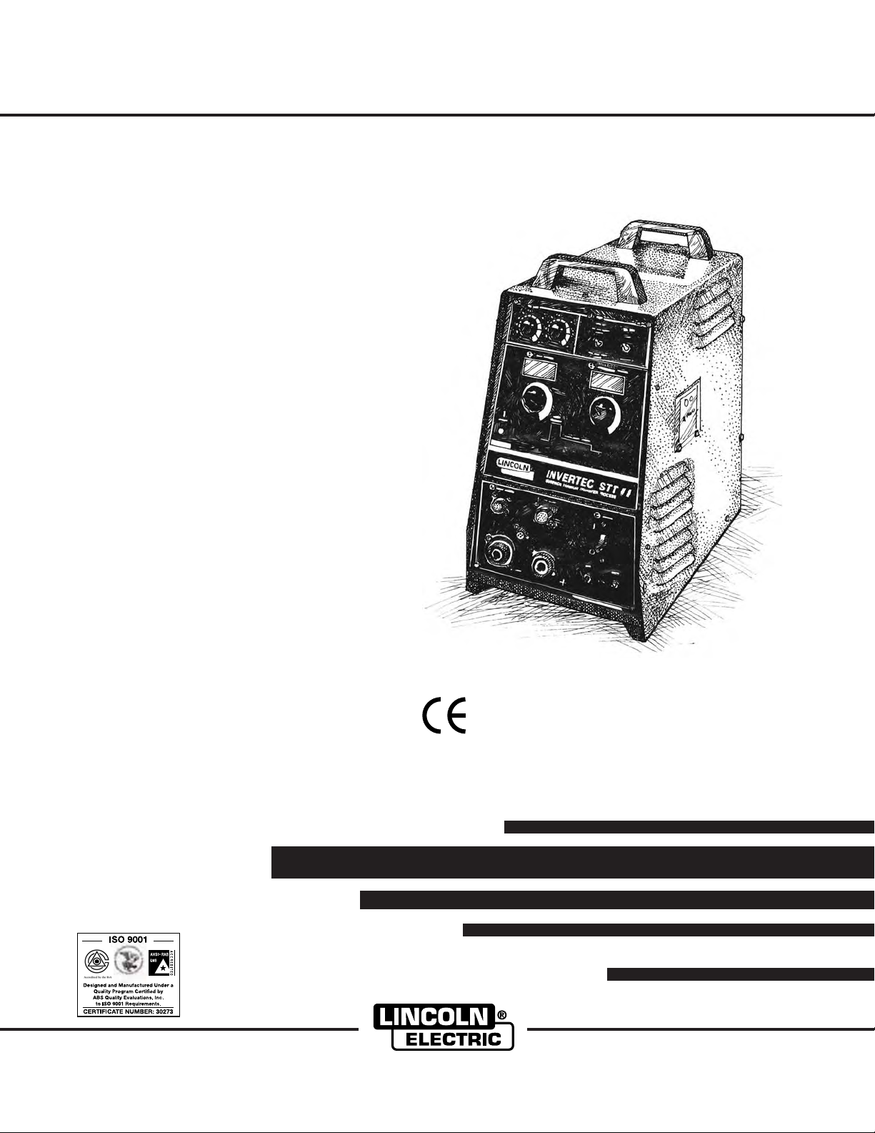
INVERTEC
RETURN TO MAIN MENU
®
S T T
®
II (CE)
IM904
July, 2006
For use with machines having Code Numbers:
Safety Depends on You
Lincoln arc welding and cutting
equipment is designed and built
with safety in mind. However,
your overall safety can be
increased by proper installation
... and thoughtful operation on
your part. DO NOT INSTALL,
OPERATE OR REPAIR THIS
EQUIPMENT WITHOUT READING THIS MANUAL AND THE
SAFETY PRECAUTIONS CONTAINED THROUGHOUT. And,
most importantly, think before
you act and be careful.
11366, 11367
Cleveland, Ohio 44117-1199 U.S.A. TEL: 216.481.8100 FAX: 216.486.1751 WEB SITE: www.lincolnelectric.com
ISO/IEC 60974-1
OPERATOR’S MANUAL
Copyright © 2006 Lincoln Global Inc.
• World's Leader in Welding and Cutting Products •
• Sales and Service through Subsidiaries and Distributors Worldwide •
Page 2
i
SAFETY
i
WARNING
CALIFORNIA PROPOSITION 65 WARNINGS
Diesel engine exhaust and some of its constituents
are known to the State of California to cause cancer, birth defects, and other reproductive harm.
The Above For Diesel Engines
ARC WELDING CAN BE HAZARDOUS. PROTECT YOURSELF AND OTHERS FROM POSSIBLE SERIOUS INJURY OR DEATH.
KEEP CHILDREN AWAY. PACEMAKER WEARERS SHOULD CONSULT WITH THEIR DOCTOR BEFORE OPERATING.
Read and understand the following safety highlights. For additional safety information, it is strongly recommended that you
purchase a copy of “Safety in Welding & Cutting - ANSI Standard Z49.1” from the American Welding Society, P.O. Box
351040, Miami, Florida 33135 or CSA Standard W117.2-1974. A Free copy of “Arc Welding Safety” booklet E205 is available
from the Lincoln Electric Company, 22801 St. Clair Avenue, Cleveland, Ohio 44117-1199.
BE SURE THAT ALL INSTALLATION, OPERATION, MAINTENANCE AND REPAIR PROCEDURES ARE
PERFORMED ONLY BY QUALIFIED INDIVIDUALS.
The engine exhaust from this product contains
chemicals known to the State of California to cause
cancer, birth defects, or other reproductive harm.
The Above For Gasoline Engines
FOR ENGINE
powered equipment.
1.a. Turn the engine off before troubleshooting and maintenance
work unless the maintenance work requires it to be running.
____________________________________________________
1.b. Operate engines in open, well-ventilated
areas or vent the engine exhaust fumes
outdoors.
____________________________________________________
1.c. Do not add the fuel near an open flame
welding arc or when the engine is running.
Stop the engine and allow it to cool before
refueling to prevent spilled fuel from vaporizing on contact with hot engine parts and
igniting. Do not spill fuel when filling tank. If
fuel is spilled, wipe it up and do not start
engine until fumes have been eliminated.
____________________________________________________
1.d. Keep all equipment safety guards, covers and devices in
position and in good repair.Keep hands, hair, clothing and
tools away from V-belts, gears, fans and all other moving
parts when starting, operating or repairing equipment.
____________________________________________________
1.e. In some cases it may be necessary to remove safety
guards to perform required maintenance. Remove
guards only when necessary and replace them when the
maintenance requiring their removal is complete.
Always use the greatest care when working near moving
parts.
___________________________________________________
1.f. Do not put your hands near the engine fan.
Do not attempt to override the governor or
idler by pushing on the throttle control rods
while the engine is running.
1.h. To avoid scalding, do not remove the
radiator pressure cap when the engine is
hot.
ELECTRIC AND
MAGNETIC FIELDS
may be dangerous
2.a. Electric current flowing through any conductor causes
localized Electric and Magnetic Fields (EMF). Welding
current creates EMF fields around welding cables and
welding machines
2.b. EMF fields may interfere with some pacemakers, and
welders having a pacemaker should consult their physician
before welding.
2.c. Exposure to EMF fields in welding may have other health
effects which are now not known.
2.d. All welders should use the following procedures in order to
minimize exposure to EMF fields from the welding circuit:
2.d.1.
Route the electrode and work cables together - Secure
them with tape when possible.
2.d.2. Never coil the electrode lead around your body.
2.d.3. Do not place your body between the electrode and
work cables. If the electrode cable is on your right
side, the work cable should also be on your right side.
___________________________________________________
1.g. To prevent accidentally starting gasoline engines while
turning the engine or welding generator during maintenance
work, disconnect the spark plug wires, distributor cap or
magneto wire as appropriate.
2.d.4. Connect the work cable to the workpiece as close as
possible to the area being welded.
2.d.5. Do not work next to welding power source.
Mar ‘95
Page 3
ii
SAFETY
ii
ELECTRIC SHOCK can
kill.
3.a. The electrode and work (or ground) circuits
are electrically “hot” when the welder is on.
Do not touch these “hot” parts with your bare
skin or wet clothing. Wear dry, hole-free
gloves to insulate hands.
3.b. Insulate yourself from work and ground using dry insulation.
Make certain the insulation is large enough to cover your full
area of physical contact with work and ground.
In addition to the normal safety precautions, if welding
must be performed under electrically hazardous
conditions (in damp locations or while wearing wet
clothing; on metal structures such as floors, gratings or
scaffolds; when in cramped positions such as sitting,
kneeling or lying, if there is a high risk of unavoidable or
accidental contact with the workpiece or ground) use
the following equipment:
• Semiautomatic DC Constant Voltage (Wire) Welder.
• DC Manual (Stick) Welder.
• AC Welder with Reduced Voltage Control.
3.c. In semiautomatic or automatic wire welding, the electrode,
electrode reel, welding head, nozzle or semiautomatic
welding gun are also electrically “hot”.
3.d. Always be sure the work cable makes a good electrical
connection with the metal being welded. The connection
should be as close as possible to the area being welded.
3.e. Ground the work or metal to be welded to a good electrical
(earth) ground.
3.f.
Maintain the electrode holder, work clamp, welding cable and
welding machine in good, safe operating condition. Replace
damaged insulation.
3.g. Never dip the electrode in water for cooling.
3.h. Never simultaneously touch electrically “hot” parts of
electrode holders connected to two welders because voltage
between the two can be the total of the open circuit voltage
of both welders.
3.i. When working above floor level, use a safety belt to protect
yourself from a fall should you get a shock.
3.j. Also see Items 6.c. and 8.
ARC RAYS can burn.
4.a. Use a shield with the proper filter and cover
plates to protect your eyes from sparks and
the rays of the arc when welding or observing
open arc welding. Headshield and filter lens
should conform to ANSI Z87. I standards.
4.b. Use suitable clothing made from durable flame-resistant
material to protect your skin and that of your helpers from
the arc rays.
4.c. Protect other nearby personnel with suitable, non-flammable
screening and/or warn them not to watch the arc nor expose
themselves to the arc rays or to hot spatter or metal.
FUMES AND GASES
can be dangerous.
5.a. Welding may produce fumes and gases
hazardous to health. Avoid breathing these
fumes and gases.When welding, keep
your head out of the fume. Use enough
ventilation and/or exhaust at the arc to keep
fumes and gases away from the breathing zone. When
welding with electrodes which require special
ventilation such as stainless or hard facing (see
instructions on container or MSDS) or on lead or
cadmium plated steel and other metals or coatings
which produce highly toxic fumes, keep exposure as
low as possible and below Threshold Limit Values (TLV)
using local exhaust or mechanical ventilation. In
confined spaces or in some circumstances, outdoors, a
respirator may be required. Additional precautions are
also required when welding on galvanized steel.
5. b. The operation of welding fume control equipment is affected
by various factors including proper use and positioning of
the equipment, maintenance of the equipment and the specific welding procedure and application involved. Worker
exposure level should be checked upon installation and
periodically thereafter to be certain it is within applicable
OSHA PEL and ACGIH TLV limits.
5.c.
Do not weld in locations near chlorinated hydrocarbon
coming from degreasing, cleaning or spraying operations.
The heat and rays of the arc can react with solvent vapors
form phosgene, a highly toxic gas, and other irritating products.
5.d. Shielding gases used for arc welding can displace air and
cause injury or death. Always use enough ventilation,
especially in confined areas, to insure breathing air is safe.
vapors
to
5.e. Read and understand the manufacturer’s instructions for this
equipment and the consumables to be used, including the
material safety data sheet (MSDS) and follow your
employer’s safety practices. MSDS forms are available from
your welding distributor or from the manufacturer.
5.f. Also see item 1.b.
AUG 06
Page 4
iii
SAFETY
iii
WELDING SPARKS can
cause fire or explosion.
6.a.
Remove fire hazards from the welding area.
If this is not possible, cover them to prevent
the welding sparks from starting a fire.
materials from welding can easily go through small cracks
and openings to adjacent areas. Avoid welding near
hydraulic lines. Have a fire extinguisher readily available.
6.b. Where compressed gases are to be used at the job site,
special precautions should be used to prevent hazardous
situations. Refer to “Safety in Welding and Cutting” (ANSI
Standard Z49.1) and the operating information for the
equipment being used.
6.c. When not welding, make certain no part of the electrode
circuit is touching the work or ground. Accidental contact
can cause overheating and create a fire hazard.
6.d. Do not heat, cut or weld tanks, drums or containers until the
proper steps have been taken to insure that such procedures
will not cause flammable or toxic vapors from substances
inside. They can cause an explosion even
been “cleaned”. For information, purchase “Recommended
Safe Practices for the
Containers and Piping That Have Held Hazardous
Substances”, AWS F4.1 from the American Welding Society
(see address above).
6.e. Vent hollow castings or containers before heating, cutting or
welding. They may explode.
Sparks and spatter are thrown from the welding arc. Wear oil
6.f.
free protective garments such as leather gloves, heavy shirt,
cuffless trousers, high shoes and a cap over your hair. Wear
ear plugs when welding out of position or in confined places.
Always wear safety glasses with side shields when in a
welding area.
6.g. Connect the work cable to the work as close to the welding
area as practical. Work cables connected to the building
framework or other locations away from the welding area
increase the possibility of the welding current passing
through lifting chains, crane cables or other alternate circuits. This can create fire hazards or overheat lifting chains
or cables until they fail.
6.h. Also see item 1.c.
Remember that welding sparks and hot
though
they have
Preparation
for Welding and Cutting of
CYLINDER may explode
if damaged.
7.a. Use only compressed gas cylinders
containing the correct shielding gas for the
process used and properly operating
regulators designed for the gas and
pressure used. All hoses, fittings, etc. should be suitable for
the application and maintained in good condition.
7.b. Always keep cylinders in an upright position securely
chained to an undercarriage or fixed support.
7.c. Cylinders should be located:
• Away from areas where they may be struck or subjected to
physical damage.
• A safe distance from arc welding or cutting operations and
any other source of heat, sparks, or flame.
7.d. Never allow the electrode, electrode holder or any other
electrically “hot” parts to touch a cylinder.
7.e. Keep your head and face away from the cylinder valve outlet
when opening the cylinder valve.
7.f. Valve protection caps should always be in place and hand
tight except when the cylinder is in use or connected for
use.
7.g. Read and follow the instructions on compressed gas
cylinders, associated equipment, and CGA publication P-l,
“Precautions for Safe Handling of Compressed Gases in
Cylinders,” available from the Compressed Gas Association
1235 Jefferson Davis Highway, Arlington, VA 22202.
FOR ELECTRICALLY
powered equipment.
8.a. Turn off input power using the disconnect
switch at the fuse box before working on
the equipment.
8.b. Install equipment in accordance with the U.S. National
Electrical Code, all local codes and the manufacturer’s
recommendations.
8.c. Ground the equipment in accordance with the U.S. National
Electrical Code and the manufacturer’s recommendations.
Mar ‘95
Page 5

iv
SAFETY
iv
PRÉCAUTIONS DE SÛRETÉ
Pour votre propre protection lire et observer toutes les instructions
et les précautions de sûreté specifiques qui parraissent dans ce
manuel aussi bien que les précautions de sûreté générales suivantes:
Sûreté Pour Soudage A L’Arc
1. Protegez-vous contre la secousse électrique:
a. Les circuits à l’électrode et à la piéce sont sous tension
quand la machine à souder est en marche. Eviter toujours
tout contact entre les parties sous tension et la peau nue
ou les vétements mouillés. Porter des gants secs et sans
trous pour isoler les mains.
b. Faire trés attention de bien s’isoler de la masse quand on
soude dans des endroits humides, ou sur un plancher
metallique ou des grilles metalliques, principalement dans
les positions assis ou couché pour lesquelles une grande
partie du corps peut être en contact avec la masse.
c. Maintenir le porte-électrode, la pince de masse, le câble
de soudage et la machine à souder en bon et sûr état
defonctionnement.
d.Ne jamais plonger le porte-électrode dans l’eau pour le
refroidir.
e. Ne jamais toucher simultanément les parties sous tension
des porte-électrodes connectés à deux machines à souder
parce que la tension entre les deux pinces peut être le
total de la tension à vide des deux machines.
f. Si on utilise la machine à souder comme une source de
courant pour soudage semi-automatique, ces precautions
pour le porte-électrode s’applicuent aussi au pistolet de
soudage.
2. Dans le cas de travail au dessus du niveau du sol, se protéger
contre les chutes dans le cas ou on recoit un choc. Ne jamais
enrouler le câble-électrode autour de n’importe quelle partie
du corps.
5. Toujours porter des lunettes de sécurité dans la zone de
soudage. Utiliser des lunettes avec écrans lateraux dans les
zones où l’on pique le laitier.
6. Eloigner les matériaux inflammables ou les recouvrir afin de
prévenir tout risque d’incendie dû aux étincelles.
7. Quand on ne soude pas, poser la pince à une endroit isolé de
la masse. Un court-circuit accidental peut provoquer un
échauffement et un risque d’incendie.
8. S’assurer que la masse est connectée le plus prés possible
de la zone de travail qu’il est pratique de le faire. Si on place
la masse sur la charpente de la construction ou d’autres
endroits éloignés de la zone de travail, on augmente le risque
de voir passer le courant de soudage par les chaines de levage, câbles de grue, ou autres circuits. Cela peut provoquer
des risques d’incendie ou d’echauffement des chaines et des
câbles jusqu’à ce qu’ils se rompent.
9. Assurer une ventilation suffisante dans la zone de soudage.
Ceci est particuliérement important pour le soudage de tôles
galvanisées plombées, ou cadmiées ou tout autre métal qui
produit des fumeés toxiques.
10. Ne pas souder en présence de vapeurs de chlore provenant
d’opérations de dégraissage, nettoyage ou pistolage. La
chaleur ou les rayons de l’arc peuvent réagir avec les vapeurs
du solvant pour produire du phosgéne (gas fortement toxique)
ou autres produits irritants.
11. Pour obtenir de plus amples renseignements sur la sûreté,
voir le code “Code for safety in welding and cutting” CSA
Standard W 117.2-1974.
PRÉCAUTIONS DE SÛRETÉ POUR
3. Un coup d’arc peut être plus sévère qu’un coup de soliel,
donc:
a. Utiliser un bon masque avec un verre filtrant approprié
ainsi qu’un verre blanc afin de se protéger les yeux du rayonnement de l’arc et des projections quand on soude ou
quand on regarde l’arc.
b. Porter des vêtements convenables afin de protéger la
peau de soudeur et des aides contre le rayonnement de
l‘arc.
c. Protéger l’autre personnel travaillant à proximité au
soudage à l’aide d’écrans appropriés et non-inflammables.
4. Des gouttes de laitier en fusion sont émises de l’arc de
soudage. Se protéger avec des vêtements de protection libres
de l’huile, tels que les gants en cuir, chemise épaisse, pantalons sans revers, et chaussures montantes.
LES MACHINES À SOUDER À
TRANSFORMATEUR ET À
REDRESSEUR
1. Relier à la terre le chassis du poste conformement au code de
l’électricité et aux recommendations du fabricant. Le dispositif
de montage ou la piece à souder doit être branché à une
bonne mise à la terre.
2. Autant que possible, I’installation et l’entretien du poste seront
effectués par un électricien qualifié.
3. Avant de faires des travaux à l’interieur de poste, la debrancher à l’interrupteur à la boite de fusibles.
4. Garder tous les couvercles et dispositifs de sûreté à leur
place.
Mar. ‘93
Page 6
for selecting a QUALITY product by Lincoln Electric. We want you
Thank You
to take pride in operating this Lincoln Electric Company product
••• as much pride as we have in bringing this product to you!
Please Examine Carton and Equipment For Damage Immediately
When this equipment is shipped, title passes to the purchaser upon receipt by the carrier. Consequently, Claims
for material damaged in shipment must be made by the purchaser against the transportation company at the
time the shipment is received.
Please record your equipment identification information below for future reference. This information can be
found on your machine nameplate.
Product _________________________________________________________________________________
Model Number ___________________________________________________________________________
Code Number or Date Code_________________________________________________________________
Serial Number____________________________________________________________________________
Date Purchased___________________________________________________________________________
vv
Where Purchased_________________________________________________________________________
Whenever you request replacement parts or information on this equipment, always supply the information you
have recorded above. The code number is especially important when identifying the correct replacement parts.
On-Line Product Registration
- Register your machine with Lincoln Electric either via fax or over the Internet.
• For faxing: Complete the form on the back of the warranty statement included in the literature packet
accompanying this machine and fax the form per the instructions printed on it.
• For On-Line Registration: Go to our
“Product Registration”. Please complete the form and submit your registration.
Read this Operators Manual completely before attempting to use this equipment. Save this manual and keep it
handy for quick reference. Pay particular attention to the safety instructions we have provided for your protection.
The level of seriousness to be applied to each is explained below:
WEB SITE at www.lincolnelectric.com. Choose “Quick Links” and then
WARNING
This statement appears where the information must be followed exactly to avoid serious personal injury or
loss of life.
CAUTION
This statement appears where the information must be followed to avoid minor personal injury or damage to
this equipment.
Page 7

vi
vi
TABLE OF CONTENTS
Page
Safety .....................................................................................................................i-iv
Installation ......................................................................................................Section A
Technical Specifications.....................................................................................A-1,A-2
Location ....................................................................................................................A-3
Stacking ....................................................................................................................A-3
Tilting .....................................................................................................................A-3
Machine Grounding and High Frequency Interference Protection............................A-3
Input Connections .....................................................................................................A-3
Supply Connections ...........................................................................................A-3
Input Cable Installation and Connection.............................................................A-4
Ground Connection ............................................................................................A-4
Input Voltage Reconnect Procedure .........................................................................A-5
Output Connections ..................................................................................................A-5
Wire Feeder Output Connections.......................................................................A-5
Operation ........................................................................................................Section B
Safety Precautions....................................................................................................B-1
General Description ..................................................................................................B-2
Recommended Equipment .......................................................................................B-2
Operating Controls....................................................................................................B-2
Design Features and Advantages.............................................................................B-2
Welding Capability ....................................................................................................B-2
Limitations.................................................................................................................B-2
Operational Features and Controls...........................................................................B-3
Welding Operation ....................................................................................................B-4
Welding Parameters and Guidelines ........................................................................B-5
Welding Procedures for (Steel) Horizontal Fillet .......................................................B-5
Welding Procedures for (Stainless Steel) Horizontal Fillet .......................................B-6
Accessories ....................................................................................................Section C
Options/Accessories .................................................................................................C-1
LN-742 or STT-10 Wire Feeder Connection Instructions .........................................C-1
Maintenance....................................................................................................Section D
Safety Precautions .................................................................................................D-1
Input Filter Capacitor Discharge Procedure ...........................................................D-1
Preventive Maintenance.........................................................................................D-2
Troubleshooting .............................................................................................Section E
How To Use Troubleshooting Guide ......................................................................E-1
Troubleshooting Guide ..................................................................................E-2 - E-6
Diagrams .........................................................................................................Section F
Wiring Diagram............................................................................................F-1 thru F-3
Dimension Print.........................................................................................................F-4
Parts List ....................................................................................................P-540 Series
Page 8
A-1
INSTALLATION
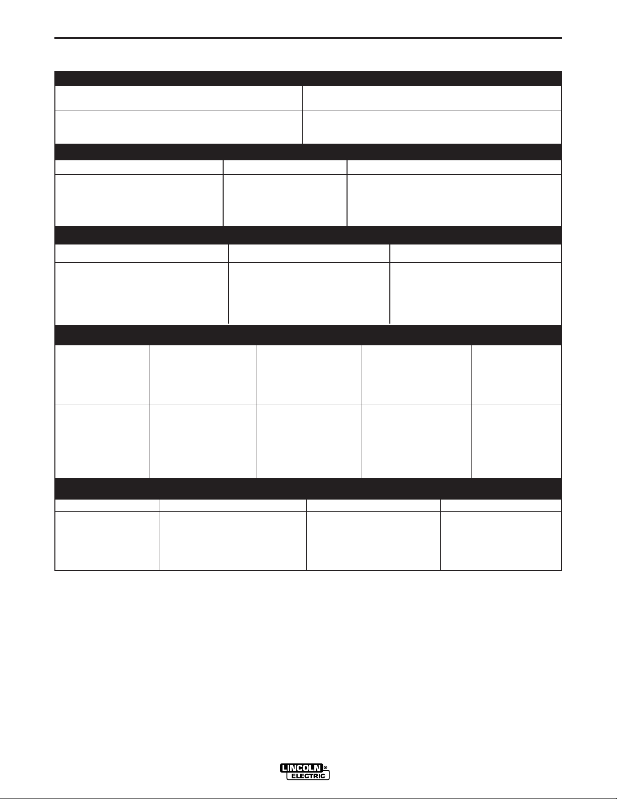
TECHNICAL SPECIFICATIONS –INVERTEC STT II (CE) (For Code 11366)
INPUT- THREE PHASE ONLY
STANDARD VOLTAGE INPUT CURRENT AT RATED OUTPUT
200/220/380/415/440/3/50/60 HZ 33/30/18/17/16
RATED OUTPUT
DUTY CYCLE AMPS VOLTS AT RATED AMPS
60% Duty Cycle 225 29
100% Duty Cycle 200 28
OUTPUT
CURRENT RANGE OPEN CIRCUIT VOLTAGE AUXILIARY POWER
A-1
Peak Current
1
0 - 450 Amps 85 VDC Maximum 1152VAC @ 4 Amps
Background 0 - 125 Amps 42 VAC @ 4 Amps
RECOMMENDED INPUT WIRE AND FUSE SIZES
INPUT VOLTAGE FUSE(SUPER LAG) INPUT AMPERE TYPE 75°C TYPE 75°C
AND FREQUENCY OR BREAKER RATING ON COPPER COPPER
SIZE NAMEPLATE SUPPLY WIRE GROUND WIRE
IN CONDUIT IN CONDUIT
AWG (IEC) SIZES
200/50/60 40 33
220/50/60 40 30 10 (6 mm2) 10 (6 mm2)
380/50/60 30 18
415/50/60 30 17
440/50/60 30 16
AWG (IEC) SIZES
PHYSICAL DIMENSIONS
HEIGHT WIDTH DEPTH WEIGHT
23.2 in 13.2 in. 24.4 in. 100 lbs.
589 mm 336 mm 620 mm 46 kg
1
At low input voltages (below 208 VAC) and input voltages of 380 VAC through 415 VAC there may be a 15% reduction in Peak Current.
2
115 VAC not present on European Models.
INVERTEC STT II (CE)
Page 9
A-2
INSTALLATION
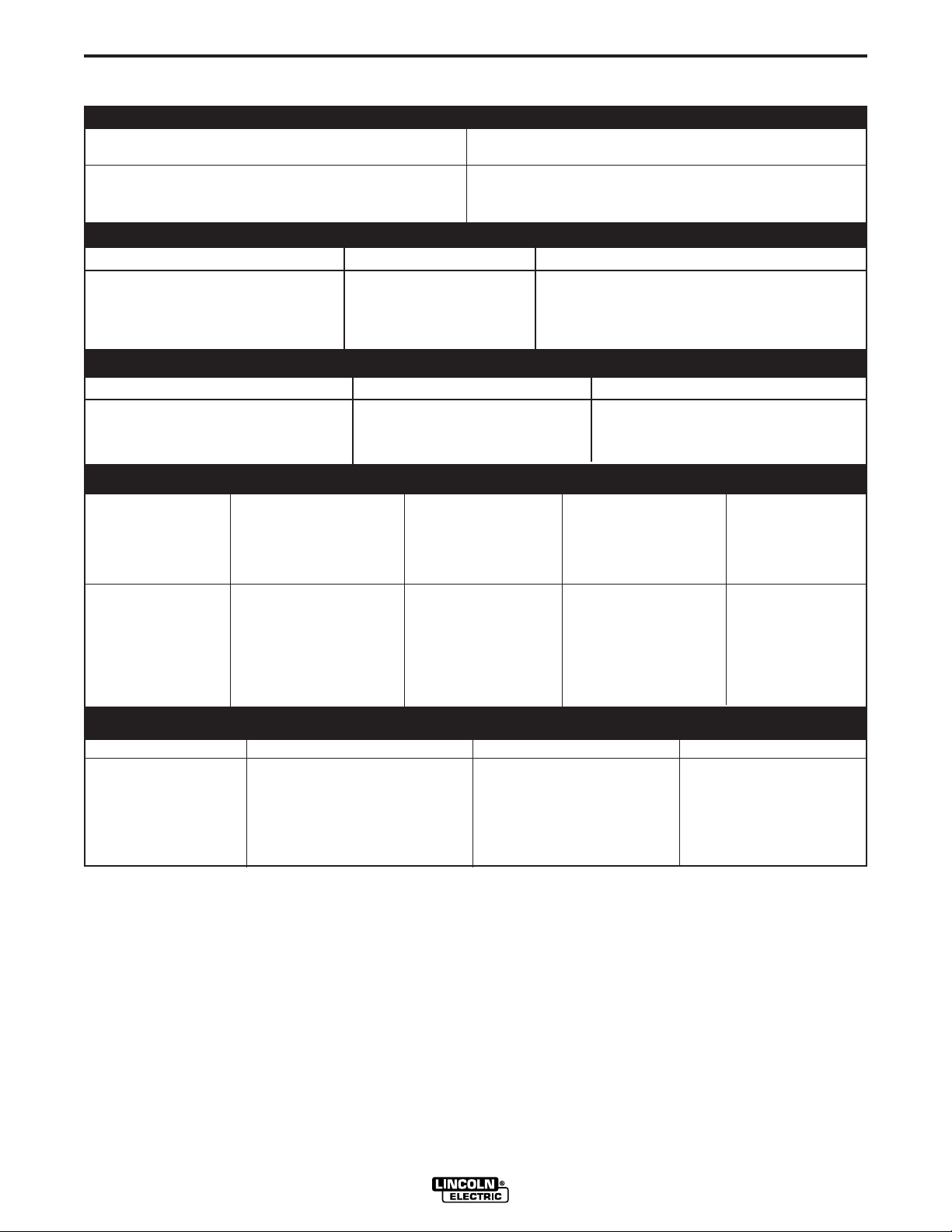
TECHNICAL SPECIFICATIONS –INVERTEC STT II (CE) (For Code 11367)
INPUT- THREE PHASE ONLY
STANDARD VOLTAGE INPUT CURRENT AT RATED OUTPUT
200/208/380/400/415/3/50/60 HZ 36/34/20/19/18
RATED OUTPUT
DUTY CYCLE AMPS VOLTS AT RATED AMPS
60% Duty Cycle 225 29
100% Duty Cycle 200 28
OUTPUT
CURRENT RANGE OPEN CIRCUIT VOLTAGE AUXILIARY POWER
A-2
Peak Current 0 - 450 Amps 88 VDC Maximum 115
Background 0 - 125 Amps 42 VAC @ 4 Amps
1
VAC @ 4 Amps
RECOMMENDED INPUT WIRE AND FUSE SIZES
INPUT VOLTAGE FUSE(SUPER LAG) INPUT AMPERE TYPE 75°C TYPE 75°C
AND FREQUENCY OR BREAKER RATING ON COPPER COPPER
SIZE NAMEPLATE SUPPLY WIRE GROUND WIRE
IN CONDUIT IN CONDUIT
AWG (IEC) SIZES
200/50/60 40 36
208/50/60 40 34
380/50/60 30 20 10 (6 mm2) 10 (6 mm2)
400/50/60 30 19
415/50/60 30 18
AWG (IEC) SIZES
PHYSICAL DIMENSIONS
HEIGHT WIDTH DEPTH WEIGHT
23.2 in 13.2 in. 24.4 in. 100 lbs.
589 mm 336 mm 620 mm 46 kg
1
115 VAC not present on European Models.
INVERTEC STT II (CE)
Page 10

A-3
Read and understand entire Installation Section
before starting installation.
INSTALLATION
WARNING
ELECTRIC SHOCK can kill.
• Only qualified personnel should
perform this installation.
• Turn the input power OFF at the
disconnect switch or fuse box
before installing this
equipment.
• Turn the power switch on the Invertec
STT “OFF” before connecting or disconnecting input power lines, output cables,
or control cables.
• Do not touch electrically hot
parts.
• Always connect the ground terminal to a
good electrical earth ground.
SELECT SUITABLE LOCATION
Locate the machine where there is free circulation of
clean air. Place the machine so that air can freely circulate into the sides and out of the rear of the
machine. Dirt and dust that can be drawn into the
machine should be kept to a minimum. Failure to
observe these precautions can result in excessive
operating temperatures and nuisance shut down of
the INVERTEC STT II (CE).
This machine carries an enclosure rating of IP21S. It
should not be placed in extremely damp or dirty locations. It should not be exposed to rain or snow.
A-3
MACHINE GROUNDING AND HIGH
FREQUENCY INTERFERENCE
PROTECTION
The machine may not be suitable for use in an environment where high frequency is present. For example do not place the machine in close proximity to
“TIG” or “PLASMA” operations. To minimize high frequency interference:
Locate the STT II power source more than 15
feet (4.5 m) away from high frequency units
and more than 25 feet (7.6 m) separation
between ground connections or welding arcs
of high frequency units.
Provide proper electrical ground to the
machine per local and national electrical
codes.
INPUT CONNECTIONS
FAILURE TO FOLLOW THESE INSTRUCTIONS
CAN CAUSE IMMEDIATE FAILURE OF COMPONENTS WITHIN THE WELDER.
Turn the input power off at the disconnect switch
before attempting to connect the input power lines.
Connect the green lead of the power cord to ground
per local and national electrical codes.
SUPPLY CONNECTIONS
STACKING
The INVERTEC STT II (CE) cannot be stacked.
TILTING
Place the machine on a secure, level surface otherwise the unit may topple over.
INVERTEC STT II (CE)
Be sure the voltage, phase, and frequency of the input
supply is as specified on the rating plate. Input Power
supply line entry in provided on the case back of the
machine. See figure A.1 for location of the rating plate.
The INVERTEC STT II (CE) should be connected only
by a qualified electrician. Installation should be made
in accordance with local and national codes. Refer to
the “Technical Specifications” at the beginning of this
section for proper fuse sizes, ground wire, and input
supply power cable sizes.
Some models come from the factory with an input
power cord. If your model does not include the input
power cord install the proper size input cable and
ground cable according to “INPUT CABLE INSTALLATION AND CONNECTION”.
Page 11
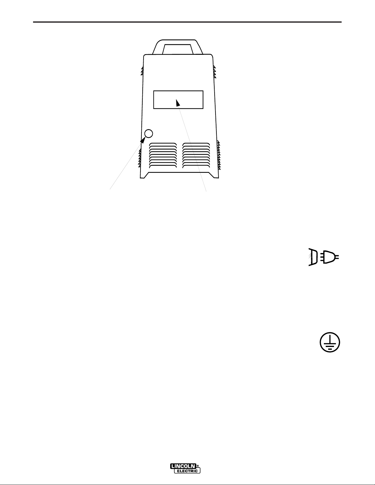
A-4
CASE BACK
RATING PLATE
INPUT CABLE
ENTRY ACCESS
& CABLE STRAIN RELIEF
INSTALLATION
A-4
FIGURE A.1 CASE BACK
INPUT CABLE INSTALLATION AND CONNECTION
A cable strain relief is provided at the supply line entry
and is designed to accommodate cable diameters of
.310 - 1.070 in. (7.9 - 27.2 mm). On European models
the strain relief is designed to accommodate cable
diameters of .709 - 1.000 in. (18.0 - 25.4 mm). Refer
to “Technical Specifications” at the beginning of this
section for the proper input cable sizes. Refer to
Figure A.1 and perform the following steps:
1. Remove the wraparound cover of the
INVERTEC STT II (CE).
2. Feed the input cable through the input cable
entry access hole at the right rear of the
machine.
3. Route the cable through the cable hangers,
located along the lower right inside edge of
the machine, up to the power switch located
on the front panel.
5. Connect the three phase line conductors to the power switch terminals labeled U, V and W. Tighten
the connections to 3.0 Nm. (27 in.-lb.) torque.
6. Securely tighten the cable strain relief located
on the case back of the machine.
GROUND CONNECTION
1. Connect the ground terminal to earth
ground per National Electrical Code.
2. Replace the wraparound cover of the
INVERTEC STT II (CE).
4. Strip away 102 mm (4 in.) of the outer jacket.
Trim fillers and strip conductor jackets to
connect to the power switch.
INVERTEC STT II (CE)
Page 12
A-5
4A
380-415
OR
OR
200-208
*
*
*
(NOT PRESENT ON ALL MODELS)
ACCESS DOOR
LOCATION
INSTALLATION
380 or 415 VAC 1. Open reconnect panel
(Codes 11366) access door on wraparound.
380,400 or 415 VAC 1. Open reconnect panel
(Codes 11367) access door on wraparound.
A-5
2. Move input voltage switch
to Voltage = 380-460V
position.
3. Move lead “A” to 380-415
Terminal.
2. Move input voltage switch
to Voltage = 380-415V
position.
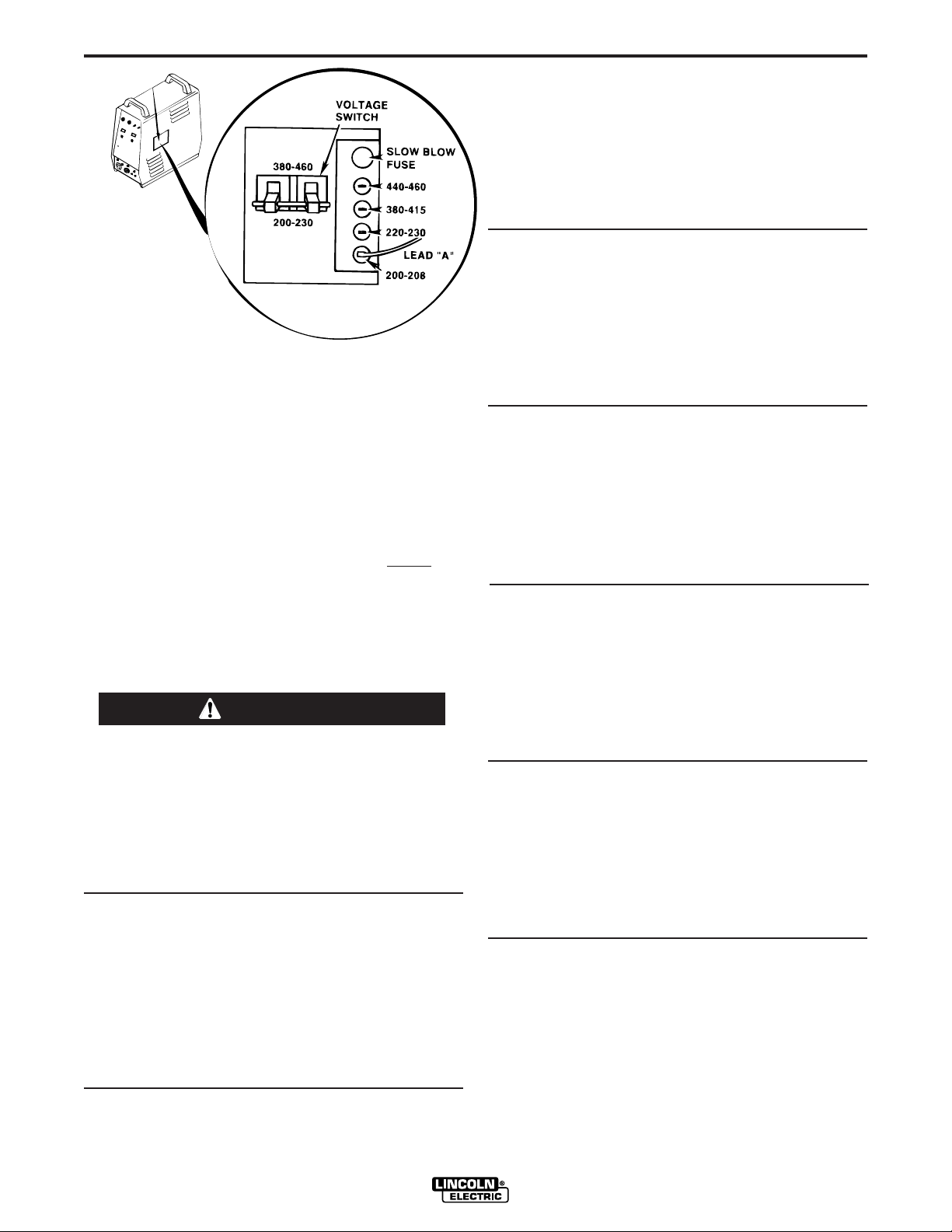
FIGURE A.2 RECONNECT P ANEL
I
NPUT VOLTAGE RECONNECT
PROCEDURE
As shipped from the factory, multiple voltage
machines are internally configured for the highest
input voltage (440-460 VAC), for Code 11366 and
(380-415 VAC), for Code 11367.
1. For Connections to 440 or 460 VAC verify
the
internal configurations to the procedures shown
below and refer to Figure A.2.
2. For Connections to 200,208,220,230,380,400 or
415 VAC follow the procedure shown below and
refer to figure A.2.
WARNING
NOTE: Turn main power to the machine OFF
before performing the reconnect procedure.
Failure to do so will result in damage to the
machine. DO NOT switch the reconnect bar with
machine power ON.
------------------------------------------------------------------------
To Operate at Procedure
460 or 440 VAC 1. Open reconnect panel
(Code 11366) access door on wraparound.
2. Move input voltage switch
to Voltage = 380-460V position.
3. Move lead “A” to 440-460
Terminal.
3. Move lead “A” to 380-415
Terminal.
220 or 230 VAC 1. Open reconnect panel
(Codes 11366) access door on wraparound.
2. Move input voltage switch
to Voltage = 200 -230V
position.
3. Move lead “A” to 220-230
Terminal.
200 or 208 VAC 1. Open reconnect panel
(Codes 11366) access door on wraparound.
2. Move input voltage switch
to Voltage = 200 -230V
position.
3. Move lead “A” to 200-208
Terminal.
200 or 208 VAC 1. Open reconnect panel
(Codes 11367) access door on wraparound.
2. Move input voltage switch
to Voltage = 200 -230V
position.
3. Move lead “A” to 200-208
Terminal.
OUTPUT CONNECTIONS
WIRE FEEDER OUTPUT CONNECTIONS
Refer to the Accessories section of this manual for instructions
on connecting a wire feeder to the INVERTEC STT II (CE).
The LN-742 or STT-10 wire feeder is the recommended feeder
for use with the INVERTEC STT II (CE).
INVERTEC STT II (CE)
Page 13

B-1
OPERATION
OPERATING INSTRUCTIONS
Read and understand entire section before
operating machine.
GENERAL WARNINGS
SAFETY PRECAUTIONS
WARNING
ELECTRIC SHOCK
can kill.
• Do not touch electrically live parts
or electrode with skin or wet
clothing.
• Insulate yourself from work and
ground.
B-1
• Always wear dry insulating
gloves.
FUMES AND GASES
can be dangerous.
• Keep your head out of fumes.
• Use ventilation or exhaust to
remove fumes from breathing
zone.
WELDING SPARKS
can cause fire or
explosion
• Keep flammable material away.
• Do not weld on containers that
have held combustibles.
ARC RAYS
can burn.
• Wear eye, ear and body
protection.
Observe additional Safety Guidelines detailed in the beginning of this manual.
INVERTEC STT II (CE)
Page 14

B-2
GENERAL DESCRIPTION
OPERATION
• High temperature Class H insulation.
B-2
The INVERTEC STT II (CE) is a 225-ampere inverter
based arc welding power source specifically designed
for the STT welding process. It is neither a constant
current (CC) nor a constant voltage (CV) machine. It
is a power source that delivers current of a desired
wave form and characteristics that are superior to conventional short circuiting GMAW. The process is optimized for short-circuiting GMAW welding.
RECOMMENDED EQUIPMENT
The LN-742 or STT-10 wire feeder is recommended
for use with the STT II. The LN-7 GMA, LN-9 GMA,
NA-5, and NA-5R can all be used with the STT II.
However, these units can only be used to feed wire
since these feeders have no provision for control of
the STT output.
OPERATING CONTROLS
The INVERTEC STT II (CE) has the following controls
as standard: On/Off switch, Peak Current adjustment,
Background Current adjustment, Hot Start adjustment,
Tailout, and 2 toggle switches; one for wire size selection and one for wire type selection.
• Protection circuits and ample safety margins prevent
damage to the solid state components from transient voltages and high currents.
• Preset welding current capability.
• STT II offers improvements over the previous model.
Approximately 40% increase in deposition rate
capability, and a significant increase in travel speed.
WELDING CAPABILITY
The INVERTEC STT II (CE) is rated at 225 amps, 29
volts, at 60% duty cycle on a ten minute basis. It is
capable of higher duty cycles at lower output currents.
If the duty cycle(s) are exceeded, a thermal protector
will shut off the output until the machine cools to a reasonable operating temperature.
LIMITATIONS
• May not be suitable for use in an environment with
High Frequency present. (“See Machine Grounding
and High Frequency Protection” in the Installation
section of this manual)
• Suitable for indoor use only (IEC IP21S).
DESIGN FEATURES AND ADVANT AGES
• State of the art inverter technology yields high
power efficiency, excellent welding performance,
lightweight and compact design.
• Twist-Mate™ output terminals.
• Digital meters for procedure settings are standard.
• Automatic Inductance or Pinch Control.
• Solid state circuitry for extra long component life.
• Current feedback ensures that original procedure
settings all remain constant.
• Arc Sense lead assembly (Electrode and Work),
connects through a 4-pin case front connector.
• Peak Current and Background Current may be
remotely controlled.
• Thermostat and FET over current protector prevent
overheating from overloads, high ambient temperatures, or loss of air flow.
INVERTEC STT II (CE)
Page 15

B-3
4
1
2
3
7
6
8
10
9
11
14
15
12
13
5
OPERATION
B-3
OPERA TIONAL FEA TURES AND CONTROLS
All operator controls are located on the case front of the INVERTEC STT II (CE). Refer to Figure B.1 for locations.
FIGURE B.1 CASE FRONT CONTROLS
1. POWER SWITCH: Turns output
power ON and OFF. This switch
also controls auxiliary power
available through the 14-pin Wire
Feeder Receptacle.
2A. BACKGROUND CURRENT OUTPUT CON-
TROL: The output current is switched to
the Background level at the conclusion of
the preceding Peak Current pulse. This
knob allows preset adjustment of the
amplitude of the background current up
to 125 amperes.
2B. BACKGROUND CURRENT DISPLAY METER:
This is a digital meter for displaying the
preset Background Current. This meter
displays in 1 amp increments. This meter
does not indicate the actual welding current, only the preset current.
3A. PEAK CURRENT OUTPUT CONTROL:
The beginning portion of the welding arc is
a pulse of current referred to as Peak
Current. This knob allows preset adjustment of the amplitude of the peak current
up to 450 amperes.
V
3B. PEAK CURRENT DISPLAY METER: This
ON
OFF
A
INVERTEC STT II (CE)
is a digital meter for displaying the preset
Peak Current. This meter displays in 1
amp increments. This meter does not
indicate actual welding current only the
preset current.
4. HOT START CONTROL POTENTIOMETER:
“Hot Start” provides approximately 25% to
50% more current during the initial start of
the weld for improved arc starting and bead
appearance. This control adjusts the duration of this “Hot Start” current. The control range is
from 0 to 10, where 0 corresponds to the zero or no
“Hot Start”, and 10 is maximum for a “Hot Start”
lasting for about four (4) seconds.
5. TAILOUT: Alters the current waveform to increase
deposit rate and travel speed. The Minimum setting sets STT II to the original STT waveform. As
tailout is increased peak and Background current
may need to be reduced to maintain optimum performance.
A
Page 16

B-4
6. WIRE SIZE SELECT SWITCH: This toggle switch
selects between electrode diameters of .035” (1
mm) and smaller or .045” (1.2 mm) and larger. The
.035” (1 mm) position provides improved performance of smaller diameter wires at higher wire feed
speeds.
OPERATION
B-4
13. 115V AUXILIARY POWER CIRCUIT BREAKER
(Not on European Models): The 115 VAC
supply is protected from excessive current
draws with a 6 amp circuit breaker. When
the breaker “trips” its button will extend.
Depressing this button will reset the breaker.
7. WIRE TYPE SELECT SWITCH: This toggle switch
selects between mild or stainless steel. In the stainless position, the pulse width of the Peak Current is
changed from 1 to 2 ms for better performance for
stainless steel welding.
8. THERMAL SHUT-DOWN INDICATOR:
This light will indicate that either the internal
thermostat(s) or the FET over current sensor has actuated. Machine output will return after
the internal components have returned to normal
operating temperature (if the thermostat(s)
“opened”) or after about 3-7 seconds (if the FET
over current sensor activated).
REMOTE RECEPTACLE: This is a 10 pin MS-
9.
type connector for remote control of Peak Current
and Background Current. Trigger switch connections are also provided. The presence of the mating connector is automatically sensed, disabling the front panel Peak
and Background Current controls. Refer to “REMOTE CONTROL CONNECTOR” in the ACCESSORIES Section of this
manual for more information.
10. WIRE FEEDER RECEPTACLE: This is 14
pin MS-type connector for the wire feeder
connection. 115 and 42 VAC along with
the trigger switch connections are provided. (Only
42 VAC is available on European models). There
are no provisions for voltage control of the power
source by the wire feeder. Refer to the
Accessories section of this manual for wire feeder
connection instructions.
14. WORK TERMINAL: This twist-mate con-
nection is the negative output terminal for
connecting a work cable and clamp to the
workpiece.
15. ELECTRODE TERMINAL: This twist-
mate connection is the positive output terminal for connecting an electrode cable to
the wire feeder conductor block. Refer to
the Accessories Section for wire feeder connection
instructions.
WELDING OPERATION
Familiarize yourself with the controls on the
INVERTEC STT II (CE) before beginning to weld.
Familiarize yourself with the operating manual for the
wire feeder and the wire feeder controls before beginning to weld.
Set the Wire Size and Wire Type selection switches
per the appropriate wire. Refer to “Operational
Features and Controls” in this section for the function
of these switches.
11. ARC SENSE RECEPTACLE:
MS-type connector for WORK and ELECTRODE
sense leads. The STT requires a WORK sense
and ELECTRODE sense lead for proper operation.
The ELECTRODE sense lead is bolted together
with power source electrode lead at the wire feeder
gun block. The WORK sense lead is furnished with
an “alligator” type clip for connection to the work
piece. Refer to the LN 742 or STT-10 wire feeder
connection instructions in the Accessories section
of this manual for proper connection of these leads.
12. 42V AUXILIARY POWER CIRCUIT BREAKER:
The 42 VAC supply is protected from excessive current draws with a 6 amp circuit breaker. When the breaker “trips” its button will
extend. Depressing this button will reset the breaker.
This is a four pin
INVERTEC STT II (CE)
Page 17

B-5
OPERATION
WELDING PARAMETERS AND GUIDELINES
B-5
Adjusting this level to low will cause wire stubbing and
also poor wetting of the weld metal. This is similar to
a low voltage setting on a standard CV machine
The INVERTEC STT II (CE) is neither a constant current (CC) nor a constant voltage (CV) power source.
In general, wire diameter will be increased one size
compared to conventional (CV) power sources. The
larger the wire diameter the higher the deposition rate
(Up to 1/16”). Wire sizes below .035” are unnecessary
for most applications. The INVERTEC STT II (CE) is a
current controlled machine which is capable of changing the electrode current quickly in order to respond to
the instantaneous requirements of the arc and optimize performance. By sensing changes in welding
current, and hence the electrode state, the power
source will supply varying output currents to minimize
spatter. The Peak and Background currents are two
such current outputs that can be adjusted.
Wire Feed Speed controls the deposition rate. Peak
Current controls the Arc Length. Background Current
controls the Bead Contour. And Tailout increases
Power in the Arc.
PEAK CURRENT
The Peak Current control acts similar to an “arc pinch”
control. Peak current serves to establish the arc
length and promote good fusion. Higher peak current
levels will cause the arc to broaden momentarily while
increasing the arc length. If set too high, globular type
transfer will occur. Setting this level to low will cause
instability and wire stubbing. In practice, this current
level should be adjusted for minimum spatter and
puddle agitation.
Adjust Bead Shape
Note: Background Current levels for applications using
100% CO
gas blends with high percentages of Argon. This is a
result of the greater heat generated in the 100% CO2
arc. (100% CO2 is 35 volts/cm and 100% Argon is 20
volts/cm. 75% Argon, 25% CO2 is about 24 volts/cm.
Contact Tip
2 is less than similar procedures involving
to Work Distance
using Background Current
Adjust Arc Length
Note: In 100% CO2shielding gas applications the
peak current level should be set greater than in a cor-
responding application using a gas blend with a high
percentage of Argon. Longer initial arc lengths with
100% CO2are required to reduce spatter.
BACKGROUND CURRENT
The Background Current provides the control for the
overall heat input to the weld. Adjusting this level too
high will cause a large droplet to form and globular
type transfer to occur resulting in increased spatter.
with Peak Current
INVERTEC STT II (CE)
HOT START
The Hot Start control can be set to enhance establishing the arc and provide the capability of increasing the
heat at the start of the weld to compensate for a cold
work piece. Hot start adjusts the time that additional
current is applied during the starting of the arc. Refer
to “Operational Features and Controls” in this section
for a description of this control.
TAILOUT
The tail out provides additional heat without the molten
droplet becoming too large. Increase as necessary to
add “Heat” to the arc without increasing arc length.
(This will allow for faster travel speeds and produce
improved wetting). As tailout is increased, the peal
and/or background current is usually reduced.
WELDING ARC PERFORMANCE
For optimum spatter reduction, the arc should be concentrated on the puddle.
Page 18

B-6
45°
END VIEW
75°
FRONT VIEW
DIRECTION
OF
TRAVEL
75°
TOP VIEW
DIRECTION
OF
TRAVEL
45°
END VIEW
75°
FRONT VIEW
DIRECTION
OF
TRAVEL
75°
TOP VIEW
DIRECTION
OF
TRAVEL
OPERATION
B-6
WELDING PROCEDURES FOR STT II -
(Steel) Horizontal Fillet (See Table B.1 and B.2)
Table B.1
2
100% CO
Plate Thickness “ (mm) 20 ga 14 ga 10 ga
Electrode size “ (mm) 0.035 0.045 0.045
WFS “/min (m/min) 100 100 170
Peak Current 220 260 280
Background Current 30 40 65
Tailout setting 3 7 5
Average Amperage 60 105 120
Travel Speed “/min 12 12 12
Gas Flow cfh (L/min) 25 (12)
Electrical Stickout “ 1/4 - 3/8
75% CO
2
Plate Thickness “ (mm) 20 ga 14 ga 10 ga
Electrode size “ (mm) 0.035 0.045 0.045
WFS “/min (m/min) 100 100 120
Peak Current 225 270 310
Background Current 40 65 70
Tailout setting 8 4 6
Average Amperage 70 110 130
Travel Speed “/min 12 12 12
Gas Flow cfh (L/min) 25 (12)
Electrical Stickout “ 1/4 - 3/8
Gas Shield (Set for Steel Mode)
(0.9) (2.0) (3.25)
(0.9) (1.1) (1.1)
(2.5) (2.5) (4.2)
(m/min) (0.3) (0.3) (0.3)
(mm) (6.4 - 10)
Table B.2
- 25% Ar Gas Shield (Set for Steel Mode)
(0.9) (2.0) (3.25)
(0.9) (1.1) (1.1)
(2.5) (2.5) (3.0)
(m/min) (0.3) (0.3) (0.3)
(mm) (6.4 - 10)
(Stainless Steel) Horizontal Fillet
(See Table B.3 and B.4)
Table B.3
90% He, 7.5% Ar, 2.5% CO
2
Gas Shield (Set for Steel Mode)
Plate Thickness “ (mm) 20 ga 14 ga 10 ga
(0.9) (2.0) (3.25)
Electrode size “ (mm) 0.035 0.045 0.045
(0.9) (1.1) (1.1)
WFS “/min (m/min) 100 130 170
(2.5) (3.3) (4.2)
Peak Current 165 210 250
Background Current 35 60 85
Tailout setting 7 7 4
Average Amperage 40 95 120
Travel Speed “/min 12 16 16
(m/min) (0.3) (0.4) (0.4)
Gas Flow cfh (L/min) 25 (12)
Electrical Stickout “ 1/4 - 3/8
(mm) (6.4 - 10)
Table B.4
98% Ar, 2% O
2
Gas Shield (Set for Stainless Steel Mode)
Plate Thickness “ (mm) 20 ga 14 ga 10 ga
(0.9) (2.0) (3.25)
Electrode size “ (mm) 0.035 0.045 0.045
(0.9) (1.1) (1.1)
WFS “/min (m/min) 100 130 170
(2.5) (3.3) (4.2)
Peak Current 145 190 280
Background Current 45 95 95
Tailout setting 7 8 7
Average Amperage 60 120 150
Travel Speed “/min 12 12 12
(m/min) (0.3) (0.3) (0.3)
Gas Flow cfh (L/min) 25 (12)
Electrical Stickout “ 1/4 - 3/8
(mm) (6.4 - 10)
INVERTEC STT II (CE)
Page 19

C-1
+ ARC
- ARC
1
2
3
4
VOLTAGE
SENSE
CONNECTION
J19
290
291
(+)
(-)
J
B
C
G
A
D
F
H
E
I
TRIGGER
GND
BG
PB
10K
10K
OPTIONAL
REMOTE
INTERFACE
223
7
J38
33C
1
2
3
4
J37
8
6
1
5
8
4
3
2
212C
43A
212B
32C
3
1
2
10
9
12
4
11
J38
REMOTE
PROTECTION BOARD
PORTION OF G3136 WIRING DIAGRAM
REFER TO ACTUAL DIAGRAM PASTED INSIDE YOUR MACHINE
N
ELECTRODE SENSE LEAD
290A
J39
WIRE
FEEDER
ACCESSORIES
OPTIONS / ACCESSORIES
K940 SENSE LEADS: These leads are used to accu-
rately sense arc voltage. One set is required for each
STT II power source. A 10 ft and 25 ft set are provided as standard with the machine. Additional sets are
available in 10 ft (K940-10), 25 ft (K940-25) and 50 ft
(K940-50) lengths.
K942-1 REMOTE CONTROL: Allows remote adjustment of Peak and Background Current settings.
REMOTE RECEPTACLE (For optional remote interface,
Connection to the STT-10 Wire Feeder or Robotic Control)
1. The 10 pin MS connector labeled “Remote Control”
located on the front panel of the STT is used for
remote control of the power source. Control for the
PEAK (PB pot) and BACKGROUND (BG pot) current along with the trigger switch is provide through
this connector.
2. Refer to figure C.1 below for details about the
remote receptacle (J38). Note that pins “J” and “B”
are shorted together This “short circuit” tells the
3. For robotic control of the PEAK CURRENT, a 0 to
NOTE: These analog signals should be isolated
from the robot circuitry to prevent interference.
4. The trigger switch is connected between pins “D”
5. The digital meters for PEAK and BACKGROUND
C-1
STT control board to accept PEAK and BACKGROUND inputs on this connector rather than from
the front panel controls. If this short is removed,
the front panel controls will be active. By adding a
switch between pins “J” and “B” a
“LOCAL/REMOTE” control switch can be created.
(Switch open for “local” and closed for “remote”)
+10 volt DC signal is applied between pins “A” and
“G” with + applied to pin “G”. The BACKGROUND
CURRENT is controlled with a similar signal applied
between pins “A” and “C” with + applied to pin “C”.
In this application pins “J” and “B” must be shorted
as described in 2 above.
and “F”. These connections are in parallel with the
trigger switch from the wire feeder.
currents will show preset values in both local and
remote operation.
INVERTEC STT II (CE)
Page 20

C-2
M17657
ARC SENSE LEAD
'ELECT"
CONNECT ELECTRODE LEAD AND "ELECT"
ARC SENSE LEAD TOGETHER TO ELECTRODE
TERMINAL OF WIRE FEEDER.
ELECTRODE LEAD
Only qualified persons should install,
use or service this machine.
WIRE FEEDER
LN 742
LN7 GMA
LN9 GMA
NA5R
NA5
WARNING
ELECTRIC
SHOCK
CAN KILL
Turn off input power to the Welding
Power source using the disconnnect
switch at the fuse box before
connecting the wire feeder.
REMOTE RECEPTACLE
WORK
WORK LEAD
CONTROL, ELECTRODE, ARC SENSE "ELECT"
AND ARC SENSE "WORK" CABLES SHOULD
BE TAPED TOGETHER.
WIRE FEEDER
CONTROL CABLE
ARC SENSE LEAD "WORK"
(SHOULD BE LOCATED
AS CLOSE AS POSSIBLE
TO THE WELDING ARC.)
CRM after 6-10-96
ACCESSORIES
LN-742 or STT-10 WIRE FEEDER
CONNECTION INSTRUCTIONS
The LN-742 or STT-10 is the recommended wire feeder for use with the INVERTEC STT II (CE). Refer to
the LN-742 or STT-10 Operator Manual for Wire Feed
Operation. Refer to Figure C.2 or C.3 and follow the
instructions below to connect the LN-742 or STT-10.
C-2
3. Connect the electrode lead (Twist-Mate) to (+) output terminal on STT II.
4. Connect the other end of electrode lead (Step #3)
and the ARC SENSE LEAD (lead with ring lug, step
#2) together to the gun block on the LN 742.
5. Connect work lead between STT (-) terminal and
the work piece.
WARNING
ELECTRIC SHOCK can kill.
• Only qualified personnel should perform
this installation.
• Turn the input power OFF at the disconnect switch or fuse box before connecting
the wire feeder
1. Turn the INVERTEC STT II (CE) power off.
2. Connect the ARC SENSE LEAD MS connector to
the mating connector on STT II front panel.
6. Connect the ARC SENSE LEAD “WORK” (lead
with alligator clip) to work piece.
NOTE: For best welding performance make this
connection as close as possible to the
welding arc.
7. Connect the wire feeder control cable between the
LN-742 or STT-10 and the 14-pin Wire Feeder
Receptacle on the STT II. For the STT-10 Wire
Feeder: Connect the second wire feeder control
cable between the STT-10 and the 10-pin Remote
Receptacle on the STT II.
FIGURE C.2 LN-742 to STT II CONNECTION
INVERTEC STT II (CE)
Page 21

C-3
CONNECTION DIAGRAM - INVERTEC STT II
4-9-99
M17657-3
CABLES AND LEADS SHOULD
ELECTRODE LEAD
BE TAPED TOGETHER.
WORK
(SHOULD BE LOCATED
AS CLOSE AS POSSIBLE
FEEDER
REMOTE
REMOTE
ELECTRODE LEAD
TO THE WELDING ARC)
WORK LEAD
WIRE FEEDER
WIRE FEEDER CONTACT
ELECTRODE SENSE LEAD
IS BOLTED TOGETHER WITH
ELECTRODE LEAD ON THE
BLOCK
STT-10
WIRE FEEDER
WARNING
Turn off input power to the Welding
Power source using the disconnnect
switch at the fuse box before
connecting the wire feeder.
Only qualified persons should install,
ELECTRIC
use or service this machine.
SHOCK
CAN KILL
WIRE
ARC SENSE LEAD "WORK"
ACCESSORIES
C-3
FIGURE C.3 STT-10 to STTII CONNECTION
INVERTEC STT II (CE)
Page 22

D-1
MAINTENANCE
WARNING
Failure to follow this capacitor
discharge procedure can result
in electric shock.
INPUT FILTER CAPACITOR
DISCHARGE PROCEDURE
1. Turn off input power or disconnect input power
lines.
2. Remove hex head screws from side and top of
machine and remove wrap-around machine cover.
3. Be careful not to make contact with the capacitor
terminals that are located in the center of the
Switch Boards.
4. Obtain a high resistance and high wattage resistor
(25-1000 ohms and 25 watts minimum). This resistor is not supplied with machine. NEVER USE A
SHORTING STRAP FOR THIS PROCEDURE.
D-1
5. Locate the two capacitor terminals (large hex head
cap screws) shown in Figure
D.1.
6. Use safety glasses, electrically insulated gloves
and insulated pliers. Hold body of the resistor and
connect resistor leads across the two capacitor terminals. Hold resistor in place for 10 seconds. DO
NOT TOUCH CAPACITOR TERMINALS WITH
YOUR BARE HANDS.
7. Repeat discharge procedure for capacitor on other
side of machine.
8. Check voltage across terminals of all capacitors
with a DC voltmeter. Polarity of capacitor terminals
is marked on PC board above terminals. Voltage
should be zero. If any voltage remains, repeat this
capacitor discharge procedure.
FIGURE D.1 — LOCATION OF INPUT FILTER CAPACITOR TERMINALS.
INVERTEC STT II (CE)
Page 23

D-2
MAINTENANCE
D-2
PREVENTIVE MAINTENANCE
1. Perform the following preventive maintenance procedures at least once every six months. It is good
practice to keep a preventive maintenance record;
a record tag attached to the machine works best.
2. Remove the machine wraparound cover and perform the input filter capacitor discharge procedure
(detailed at the beginning of this chapter).
3. Clean the inside of the machine with a low pressure airstream. Be sure to clean the following
components thoroughly.
• Power Switch, Driver, Protection, and Control
printed circuit boards
• Power Switch
• Main Transformer
• Input Rectifier
• Heat Sink Fins
• Input Filter Capacitors
• Output Terminals
• Lower base compartment
4. Examine capacitors for leakage or oozing. Replace
if needed.
5. Examine wraparound cover for dents or breakage.
Repair as needed. Cover must be kept in good
condition to assure high voltage parts are protected
and correct spacings are maintained.
6. Check electrical ground continuity. Using an ohmmeter, measure resistance between either output
stud and an unpainted surface of the machine
case. Meter reading should be 500,000 ohms or
more. If meter reading is less than 500,000 ohms,
check for electrical components that are not properly insulated from the case. Correct insulation if
needed.
7. Replace machine cover and screws.
INVERTEC STT II (CE)
Page 24

E-1
TROUBLESHOOTING
HOW TO USE TROUBLESHOOTING GUIDE
WARNING
Service and Repair should only be performed by Lincoln Electric Factory Trained Personnel.
Unauthorized repairs performed on this equipment may result in danger to the technician and
machine operator and will invalidate your factory warranty. For your safety and to avoid Electrical
Shock, please observe all safety notes and precautions detailed throughout this manual.
__________________________________________________________________________
E-1
This Troubleshooting Guide is provided to help you
locate and repair possible machine malfunctions.
Simply follow the three-step procedure listed below.
Step 1. LOCATE PROBLEM (SYMPTOM).
Look under the column labeled “PROBLEM (SYMPTOMS)”. This column describes possible symptoms
that the machine may exhibit. Find the listing that
best describes the symptom that the machine is
exhibiting.
Step 2. POSSIBLE CAUSE.
The second column labeled “POSSIBLE CAUSE” lists
the obvious external possibilities that may contribute
to the machine symptom.
Step 3. RECOMMENDED COURSE OF ACTION
This column provides a course of action for the
Possible Cause, generally it states to contact your
local Lincoln Authorized Field Service Facility.
If you do not understand or are unable to perform the
Recommended Course of Action safely, contact your
local Lincoln Authorized Field Service Facility.
CAUTION
If for any reason you do not understand the test procedures or are unable to perform the tests/repairs safely, contact your
Local Lincoln Authorized Field Service Facility for technical troubleshooting assistance before you proceed.
INVERTEC STT II (CE)
Page 25

E-2
TROUBLESHOOTING
Observe Safety Guidelines detailed in the beginning of this manual.
E-2
PROBLEMS
(SYMPTOMS)
Major physical or electrical damage
is evident
Machine has no open circuit voltage.
Wire feeds ok.
Machine has no welding output (no
open circuit voltage) and the wire
feeder does not feed wire when the
gun trigger is pulled.
POSSIBLE
CAUSE
OUTPUT PROBLEMS
1. Contact your local Lincoln
Authorized Field Service
Facility.
1. Check the control cable between
the feeder and the STT II unit.
Make sure the #2 and #4 leads
are intact.
2. Put a jumper wire between Pins
“C” and “D” on the 14 pin MS
connector. If normal open circuit
voltage (85VDC.) is restored
then the problem is in feeder
control cable or the wire feeder.
1. The 42VAC circuit breaker CB1
may be tripped. Reset if necessary.
2. Put a jumper between pins “A”
and “C” on the 5 pin MS connector located on the LN742 wire
feeder. If wire feeds check the
gun trigger. Repair or replace if
necessary.
RECOMMENDED
COURSE OF ACTION
If all recommended possible areas
of misadjustment have been
checked and the problem persists,
Contact your local Lincoln
Authorized Field Service
Facility.
3. Check for the presence of 42AC
at pins “K” and “I” on the 14 pin
MS connector. If the 42VAC is
present and the feeder does not
work the problem is in the feeder
control cable(s) or the wire feeder.
CAUTION
If for any reason you do not understand the test procedures or are unable to perform the tests/repairs safely, contact your
Local Lincoln Authorized Field Service Facility for technical troubleshooting assistance before you proceed.
INVERTEC STT II (CE)
Page 26

E-3
TROUBLESHOOTING
Observe Safety Guidelines detailed in the beginning of this manual.
E-3
PROBLEMS
(SYMPTOMS)
No output. Main fuses open, indicating excessive current draw.
Machine loses output when gun trigger is pulled or arc is struck.
Machine output returns after a few
seconds and trigger is pulled again.
The Thermal indicator light is lit.
POSSIBLE
CAUSE
OUTPUT PROBLEMS
1. With input power removed
inspect input leads for possible
shorts or grounds or misconnections.
2. Install new fuses and reapply
power. If fuses open again contact your local Lincoln Authorized
Field Service Facility.
1. The over current sensor is being
activated indicating that too much
output current is being drawn
from the machine. Reduce welding current demands or remove
“fault” in welding cables.
2. Make sure that the gun tip is not
“shorted” to the work surface and
that the proper welding procedures are being used.
RECOMMENDED
COURSE OF ACTION
If all recommended possible areas
of misadjustment have been
checked and the problem persists,
Contact your local Lincoln
Authorized Field Service
Facility.
Machine is dead - no output -no
fans - no display.
1. Power switch must be in the
“ON” position.
2. Check the input voltage. Make
sure all three phases are applied
to the machine.
3. With input power removed check
that the input voltage set-up
switch and jumper “A” ( the
reconnect auxiliary jumper) are in
the proper position for input voltage being used. See Reconnect
Procedure in the Installation
Section.
4. With input power removed check
continuity of 3 amp slow blow
fuse located on reconnect panel.
CAUTION
If for any reason you do not understand the test procedures or are unable to perform the tests/repairs safely, contact your
Local Lincoln Authorized Field Service Facility for technical troubleshooting assistance before you proceed.
INVERTEC STT II (CE)
Page 27

E-4
TROUBLESHOOTING
Observe Safety Guidelines detailed in the beginning of this manual.
E-4
PROBLEMS
(SYMPTOMS)
No output or reduced output the first
time power is applied to the
machine.
Machine loses output while welding.
The thermal indicator light is lit.
Normal welding output returns after
about 10 minutes.
POSSIBLE
CAUSE
OUTPUT PROBLEMS
1. Check input voltages, fuses and
input voltage reconnect proce-
dures. See Installation section.
2. If high input voltage (380VAC or
higher) is applied, the capacitors
may need conditioning. Let the
“unloaded” machine idle for 30
minutes.
1. Check to make sure the fans are
running and operating correctly.
2. Welding application may exceed
recommended duty cycle.
3. Dirt and dust may have clogged
the cooling channels. Blow out
unit with clean, dry compressed
air.
RECOMMENDED
COURSE OF ACTION
If all recommended possible areas
of misadjustment have been
checked and the problem persists,
Contact your local Lincoln
Authorized Field Service
Facility.
Machine has low OCV, and loses
output while attempting to weld.
4. Air intake and exhaust louvers
may be blocked due to inadequate clearance around machine.
1. Check for faulty connection on
plug J1 on Control Board and
plug J1 on Current Sense Board.
2. Check for faulty Current Sense
Board.
CAUTION
If for any reason you do not understand the test procedures or are unable to perform the tests/repairs safely, contact your
Local Lincoln Authorized Field Service Facility for technical troubleshooting assistance before you proceed.
INVERTEC STT II (CE)
Page 28

E-5
TROUBLESHOOTING
Observe Safety Guidelines detailed in the beginning of this manual.
E-5
PROBLEMS
(SYMPTOMS)
Excessive weld spatter. Arc sounds
and looks like a standard MIG
process.
The wire burns back to the tip.
Poor welding, weld settings drift or
output power is low.
POSSIBLE
CAUSE
OUTPUT PROBLEMS
1. Check the Arc Sense leads for
loose or faulty connections.
2. Make sure the Arc Sense
“WORK” lead is as close as possible to the welding arc.
3. Make sure the machine and wire
feed settings are correct for the
process and wire being used.
1.Remove P1 from the control
board if the machine noodle
welds, the current sense board is
bad.
1. Make sure machine settings are
correct for welding process being
used.
2. Check welding cables for loose
or faulty connections.
RECOMMENDED
COURSE OF ACTION
If all recommended possible areas
of misadjustment have been
checked and the problem persists,
Contact your local Lincoln
Authorized Field Service
Facility.
CAUTION
If for any reason you do not understand the test procedures or are unable to perform the tests/repairs safely, contact your
Local Lincoln Authorized Field Service Facility for technical troubleshooting assistance before you proceed.
INVERTEC STT II (CE)
Page 29

E-6
TROUBLESHOOTING
Observe Safety Guidelines detailed in the beginning of this manual.
E-6
PROBLEMS
(SYMPTOMS)
Porosity in the weld
Weld bead appears “cold”.
POSSIBLE
CAUSE
OUTPUT PROBLEMS
1. Make sure proper gas type and
flow rate is correct for procedure
being used. Shield work from
excessive outside air currents.
2. Check gun and nozzle for leaks
or obstructions.
3. Make certain machine and wire
feed settings are correct for
process.
1. One or more of the machine settings may be wrong. Check the
Background, Peak Current,
Tailout and wire speed controls
for proper settings. Adjust for
optimum welding performance.
2. Make sure the Wire Type, and
Wire Size switches are in the correct position for the electrode
wire being used.
RECOMMENDED
COURSE OF ACTION
If all recommended possible areas
of misadjustment have been
checked and the problem persists,
Contact your local Lincoln
Authorized Field Service
Facility.
Molten weld puddle appears excessively “violent”.
1. The Wire Type switch may be in
the wrong position for the electrode wire being used.
2. The Peak Current setting may be
too high. Adjust for optimum
welding performance.
CAUTION
If for any reason you do not understand the test procedures or are unable to perform the tests/repairs safely, contact your
Local Lincoln Authorized Field Service Facility for technical troubleshooting assistance before you proceed.
INVERTEC STT II (CE)
Page 30

F-1
R
32A
32B
15
16
J22
R
B
18V
32C
43A
R
U
3
18V
501
B
504
W
4
5
5
275
1
8
6
3
311
10
J6
1
212A
9
7
212
352
212B
503A
Y
301
305
245
223
8
11
3
1
3
503
24V
351
244
CASE
5
8
CASE
BACK
16
10
PLATFORM
4 AMP
309
W
14
503A
S
BOTTOM
S
OUTSIDE
I
Y Y
4,5
12D
N
O
O
12
H3
H1
FAN
SLOW
12B
RIGHT
MOTOR
BLOW
H1
1
J11
6
5
379
2
J9
CR2
H3
3
4
2W
10K
CW (MAX)
353
362
363
CONTROL
BACKGROUND
2
12
6
7
4
10
3
N.L.
ASSEMBLY
INPUT
LINE
POWER
LINE
LOAD
D
C
B
A
F-
S1
POWER
OFF
W
ON
U
A
INPUT
PER
R
N.A.
V
B
}
B
W
C
G
C
B
C
A
B
FILTER
A
52
A
TRIGGER
CORE
3
1
7
5
6
8
2
4
8
7
14
12C
12D
- ARC
}
}
+ ARC
CURRENT
METER
VAC
A
12D
A
378
11
363
J4
CW (MAX)
11
2
233
44
5
6
5
359
358
2W
10K
R11
3
5
377
5
6
6
TRANSFORMER
D1
A
O
374
NIO
T3
CURRENT
N
2
5
N.E.
4
371
1
3
}
4
3
10
J5
W
210
211A
502
246
212C
J3
6
B
Y
}
9
}
}
364
365
366
2
5
1
367
369
368
2
4
12
9
1
5
7
8
9
13
10
1
J28
10
11
8
9
7
5
8
10
5
3
1
4
2
4
6
6
J33
2
}
372372
4
371
5
J1
6
7
J27
2
376
R
1
1
4
370
}
370
376
374
371
8
B
3
12
115V
374
10
1
32
2
33B
8
7
33A
J26
B
3
E
W
4
290A
1
10
367A
369
.045
502
(-)
INDICATOR
J25
115
A
A
223
357
356
5
355
6
354
6
2
1
CB2
J37
403
504
TRANSFORMER
AUXILIARY
T1
AUXILIARY
T4
N.D.
TRANSFORMER
13
1
501
220-
A
212A
}
150 5W
4
0V
H3
H2
H1
H1
9A
9A
9D
9A
PROTECTION
13
9C
RW
S7
RECONNECT
1
12B
12B
212C
287
43A
R
BOARD
POWER
8
7
308
307
THERMOSTAT
W
HEATSINK
J22
DARLINGTON
503B
18V
4
13
359
7
14
2
356
358
355
354
357
352
16
10
351
360
15
353
361
2
1
362
244
303
303
242
302
371A
302
374A
304
304
275
305
243
2
301
4
}
240
241
12B
F
IGBT
12
52
2
12D
2
4
W
1
D3
4
S
F
5
D4
1
BOARD
3
J16
TOP
D5
5
7
DRIVER
MOTOR
FAN
LEFT
H1
MOTOR
TOP
H3
FAN
H1
H3
H1
D13
RECTIFIER
TP2
TP1
TP3
9D
J16, J28
3
5
1
J34
7
A
N.K.
413
416
405
408
406
VAC
1
VAC
7
3
4
3
2
1
F
8
52
314
315
J13
ELECTRODE SENSE LEAD
}
360
367
S2
368
367A
STAINLESS
R12
42
S3
.035
INTERFACE
503
TRIGGER
MILD
378
PEAK
377
PEAK
METER
BACKGROUND
CONTROL
HOT START
CW
WIRE TYPE
2W
500K
TAILOUT
CONTROL
R14
N.J.
}
REMOTE
1
5
407
2
6
6
3
115
350
J35
9
12
11
6
J17
J23
J24
METER PINOUT (VIEWED FROM BACK OF METER)
ELECTRICAL SYMBOLS PER E1537
W
18V
N
J2
2
J23
504A
380-
4
415V
H3
1
H2
H3
230V
200-
208V
}
BACK
FOR SINGLE PHASE INPUT: CONNECT GREEN LEAD TO GROUND PER NATIONAL ELECTRIC CODE.
}
6V
10V
J24
}
18V
THERMOSTAT
COLOR CODE:
U
FAN
U
WRAP RED LEAD WITH TAPE TO PROVIDE 600V. INSULATION.
J26
CONNECT BLACK & WHITE LEADS TO SUPPLY CIRCUIT.
B = BLACK
CASE TRAY
G = GREEN
N = BROWN
FRONT
NOTES:
O = ORANGE
R = RED
W = WHITE
N.A.
J25
Y = YELLOW
U = BLUE
1. FOR MACHINES SUPPLIED WITH INPUT CABLE
N.M. PRESENT ON EUROPEAN VERSIONS, CODE 10383 AND HIGHER.
FOR SINGLE PHASE INPUT: GROUND MACHINE PER NATIONAL AND LOCAL ELECTRICAL CODES.
CONNECT TERMINALS U, V & W TO SUPPLY CIRCUIT.
CONNECT TERMINALS U & W TO SUPPLY CIRCUIT.
FOR THREE PHASE INPUT: GROUND MACHINE PER NATIONAL AND LOCAL ELECTRICAL CODES.
N.B. SINCE COMPONENTS OR CIRCUITRY OF A PRINTED CIRCUIT BOARD MAY CHANGE WITHOUT AFFECTING
COMPONENTS OR CIRCUITRY HAVING A COMMON CODE NUMBER.
THE INTERCHANGEABILITY OF A COMPLETE BOARD, THIS DIAGRAM MAY NOT SHOW THE EXACT
CONNECTION SHOWN IS FOR 440-460V OPERATION.
N.D. PLACE "A" LEAD ON APPROPRIATE CONNECTION FOR INPUT VOLTAGE.
N.E. D1 THRU D5 OUTPUT DIODES ARE A MATCHED SET.
D7 THRU D11 OUTPUT DIODES ARE A MATCHED SET.
9
N.F. R1, R9 BLEEDER RESISTORS ARE A MATCHED SET.
J21
1
N.G. C1, C2 CAPACITORS ARE A MATCHED SET.
P21
2
PINOUT OF FRONT PANEL CONNECTORS (REAR VIEW)
3
4
3
5
J29. J31
2
CONNECTION SHOWN IS FOR 380-460V OPERATION.
6
N.H. PLACE SWITCH IN APPROPRIATE POSITION FOR INPUT VOLTAGE.
1
6
N.I. DENOTES A TWISTED WIRE PAIR OR GROUP.
1
5
P29, P31
2
4
3
J30
4
3
5
2
6
1
P30
6
1
1
5
J22
9
FOR THREE PHASE INPUT: CONNECT GREEN LEAD TO GROUND PER NATIONAL ELECTRIC CODE.
2
2
4
3
2
N.K. NOT PRESENT ON EUROPEAN VERSIONS, CODE 10309 AND HIGHER.
4
1
10
5
3
11
4
6
12
N.L. PRESENT ON EUROPEAN VERSIONS, CODE 10309 AND HIGHER.
4
13
8
3
14
P22
15
8
16
765
16
4
15
3
14
2
13
1
1211
10
7
J38
J19
N.J. NOT PRESENT ON EUROPEAN VERSION.
2. FOR MACHINES NOT SUPPLIED WITH INPUT CABLE
CONNECT BLACK, RED & WHITE LEADS TO SUPPLY CIRCUIT.
J39
1
2 3
4
}
310
309
310A
310
309A
309A
310A
2
6
J7
224A
10
2W
309
INSIDE
12B
25W
+
2200
o
F
C1
-
BOARD
25
450V
R4
(RIGHT)
3
4
1
5
307
2
36
308
J10
8
9D
4
5252
2
B
}
2
9
J34
J36
C4
2WR310
.001/400
N.E.
5
W
12C
12A
S
F
OUTSIDE
TOP
CHOKE
BOARD
3
12A
J12
J8
N.H.
BOARD
224
R
310
J15
316
}
9B
9B
12B
401, 403
1, 8
8
371
J22
51
12B
12B
TOP
12B
.001/400
CR1
25
2200
o
F
450V
9A
25W
-
+
53
9A
+
9
R6
12A
R7
12A
12
R
W
R
W
401, 403
402, 404
(LEFT)
BOARD
SWITCH
1, 8
25W
25
4, 5
I
21
81
82
GND
4
2
{
42
{
41
FEEDER
32
31
{
J39
N
B
H
L
M
42
414
B
H1
+
C
432
J
A
8
12
TRANSFORMER
C8
288
4
289
R16
288A
SENSE
C2
L3
4
MAIN
1
3
289A
20/400
D11
T2
2
J18
4
F
S
4
313
3
3
2
J14
210A
210
THERMOSTAT
CHOKE
}
FANCASE
BOTTOM
1
1
S
INSIDE
F
BOTTOM
D9
BOTTOM
D10
1
14
311
53
3
4
33C
N
J30
33
1
2
6
6
224
H6
H4
A
440-
460V
A
5
9
J31
42V
H5
H4
115V
J21
R15
C
E
2
Y
300W
G
J38
409
A
412D404
CURRENT
F
411
291
H
GND
B
MODULE
B
R
A
}
DRIVE
BOARD
14
317
9
9B
9B
402, 404
+
N.G.
N.F.
R5
25
25W
25W
7500
R
9
9B
SWITCH
SHROUD
1
J6, J27, J33
J2, J36
J18, J37
J11, J12, J14
1
J1, J8,
7
P.C. BOARD CONNECTOR CAVITY NUMBERING SEQUENCE
212B
32C
33C
D12
J3, J9,
IGBT
E
G
B
402
W
401
W
C
J
410
10K
A
PB
10K
D
CB1
C
}
76
75
6AMP
F
G
43B
42
9A
9D
9C
3
4
5
H
N
K
I
B
G
J
A
F
L
M
H
C
A
E
G
D
I
4
F
B
J
E
3
C
2
D
1
242
243
241
240
374A
371A
11
211A
A
9
350
5
R1
25W
7500
N.F.
D7
D8
R2
1
2
W
D2
C3
3
53
14
14
9
1
6
8
4
J5, J7,
8
1
6
12
(VIEWED FROM COMPONENT SIDE OF BOARD)
6
1
4
1
J15, J35
J10, J13,
J4, J17
43
2
E
1
I
3
4
77
K
Y
R13
(+)
10K22W
CW (MAX)
3
361
CONTROL
366
503A
WIRE SIZE
THERMAL
OVERLOAD
364
365
7
6
8
5
16
13
15
14
4
12
11
CONTROL
CURRENT
BOARD
415
31A
33D
6AMP
4
6
246
245
212
2
INLINE CONNECTOR CAVITY NUMBERI NG SEQUENCE
313
G4500
WIRING DIAGRAM - INVERTEC STT II (CE) (FOR CODE 11366)
(VIEWED FROM WIRE SIDE OF CONNECTOR)
A
BG
SENSE
(-)
VOLTAGE
CONNECTION
(+)
2
1
J19
290
PROTECTION BOARD
REMOTE
288B
TOROIDAL
289B
374
}
3
51
H5
6
51
9B
WIRE
OPTIONAL
VAC
N.L.
N.M.
N.G.
2
Y
300W
501A
DIAGRAMS
F-1
INVERTEC STT II (CE)
NOTE: This diagram is for reference only. It may not be accurate for all machines covered by this manual. The specific diagram for a particular code is pasted inside
the machine on one of the enclosure panels. If the diagram is illegible, write to the Service Department for a replacement. Give the equipment code number.
Page 31

+
-
ELECTRICAL SYMBOLS PER E1537
12
34
1 3
4
6
1
610
5
{
1
4
8
5
H1
T1
FAN
MOTOR
G
F
E
J
A
I
K
C
D
MLB
N
H
75
76
77
313241422
4
81
82
21
GND
SPARE
42
VAC
T3
CURRENT
TRANSF ORMER
1
4
T2
MAIN
TRANSFORMER
R3
OFF
ON
H1
TP1
TP3
TP2
I
I
5
8
D1
D2
D3
CHOKE
L3
CONTROL
BOARD
10K
2W
R11
307
308
309
310
302
303
304
POWER
BOARD
(VIEWED FROM COMPONENT SIDE OF BOARD)
NOTES:
TRIGGER
}
INPUT
PER
N.A.
POWER
S1
1
}
2
3
1
7
8
}
}
J7
J6
CB1
504
43A
AUXILIARY
TRANSFORMER
2
4
5
613
N.E.
CW (MAX)
9
10
F
F
S
S
S
TOP
OUTSIDE
BOTTOM
INSIDE
S
S
S
F
F
TOP
TOP
INSIDE
BOTTOM
OUTSIDE
7
6
8
4
5
CONTROL
211A
212B
150 5W
FAN
THERMOSTAT
H2
H3
H4
F
BOTTOM
F
212A
W
V
U
H1
212
0V
24V
42V
18V
1
4
2
3
.001/400
COLOR CODE:
R = RED
6
H5
2
3
6
4
785
502
Y
301
D4
D5
1
7
8
14
D11
D10
D9
D8
D7
N.E.
210
6AMP
H2
H3
H4
A
9C
W
B
G
A
FOR THREE PHASE INPUT: CONNECT GREEN LEAD TO GROUND PER NATIONAL ELECTRIC CODE.
CONNECT BLACK, RED & WHITE LEADS TO SUPPLY CIRCUIT.
WRAP RED LEAD WITH TAPE TO PROVIDE 600V. INSULATION.
FOR THREE PHASE INPUT: GROUND MACHINE PER NATIONAL AND LOCAL ELECTRICAL CODES.
CONNECT TERMINALS U, V & W TO SUPPLY CIRCUIT.
CONNECT TERMINALS U & W TO SUPPLY CIRCUIT.
N.D. PLACE "A" LEAD ON APPROPRIATE CONNECTION FOR INPUT VOLTAGE.
CONNECTION SHOWN IS FOR 380-415V OPERATION.
CONNECT BLACK & WHITE LEADS TO SUPPLY CIRCUIT.
FOR SINGLE PHASE INPUT: CONNECT GREEN LEAD TO GROUND PER NATIONAL ELECTRIC CODE.
FOR SINGLE PHASE INPUT: GROUND MACHINE PER NATIONAL AND LOCAL ELECTRICAL CODES.
W = WHITE
B = BLACK
G = GREEN
Y = YELLOW
H6
N.D.
R
H1
+ ARC
- ARC
10
2W
C4
.001/400
9D
H1
H3
H3
415V
200-
208V
380-
R2
C3
10
2W
YY
305
1
2
3
4
}
J14
311
313
A
4 AMP
SLOW
BLOW
N.A.
N.B. SINCE COMPONENTS OR CIRCUITRY OF A PRINTED CIRCUIT BOARD MAY CHANGE WITHOUT AFFECTING
N.E. D1 THRU D5 OUTPUT DIODES ARE A MATCHED SET.
N.F. R1, R9 BLEEDER RESISTORS ARE A MATCHED SET.
N.G. C1, C2 CAPACITORS ARE A MATCHED SET.
N.H. PLACE SWITCH IN APPROPRIATE POSITION FOR INPUT VOLTAGE.
THE INTERCHANGEABILITY OF A COMPLETE BOARD, THIS DIAGRAM MAY NOT SHOW THE EXACT
COMPONENTS OR CI RCUITRY HAVING A COMMON CODE NUMBER.
D7 THRU D11 OUTPUT DIODES ARE A MATCHED SET.
CONNECTION SHOWN IS FOR 380-415V OPERATION.
12D
INPUT
RECTIFIER
D13
10K
2W
CW (MAX)
CONTROL
BACKGROUND
METER
METER
1
}
J2
11
8
10
4
9
3
2
7
13
12
6
14
5
BACKGROUND
BOARD
}
4
}
3
1
2
4
213
CURRENT
SENSE
J1
J18
IGBT
MODULE
IGBT
BOARDDRIVE
J13
G
E
1
2
3
6
4
5
J12
J5
J3
9
10
1
2
3
4
5
6
1. FOR MACHINES SUPPLIED WITH INPUT CABLE
2. FOR MACHINES NOT SUPPLIED WITH INPUT CABLE
1
2
3
4
VOLTAGE
SENSE
CONNECTION
J19
1
18V
18V
AUXILIARY
TRANSFORMER
115V
10V
18V
R
W
R
B
B
U
U
E
C
D7
U = BLUE
212A
212
501
504
T4
275
351
350
352
353
354
355
356
357
358
358
359
359
360
360
361
361
362
362
363
363
290
291
J21
2
934
12
13
N
O
1
2
4
3
6
758
10
9
R12
J18, J37
J6, J27, J33
1
8
9
16
J19
1
4
2
3
J15, J35
210A
224
20/400
C8
287
288A
288B
289A
289B
364
365
366
368
369
372
376
N
O
O = ORANGE
N = BROWN
1
234
5
6
1
23456
354
355
356
357
10K
2W
CW (MAX)
CONTROL
HOT START
R13
WIRE SIZE
WIRE
FEEDER
CB2
BOARD
+
12
C1
R4
R5
25
25W
25
25W
9
5
8
+
12
m
25
25W
25
25W
9
C2
R6
R7
4
1
R1
7500
25W
9A
308
307
402, 404
401, 403
4,5
1, 8
R
R
W
R
W
401, 403
1, 8
4, 5
402, 404
SWITCH
+
+
-
SWITCH
DRIVER
BOARD
4
1
63
J10
25
BOARD
123
4
52
14
51
53
14
J8
PROTECTION
52
2200 F
450V
N.G.
N.F.
N.G.
2200 F
450V
(LEFT)
BOARD
(RIGHT)
12B
9B
9B
R9
9A
53
12A
H5
7500
25W
52
1
2
3
4
5
6
314
315
317
J15
N.F.
12A
12B
51
4
1
32
J11
7
3
2
1
8
12
13
14
}
J16
9D
3
6
4
1
J9
2
5
12B
12D
501
115V
11
10
371
371A
374A
374
J22
240
241
242
243
244
245
246
O
O
18V
6V
N
N
240
241
242
3
4
5
6
12
13
7
14
1
2
8
9
10
11
303
302
304
275
371A
374A
243
244
}
J27
11
12
J4
374
370
371
367
}
J28
}
371
374
1
}
}
2
3
4
15
16
364
365
366
(+)
(-)
367
368
369
367A
367A
WIRE TYPE
STAINLESS
MILD
J
B
C
G
A
DFH
E
I
TRIGGER
GND
}
.045
.035
BG
PB
10K
10K
OPTIONAL
REMOTE
INTERFACE
1
6
7
12
{
{
115
VAC
3
2
5
4
1
U
W
R
RYN
Y
2
1
32
33
32C
33C
32A
32B
33A
33B
7
8
15
16
J22
2S 300W
289
288
2S 300W
J33
}
223
7
J34
}
33C
1
2
345
6
43B
31A
}
J35
42
33D
6AMP
J36
1
2
3
4
}
J37
J30
J31
503A
R14
8
2
1
6
7
3
4
5
372
376
374
370
371
6
2
3
7
1
8
5
4
10
9
6
1
5
8
432
J24
J23
J26
J25
353
352
351
350
1
234
5
6
1
23456
42
VAC
115
VAC
}
J39
1
2
4
3
675
8109
11
12
}
502
210
223
Y
305
245
211A
212C
Y
246
301
J17
}
503
503A
212C
43A
212B
32C
3
1
2
10
9
12
4
11
14
6
13
5
16
8
15
7
J38
503
REMOTE
PROTECTION BOARD
S2
S3
(-)
(+)
THERMAL
OVERLOAD
INDICATOR
R13
J10, J13,
J1, J8,
J3, J9,
J5, J7,
J34
J2, J36
A
D
B
C
E
F
G
H
I
J
J38
A
D
B
C
E
F
G
H
I
K
J39
L
M
N
J
PINOUT OF FRONT PANEL CONNECTORS (REAR VIEW)
12
34
1
2
3
4
P30
J30
1234
5
23
4
5
6
1
6
P29, P31
J29. J31
1234
5
23
4
5
6
1
6
P21
J21
1239
10
23
10
11
145678
12 13 14 15 16
P22
J22
INLINE CONNECTOR CAVITY NUMBERING SEQUENCE
(VIEWED FROM WIRE SIDE OF CONNECTOR)
45678
9
111213141516
J23
J24
J25
J26
P.C. BOARD CONNECTOR CAVITY NUMBERING SEQUENCE
METER PINOUT (VIEWED FROM BACK OF METER)
1
1
6
6
B
W
W
B
RWB
B
W
R
W
R
B
B
PEAK
CURRENT
PEAK
CURRENT
B
W
B
R
N.I. DENOTES A TWISTED WIRE PAIR OR GROUP.
N.J.
RWW
52
316
311
313
14
309
310
CR1
9A
9A
9A
9A
53
9D
N.H.
9C
12C
9B
12A
9B
12A
9B
S7
RECONNECT
9D
12C
12D
309A
310A
309
310
CR2
309A
310A
12D
52
9B
12B
51
12B
12B
12B
12B
12B
14
6
224
503A
224A
J22
THERMOSTAT
DARLINGTON
HEATSINK
W
W
C
B
A
C
B
A
D
F
C
B
A
503B
J11, J12, J14
J4, J17
J16, J28
401
402
403
404
405
406
407
408
409
410
411
412
413
414
415
416
C
B
A
C
B
A
LOAD
LINE
POWER LINE
FILTER
ASSEMBLY
N.L.
N.K.
N.K. NOT PRESENT ON EUROPEAN VERSIONS.
N.L. PRESENT ON EUROPEAN VERSIONS.
N.J. NOT PRESENT ON EUROPEAN VERSIONS.
TOROIDAL
CORE
N.L.
A.01
WIRING DIAGRAM - INVERTEC STT II (CE) (FOR CODE 11367)
G4557
F-2
DIAGRAMS
F-2
INVERTEC STT II (CE)
NOTE: This diagram is for reference only. It may not be accurate for all machines covered by this manual. The specific diagram for a particular code is pasted inside
the machine on one of the enclosure panels. If the diagram is illegible, write to the Service Department for a replacement. Give the equipment code number.
Page 32

F-3
13.19
20.75
23.25
13.21
24.50
1-9-98B
M18706
DIMENSION PRINT - STT II (CE)
DIAGRAMS
F-3
INVERTEC STT II (CE)
Page 33

NOTES
INVERTEC STT II (CE)
Page 34

NOTES
INVERTEC STT II (CE)
Page 35

NOTES
INVERTEC STT II (CE)
Page 36

WARNING
Spanish
AVISO DE
PRECAUCION
● Do not touch electrically live parts or
electrode with skin or wet clothing.
● Insulate yourself from work and
ground.
● No toque las partes o los electrodos
bajo carga con la piel o ropa mojada.
● Aislese del trabajo y de la tierra.
● Keep flammable materials away.
● Mantenga el material combustible
fuera del área de trabajo.
● Wear eye, ear and body protection.
● Protéjase los ojos, los oídos y el
cuerpo.
French
ATTENTION
German
WARNUNG
Portuguese
ATENÇÃO
Japanese
Chinese
Korean
Arabic
● Ne laissez ni la peau ni des vête-
ments mouillés entrer en contact
avec des pièces sous tension.
● Isolez-vous du travail et de la terre.
● Berühren Sie keine stromführenden
Teile oder Elektroden mit Ihrem
Körper oder feuchter Kleidung!
● Isolieren Sie sich von den
Elektroden und dem Erdboden!
● Não toque partes elétricas e elec-
trodos com a pele ou roupa molhada.
● Isole-se da peça e terra.
● Gardez à l’écart de tout matériel
inflammable.
● Entfernen Sie brennbarres Material!
● Mantenha inflamáveis bem guarda-
dos.
● Protégez vos yeux, vos oreilles et
votre corps.
● Tragen Sie Augen-, Ohren- und Kör-
perschutz!
● Use proteção para a vista, ouvido e
corpo.
READ AND UNDERSTAND THE MANUFACTURER’S INSTRUCTION FOR THIS EQUIPMENT AND THE CONSUMABLES TO BE
USED AND FOLLOW YOUR EMPLOYER’S SAFETY PRACTICES.
SE RECOMIENDA LEER Y ENTENDER LAS INSTRUCCIONES DEL FABRICANTE PARA EL USO DE ESTE EQUIPO Y LOS
CONSUMIBLES QUE VA A UTILIZAR, SIGA LAS MEDIDAS DE SEGURIDAD DE SU SUPERVISOR.
LISEZ ET COMPRENEZ LES INSTRUCTIONS DU FABRICANT EN CE QUI REGARDE CET EQUIPMENT ET LES PRODUITS A
ETRE EMPLOYES ET SUIVEZ LES PROCEDURES DE SECURITE DE VOTRE EMPLOYEUR.
LESEN SIE UND BEFOLGEN SIE DIE BETRIEBSANLEITUNG DER ANLAGE UND DEN ELEKTRODENEINSATZ DES HERSTELLERS. DIE UNFALLVERHÜTUNGSVORSCHRIFTEN DES ARBEITGEBERS SIND EBENFALLS ZU BEACHTEN.
Page 37

● Keep your head out of fumes.
● Use ventilation or exhaust to
remove fumes from breathing zone.
● Turn power off before servicing.
● Do not operate with panel open or
guards off.
WARNING
● Los humos fuera de la zona de res-
piración.
● Mantenga la cabeza fuera de los
humos. Utilice ventilación o
aspiración para gases.
● Gardez la tête à l’écart des fumées.
● Utilisez un ventilateur ou un aspira-
teur pour ôter les fumées des zones
de travail.
● Vermeiden Sie das Einatmen von
Schweibrauch!
● Sorgen Sie für gute Be- und
Entlüftung des Arbeitsplatzes!
● Mantenha seu rosto da fumaça.
● Use ventilação e exhaustão para
remover fumo da zona respiratória.
● Desconectar el cable de ali-
mentación de poder de la máquina
antes de iniciar cualquier servicio.
● Débranchez le courant avant l’entre-
tien.
● Strom vor Wartungsarbeiten
abschalten! (Netzstrom völlig öffnen; Maschine anhalten!)
● Não opere com as tampas removidas.
● Desligue a corrente antes de fazer
serviço.
● Não toque as partes elétricas nuas.
● No operar con panel abierto o
guardas quitadas.
● N’opérez pas avec les panneaux
ouverts ou avec les dispositifs de
protection enlevés.
● Anlage nie ohne Schutzgehäuse
oder Innenschutzverkleidung in
Betrieb setzen!
● Mantenha-se afastado das partes
moventes.
● Não opere com os paineis abertos
ou guardas removidas.
Spanish
AVISO DE
PRECAUCION
French
ATTENTION
German
WARNUNG
Portuguese
ATENÇÃO
Japanese
Chinese
Korean
Arabic
LEIA E COMPREENDA AS INSTRUÇÕES DO FABRICANTE PARA ESTE EQUIPAMENTO E AS PARTES DE USO, E SIGA AS
PRÁTICAS DE SEGURANÇA DO EMPREGADOR.
Page 38

• World's Leader in Welding and Cutting Products •
• Sales and Service through Subsidiaries and Distributors Worldwide •
Cleveland, Ohio 44117-1199 U.S.A. TEL: 216.481.8100 FAX: 216.486.1751 WEB SITE: www.lincolnelectric.com
 Loading...