

Page 1
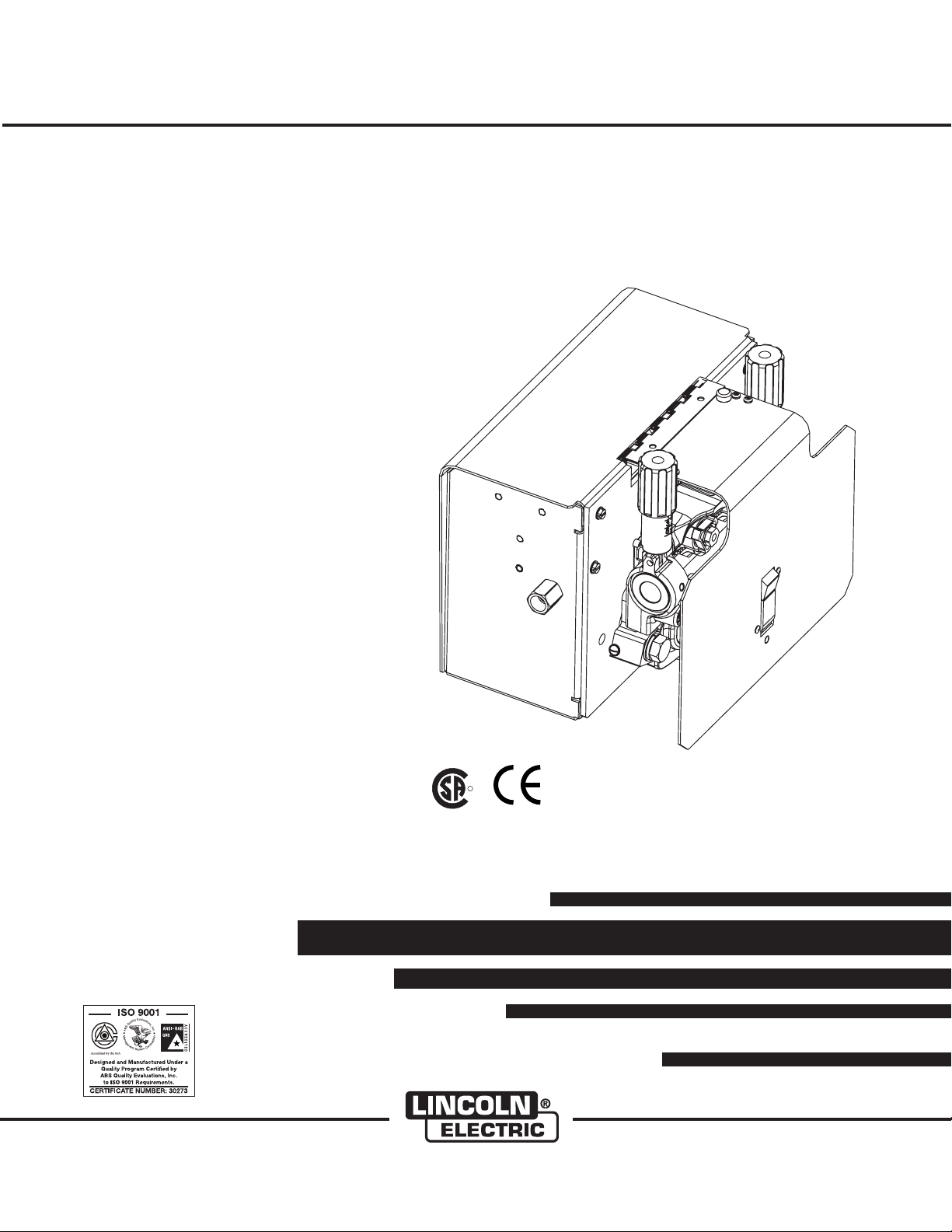
eCELL™ WIRE DRIVE SYSTEM
R
RETURN TO MAIN MENU
IM876-A
March, 2010
For use with machines having Code Numbers:
Safety Depends on You
Lincoln arc welding and cutting
equipment is designed and built
with safety in mind. However, your
overall safety can be increased by
proper installation ... and thoughtful op eration on yo ur part. DO
NOT INSTALL, OPERATE O R
REP A I R THIS EQU I P MENT
WIT H O UT REA D I NG THI S
MAN U A L AND T HE SA F E TY
PRE CAUT IONS CONT AINE D
THR O U GHOUT . And , mos t
importantly, think before you act
and be careful.
11240, 11721
Cleveland, Ohio 44117-1199 U.S.A. TEL: 216.481.8100 FAX: 216.486.1751 WEB SITE: www.lincolnelectric.com
IEC 60974-5
IP2x
OPERATOR’S MANUAL
Copyright © Lincoln Global Inc.
• World's Leader in Welding and Cutting Products •
• Sales and Service through Subsidiaries and Distributors Worldwide •
Page 2
i
SAFETY
WARNING
CALIFORNIA PROPOSITION 65 WARNINGS
Diesel engine exhaust and some of its constituents
are known to the State of California to cause cancer, birth defects, and other reproductive harm.
The Above For Diesel Engines
ARC WELDING CAN BE HAZARDOUS. PROTECT YOURSELF AND OTHERS FROM POSSIBLE SERIOUS INJURY OR DEATH.
KEEP CHILDREN AWAY. PACEMAKER WEARERS SHOULD CONSULT WITH THEIR DOCTOR BEFORE OPERATING.
Read and understand the following safety highlights. For additional safety information, it is strongly recommended that you
purchase a copy of “Safety in Welding & Cutting - ANSI Standard Z49.1” from the American Welding Society, P.O. Box
351040, Miami, Florida 33135 or CSA Standard W117.2-1974. A Free copy of “Arc Welding Safety” booklet E205 is available
from the Lincoln Electric Company, 22801 St. Clair Avenue, Cleveland, Ohio 44117-1199.
BE SURE THAT ALL INSTALLATION, OPERATION, MAINTENANCE AND REPAIR PROCEDURES ARE
PERFORMED ONLY BY QUALIFIED INDIVIDUALS.
The engine exhaust from this product contains
chemicals known to the State of California to cause
cancer, birth defects, or other reproductive harm.
The Above For Gasoline Engines
i
FOR ENGINE
powered equipment.
1.a. Turn the engine off before troubleshooting and maintenance
work unless the maintenance work requires it to be running.
____________________________________________________
1.b. Operate engines in open, well-ventilated
areas or vent the engine exhaust fumes
outdoors.
____________________________________________________
1.c. Do not a dd th e fuel near an open flame
welding arc or when the engine is running.
Stop the engine and allow it to cool before
refueling to prevent spilled fuel from vaporizing on conta ct with h ot engine parts and
igniting. Do not spill fuel when filling tank. If
fuel is spilled, wipe it up and do not start
engine until fumes have been eliminated.
____________________________________________________
1.d. Keep all equipment safety guards, covers and devices in
position and in good repair.Keep hands, hair, clothing and
tools away from V-belts, gears, fans and all other moving
parts when starting, operating or repairing equipment.
____________________________________________________
1.e. I n some cases it may be neces sa ry to r em ove sa fe ty
gu a rds to perf orm req u ire d mai nten a nce . Re m ove
guards only when necessary and replace them when the
ma i nten ance re q uiri ng t hei r r e mov a l i s c ompl ete.
Always use the greatest care when working near moving
parts.
___________________________________________________
1.f. Do not put your hands near the engine fan.
Do not attempt to override the governor or
idler by pushing on the throttle control rods
while the engine is running.
1.h. To avoid scalding, do not remove the
radiator pressure cap when the engine is
hot.
ELECTRIC AND
MAGNETIC FIELDS
may be dangerous
2.a. Electri c cur rent flowing throug h any cond uc tor causes
local ized Elect ric and Magnetic F ields (EMF ). Welding
curre nt creates EMF fie lds around welding cables an d
welding machines
2.b. E MF fields m ay interfere wi th some p ac em ak er s, and
welders having a pacemaker should consult their physician
before welding.
2.c. Exposure to EMF fields in welding may have other health
effects which are now not known.
2.d. All welders should use the following procedures in order to
minimize exposure to EMF fields from the welding circuit:
2.d.1.
Route the electrode and work cables together - Secure
them with tape when possible.
2.d.2. Nev er coil t he electrode lead ar ou nd your b od y.
2.d.3. Do not place your body between the electrode and
work cables. If the electrode cable is on your right
side, the work cable should also be on your right side.
___________________________________________________
1.g. To prevent accidentally starting gasoline engines while
turning the engine or welding generator during maintenance
work, disconnect the spark plug wires, distributor cap or
magneto wire as appropriate.
2.d.4. Connect the work cable to the workpiece as close as
possible to the area being welded.
2.d.5. Do not work next to welding power source.
Mar ‘95
Page 3
ii
SAFETY
ii
ELECTRIC SHOCK can
kill.
3.a. The electrode and work (or ground) circuits
are electrically “hot” when the welder is on.
Do not touch these “hot” parts with your bare
skin or wet clothing . Wea r dry , hol e-free
gloves to insulate hands.
3.b. Insulate yourself from work and ground using dry insulation.
Make certain the insulation is large enough to cover your full
area of physical contact with work and ground.
In addition to the normal safety precautions, if welding
mu st be pe rfor med un der el ectr ical ly haz ardous
conditions (in damp locations or while wearing wet
clothing; on metal structures such as floors, gratings or
scaffolds; when in cramped positions such as sitting,
kneeling or lying, if there is a high risk of unavoidable or
accidental contact with the workpiece or ground) use
the following equipment:
• Semiautomatic DC Constant Voltage (Wire) Welder.
• DC Manual (Stick) Welder.
• AC Welder with Reduced Voltage Control.
3.c. In semiautomatic or automatic wire welding, the electrode,
elect rode reel, weldin g h ead, nozzle or semia utomatic
welding gun are also electrically “hot”.
3.d. Always be sure the work cable makes a good electrical
connection with the metal being welded. The connection
should be as close as possible to the area being welded.
3.e. Ground the work or metal to be welded to a good electrical
(earth) ground.
3.f.
Maintain the electrode holder, work clamp, welding cable and
welding machine in good, safe operating condition. Replace
damaged insulation.
3.g. Never dip the electrode in water for cooling.
3.h. N ever s imultan eo usly t ouch e le ctrical ly “ho t” par ts of
electrode holders connected to two welders because voltage
between the two can be the total of the open circuit voltage
of both welders.
3.i. When working above floor level, use a safety belt to protect
yourself from a fall should you get a shock.
3.j. Also see Items 6.c. and 8.
ARC RAYS can burn.
4.a. Use a shield with the proper filter and cover
plates to protect your eyes from sparks and
the rays of the arc when welding or observing
open arc welding. Headshield and filter lens
should conform to ANSI Z87. I standards.
4.b. Use suitable clothing made from durable flame-resistant
material to protect your skin and that of your helpers from
the arc rays.
4.c. Protect other nearby personnel with suitable, non-flammable
screening and/or warn them not to watch the arc nor expose
themselves to the arc rays or to hot spatter or metal.
FUMES AND GASES
can be dangerous.
5.a. Welding may produce fumes and gases
hazardous to health. Avoid breathing these
fumes and ga ses. Wh en weld in g, ke ep
your head out of the fume. Use enough
ventilation and/or exhaust at the arc to keep
fumes and gases away from the breathing zone. When
we lding with electrode s whi ch req uire spec ial
ve ntil ation suc h as st ainless o r har d facing (s ee
instructions on container or MS DS) or on lead or
cadmium plated steel and other metals or coatings
which produce highly toxic fumes, keep exposure as
low as possible and within applicable OSHA PEL and
ACGIH TLV limits using local exhaust or mechanical
ventilation. In confined spaces or in some circumst ance s, ou tdoo rs, a r espi rator may be req uired.
Additional precautions are also required when welding
on galvanized steel.
5. b. The operation of welding fume control equipment is affected
by various factors including proper use and positioning of
the equipment, maintenance of the equipment and the specific welding procedure and application involved. Worker
exposure level should be checked upon installation and
periodically thereafter to be certain it is within applicable
OSHA PEL and ACGIH TLV limits.
5.c.
Do not weld in locations near chlorinated hydrocarbon
coming from degreasing, cleaning or spraying operations.
The heat and rays of the arc can react with solvent vapors
form phosgene, a highly toxic gas, and other irritating products.
5.d. Shielding gases used for arc welding can displace air and
cause i nj ur y or de at h. Always use enough ventilation,
especially in confined areas, to insure breathing air is safe.
vapors
to
5.e. Read and understand the manufacturer’s instructions for this
equipment and the consumables to be used, including the
ma t eria l s afet y d ata sh e et (MS D S) and fol low you r
employer’s safety practices. MSDS forms are available from
yo u r weld ing d i str i but o r or fr o m the m a nuf a ctur er.
5.f. Also see item 1.b.
Jan ‘09
Page 4
iii
SAFETY
iii
WELDING and CUTTING
SPARKS can
cause fire or explosion.
6.a.
Remove fire hazards from the welding area.
If this is not possible, cover them to prevent
Re m embe r th a t we l din g spa r ks an d ho t
materials from welding can easily go through small cracks
an d op eni ngs to a dja cen t ar eas. Avoi d weldi ng n ear
hydraulic lines. Have a fire extinguisher readily available.
6.b. Where compressed gases are to be used at the job site,
special precautions should be used to prevent hazardous
situations. Refer to “Safety in Welding and Cutting” (ANSI
Standar d Z49 .1) a nd th e ope rating infor mation for t he
equipment being used.
6.c. When not welding, make certain no part of the electrode
circuit is touching the work or ground. Accidental contact
can cause overheating and create a fire hazard.
6.d. Do not heat, cut or weld tanks, drums or containers until the
proper steps have been taken to insure that such procedures
will not cause flammable or toxic vapors from substances
inside. They can cause an explosion even
been “cleaned”. For information, purchase “Recommended
Safe Practices for the
Co n tain ers a n d Pi p ing T hat H a ve H e ld H a zar d ous
Substances”, AWS F4.1 from the American Welding Society
(see address above).
6.e. Vent hollow castings or containers before heating, cutting or
welding. They may explode.
Sparks and spatter are thrown from the welding arc. Wear oil
6.f.
free protective garments such as leather gloves, heavy shirt,
cuffless trousers, high shoes and a cap over your hair. Wear
ear plugs when welding out of position or in confined places.
Always wear safety glasses with side shields when in a
welding area.
6.g. Connect the work cable to the work as close to the welding
area as practical. Work cables connected to the building
framework or other locations away from the welding area
incre ase the possibi lity of the weldin g current passi ng
through lifting chains, crane cables or other alternate circuits. This can create fire hazards or overheat lifting chains
or cables until they fail.
6.h. Also see item 1.c.
the w el di ng sparks from s ta rt in g a fire.
though
they have
Preparation
for Welding and Cutting of
CYLINDER may explode
if damaged.
7.a. Us e o n ly com p ress ed gas cyl i nde r s
containing the correct shielding gas for the
pr o cess use d and pro p erl y ope rati ng
re g ulat ors d e sig n ed for th e g a s and
pressure used. All hoses, fittings, etc. should be suitable for
the application and maintained in good condition.
7.b. A lw ays keep cylinders in an u pr ig ht position s ecurely
chained to an undercarriage or fixed support.
7.c. Cylinders should be located:
• Away from areas where they may be struck or subjected to
physical damage.
• A safe distance from arc welding or cutting operations and
any other source of heat, sparks, or flame.
7.d. Never allow the electrode, electrode holder or any other
electrically “hot” parts to touch a cylinder.
7.e. Keep your head and face away from the cylinder valve outlet
when opening the cylinder valve.
7.f. Valve protection caps should always be in place and hand
tight except when the cylinder is in use or connected for
use.
7.g. R ead and follo w th e inst ructi ons on c om press ed g as
cylinders, associated equipment, and CGA publication P-l,
“Precautions for Safe Handling of Compressed Gases in
Cylinders,” available from the Compressed Gas Association
1235 Jefferson Davis Highway, Arlington, VA 22202.
FOR ELECTRICALLY
powered equipment.
8.a. Turn off input power using the disconnect
switch at the fuse box before working on
the equipment.
8.b. Install equi pment in accordance with the U.S. National
Electrical Code, a ll local codes and the manufacturer’ s
recommendations.
8.c. Ground the equipment in accordance with the U.S. National
Electrical Code and the manufacturer’s recommendations.
6.I. Read and follow NFPA 51B “ Standard for Fire Prevention
During Welding, Cutting and Other Hot Work”, available
from NFPA, 1 Batterymarch Park, PO box 9101, Quincy, Ma
022690-9101.
6.j. Do not use a welding power source for pipe thawing.
Refer to http://www.lincolnelectric.com/safety for additional safety information.
Jan ‘09
Page 5

iv
SAFETY
iv
PRÉCAUTIONS DE SÛRETÉ
Pour votre propre protection lire et observer toutes les instructions
et les précautions de sûreté specifiques qui parraissent dans ce
manuel aussi bien que les précautions de sûreté générales suivantes:
Sûreté Pour Soudage A L’Arc
1. Protegez-vous contre la secousse électrique:
a. Les circuits à l’électrode et à la piéce sont sous tension
quand la machine à souder est en marche. Eviter toujours
tout contact entre les parties sous tension et la peau nue
ou les vétements mouillés. Porter des gants secs et sans
trous pour isoler les mains.
b. Faire trés attention de bien s’isoler de la masse quand on
soude dans des endroits humides, ou sur un plancher
metallique ou des grilles metalliques, principalement dans
les positions assis ou couché pour lesquelles une grande
partie du corps peut être en contact avec la masse.
c. Maintenir le porte-électrode, la pince de masse, le câble
de soudage et la machine à souder en bon et sûr état
defonctionnement.
d.Ne jamais plonger le porte-électrode dans l’eau pour le
refroidir.
e. Ne jamais toucher simultanément les parties sous tension
des porte-électrodes connectés à deux machines à souder
parce que la tension entre les deux pinces peut être le
total de la tension à vide des deux machines.
f. Si on utilise la machine à souder comme une source de
courant pour soudage semi-automatique, ces precautions
pour le porte-électrode s’applicuent aussi au pistolet de
soudage.
2. Dans le cas de travail au dessus du niveau du sol, se protéger
contre les chutes dans le cas ou on recoit un choc. Ne jamais
enrouler le câble-électrode autour de n’importe quelle partie
du corps.
5. Toujours porter des lunettes de sécurité dans la zone de
soudage. Utiliser des lunettes avec écrans lateraux dans les
zones où l’on pique le laitier.
6. Eloigner les matériaux inflammables ou les recouvrir afin de
prévenir tout risque d’incendie dû aux étincelles.
7. Quand on ne soude pas, poser la pince à une endroit isolé de
la masse . Un court-ci rcuit acci dental peu t p rovoque r u n
échauffement et un risque d’incendie.
8. S’assurer que la masse est connectée le plus prés possible
de la zone de travail qu’il est pratique de le faire. Si on place
la masse sur la charpente de la construction ou d’autres
endroits éloignés de la zone de travail, on augmente le risque
de voir passer le courant de soudage par les chaines de levage, câbles de grue, ou autres circuits. Cela peut provoquer
des risques d’incendie ou d’echauffement des chaines et des
câbles jusqu’à ce qu’ils se rompent.
9. Assurer une ventilation suffisante dans la zone de soudage.
Ceci est particuliérement important pour le soudage de tôles
galvanisées plombées, ou cadmiées ou tout autre métal qui
produit des fumeés toxiques.
10. Ne pas souder en présence de vapeurs de chlore provenant
d’opérations de dégraissage, nettoyage ou pistolage. La
chaleur ou les rayons de l’arc peuvent réagir avec les vapeurs
du solvant pour produire du phosgéne (gas fortement toxique)
ou autres produits irritants.
11. Pour obtenir de plus amples renseignements sur la sûreté,
voir le code “Code for safety in welding and cutting” CSA
Standard W 117.2-1974.
PRÉCAUTIONS DE SÛRETÉ POUR
3. Un coup d’arc peut être plus sévère qu’un coup de soliel,
donc:
a. Utiliser un bon masque avec un verre filtrant approprié
ainsi qu’un verre blanc afin de se protéger les yeux du rayonnement de l’arc et des projections quand on soude ou
quand on regarde l’arc.
b. Porter des vêtements convenables afin de protéger la
peau de soudeur et des aides contre le rayonnement de
l‘arc.
c. Protéger l’autre p ersonnel travaillant à pr oximité a u
soudage à l’aide d’écrans appropriés et non-inflammables.
4. De s g outte s de laitie r e n fusion so nt émise s de l’arc de
soudage. Se protéger avec des vêtements de protection libres
de l’huile, tels que les gants en cuir, chemise épaisse, pantalons sans revers, et chaussures montantes.
LES MACHINES À SOUDER À
TRANSFORMATEUR ET À
REDRESSEUR
1. Relier à la terre le chassis du poste conformement au code de
l’électricité et aux recommendations du fabricant. Le dispositif
de montage ou la piece à souder doit être branché à une
bonne mise à la terre.
2. Autant que possible, I’installation et l’entretien du poste seront
effectués par un électricien qualifié.
3. Avant de faires des travaux à l’interieur de poste, la debrancher à l’interrupteur à la boite de fusibles.
4. Garder tous les couvercles et dispositifs de sûreté à leur
place.
Mar. ‘93
Page 6
TThhaannkk YYoouu
vv
for selecting a QUALITY product by Lincoln Electric. We want you
to take pride in operating this Lincoln Electric Company product
••• as much pride as we have in bringing this product to you!
The business of The Lincoln Electric Company is manufacturing and selling high quality welding equipment, consumables, and cutting equipment. Our challenge is to meet the needs of our customers and to exceed their expectations. On occasion, purchasers may ask Lincoln
Electric for advice or information about their use of our products. We respond to our customers based on the best information in our possession at that time. Lincoln Electric is not in a position to warrant or guarantee such advice, and assumes no liability, with respect to such information or advice. We expressly disclaim any warranty of any kind, including any warranty of fitness for any customer’s particular purpose,
with respect to such information or advice. As a matter of practical consideration, we also cannot assume any responsibility for updating or
correcting any such information or advice once it has been given, nor does the provision of information or advice create, expand or alter any
warranty with respect to the sale of our products.
Lincoln Electric is a responsive manufacturer, but the selection and use of specific products sold by Lincoln Electric is solely within the control
of, and remains the sole responsibility of the customer. Many variables beyond the control of Lincoln Electric affect the results obtained in
applying these types of fabrication methods and service requirements.
Subject to Change – This information is accurate to the best of our knowledge at the time of printing. Please refer to www.lincolnelectric.com
for any updated information.
CUSTOMER ASSISTANCE POLICY
Please Examine Carton and Equipment For Damage Immediately
When this equipment is shipped, title passes to the purchaser upon receipt by the carrier. Consequently, Claims
for material damaged in shipment must be made by the purchaser against the transportation company at the
time the shipment is received.
Please record your equipment identification information below for future reference. This information can be
found on your machine nameplate.
Product _________________________________________________________________________________
Model Number ___________________________________________________________________________
Code Number or Date Code_________________________________________________________________
Serial Number____________________________________________________________________________
Date Purchased___________________________________________________________________________
Where Purchased_________________________________________________________________________
Whenever you request replacement parts or information on this equipment, always supply the information you
have recorded above. The code number is especially important when identifying the correct replacement parts.
On-Line Product Registration
- Register your machine with Lincoln Electric either via fax or over the Internet.
• For faxing: Complete the form on the back of the warranty statement included in the literature packet
accompanying this machine and fax the form per the instructions printed on it.
• For On-Line Registration: Go to our
“Product Registration”. Please complete the form and submit your registration.
Read this Operators Manual completely before attempting to use this equipment. Save this manual and keep it
handy for quick reference. Pay particular attention to the safety instructions we have provided for your protection.
The level of seriousness to be applied to each is explained below:
WEB SITE at www.lincolnelectric.com. Choose “Quick Links” and then
WARNING
This statement appears where the information must be followed exactly to avoid serious personal injury or loss of life.
CAUTION
This statement appears where the information must be followed to avoid minor personal injury or damage to this equipment.
Page 7

vi
TABLE OF CONTENTS
Page
––––––––––––––––––––––––––––––––––––––––––––––––––––––––––––––––––––––––––––––––
Installation.......................................................................................................................Section A
Technical Specifications.......................................................................................................A-1
Wire Drive Features and Components .................................................................................A-2
Safety Precautions ...............................................................................................................A-3
Mounting and Unit Dimensions ............................................................................................A-3
Safety Precautions ...............................................................................................................A-4
Weld Cable Sizes ........................................................................................................................A-4
Coaxial Weld Cables ............................................................................................................A-5
External Shut Down Signal...................................................................................................A-6
Digitial Control Cable Connection ........................................................................................A-6
Setting Electrode Polarity .....................................................................................................A-7
Wire Drive Configuration ......................................................................................................A-8
Assembly of Drive Rolls and Wire Guides............................................................................A-9
Pressure Arm Adjustment ..................................................................................................A-10
Shielding Gas Connection..................................................................................................A-10
Wire Reel Loading..............................................................................................................A-11
________________________________________________________________________________
Operation.........................................................................................................................Section B
Safety Precautions ...............................................................................................................B-1
Graphic Symbols, Common Welding Abbreviations.............................................................B-1
Product Description, Recommended Processes and Required Equipment .........................B-2
Front And Rear Controls and Connections ..........................................................................B-3
1. Status LED ................................................................................................................B-4
2. Cold Feed / Gas Purge Switch..................................................................................B-4
3. 5-pin Amphenol .........................................................................................................B-4
________________________________________________________________________________
vi
Accessories.....................................................................................................Section C
General Options / Accessories...............................................................C-1 Thru C-3
________________________________________________________________________
Maintenance ....................................................................................................Section D
Safety Precautions ................................................................................................D-1
Routine Maintenance.............................................................................................D-1
Periodic Maintenance............................................................................................D-1
Calibration Specification........................................................................................D-1
________________________________________________________________________
Troubleshooting............................................................................................................E
Safety Precautions.................................................................................................E-1
How To Use Troubleshooting Guide......................................................................E-1
Troubleshooting .............................................................................................E-2, E-3
Wiring Diagram ......................................................................................................F-1
________________________________________________________________________
Parts Lists................................................................................................................P522
________________________________________________________________________
Page 8
A-1
TECHNICAL SPECIFICATIONS
CODE. TYPE WIRE FEED SPEED RANGE
Gearing
INSTALLATION
:
eCELL™Wire Drive System
GMAW FCAW
A-1
11240
CODE TYPE
11240
WELDING CAPACITY RATING
Amp Rating Duty Cycle
600 A 60%
500 A 100%
Dimensions do not include wire reel.
Normal Speed
CONTROL BOX, WIRE DRIVE AND COMPLETE UNITS
INPUT POWER
Input Voltage Dimensions
and Current Height Width Depth Weight Operating Storage
eCELL™ 40 VDC ( 241mm) ( 231mm) ( 287mm) (8.6 Kg.) -10°C to 40°C -40°C to 85°C
4 Amps
WFS Range
50 – 800 ipm
(1.3-20.3 m/min.)
9.5“ 9.1“ 11.3“ 19 Lbs 14°F to 104°F -40°F to 185°F
Wire Sizes
.023 – .045
(0.6 – 1.2mm)
PHYSICAL SIZE• TEMPERATURE RATING
WFS Range
50 – 800 ipm
(1.3-20.3 m/min.)
Wire Sizes
.030 - .045
(0.8 - 1.2mm)
ITEMS INCLUDED WITH EACH PRODUCT
CODE
11240
OPERATING TEMPERATURE RANGE
Description
eCELL™
Wire Drive
System
15°F to 104°F(-10°C to 40°C)
Wire Feeder
eCELL™
Wire Drive
Wire Reel Stand
------------
Drive Roll Kit
----------
TEMPERATURE RANGES
STORAGE TEMPERATURE RANGE
-40°F to 185°F(-40°C to 85°C)
eCELL™ WIRE DRIVE SYSTEM
Gun Bushing
K1500-1
Control Cable
---------
Page 9
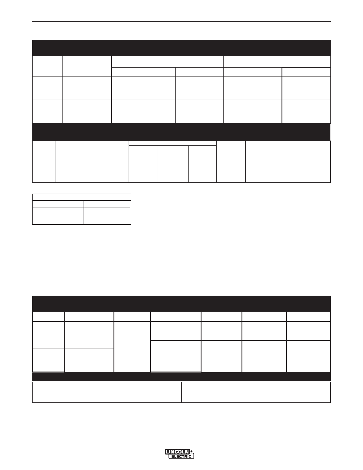
A-2
4 DRIVE ROLLS
S
PLIT WIRE GUIDE
ADJUSTABLE
PRESSURE ARMS
G
AS OUTLET
GUN RECEIVER BUSHING
FOR GUN AND CABLE
ASSEMBLY
GAS PURGEGAS PURGE
COLD FEEDCOLD FEED
G
AS INGAS IN
L12529-2 VM
TIGHTENTIGHTEN
LOOSENLOOSEN
U U11
4
0 VDC40 VDC
I I
11
4A 4A
X
X
60% 60%
100%100%
II
2
2
600A 600A
500A500A
ÆÆ
STATUSSTATUS
ELECTRIC
LINCOLN
ARCLINK STATUS LED
ARCLINK CONNECTION
(5 PIN AMPHENOL)
COLD FEED
GAS PURGE
TOGGLE SWITCH
GAS INLET
INSTALLATION
eCELL™ WIRE DRIVE FEATURES AND COMPONENTS
DOOR REMOVED
A-2
SEE INSTALLATION AND OPERATION SECTIONS FOR DETAILED INFORMATION
REAR VIEW
eCELL™ WIRE DRIVE SYSTEM
Page 10
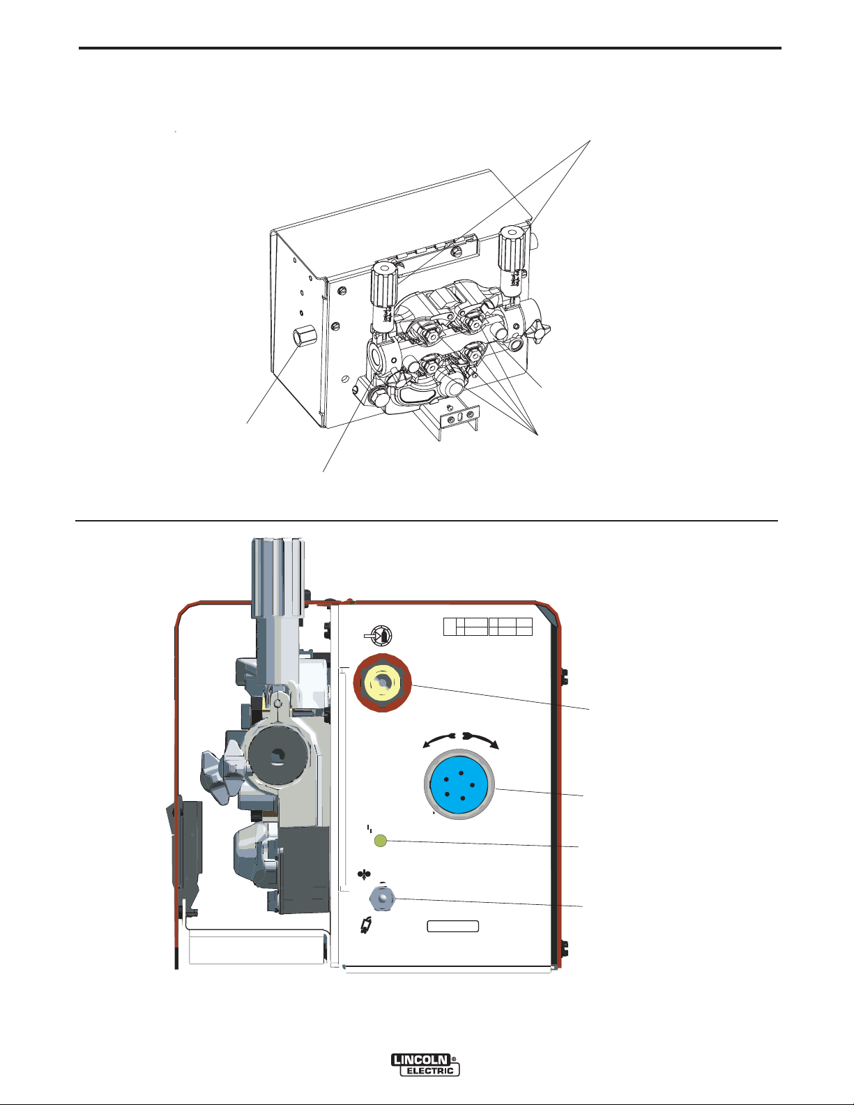
A-3
2.762.76
1.381.38
2.382.38
6.006.00
2.252.25
5/16 - 18 THREADS5/16 - 18 THREADS
(4 PLACES)(4 PLACES)
4.974.97
8.508.50
9.939.93
11.2511.25
4.974.97
1.391.39
8.828.82
5.085.08
8.508.50
INSTALLATION
SAFETY PRECAUTION
WARNING
ELECTRIC SHOCK can kill.
• Turn the input power OFF at the
welding power source before installation or changing drive rolls and/or
guides.
• Do not touch electrically live parts.
• When inching with the gun trigger, electrode
and drive mechanism are "hot" to work and
ground and could remain energized several
seconds after the gun trigger is released.
• Welding power source must be connected to
system ground per the National Electrical Code
or any applicable local codes.
• Only qualified personnel should perform maintenance work.
----------------------------------------------------------------------------------------
FIGURE A.1
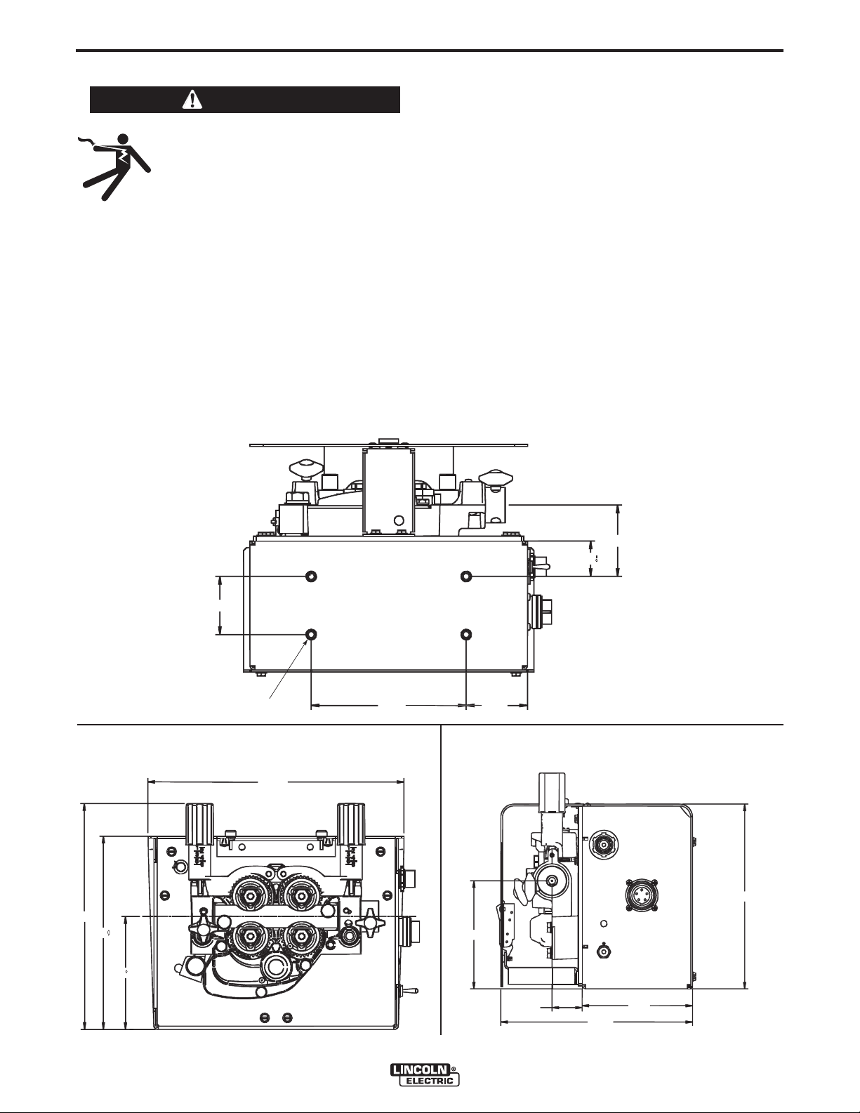
A-3
MOUNTING AND UNIT DIMENSIONS
Mount the eCell™ Wire Drive System on the designated bracket of the eCell™ only.
Side View (Door not shown for clarity). (See Figure A.2)
Rear View. (See Figure A.3)
(See Figure A.1).
FIGURE A.2
FIGURE A.3
eCELL™ WIRE DRIVE SYSTEM
Page 11

A-4
INSTALLATION
SAFETY PRECAUTION
ELECTRIC SHOCK can kill.
• Only qualified personnel should
perform this installation.
• Turn off the input power to the
power source at the disconnect switch or fuse
box before working on this equipment. Turn off
the input power to any other equipment connected to the welding system at the disconnect
switch or fuse box before working on this equipment.
• Do not touch electrically hot parts.
----------------------------------------------------------------------
WELD CABLE SIZES
Table A.1 has the copper cable sizes recommended
for different currents and duty cycles. Lengths stipulated are the distance from the welder to work and
back to the welder again. Cable sizes are increased
for greater lengths primarily for the purpose of minimizing voltage loss in the welding circuit.
TABLE A.1
RECOMMENDED CABLE SIZES (RUBBER COVERED COPPER - RATED 75°C [167°F] )**
A-4
CABLE SIZES FOR COMBINED LENGTHS OF ELECTRODE AND WORK CABLES
Percent
Duty
Amperes
200
200
225
225
250
250
250
250
300
325
350
400
400
500
** Tabled values are for operation at ambient temperatures of 40°C (104°F) and below. Applications above 40°C
(104°F) may require cables larger than recommended, or cables rated higher than 75°C (167°F).
Cycle
60
100
20
40 & 30
30
40
60
100
60
100
60
60
100
60
0 to 50 Ft.
0 to 15 m
2
2
4 or 5
3
3
2
1
1
1
2/0
1/0
2/0
3/0
2/0
50 to 100Ft.
15 to 31 m
2
2
3
3
3
2
1
1
1
2/0
1/0
2/0
3/0
2/0
100 to 150 Ft.
31 to 48 m
2
2
2
2
2
1
1
1
1
2/0
2/0
2/0
3/0
3/0
150 to 200 Ft.
48 to 61 m
1
1
1
1
1
1
1
1
1/0
2/0
2/0
3/0
3/0
3/0
200 to 250 Ft.
61 to 76 m
1/0
1/0
1/0
1/0
1/0
1/0
1/0
1/0
2/0
3/0
3/0
4/0
4/0
4/0
eCELL™ WIRE DRIVE SYSTEM
Page 12

A-5
Electrode
Work
Work
Power Source
Work
Electrode
Wire Feeder
Electrode
Work
Coaxial Weld Cable
INSTALLATION
A-5
COAXIAL WELD CABLES
Coaxial welding cables are specially designed welding
cables for pulse welding. Coaxial weld cables feature
low inductance, allowing fast changes in the weld current. Regular cables have a higher inductance which
may distor t the puls e wave shap e . In d u c tance
becomes more severe as the weld cables become
longer.
Coaxial weld cables are recommended for all pulse
welding, especially when the total weld cable length
(e lectrode cable + work ca ble) exceeds 50 fe et
(7.6m).
A coaxial weld cable is constructed by 8 small leads
wrapped around one large lead. The large inner lead
connects to the electrode stud on the power source
and the electrode connection on the wire feeder. The
small leads combine together to form the work lead,
one end attached to the power source and the other
end to the work piece.
(See Coaxial weld Cable below.)
WORK CONNECTION
Connect a work lead of sufficient size between the
proper output stud on the power source and the work.
Be sure the connection to the work makes tight metal
to metal electrical contact. Poor work lead connections can result in poor welding performance.
eCELL™ WIRE DRIVE SYSTEM
Page 13

A-6
EXTERNAL
DEVICE
570
570A/570B
E
D
C
B
A
E
D
C
B
A
P
OWER SOURCE
W
IRE FEEDER
INSTALLATION
A-6
EXTERNAL SHUTDOWN SIGNAL
WARNING
ELECTRIC SHOCK can kill.
• Turn the input power OFF at the disconnect switch before working on
this equipment.
• Do not touch electrically hot parts.
• Only qualified personnel should install, use or
service this equipment.
------------------------------------------------------------------------
The eCell™ Wire Drive includes one input for an
external shut-off circuit. The circuit interrupts the trigger signal and stops the welding process in the event
of a fault. The most common use is for a flow switch
when using water cooled guns or torches.
The external device must have "normally closed" contacts.
Do not use the external shut-off circuits for safety or
emergency stops.
To connect to the shutoff circuit:
1. Turn off power to the wire feeder at the disconnect
switch.
2. Remove the screws securing the wrap-around and
door assembly.
3. Locate leads 570 and 570A/570B in the harness
for external shut-off switch. (See Figure A.4)
DIGITAL CONTROL CABLE, K1543-XX
ArcLink/LincNet control cables are special high quality
cables for digital communication. The cables are copper 5 conductor cable in a SO-type rubber jacket.
There is one 20 gauge twisted pair for network communications. This pair has an impedance of approximately 120 ohms and a propagation delay per foot of
less than 2.1 nanoseconds. There are two 12 gauge
conductors that are used to supply 40VDC to the network. The fifth wire is 18 gauge and is used as an
electrode sense lead.
Use of non-standard cables may lead to system shutdowns, poor arc starting and wire feeding problems.
The control cables connect the power source to the
wire feeder, and the wire feeder to other wire feeders.
PIN FUNCTION
A Digital I/O
B Digital I/O
C "67" voltage sense
D 40 VDC
E Common
4. Wire the external equipment to the leads. Route
the wiring for the external equipment through the
rear of the wire feeder.
5. Reassemble the wrap-around and door assembly.
6. Restore power.
FIGURE A.4
eCELL™ WIRE DRIVE SYSTEM
Use a maximum of 250 feet (76.2m) of control cable
between components.
Page 14

A-7
1 2 3 4 5 6 7 8
O
N
- (Negative) Polarity
LOCATION DIP SWITCH
1 2 3 4 5 6 7 8
O
N
+ (Positive) Polarity
eCELL WIRE DRIVE BOARD
INSTALLATION
A-7
SETTING ELECTRODE POLARITY
WARNING
ELECTRIC SHOCK can kill.
• Turn the input power OFF at the disconnect switch before working on
this equipment.
• Do not touch electrically hot parts.
• Only qualified personnel should install, use or
service this equipment.
CAUTION
When changing the electrode polarity, the weld
cables must be changed at the power source
studs and the DIP switches inside the eCell™ Wire
Drive System must be properly set. Operation
with the DIP switch in the wrong position will
cause erratic arc performance.
------------------------------------------------------------------------
The eCell™ Wire Drive is factory set for Electrode
Positive welding.
To change the DIP switch inside the eCell™ Wire
Drive for electrode polarity: (See Figure A.5)
1. Turn off power at the welding power source.
2. Remove the sheet metal wrap-around on the wire
drive.
3. Locate DIP switches on the Wire Drive Board.
4. Set DIP switch #7 to the desired polarity.
DIP Switch #7 Position Polarity
ON - (negative) polarity
OFF + (positive) polarity
5. Assemble the wrap-around to the wire drive.
6. Restore power.
Most GMAW we lding proce dure s use Elec trod e
Positive welding. Some Innershield procedures may
use Electrode Negative welding.
FIGURE A.5
eCELL™ WIRE DRIVE SYSTEM
Page 15

A-8
GUN RECEIVER BUSHING
CONNECTOR
BLOCK
SOCKET
HEAD CAP
SCREW
THUMB
SCREW
LOOSEN
CAP
SCREW
TIGHTEN
CAP
SCREW
INSTALLATION
WIRE DRIVE CONFIGURATION
(See Figure A.6)
Changing the Gun Receiver Bushing
WARNING
ELECTRIC SHOCK can kill.
• Turn the input power OFF at the
welding power source before installation or changing drive rolls and/or
guides.
• Do not touch electrically live parts.
• When inching with the gun trigger, electrode and
drive mechanism are "hot" to work and ground
and could remain energized several seconds
after the gun trigger is released.
• Only qualified personnel should perform maintenance work.
------------------------------------------------------------------------
Tools required:
• 1/4" hex key wrench
Note: Some gun bushings do not require the use of
the thumb screw.
A-8
6. Remove the outer wire guide, and push the gun
bushing out of the wire drive. Because of the precision fit, light tapping may be required to remove
the gun bushing.
7. Disconnect the shielding gas hose from the gun
bushing, if required.
8. Connect the shielding gas hose to the new gun
bushing, if required.
9. Rotate the gun bushing until the thumb screw hole
aligns with the thumb screw hole in the feed plate.
Slide the gun receiver bushing into the wire drive
and verify the thumb screw holes are aligned.
10. Tighten the socket head cap screw.
11. Insert the welding gun into the gun bushing and
tighten the thumb screw.
1. Turn power off at the welding power source.
2. Remove the welding wire from the wire drive.
3. Remove the thumb screw from the wire drive.
4. Remove the welding gun from the wire drive.
5. Loosen the socket head cap screw that holds the
connec t o r b ar against t h e g u n bushing.
Important: Do not attempt to completely
remove the socket head cap screw.
FIGURE A.6
eCELL™ WIRE DRIVE SYSTEM
Page 16

OUTER WIRE GUIDE
4 TRIANGULAR RINGS
IN UNLOCKED POSITION
2 PRESSURE ARMS
ROTATE DOWN
INNER WIRE GUIDE
DRIVE ROLLS
DRIVE HUBS
PRESSURE ARMS
IN OPEN POSITION
SLIDE DRIVE ROLL
ON DRIVE HUB
TRIANGULAR RING IN
UNLOCKED POSITION
TRIANGULAR RING IN
LOCKED POSITION
A-9
INSTALLATION
ASSEMBLY OF DRIVE ROLLS AND WIRE
GUIDES
WARNING
A-9
To install drive rolls and wire guides:
(See Figure A.7 and A.7a)
1. Turn off power at the welding power source.
ELECTRIC SHOCK can kill.
• Turn the input power OFF at the
welding power source before installation or changing drive rolls and/or
guides.
• Do not touch electrically live parts.
• When inching with the gun trigger, electrode
and drive mechanism are "hot" to work and
ground and could remain energized several seconds after the gun trigger is released.
• Only qualified personnel should perform maintenance work.
-----------------------------------------------------------------------To remove drive rolls and wire guides:
(See Figure A.7)
1. Turn power off at the welding power source.
2. Remove the outer wire guide.
3. Rotate 4 triangular rings to the unlocked position.
4. Open the pressure arms.
2. Open pressure arms.
3. Assemble the inner wire guide.
4. Slide the drive rolls onto the drive hubs.
(See figure A.8)
5. Close the pressure arms.
6. Rotate 4 triangular rings to the locked position.
(See figure A.8a)
7. Assemble the outer wire guide.
8. Adjust the pressure arms to the recommended setting.
FIGURE A.8
5. Remove the drive rolls and inner wire guide.
FIGURE A.7
FIGURE A.8a
eCELL™ WIRE DRIVE SYSTEM
Page 17

A-10
ALUM INUM
OUTERSHIELD
META LS HIE LD
INNERSHIELD
STEEL
STAINLE SS
CORED WIRES
SOLID WIR ES
6
1
3
2
5
4
INSTALLATION
A-10
PRESSURE ARM ADJUSTMENT
WARNING
ELECTRIC SHOCK can kill.
• Turn the input power OFF at the welding power
source before installation or changing drive
rolls and/or guides.
• Do not touch electrically live parts.
• When inching with the gun trigger, electrode
and drive mechanism are "hot" to work and
ground and could remain energized several seconds after the gun trigger is released.
• Only qualified personnel should perform maintenance work.
------------------------------------------------------------------------
The pressure arm controls the amount of force the
drive rolls exert on the wire. Proper adjustment of
both pressure arms gives the best welding performance.
Set the pressure arm as follows (See Figure A.9):
Aluminum wires between 1 and 3
Cored wires between 3 and 4
Steel, Stainless wires between 4 and 6
For best results, use the same setting on both pressure arms. This maximizes traction of the drive rolls
while minimizing wire deformation.
FIGURE A.9
BUILD-UP OF SHIELDING GAS may
harm health or kill.
• Shut off shielding gas supply when
not in use.
SEE AMERICAN NATIONAL STANDARD Z-49.1,
"SAFETY IN WELDING AND CUTTING" PUBLISHED BY THE AMERICAN WELDING SOCIETY.
------------------------------------------------------------------------
Maximum inlet pressure is 100 psi. (6.9 bar.)
Install the shielding gas supply as follows:
1. Secure the cylinder to prevent it from falling.
2. Remove the cylinder cap. Inspect the cylinder
valves and regulator for damaged threads, dirt,
dust, oil or grease. Remove dust and dirt with a
clean cloth. DO NOT ATTACH THE REGULATOR
IF OIL, GREASE OR DAMAGE IS PRESENT!
Inform your gas supplier of this condition. Oil or
grease in the presence of high pressure oxygen is
explosive.
3. Stand to one side away from the outlet and open
the cylinder valve for an instant. This blows away
any dust or dirt which may have accumulated in the
valve outlet.
4. Attach the flow regulator to the cylinder valve and
tighten the union nut(s) securely with a wrench.
Note: if connecting to 100% CO
regulator adapter between regulator and cylinder
valve. If adapter is equipped with a plastic washer,
be sure it is seated for connection to the CO
der.
cylinder, insert
2
cylin-
2
SHIELDING GAS CONNECTION
WARNING
CYLINDER may explode if damaged.
• Keep cylinder upright and chained to
support.
• Keep cylinder away from areas where
it may be damaged.
• Never lift welder with cylinder attached.
• Never allow welding electrode to touch cylinder.
• Keep cylinder away from welding or other live electrical circuits.
---------------------------------------------------------------------------
eCELL™ WIRE DRIVE SYSTEM
5. Attach one end of the inlet hose to the outlet fitting
of the flow regulator. Attach the other end to the
welding system shielding gas inlet. Tighten the
union nuts with a wrench.
6. Before opening the cylinder valve, turn the regulator
adjusting knob counterclockwise until the adjusting
spring pressure is released.
7. Standing to one side, open the cylinder valve slowly
a fraction of a turn. When the cylinder pressure
gage stops moving, open the valve fully.
8. The flow regulator is adjustable. Adjust it to the flow
rate recommended for the procedure and process
being used before making a weld.
Page 18

A-11
INSTALLATION
WIRE REEL LOADING
WARNING
• Keep hands, hair, clothing and tools away from
rotating equipment.
• Do not wear gloves when threading wire or
changing wire spool.
• Only qualified personnel should install, use or
service this equipment.
-----------------------------------------------------------------------
The eCell™ Wire Drive is designed for use with bulk
packages of wire – reels, drums and boxes.
Connect the consumable package to the wire drive
using K515-xx wire conduit. For best results, locate
the wire near the wire drive and keep the conduit as
straight as possible.
A-11
eCELL™ WIRE DRIVE SYSTEM
Page 19

B-1
OPERATION
SAFETY PRECAUTIONS
Read this entire section of operating instructions
before operating the machine.
WARNING
B-1
GRAPHIC SYMBOLS THAT APPEAR ON
THIS MACHINE OR IN THIS MANUAL
COLD FEED
ELECTRIC SHOCK can kill.
• Unles s using cold f e ed fe a t u re,
when feeding with the gun trigger,
the electrode and drive mechanism
are always electricall y ene rgized
and could remain energized several
seconds after welding ceases.
• Do not touch electrically live parts or electrodes
with your skin or wet clothing.
• Insulate yourself from the work and ground.
• Always wear dry insulating gloves.
-------------------------------------------------------------
ONLY QUALIFIED PERSONS SHOULD INSTALL,
USE OR SERVICE THIS EQUIPMENT. READ AND
FOL LOW T HE M ANUFAC TURER ’ S INSTRUC TIONS, EMPLOYER’S SAFETY PRACTICES AND
MATERIAL SAFETY DATA SHEETS (MSDS) FOR
CONSUMABLES.
-----------------------------------------------------------
READ THIS WARNING, PROTECT YOURSELF &
OTHERS.
FUMES AND GASES can be dangerous.
• Keep your head out of fumes.
POSITIVE OUTPUT
NEGATIVE OUTPUT
PROTECTIVE
GROUND
WARNING OR
CAUTION
DANGEROUS
VOLTAGE
SHOCK
HAZARD
WELDING
FUMES
EXPLOSION
• Use ventilation or exhaust at the
arc, o r both, t o keep f u m e s and
gases from your breathing zone and
general area.
WELDING SPARKS can cause fire or
explosion.
• Do not weld near flammable material.
• Do not weld on containers which have
held flammable material.
ARC RAYS can burn.
• Wear eye, ear, and body protection.
-----------------------------------------------------------
Ob ser ve ad dit ion al gu ide lin es de tai led in the
beginning of this manual.
GAS INPUT
WORK
CONNECTION
PURGE BY GAS
COMMON WELDING ABBREVIATIONS
WFS
• Wire Feed Speed
CV
• Constant Voltage
GMAW (MIG)
• Gas Metal Arc Welding
FCAW (Innershield or Outershield)
• Flux Core Arc Welding
eCELL™ WIRE DRIVE SYSTEM
Page 20

B-2
OPERATION
PRODUCT DESCRIPTION
General Physical Description
The eCell™ Wire Drive System is the wire feeder for
the eCell™. It consists of a 4 roll wire drive with connections for the torch, electrode conduit and shielding
gas. The small, lightweight feeder mounts at the rear
of the eCell™.
General Functional Description
The eCell™ Wire Drive System is a robotic wire drive
that operates only with the eCell™. All welding parameters (WFS, voltage, etc.) are set through the robotic controller. Integrated in the wire drive is a robotic
wire drive module. The eCell™ Wire Drive module
communicates with the robotic control and Power
Wave power source via ArcLink.
The wire drive is capable of wire feed speeds of 50 –
800 ipm. Accurate speed control is obtained with a
tachometer integrated in the motor. The wire drive is
capable of feeding both forward and reverse.
The heart of the eCell™ Wire Drive is the MaxTrac™
4 roll wire drive.
This new 4 roll drive MaxTrac™ technology delivers
great feeding because:
• Patent pending drive rolls improve traction.
• The precision machined, rigid aluminum
alloy frame results in maximum drive roll
clamping pressure.
• Drive hubs with steel inner cores have 3 ball
bearings inside each hub.
• The drive hubs are supported by large, heat
treated and ground shafts for maximum
rigidity and accurate drive roll alignment.
• Patent pending dual spring pressure arms
have sensitivity for feeding soft wires without
crushing them, and have plenty of compression force for feeding solid or stiff wires.
B-2
RECOMMENDED PROCESSES
GMAW AND GMAW-STT
•
• FCAW
PROCESS LIMITATIONS
• The eCell™ Wire Drive is not recommended for
GTAW, CAG, SMAW, SAW
• The eCell™ Wire Drive is not compatible with pushpull equipment.
REQUIRED EQUIPMENT
All power sources must be part of the eCell™ system.
These include:
• PowerWave 355M
• PowerWave 455M
• PowerWave 455M/STT
• PowerWave 455M Robotic
• PowerWave 455M/STT Robotic
EQUIPMENT LIMITATIONS
• Maximum GMAW gun length =25’ (7.6m)
• Maximum conduit length = 25' (7.6m)
• Maximum total control cable length = 100ft (31m)
• The eCell™ Wire Drive works only with ArcLink
equipment.
• Other gun bushings are required for welding guns
that do not have a "Lincoln" back-end.
Easy to confi g u r e , ea s y to se r v i ce pa rts give
MaxTrac™ drives the edge in productivity.
• Patented split wire guides fully support the
wire and virtually eliminate birdnesting.
• No tools required to change the drive rolls
and wire guides.
• Changeable gun bushings easily accept
guns from many manufacturers.
• Brass-to-brass connections between the
electrode connection and the gun minimize
voltage drop variations, resulting in consistent arc performance all day, every day.
Functions that can be operated without the robot controller are gas purge and cold feed.
eCELL™ WIRE DRIVE SYSTEM
Page 21

B-3
eCELL
eCELL
WIRE DRIVE SYSTEMWIRE DRIVE SYSTEM
ÆÆ
TM
TM
GAS OUT
GAS OUT
L12529-1 VML12529-1 VM
GAS PURGEGAS PURGE
COLD FEEDCOLD FEED
GAS INGAS IN
L12529-2 VM
TIGHTENTIGHTEN
LOOSENLOOSEN
U U11
4
0 VDC40 VDC
I I
11
9A 9A
X X
60% 60%
100%100%
II
22
600A 600A
500A500A
ÆÆ
STATUSSTATUS
ELECTRIC
LINCOLN
OPERATION
FRONT AND REAR PANEL CONTROLS CONNECTIONS
CASE FRONT CONTROLS
B-3
FIGURE B.1
GAS OUTLET
FIGURE B.2
1
GAS INLET
2
ITEM DESCRIPTION
1 Status LED
2
3 5-pin amphenol for ArcLink connecting Digital Control Cable. See Installation Section for
Cold Feed - Gas Purge Switch, press the switch up to feed wire with weld output off. Press the
switch down for gas flow with weld output off.
detail.
3
eCELL™ WIRE DRIVE SYSTEM
Page 22

B-4
OPERATION
B-4
1. ARCLINK STATUS LED
The status LED indicates system status. Normal
operation is a steady green light.
Note: During normal power-up, the LED may flash
red and/or green as the equipment performs self tests.
LED condition Definition
Steady green System okay. The power source and wire feed-
Blinking green Occurs during a reset and indicates the power
Alternating green Non-recov erable system fault. If the power
and red
er are communicating normally.
source is identifying each component in the
system. This is normal for the first 10 seconds
after power-up, or if the system configuration is
changed during operation.
source or wire feeder status LED is flashing
any combination of red and green, errors are
present in the system. Read the error code
before the machine is turned off.
Instructions for r ea di ng the error c od e are
detailed in the Service Manual. Individual code
digit s are flas hed i n red with a long pause
between digits. If more than one code is present, the codes will be separated by a green
light.
3. 5-PIN AMPHENOL FOR ARCLINK
DIGITAL CONTROL CABLE
(See Installation Section for details)
To clear the error, turn the power source OFF,
and then back ON to reset. See troubleshooting
section.
Steady red Non recoverable hardware fault. Generally indi-
Blinking red Not applicable.
cates a problem with the cables connecting the
wire feeder to the power source.
2. COLD FEED/GAS PURGE SWITCH
Cold Feed and Gas Purge are combined into a single
spring centered toggle switch.
To activate Cold Feeding, hold the switch
in the UP position. The wire drive will feed
electrode but neither the power source nor
the gas solenoid will be energized. Adjust
the speed of cold feeding by rotating the
WFS knob. Cold feeding, or "cold inching"
the electrode is useful for threading the
electrode through the gun.
Hold with toggle switch in the DOWN position to activate Gas Purge and let the shielding gas flow. The
gas solenoid valve will energize but neither the power
source output nor the drive motor will be turned on.
The Gas Purge switch is useful for setting the proper
flow rate of shielding gas. Flow meters should always
be adjusted while the shielding gas is flowing.
eCELL™ WIRE DRIVE SYSTEM
Page 23

C-1
DRIVE ROLLS
INNER WIRE
GUIDE
ACCESSORIES
OPTIONAL KITS AND ACCESSORIES
DRIVE ROLL KITS
Drive Roll Kits, Steel Wires
Includes: 4 Smooth V groove drive rolls and inner
wire guide.
KP1505-030S .023-.030 (0.6-0.8mm)
KP1505-035S .035 (0.9mm)
KP1505-040S .040 (1.0mm)
KP1505-045S .045 (1.2mm)
Drive Roll Kits, Cored Wires
Includes: 4 Knurled drive rolls and inner wire guide.
C-1
KP1505-035C .030-.035" (0.8-0.9mm)
KP1505-045C .040-.045" (1.0-1.2mm)
Drive Roll Kits, Aluminum Wire
Includes: 4 polished U groove drive rolls, outer wire
guide and inner wire guide.
KP1507-035A .035" (0.9 mm)
KP1507-040A .040" (1.0mm)
KP1507-3/64A 3/64" (1.2mm)
eCELL™ WIRE DRIVE SYSTEM
Page 24

C-2
K1543-xx
Control Cable.
ACCESSORIES
OPTIONAL KITS:
Includes: 5 pin to 5 pin wire
feeder to power source control
cable.
C-2
K1500-1
K1500-2
K1500-3
K1500-4
K1500-5
K466-2
Gun Receiver Bushing (for guns
with K466-1 Lincoln gun connec-
tors; Innershield and Subarc guns.)
Gun Receiver Bushing (for guns with
K466-2, K466-10 Lincoln gun connec-
tors; Magnum 200/300/400 guns and
compatible with Tweco® #4.)
Gun Receiver Bushing (for guns
with K613-7 Lincoln gun connec-
tors; Magnum 550 guns and com-
patible with Tweco® #5.)
Gun Receiver Bushing (for gun
with K466-3 Lincoln gun connec-
tors; compatible with Miller® guns.)
Gun Receiver Bushing (compatible
with Oxo® guns.)
Magnum 200/300/400 to K1500-2
Adapter.
Includes: Gun receiver bush-
ing, set screw and hex key
wrench.
Includes: Gun receiver bush-
ing with hose nipple, set screw
and hex key wrench.
Includes: Gun receiver bush-
ing with hose nipple, set screw
and hex key wrench.
Includes: Gun receiver bush-
ing with hose nipple, set screw
and hex key wrench.
Includes: Gun receiver bush-
ing with hose nipple, 4 guide
tubes, set screw and hex key
wrench.
Includes: Gun adapter, cotter
pin, hex key wrench, wrench.
K613-7
K1546-1
K1546-2
K659-1
3000290
K586-1
Magnum 550 to K1500-3 Adapter
Lincoln Conduit.
Incoming Bushing, for Lincoln
Conduit .025- 1/16" (0.6 - 1.6mm)
wire.
Incoming Bushing, for Lincoln
Conduit 1/16-1/8" (1.6 - 3.2 mm )
wire.
Gas Guard Regulator
Adjustable Gas Regulator
Deluxe Adjustable Gas Regulator
eCELL™ WIRE DRIVE SYSTEM
Includes: Trigger adapter, gun
adapter and hex key wrench.
Includes: Incoming bushing
and hex key wrench.
Includes: Incoming bushing
and hex key wrench.
Includes: Gas Guard
Regulator and adjustment key.
Includes: Gas Regulator for
Mixed Gases and 10' (3.0m)
Hose.
Includes: Deluxe Gas
Regulator for Mixed Gases,
Adapter for CO2 and 10'
(3.0m) Hose.
Page 25

C-3
ACCESSORIES
OPTIONAL KITS:
K1733-1 Wire Straightener.
ED0020219 Fiber Hat for Speed-Feed Drums.
K836-1 Dereeler Adapter.
K884-5 Accu-Trak Drum Payoff Kit – 20 inch
diameter.
K884-6 Accu-Trak Drum Payoff Kit – 23 inch
diameter.
K895-2 Rotary Wire Dispenser.
K2175-1 500 lb. Accu-Pak Box Payoff Kit.
K2175-2 1000 lb. Accu-Pak Box Payoff Kit.
K515-xx Wire Conduit.
C-3
eCELL™ WIRE DRIVE SYSTEM
Page 26

D-1
MAINTENANCE
D-1
MAINTENANCE
Safety Precautions
WARNING
ELECTRIC SHOCK can kill.
• Do not touch electrically live parts
such as output terminals or internal wiring.
• When inching with gun trigger, electrode and
drive mechanism are “hot” to work and ground
and could remain energized several seconds
after the gun trigger is released.
• Turn OFF input power at welding power source
before installation or changing drive roll and/or
guide tubes.
• Welding power source must be connected to
system ground per the National Electrical Code
or any applicable local codes.
• Only qualified personnel should perform maintenance work.
------------------------------------------------------------------------
Observe all additional Safety Guidelines detailed
throughout this manual.
To verify the wire feed speed,
• Assemble a .045 (1.2 mm) drive roll kit to the feeder.
• Remove the gun from the wire drive.
• Load .045 (1.2 mm) steel wire into the feeder. Trim
the wire flush with the front surface of the gun bushing.
• Adjust the wire feed speed to 300 in/min with the
robotic controller.
• Activate and hold the COLD FEED switch for 10
seconds.
• Cut the wire flush with the front surface of the gun
bushing. The wire length should be 50 in/min ± 2.5
in/min.
ROUTINE MAINTENANCE
• Clean and tighten all weld terminals.
• Inspect all weld cables, control cables, gun cables
and shielding gas hoses. Repair or replace as necessary.
PERIODIC MAINTENANCE
• Clean drive roll grooves.
• Blow out or vacuum the inside of the feeder.
CALIBRATION SPECIFICATION
WARNING
ELECTRIC SHOCK can kill.
• Do not touch electrically live parts.
• When inching with the gun trigger, electrode, wire drive motor
and drive mechanism are "hot" to
work and ground and coul d
remain energized several seconds
after the gun trigger is released.
• Welding power source must be
connected to system ground per
the National Electrical Code or
any applicable local codes.
• Only qualified personnel should perform maintenance work.
------------------------------------------------------------------------
eCELL™ WIRE DRIVE SYSTEM
Page 27

E-1
TROUBLESHOOTING
E-1
WARNING
• Turn the input power OFF at the welding power source before installation or changing
drive rolls and/or guides.
• Do not touch electrically live parts.
• When inching with the gun trigger, electrode and drive mechanism are "hot" to work and
ground and could remain energized several seconds after the gun trigger is released.
• Welding power source must be connected to system ground per the National Electrical
Code or any applicable local codes.
• Only qualified personnel should perform maintenance work.
Observe all additional Safety Guidelines detailed throughout this manual.
ELECTRIC SHOCK can kill.
HOW TO USE TROUBLESHOOTING GUIDE
Service and Repair should only be performed by Lincoln Electric Factory Trained Personnel.
Unauthorized repairs performed on this equipment may result in danger to the technician and
machine operator and will invalidate your factory warranty. For your safety and to avoid Electrical
Shock, please observe all safety notes and precautions detailed throughout this manual.
__________________________________________________________________________
This Troubleshooting Guide is provided to help you
locate and repair possible machine malfunctions.
Simply follow the three-step procedure listed below.
Step 1. LOCATE PROBLEM (SYMPTOM).
Look under the column labeled “PROBLEM (SYMPTOMS)”. This column describes possible symptoms
that the machine may exhibit. Find the listing that
best describes the symptom that the machine is
exhibiting.
Step 2. POSSIBLE CAUSE.
The second column labeled “POSSIBLE CAUSE” lists
the obvious external possibilities that may contribute
to the machine symptom.
Step 3. RECOMMENDED COURSE OF ACTION
This co lumn prov ide s a cour se of action for the
Possible Cause, generally it states to contact your
local Lincoln Authorized Field Service Facility.
If you do not understand or are unable to perform the
Recommended Course of Action safely, contact your
local Lincoln Authorized Field Service Facility.
CAUTION
If for any reason you do not understand the test procedures or are unable to perform the tests/repairs safely, contact your
Local Lincoln Authorized Field Service Facility for technical troubleshooting assistance before you proceed.
eCELL™ WIRE DRIVE SYSTEM
Page 28

E-2
Observe all Safety Guidelines detailed throughout this manual
PROBLEMS
(SYMPTOMS)
OUTPUT PROBLEMS
The wire feeder does not feed wire
and the drive rolls do not spin.
TROUBLESHOOTING
POSSIBLE
CAUSE
1. Verify the power source is turned
on.
2. Verify the circuit breaker for the
wire feeder on the power source
has not tripped.
3. Verify power is being supplied to
the wire feeder.
E-2
RECOMMENDED
COURSE OF ACTION
The wire feeds erraticall y, or the
Motor Thermal LED lights.
No shielding gas
1. Verify the correct drive rolls and
inner wire guide are installed in
the wire drive.
2. Check for sharp bends in the gun
liner.
3. Examine the contact tip for wear
and proper size. Replace as necessary.
4. Check the gun liner. The welding
electr o d e shou l d slide easily
through the gun.
5. Ver i fy t h e proper gun liner is
installed.
6. Adjust the pressure arm.
7. Verif y the wire slides ea s i l y
through the conduit.
1. Verify the gas supply is turned on
and not empty.
2. Che c k the g a s hose f or c u ts.
Make sure it is not crushed.
3. Verify the shielding gas hose is
connected to the gun bushing or
welding gun.
If all recommended possible areas of
misadjustment have been checked
and the problem persists, Contact
your local Lincoln Authorized
Field Service Facility.
Variable or "hunting" arc.
A motor overload error occurs
1. Check for proper size contact.
Make sure the contact tip is not
worn, free of spatter and not melted.
2. Clean and tighten all electrode
and work connections.
3. Verify the proper polarity is being
used for the weld procedure.
4. Make sure the proper electrode
stick-out is being maintained.
5. Check the gas flow rate and mixture.
6. Verify the gun bushing is tightly
mounted in the wire drive.
7. Verify the gun is tightly mounted
to the gun bushing.
CAUTION
If for any reason you do not understand the test procedures or are unable to perform the tests/repairs safely, contact your
Local Lincoln Authorized Field Service Facility for technical troubleshooting assistance before you proceed.
eCELL™ WIRE DRIVE SYSTEM
Page 29

E-3
PROBLEMS
(SYMPTOMS)
TROUBLESHOOTING
Observe all Safety Guidelines detailed throughout this manual
POSSIBLE
CAUSE
RECOMMENDED
COURSE OF ACTION
E-3
A motor overload error occurs.
When the welding arc is activated, the
drive rolls spin but no arc is present.
1. Check for sharp bends i n the gu n
liner.
2. Examine the contact tip for wear and
proper size. Replace as necessary.
3. Check the gun liner. The welding
electrode should slide easily through
the gun.
4. Verify the proper gun liner is installed.
5. Reduce the pressure arm setting.
6. Verify the wire slides easily through
the conduit.
1. Check all electrode and work connections.
2. Verify th e gu n bushing is ti g h t l y
secured in the wire drive.
3. Verify the gun is tightly mounted to the
gun bushing.
If all recommended possible areas of
misadjustment have been checked
and the problem persists, Contact
your local Lincoln Authorized
Field Service Facility.
CAUTION
If for any reason you do not understand the test procedures or are unable to perform the tests/repairs safely, contact your
Local Lincoln Authorized Field Service Facility for technical troubleshooting assistance before you proceed.
eCELL™ WIRE DRIVE SYSTEM
Page 30

F-1
WIRING DIAGRAM
F-1
eCELL™ WIRE DRIVE SYSTEM
NOTE: This diagram is for reference only. It may not be accurate for all machines covered by this manual. The specific diagram for a particular code is pasted inside
the machine on one of the enclosure panels. If the diagram is illegible, write to the Service Department for a replacement. Give the equipment code number.
Page 31

WARNING
Spanish
AVISO DE
PRECAUCION
● Do not touch electrically live parts or
electrode with skin or wet clothing.
● Insulate yourself from work and
ground.
● No toque las partes o los electrodos
bajo carga con la piel o ropa mojada.
● Aislese del trabajo y de la tierra.
● Keep flammable materials away.
● Mantenga el material combustible
fuera del área de trabajo.
● Wear eye, ear and body protection.
● Protéjase los ojos, los oídos y el
cuerpo.
French
ATTENTION
German
WARNUNG
Portuguese
ATENÇÃO
Japanese
Chinese
Korean
Arabic
● Ne laissez ni la peau ni des vête-
ments mouillés entrer en contact
avec des pièces sous tension.
● Isolez-vous du travail et de la terre.
● Berühren Sie keine stromführenden
Teile oder Elektroden mit Ihrem
Körper oder feuchter Kleidung!
● Isolieren Sie sich von den
Elektroden und dem Erdboden!
● Não toque partes elétricas e elec-
trodos com a pele ou roupa molhada.
● Isole-se da peça e terra.
● Gardez à l’écart de tout matériel
inflammable.
● Entfernen Sie brennbarres Material!
● Mantenha inflamáveis bem guarda-
dos.
● Protégez vos yeux, vos oreilles et
votre corps.
● Tragen Sie Augen-, Ohren- und Kör-
perschutz!
● Use proteção para a vista, ouvido e
corpo.
READ AND UNDERSTAND THE MANUFACTURER’S INSTRUCTION FOR THIS EQUIPMENT AND THE CONSUMABLES TO BE
USED AND FOLLOW YOUR EMPLOYER’S SAFETY PRACTICES.
SE RECOMIENDA LEER Y ENTENDER LAS INSTRUCCIONES DEL FABRICANTE PARA EL USO DE ESTE EQUIPO Y LOS
CONSUMIBLES QUE VA A UTILIZAR, SIGA LAS MEDIDAS DE SEGURIDAD DE SU SUPERVISOR.
LISEZ ET COMPRENEZ LES INSTRUCTIONS DU FABRICANT EN CE QUI REGARDE CET EQUIPMENT ET LES PRODUITS A
ETRE EMPLOYES ET SUIVEZ LES PROCEDURES DE SECURITE DE VOTRE EMPLOYEUR.
LESEN SIE UND BEFOLGEN SIE DIE BETRIEBSANLEITUNG DER ANLAGE UND DEN ELEKTRODENEINSATZ DES HERSTELLERS. DIE UNFALLVERHÜTUNGSVORSCHRIFTEN DES ARBEITGEBERS SIND EBENFALLS ZU BEACHTEN.
Page 32

● Keep your head out of fumes.
● Use ventilation or exhaust to
remove fumes from breathing zone.
● Turn power off before servicing.
● Do not operate with panel open or
guards off.
WARNING
● Los humos fuera de la zona de res-
piración.
● Mantenga la cabeza fuera de los
humos. Utilice ventilación o
aspiración para gases.
● Gardez la tête à l’écart des fumées.
● Utilisez un ventilateur ou un aspira-
teur pour ôter les fumées des zones
de travail.
● Vermeiden Sie das Einatmen von
Schweibrauch!
● Sorgen Sie für gute Be- und
Entlüftung des Arbeitsplatzes!
● Mantenha seu rosto da fumaça.
● Use ventilação e exhaustão para
remover fumo da zona respiratória.
● Desconectar el cable de ali-
mentación de poder de la máquina
antes de iniciar cualquier servicio.
● Débranchez le courant avant l’entre-
tien.
● Strom vor Wartungsarbeiten
abschalten! (Netzstrom völlig öffnen; Maschine anhalten!)
● Não opere com as tampas removidas.
● Desligue a corrente antes de fazer
serviço.
● Não toque as partes elétricas nuas.
● No operar con panel abierto o
guardas quitadas.
● N’opérez pas avec les panneaux
ouverts ou avec les dispositifs de
protection enlevés.
● Anlage nie ohne Schutzgehäuse
oder Innenschutzverkleidung in
Betrieb setzen!
● Mantenha-se afastado das partes
moventes.
● Não opere com os paineis abertos
ou guardas removidas.
Spanish
AVISO DE
PRECAUCION
French
ATTENTION
German
WARNUNG
Portuguese
ATENÇÃO
Japanese
Chinese
Korean
Arabic
LEIA E COMPREENDA AS INSTRUÇÕES DO FABRICANTE PARA ESTE EQUIPAMENTO E AS PARTES DE USO, E SIGA AS
PRÁTICAS DE SEGURANÇA DO EMPREGADOR.
Page 33

• World's Leader in Welding and Cutting Products •
• Sales and Service through Subsidiaries and Distributors Worldwide •
Cleveland, Ohio 44117-1199 U.S.A. TEL: 216.481.8100 FAX: 216.486.1751 WEB SITE: www.lincolnelectric.com
 Loading...