

Page 1
Date of Purchase:______________
Serial Number:_________________
Code Number:_________________
Model:________________________
Where Purchased:______________
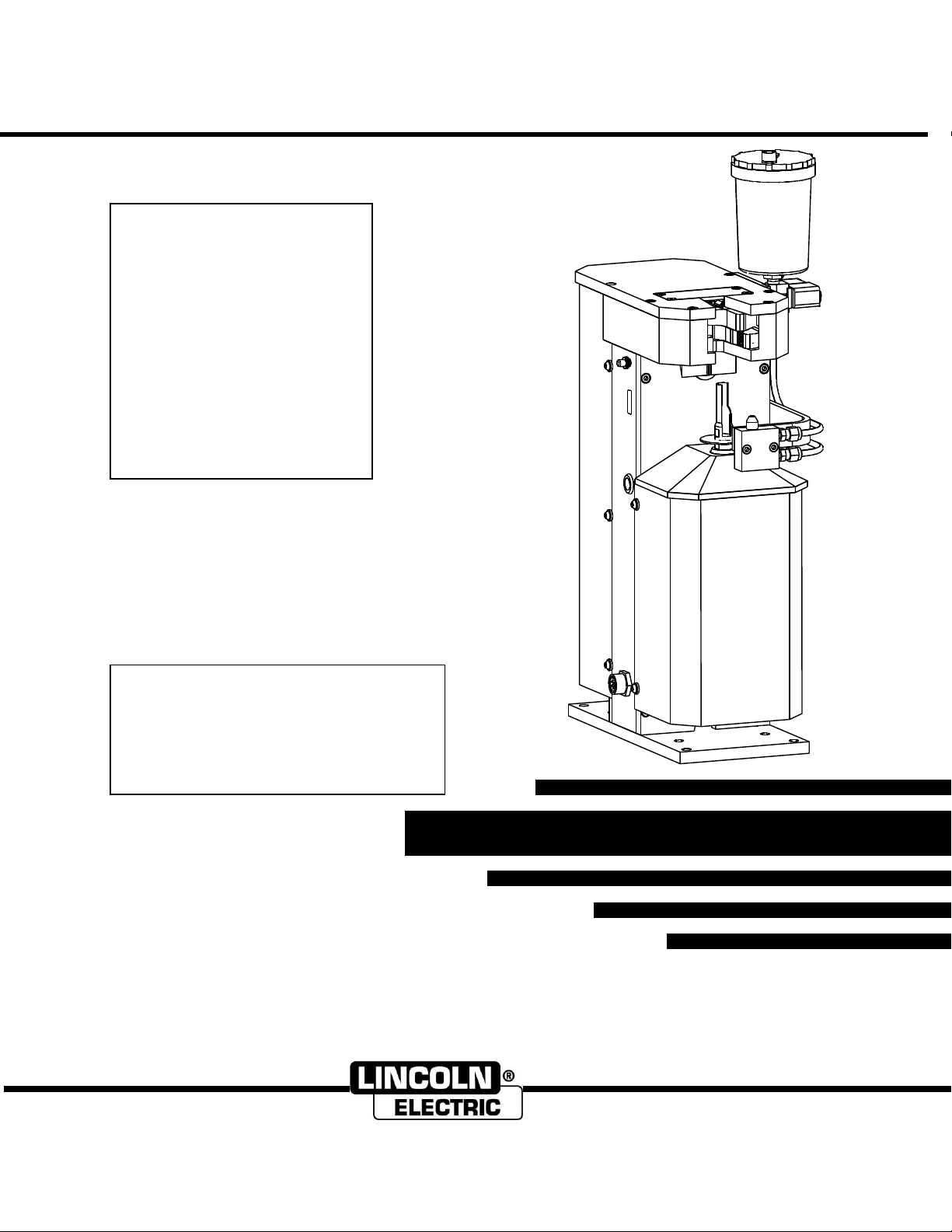
POWER REAM August, 2010
Safety Depends on You
Lincoln arc welding and cutting
equipment is designed and built
with safety in mind. However, your
overall safety can be increased by
proper installation ... and thoughtful
operation on your part.
DO NOT INSTALL, OPERATE OR
REPAIR THIS EQUIPMENT
WITHOUT READING THIS
MANUAL AND THE SAFETY
PRECAUTIONS CONTAINED
THROUGHOUT. And, most
importantly, think before you act
and be careful.
• Sales and Service through Subsidiaries and Distributors Worldwide •
Cleveland, Ohio 44117-1199 U.S.A. TEL: 216.481.8100 FAX: 216.486.1751 WEB SITE: www.lincolnelectric.com
• World's Leader in Welding and Cutting Products •
OPERATOR’S MANUAL
RETURN TO MAIN MENU
For use with machines having code number 11172
IM866
Page 2

IM866
POWER REAM
Page 3

Safety Information - 3 -
Before installation and commissioning of the POWER REAM, please read and understand all of the
following safety information. Failure to follow these instructions may result in damage to the equipment or
personal injury.
The POWER REAM is constructed to be safe to operate provided
- Only authorized personnel shall perform installation, commissioning and maintenance and all safety
precautions in these operating instructions shall be observed.
-The accident prevention regulations as well as the safety specifications referenced below are
observed
ANSI/RIA R15.06-1999 Industrial Robots and Robot Systems —Safety Requirements
-For additional safety information see references below
This product shall be integrated into a robot cell with independent safety system by plant engineering.
Install within a secured area, which is only to be entered by qualified personnel for maintenance work or
robot programming.
Before assembling, adjusting or working with the reamer, ensure all equipment in the area is locked out
and disabled.
The torch-cleaning unit is to be used only for torch cleaning within the parameters of its technical
specification.
Do not exceed the specified operating pressure of 80 PSI.
The torch-cleaning unit may only be operated with the cover closed when operated independently.
Keep hands away from unit while in operation.
Keep hands away from the clamp and reamer operating space.
Keep hands away from the wire cutter
Keep eyes away from the sprayer
Shut off the air supply when making adjustment so that the equipment is not pressurized.
Additional fittings or accessories that are not offered from the manufacturer may only be installed with the
approval from the manufacturer.
Do not use the reamer with corrosive or aggressive vapors or liquids without first obtaining approval from
the manufacturer.
Ensure that there is nothing in the reamer unit when shutting down the system.
Warning and instruction labels from the unit are not to be removed or defaced.
For additional safety information, refer to the following publications:
ANSI STANDARD Z49.1, SAFETY IN WELDING AND CUTTING,
American Welding Society, 550 LeJeune Rd. P.O. Box 351040, Miami, FL 33126
ANSI/RIA STANDARD R15.06-1999 Industrial Robots and Robot Systems —Safety
Requirements
American National Standards Institute, 1430 Broadway, New York, NY 10018
Canadian Standards Association; Z434-03 Industrial Robots and Robot Systems – General Safety
Requirements.
5060 Spectrum Way, Mississauga, Ontario, L4W 5N6, CANADA
POWER REAM
Page 4
Safety Information - 4 -
Moving parts can crush and cut.
Keep hands away from the
operating area of the reamer,
clamp, and wire cutter
Rotating Cutter.
Keep hands away from the operating area of the cutter.
Entanglement Hazard.
Do not operate with exposed long hair, jewelry or loose clothing.
Turn off power before servicing.
Turn off air supply and disconnect air supply hose before servicing.
Do not use damaged, frayed or deteriorated air hoses and fittings.
Maintain safe operating pressure (80 psi).
Safety Symbols used in this manual
POWER REAM
Page 5

Table of Contents - 5 -
Page
Safety Information……………………………………………………….. 3
Specifications………………………………………………………………… 6
Installation…………………………………………………………………….. 7
I/O Configuration………………………………………………………….. 10
Robot Programming………………………………………………………. 12
Operation………………………………………………………………………. 15
Feature Setups………………………………………………………………. 16
Automatic I/O Configuration…………………………………………. 18
Maintenance and Troubleshooting………………………………… 19
Diagnostics…………………………………………………………………….. 20
Parts Replacement………………………………………………………… 21
Pneumatic Diagram………………………………………………………. 29
Electrical Diagram…………………………………………………………. 30
Parts Diagram………………………………………………………………… 32
Optional Accessories……………………………………………………… 35
POWER REAM
Page 6

SPECIFICATIONS - 6 -
Pressure: 80 psi
Voltage: 24V DC
Speed: 1100 rpm
Flow: 15 scfm
Current: 0.5A DC
Power: 0.65 Hp
PNEUMATIC SPECIFICATIONS
ELECTRICAL SPECIFICATIONS
REAMING SPECIFICATIONS
PHYSICAL DIMENSIONS
HEIGHT
19.50 in. (495mm)
without Reservoir /
24.90 in. (633mm)
with Reservoir
WIDTH
8.47 in
228 mm
DEPTH
13.25 in
337 mm
NET WEIGHT
62 lbs.
28 kgs.
Nozzle inside diameter compatibility: 1/2‖, 5/8‖, 3/4‖
See section ―optional accessories‖ for product numbers
REAMING BIT SPECIFICATIONS
Minimum wire diameter: 0.030‖ (0.8mm)
Maximum wire diameter: 0.063‖ (1.6mm)
WIRE CUTTING SPECIFICATIONS
Use recommended water based anti spatter fluid in this product.
See section ―optional accessories‖ for product numbers.
Do not use oil based anti spatter fluid.
ANTI SPATTER FLUID SPECIFICATIONS
POWER REAM – (K2391-1)
Caution: Use Filtered (5 µm), Non Lubricated, Regulated Air
POWER REAM
Page 7
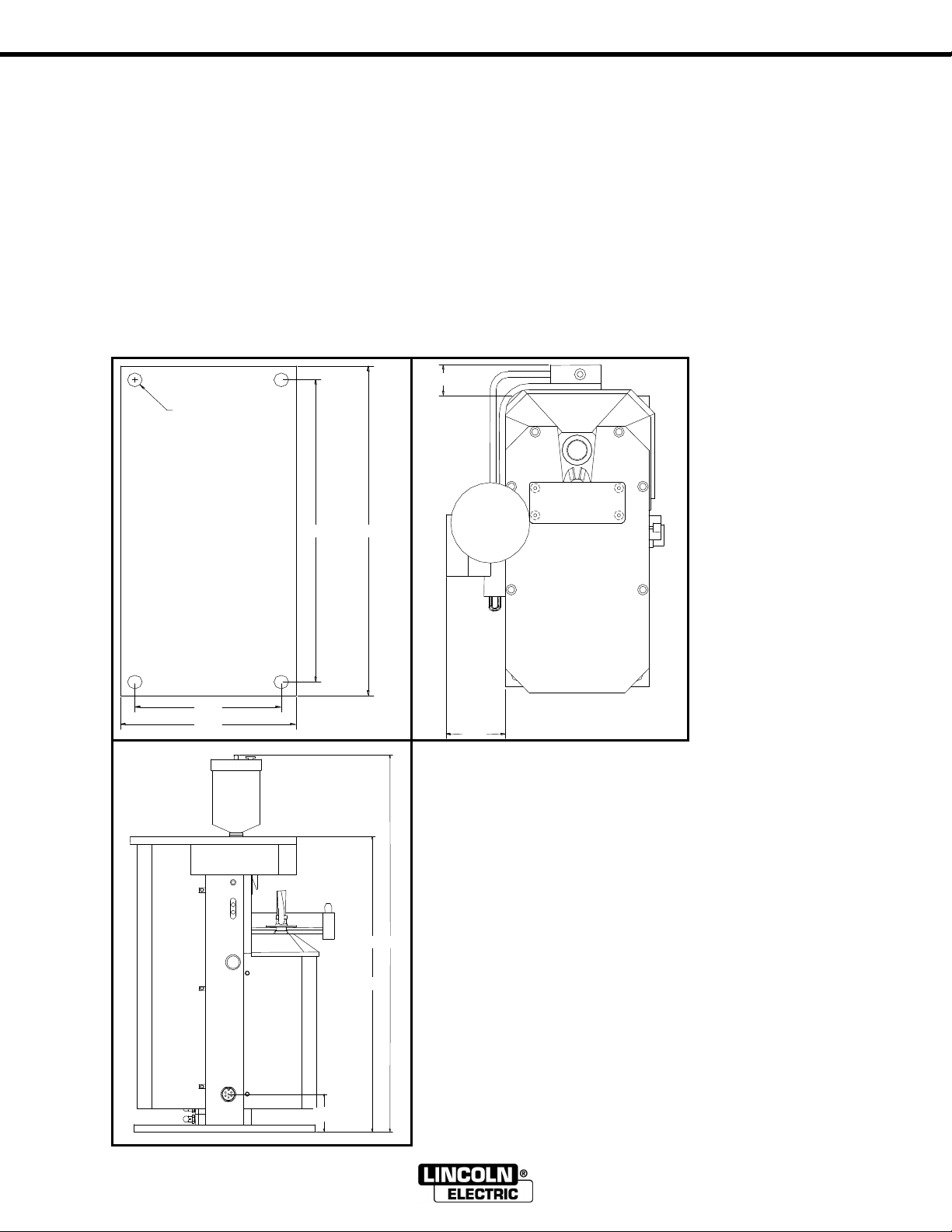
INSTALLATION - 7 -
12.00
11.00
5.00
6.00
Mounting Hole (4x)
1.25
2.47
2.50
24.90
19.50
Installation:
Before starting installation work in the area of the robot, ensure for your personal safety that all
protective measures have been taken and will remain in place while you are in the area of the
robot.
Danger of accident when connecting the pneumatic or electrical supply!
-Ensure that the air supply and electrical power to the torch maintenance center are
disconnected until the installation is complete.
-The torch maintenance center should be installed within the weld cell at a convenient location.
Be sure to consider movable fixtures, the confines of the robot and maintenance personnel
accessibility.
-Before operating the unit, ensure that the correct reaming bit for the torch is applied.
-Affix torch maintenance center base to sturdy platform using the four boltholes provided for 3/8‖
mounting hardware.
POWER REAM
Page 8
INSTALLATION - 8 -
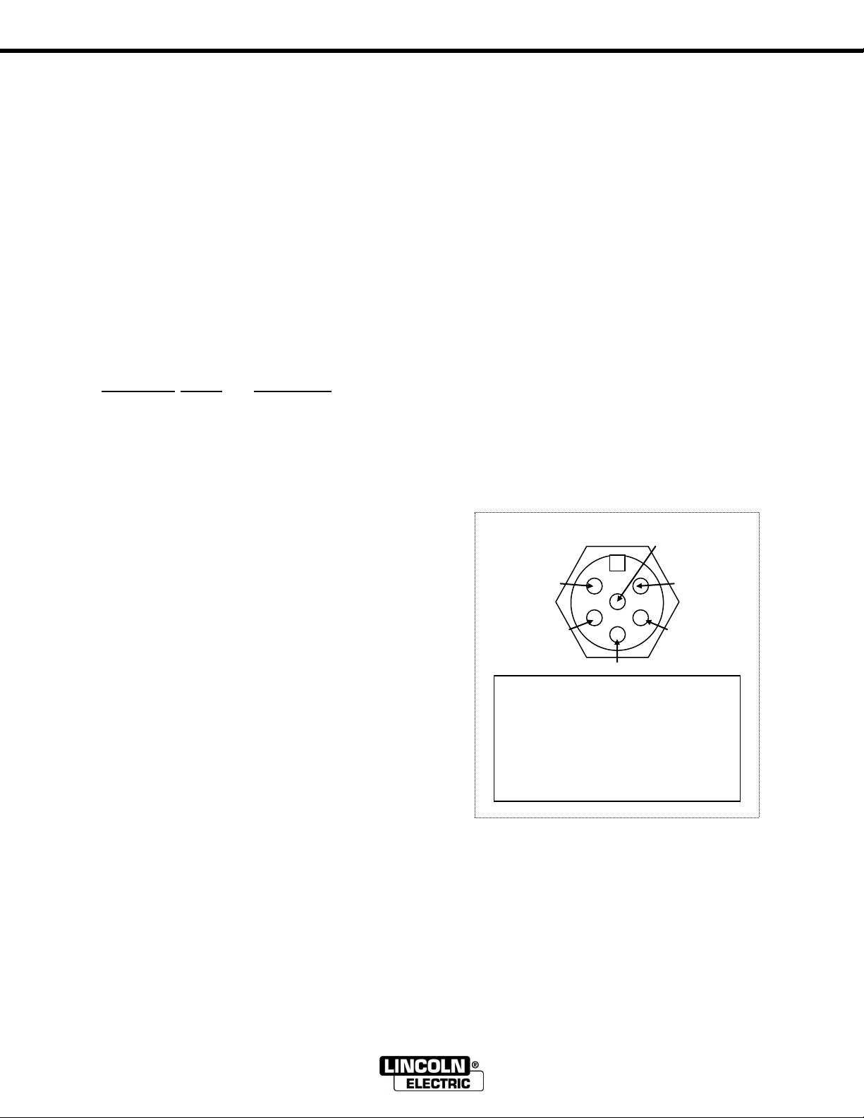
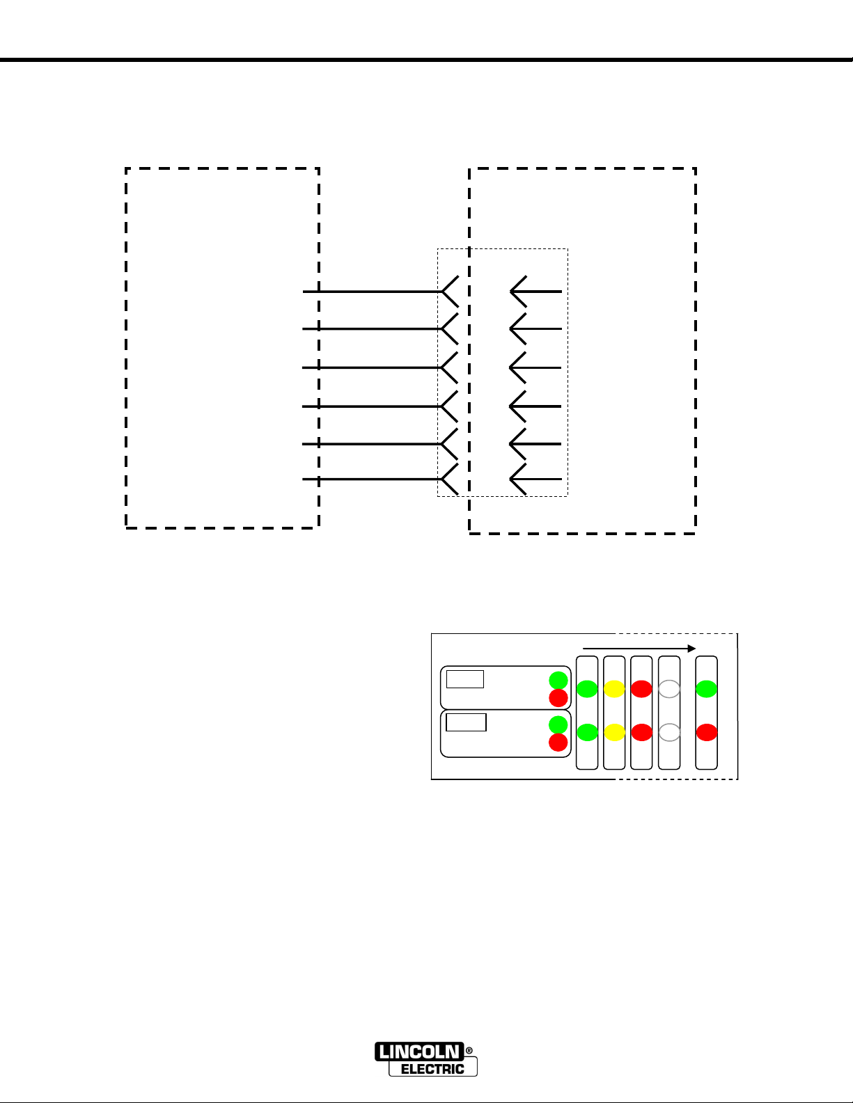
1 2 3 4 5
6
Wiring
1. 0V DC (WHT)
2. +24V DC (RED)
3. Complete (GRN)
4. Start (ORG)
5. Spray (BLK)
6. Error (BLU)
Interface Receptacle
Air Connection
Use only regulated, filtered, non lubricated air. Mount a 5 micron airline filter
(not supplied) in the airline of the reamer.
AIR SUPPLY REQUIREMENTS: 80 PSI at 15 SCFM. Connect the inlet
supply line to the quick connect pneumatic fitting located on the side of the
unit.
Electrical Connections
WARNING: Damage to equipment may occur if connected improperly.
Only a qualified technician should perform the following operation.
-Secure the 6-pin connector into the receptacle on the base of the POWER
REAM and feed the other end through a strain relief into the robot
controller cabinet or other connection points on the robotic cell.
-Connect robot I/O signals according to the following description.
Electrical Diagram
Wire Color Name Description
Red +24Vdc Power supply (+24Vdc, 0.5 amp)
White 0Vdc Power supply return.
It is recommended that power to the reamer be wired concurrent with robot servo power,
interrupt-able by an E-stop condition.
Orange Start Robot output. Pulse this
output from the robot for
0.5sec to start the ream cycle.
Black Spray Robot output. Pulse this
output from the robot for
approx. 0.5 sec while
positioned over the sprayer.
To activate the Wire Cutter,
turn on both the start and
spray outputs at the same
time or subsequently.
Green Complete Robot input. The robot should
check this input before and
after a reaming cycle.
Blue Error Robot input. The robot can
check this input after a
reaming cycle to ensure error
free operation. Refer to
Diagnostics section for error
codes.
The POWER REAM detects sinking or sourcing outputs from the robot and is capable of sinking
or sourcing signals to the robot. Before connecting ensure I/O configuration is compatible with
robot. POWER REAM factory setup is for robots with sinking outputs and active high inputs.
POWER REAM
Page 9
INSTALLATION - 9 -
G
G
Clamp
Open
Closed
Lift
Top
Bottom
R R G
G
Y Y R
R
G
R
WELDING
ROBOT CELL
WIRES IN
CONTROL PANEL
0V
+24V
*DI-3
*DO-3
*DO-4
*DI-4
POWER REAM
K2391-1 or similar
equipment
1 0V
2 +24V
3 Complete
4 Start
5 Spray
6 Error
2 WHITE
1 or 27 RED
4 GREEN
3 ORANGE
5 BLACK
6 BLUE
Power Ream to Lincoln Electric Welding Robot Cell
*These labels are for reference only.
Power Up Sequence: Once the unit is wired into
the robot and power is applied the LEDs will
display the power up sequence (green – yellow –
red) and then show positions of the cylinders
according to the legend next to the LED window.
If the LEDs are not reporting the clamp open and
the lift at the bottom then check the air pressure or
position sensors. If the LEDs are flashing red or
green check for start lock (see below). If the LEDs
are flashing yellow ensure the setup pushbutton is
not pressed or defective.
Start Lock: The start lock feature guards against a start signal present when the unit is powered up. If a
start signal is present, the POWER REAM will not cycle immediately after powering up. The LEDs will
display the power up sequence (green-yellow-red) and then flash green / red if an output from the robot is
present.
Robot Input: With the clamp open and the lift at the bottom, the ―complete‖ input to the robot will be on.
If it is not, the robot input type may need to be configured.
Robot Output: If by forcing on the ―Start‖ or ―Spray‖ output from the robot no action occurs, the robot
output type may need to be configured.
POWER REAM
Page 10
I/O Configuration - 10 -
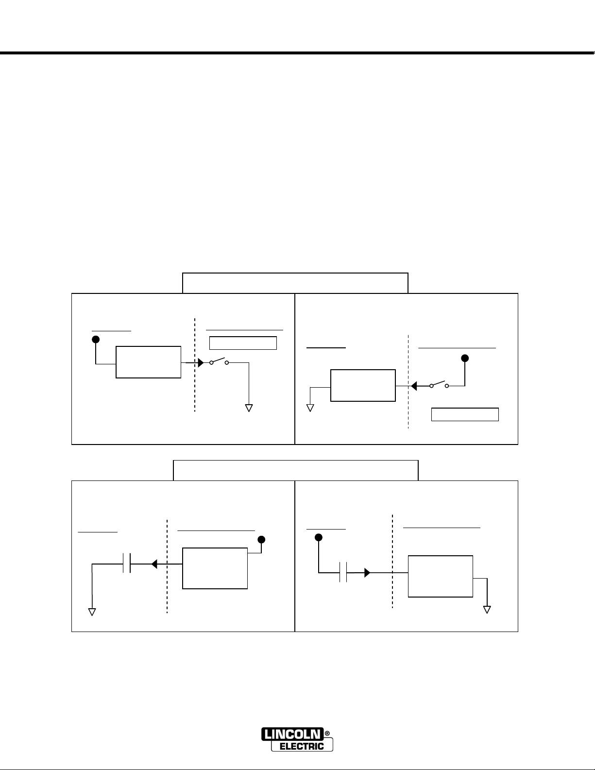
Sinking Output: 0V when active
Sourcing Output: +24V when active
Active Low Input: 0V when activated
Active High Input: +24V when activated
Fanuc robots use the following output methods
Process I/O: Sink Output
Terminal I/O: Source Output
Model A I/O: Source Output
ROBOT INPUT TYPE
+24V
ROBOT OUTPUT TYPE
Input
Circuitry
(< 1mA)
ROBOT
POWER REAM
SINKING
OUTPUT*
0V
+24V
Input
Circuitry
(<1mA)
ROBOT
POWER REAM
SOURCING
OUTPUT
0V
+24V
Input
Circuitry
ROBOT
POWER REAM
ACTIVE LOW
INPUT
0V
+24V
Input
Circuitry
ROBOT
POWER REAM
ACTIVE HIGH
INPUT*
0V
Max. current is 1A
Max. current is 1A
+24V
I/O Explanation
The terms sinking and sourcing define the direction of DC current flow in a load.
A sinking output provides a path to 0V for the load. Common terms used to describe sinking devices
include NPN, Open Collector, Active Low and IEC Negative Logic. An active low input is connected to
the positive supply (+24V) to detect a sinking output.
A sourcing output provides the power to the load. Common terms used to describe sourcing devices
include PNP, Open Emitter, Active High and IEC Positive Logic. An active high input is connected to 0V
to detect a sourcing output.
Factory set options: Active high robot input. Sinking robot output.
POWER REAM
Page 11
I/O Configuration - 11 -
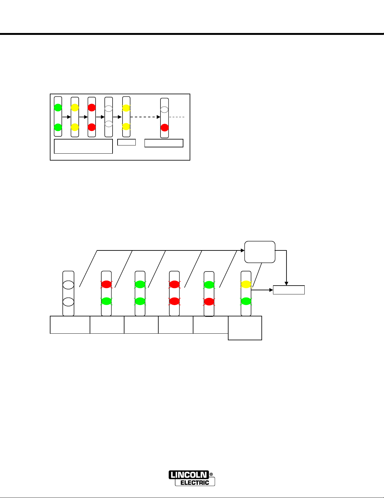
Power Up
Active High/
Sinking
Active Low/
Sinking
Active High/
Sourcing
Active Low/
Sourcing
AUTO
Active Low/
Sinking
Reset
button
PRESENT
Configuration
G G R
G
G
R R R Y G
G/R
G/R
(3 sec.)
Power up sequence
(1 sec.)
I/O configuration
-Release setup
pushbutton
Y Y R R R
G
G
Y
Y
The I/O types can be configured with the following procedure:
Press the reset and setup pushbuttons, release the reset pushbutton and continue to hold the
setup button for approximately 4 seconds (when the bottom LED is solid red).
During this time the LEDs will show the power-up sequence (green-yellow-red), then flash yellow for 3 seconds, then the bottom
LED will turn solid red. Release the setup button when the bottom LED is solid red. Continuing to hold the setup button will allow
access to further configurations as described in “Features Setup” section.
Upon releasing the setup push button, the lights will show the present I/O configuration. This is
the first in the sequence of teachable configurations.
Subsequent pressing and releasing of the setup button will sequence the following
configurations in order of appearance. To register the desired configuration, press the reset
button when that configuration is displayed.
The top indicator shows the robot input type (green = Active low, red = Active high*).
The bottom indicator shows the robot output type (green = Sinking*, red = Sourcing).
* Factory setup conditions
Auto Active Low/Sinking is for the automatic I/O configuration, setup as active low/sinking
initially (see automatic I/O configuration section for details). Choosing one of the other
configurations will disable this adaptability.
POWER REAM
Page 12

ROBOT PROGRAMMING - 12 -
―Complete‖ input
on?
Move to ―ream‖ position
Turn on ―Start‖ output
Move to ―wire cut‖
position
Inch wire for 0.5 sec.
Turn on ―spray‖ AND ― start‖ output
for 0.5 second.
Turn off ―start‖ and ―spray‖ outputs
Error
!
(at any time)
―Error‖ input
on?
Yes
No
Yes
Move to ―spray‖ position
Pulse ―spray‖ output for 0.5 second
Move to next position
Wait 0.5 sec
Turn off ―Start‖ output
Wait for ―Complete‖
input to turn on
The following flow diagram shows the recommended procedure for wire cutting, reaming, and
spraying sequences. Use the robot controller to implement this sequence.
POWER REAM
Page 13

ROBOT PROGRAMMING - 13 -
POWER REAM programming example for Fanuc robots
1: DO[28]=PULSE,.5SEC; Inch wire out for ½ second
2: CALL HOME; Safe home point position
3: IF DI[3]=OFF,JMP LBL[1]; Check if the reamer is ready
4: J P[1] 100% FINE; Safe approach point over wire cutter
5: L P[3] 500IPM FINE; Wire cut position (see illustration)
6: DO[3]=PULSE,.5SEC; Pulse reamer “start” signal, and…
7: DO[4]=PULSE,.5SEC; Pulse reamer “spray” signal to cut
8: WAIT .5SEC; Wait for the wire cutter
9: WAIT DI[3]=ON; Wait for reamer “complete” signal
10: L P[2] 500IPM FINE; Ream position (see illustration)
11: DO[3]=ON; Turn on reamer
12: WAIT 2SEC; Adjustable time for reaming operation
13: DO[3]=OFF; Turn off reamer
14: WAIT DI[3]=ON; Wait from reamer “complete” signal
15: L P[4] 500IPM FINE; Spray position (see illustration)
16: DO[4]=PULSE,.5SEC; Pulse anti-spatter spray
17: L P[5] 500IPM FINE; Pull out point from spray position
18: LBL[1]; Label for JMP statement, line 2
19: CALL HOME; Return to home point position
NOTE: The I/O points may be different, configuration specific.
How to teach reaming program instructions
CALL HOME; Press NEXT key, press F1 INST key, cursor to line CALL, Enter. At new
submenu, cursor to line Call Program, Enter. Now cursor to program
HOME, Enter.
DO[28]=PULSE,.5SEC; Press NEXT key, press F1 INST key, cursor to line I/O, Enter, cursor to
line DO=...., Enter, Key in (28), Enter, At new submenu, cursor to desired
line Pulse, Enter, key in desired time (.5), Enter.
IF DI[3]=OFF,JMP LBL[1]; Press NEXT, press F1 INST key, cursor to line IF/SELECT, Enter, cursor
to line IF?.=?., Enter, cursor to line DI, Enter, Key in 3, Enter, cursor to
OFF, Enter, cursor to JMP LBL, Enter Key in 1, Enter.
DO[3]=ON or OFF Press NEXT key, press F1 INST key, cursor to line I/O, Enter, cursor to
line DO[ ]=…, Enter, key in a 3, Enter, At new submenu, cursor to
desired line On or Off, Enter
WAIT 2SEC; Press NEXT key, cursor to line WAIT, Enter, at new submenu, cursor to
line WAIT… (sec), Enter, key in desired number of seconds, Enter.
WAIT DI[3]=ON; Press NEXT key, press F1 INST key, cursor to line WAIT, Enter, cursor
to line WAIT…, Enter. At new submenu, cursor to line DI[ ], Enter, key in
a 3, Enter. At new submenu, cursor to line ON, Enter.
DO[3]=PULSE,.3SEC; Press NEXT key, press F1 INST key, cursor to line I/O, Enter, cursor to
line DO[ ]=…, Enter, Key in desired output (3), Enter. At new submenu,
cursor to desired line Pulse, Enter, key in desired time (.5), Enter
POWER REAM
Page 14

ROBOT PROGRAMMING - 14 -
Robot Position Programming
The POWER REAM features a ―no trial, no error‖ position programming technique as described below:
1. Wire cut Position: Center the nozzle at the desired stick-out height above the wire cutter. Record this
position as the ―Wire Cut‖ position described in ―Robot Control Programming‖ section above.
2. Hold the ―Setup Sequencer‖ button to raise the reamer. This will lift the reamer without spinning.
WARNING: the lift will operate under this condition. KEEP HANDS CLEAR
of the operating space of the reamer. This device is intended for one-man
operation during setup.
Once the reamer is at the top position (―Lift‖ indicator is green), release the ―Setup
Sequencer‖ button.
3. Using the robot, move the torch nozzle into the clamp such that the reaming bit is inset to the full depth
required inside the nozzle.
4. Press and release the ―Setup Sequence‖ button to verify all four faces of the clamp engage the
cylindrical body of the nozzle equally, and that the nozzle does not change orientation or position when
clamped.
WARNING: the clamp will operate under this condition,
KEEP HANDS CLEAR of the operating space of the clamp
and wire cutter. This device is intended for one-man
operation during setup.
5. Register this position in the robot controller using a fine position level as the ―ream position‖ described
in flow diagram above.
6. Press the ―Reset‖ button until the reamer lowers. The reamer will lower without spinning, and the clamp
will open
WARNING: the lift and clamp will operate under this
condition. KEEP HANDS CLEAR of the operating space of
the reamer. This device is intended for one-man operation
during setup.
7. Spray Position: Center the nozzle 1½ inches above the spray head. Record this position as the
―Spray‖ position described in the flow diagram above.
Note: The fluid line takes approximately 10 seconds to prime. The sprayer has a built in post-flow timer of
1 second. Airflow from the nozzle will be present for 1 second after the spray output is turned off.
Wire Cut Position Ream Position Spray Position
POWER REAM
Page 15

OPERATION - 15 -
G R G
R
Clamp
Open
Closed
Lift
Top
Bottom
R R R Y R G R Y R R G R G
R
Ready
Clamp
Closed
Raising
Reamer
Reamer at
Top
Lowering
Reamer
Reamer at
Bottom
Clamp
Open
1 2 3 4 5 6 7
Pulse 0.5s
Off
Off
Off
Off
Off
On
Off
Off
Off
Off
Off
On
On
―Start‖ Output from robot
―Complete‖ Input to robot
Operation
The following diagram shows the 7-step reaming sequence and color of the indicator lights at each stage.
The indicator lights show the position of the clamp and lift cylinders on the user interface.
The above diagram shows the robot input and output as the sequence progresses.
Automatic Retry
If excessive spatter is built up in the nozzle, or programmed position of the nozzle is off center
not allowing reamer to extend to full depth within a specific amount of time, the POWER REAM
will automatically retry once.
Cycle Optimization
The lift rate of the reaming bit will determine how many reaming
revolutions will occur within the nozzle. This parameter should be
set based on the amount of spatter built up in the nozzle between
reaming cycles. More spatter buildup will require a slower lift rate.
Less spatter buildup will allow a faster lift rate.
To set the lift rate, remove the front cover and adjust the top
needle valve. Turning clockwise will decrease the lift rate (for more
spatter removal), and turning counter clockwise will increase the lift
rate.
To set the retracting rate, adjust the bottom needle. Turning
clockwise will decrease the retracting rate, and turning counter
clockwise will increase the retracting rate.
POWER REAM
Page 16

FEATURE SETUPS - 16 -
[Off]
[On]
[Off]
Power-up
Reset button
R Y G
3 sec
5 sec
7 sec
10 sec
Blow-off
Mode
I/O
Power-up
Press and Hold
Release
Setup
Press and Release
G G Y Y R
R
Y Y Y
Y
Power up sequence
Setup
Several features may be setup to optimize performance of the POWER REAM. To access the
configuration menus press the reset and setup pushbuttons, release the reset pushbutton and
continue to hold the setup button for the specified time shown below. The LEDs will change
color pattern to indicate the menu that is accessible at a specific time. Release the setup button
when the color pattern is shown for the desired configuration menu.
The default setting is first and last in the sequence of each configuration menu.
I/O configuration menu: See I/O configuration section on previous pages.
Blow-off: The motor spins and exhausts (blowing off over spray) for two seconds after spraying.
The blow-off feature can be configured by the following procedure.
Follow the steps outlined above to access the blow-off configuration menu. Upon releasing the
setup push button, the lights will flash red on top and blank on bottom. This is the first in the
sequence of teachable configurations.
Subsequent pressing and releasing of the setup button will sequence the following
configurations in order of appearance. To register the desired configuration, press the reset
button when that configuration is displayed.
Blow-off configurations;
Off: This feature is disabled.
On: This feature is enabled.
POWER REAM
Page 17

FEATURE SETUPS - 17 -
[Dry Run]
[Timed]
[Open]
[Blind]
[Automatic]
Power up
Reset
button
[Automatic]
G
G
Running Modes. Several running modes are available to select from.
Automatic: Every aspect of the operation is commanded, monitored and checked by the
controller.
Dry Run: Same as automatic mode, but the motor is disabled.
Timed: Bypass the "extended" sensor on the lift cylinder. The robot must hold the start signal
on for the reaming time. Auto Retry is disabled in this and the following modes.
Open: Bypass the "extended" and "retracted" sensor. The robot must hold the start signal on
for the reaming time and hold the robot in the clamp until the reaming bit is fully retracted.
Blind: Bypass all sensors. The robot must hold the start signal on for the ream time and hold
the torch in the jaws until the reaming bit is fully retracted and the clamp is fully opened.
Mode configuration: A specific running mode can be configured by the following procedure.
Follow the steps outlined above to access the mode configuration menu. Upon releasing the
setup push button, the lights will flash green on top and bottom. This is the first in the sequence
of teachable configurations.
Subsequent pressing and releasing of the setup button will sequence the following
configurations in order of appearance. To register the desired configuration, press the reset
button when that configuration is displayed.
POWER REAM
Page 18

AUTOMATIC I/O CONFIGURATION - 18 -
Power-up
―Complete‖
input on?
Turn on/off ―Spray‖ output
Sprayer
operates?
Turn off ―Spray‖ output.
I/O configuration complete
Turn OFF the ―Spray‖ signal.
Set I/O configuration using
the procedure outlined on
pg. 11
Yes
Yes
No
No
Power up sequence
G G G
R
Ready
Y Y R
R
G
R
Clamp
Open
Closed
Lift
Top
Bottom
R R G
G
Ensure the clamp is open
and the lift is at the bottom.
The LEDs on the control
panel should show the
following colors:
―Complete‖
input on?
Yes
Set I/O configuration using
the procedure outlined on
pg. 11
No
Automatic I/O configuration procedure:
The POWER REAM has an auto configuration I/O feature that is turned on by setting the I/O
configuration to AUTO (see I/O configuration section). The automatic I/O configuration works as
follows;
-The POWER REAM detects the type of robot input (active high / active low) when power is
applied or after resetting. Once detected, the POWER REAM outputs are configured.
-The POWER REAM senses and configures its inputs when the robot sends an output signal
(sinking or sourcing).
Use the following procedure to ensure that the POWER REAM is configured to the correct I/O
type using auto configuration. ―Spray‖ refers to the spray output from the robot and ―Complete‖
refers to the complete input to the robot.
CAUTION: the sprayer will operate in this procedure;
KEEP EYES AWAY from the sprayer
POWER REAM
Page 19

MAINTENANCE AND TROUBLESHOOTING - 19 -
Problem
Possible Cause
Solution
No Indicator lights
-Power is off
-Fuse is blown (robot cabinet)
-Reset button defective
-Circuit board defective
-Turn power on
-Replace fuse
-Replace reset button
-Replace circuit board
Reamer stops rotating
-Insufficient air supply
-Excessive spatter buildup
-Dry run mode selected
-Set to 80psi
-Ream more often
-Select automatic mode
Clamp/Motor/Lift not working
-Insufficient air supply
-Air line cut or twisted
-Reset button defective
-Check error codes
-Set to 80psi min
-Replace airline
-Replace reset button
Reamer does not go down
-Ream bit jammed in nozzle
-Lift cylinder defective
-Top sensor defective
-―Start‖ output held on
-Check error codes
-Replace damaged parts
-Replace lift cylinder
-Replace top sensor
-Pulse ―Start‖ output 0.5 sec
Robot cannot start a cycle
or
Robot cannot complete a cycle
- ―Complete‖ signal not
responding
-Check error codes
No Anti-Spatter liquid
Or air flow from sprayer
-Insufficient air supply
-Solenoid valve defective
-Spray nozzle clogged
-Set to 80psi
-Replace solenoid valve
-Clean or replace spray nozzle
*hand tighten only
Air flow from sprayer but
no Anti-Spatter liquid
-Check anti-spatter level
-Check vent on reservoir
-Fluid line blocked
-Spray nozzle clogged
-Refill reservoir
-Open vent if closed
-Clean or repair fluid line
-Clean or replace spray nozzle
*hand tighten only
MAINTENANCE
The POWER REAM will require periodic maintenance to ensure a dependable service life. The following
schedule is recommended.
Shut off the air supply and disconnect robot control cable when making adjustments.
DAILY
• Clean surface under reaming bit.
• Check airlines for leaks and robot control cable for splits or cracks.
• Clean clamp gripping surfaces to ensure optimal nozzle gripping.
WEEKLY
• Check the fluid level in spray reservoir.
• Check the reaming bit visually.
• Check the wire cutter visually.
The service life of the cutting edges are dependant on the type of application. Inspect for dullness and
possible breakage.
YEARLY
• Inspect drive belt for wear and tension. Replace if excessive wear is evident.
TROUBLESHOOTING
POWER REAM
Page 20

Diagnostics - 20 -
2: Closing Fault: the clamp took too long to close.
-Check air inlet pressure
-Check clamp sensor
-Check clamp air lines
-Check clamp solenoid.
-Check clamp cylinder
3: Raising Fault: The lift cylinder took too long to extend from the bottom limit
-Check air inlet pressure
-Check extending needle valve (top needle valve on lift cylinder)
-Check bottom sensor.
-Check lift air lines
-Check lift solenoid.
-Check lift cylinder
4: Extending Fault: The lift cylinder took too long to fully extend.
-Automatic retry; excessive spatter build up in the nozzle (ream more often), or incorrect programmed position of
the nozzle, not allowing reamer to extend to full depth.
-Check air inlet pressure
-Check extending needle valve (top needle valve on lift cylinder)
-Check top sensor.
-Check lift air lines
-Check lift solenoid.
-Check lift cylinder
5: Lowering Fault: The lift cylinder took too long to retract from the top while lowering
-Check air inlet pressure
-Check retracting needle valve (bottom needle valve on lift cylinder)
-Check top sensor.
-Check lift airlines.
-Check lift solenoid.
-Check lift cylinder.
6: Retracting Fault: The lift cylinder took too long to fully retract.
-Check air inlet pressure
-Check retracting needle valve (bottom needle valve on lift cylinder)
-Check bottom sensor.
-Check lift airlines.
-Check lift solenoid.
-Check lift cylinder.
7: Opening Fault: the clamp took too long to open.
-Check air inlet pressure
-Check clamp sensor.
-Check clamp cylinder airlines.
-Check clamp solenoid.
-Check clamp cylinder.
Y
The POWER REAM reports errors using the indicator lights on the user interface
When an error is reported, the indicator light flashes at a rate of 2 flashes per second
Error: When an error occurs during the reaming process; the clamp opens, the lift lowers, and the
diagnosis is shown with the top indicator light in yellow. The light will flash a certain number of times,
pause, then repeat. The error count begins at 2.
Count the number of flashes between the pause and use the following chart to find the cause of the
problem.
Note: The robot ―start‖ signal may be used to reset an error so that the operator does not have to go
inside the robotic welding cell. For example, if the air supply was not turned on the operator may turn it
on and reset the error by cycling the start output from the robot pendant.
POWER REAM
Page 21

Parts Replacement - 21 -
1 2 3
4
1
Reaming Bit Replacement
Disconnect air and electrical supply.
Hold the reaming rod, item 1, from
rotating with 5/8‖ wrench under the
washer.
Unfasten the reaming bit, item 2,
with a second 5/8‖ wrench.
Remove the reaming bit, item 3.
Insert the new reaming bit through
the flat washer, item 4.
Insert the reaming bit into the ream
rod.
Hold the reaming rod from rotating
with a 5/8‖ wrench under the
washer.
Tighten the reaming bit with a
second 5/8‖ wrench.
Reconnect air and electrical supply.
Spray Nozzle Replacement
Disconnect air and electrical supply.
Unscrew spray nozzle, item 1, by
hand.
Insert new spray nozzle.
TIGHTEN BY HAND ONLY
Reconnect air and electrical supply.
POWER REAM
Page 22

Parts Replacement - 22 -
1
4 2 3
1
2
Wire Cutter Replacement
Disconnect air and electrical supply.
Unfasten (4) #8-32 flat head socket
cap screws, item 1.(3/32‖ hex drive)
Remove wire cutter module, item 2.
Insert new wire cutter module.
NOTE: The cutters will close slightly
when positioning the rollers against the
wedge.
Fasten (4) #8-32 flat head socket
cap screws, item 1. Apply medium
strength threadlocker. (3/32‖ hex
drive)
Reconnect air and electrical supply.
PC Board Replacement
Disconnect air and electrical supply.
Loosen (6) button head cap screws ,
item 1, to remove rear cover.
(5/32‖ hex drive)
Remove (7) connectors, item 2,
from PC board.
Remove (5) #6-32 socket head cap
screws, item 3, from PC board.
(7/64‖ hex drive)
Remove PC board, item 4.
Insert new PC board.
Follow steps in reverse order to
reassemble unit.
POWER REAM
Page 23

Parts Replacement - 23 -
9
10
1
2
3 4 5 6 8
7
Belt Replacement
Disconnect air, item 1,
and electrical supply, item2.
Loosen (6) button head cap
screws, item 3, to remove rear
cover. (5/32‖ hex drive)
Check and note the belt tension, item 4.
Remove (2) 6mm hex head bolts,
item 5. (10 mm wrench)
Slide motor forward to slip belt off
motor gear and remove motor,
item 6.
Remove (4) button head cap screws,
item 7, to remove front cover
(5/32‖ hex drive)
Remove (4) socket head cap screws
and lock washers, item 8, from
bottom plate of motor carriage.
(3/16‖ hex drive)
Remove (2) side plates, item 9.
Lift up on the front gear, slip belt off
and remove belt, item 10.
Lift up on the front gear, slip new
belt over front gear.
Follow steps in reverse order to
reassemble unit.
Apply medium strength threadlocker
to item 5.
POWER REAM
Page 24

Parts Replacement - 24 -
4
1 2 5 3 6 5 4 3 2
1
Air Motor Replacement
Disconnect air and electrical supply.
Loosen (6) button head cap screws,
item 1, to remove rear cover.
(5/32‖ hex drive)
Disconnect hoses 111 and 112,
item 2, from the motor.
Check and note the belt tension,
item 3.
Hold the motor from below and
remove (2) 6mm hex head bolts,
item 4. (10mm wrench)
Slip belt off motor gear and remove
motor, item 5.
Insert new motor into mount.
Follow steps in reverse order to
reassemble unit.
Apply medium strength threadlocker
to item 4.
Motor Solenoid Replacement
Disconnect air and electrical supply.
Loosen (6) button head cap screws,
item 1, to remove rear cover.
Remove electrical connector, item 2,
from motor solenoid.
(Star screwdriver)
Disconnect hose 111, item 3,from
motor solenoid.
Remove (2) #8-32 socket head cap
screws, item 4, from solenoid.
(9/64‖ hex drive)
Remove motor solenoid, item 5.
Disconnect hose 110, item 6,from
motor solenoid.
Follow steps in reverse order to
reassemble unit.
POWER REAM
Page 25

Parts Replacement - 25 -
7
1 2 3 4 5
6
Lift\Clamp Solenoid Replacement
Note: The lift and clamp cylinder solenoids are stacked. The top solenoid is for the clamp cylinder, the
bottom solenoid is for the lift cylinder. Similar procedures are used for each solenoid.
Disconnect air and electrical supply.
Loosen (6) button head cap screws,
item 1, to remove rear cover.
(5/32‖ hex drive)
Lift Solenoid: Disconnect hose 130
from solenoid in-port, item 2.
Clamp Solenoid: Disconnect hose
120, item 3, from solenoid in-port.
Remove(2) #4-40 socket head cap
screws, item 4, from solenoids.
(3/32‖ hex drive)
Remove electrical connector, item 5,
from solenoid. (star screwdriver)
Lift Solenoid: Disconnect hose 131
and 132 from solenoid out-port,
item 6.
Clamp Solenoid: Disconnect hose
121 and 122 from solenoid out-port,
item 7.
Remove solenoid, insert new
solenoid.
Follow steps in reverse order to
reassemble unit.
POWER REAM
Page 26

Parts Replacement - 26 -
6 8 1 4 5 3 2
Clamp Cylinder Replacement
Disconnect air and electrical supply.
Loosen (6) button head cap screws,
item 1, to remove rear cover.
Remove (6) socket head cap
screws, item 2, to remove top
cover.(3/16‖ hex drive).
Disconnect hose 121 and 122,
item 3, from cylinder in-ports.
Remove reed switch, item 4, from
cylinder.(5/64‖ hex drive)
Remove (2) #10-24 flat head socket
cap screws, item 5, to remove
wedge plate. (1/8‖ hex drive)
Unfasten cylinder rod, item 6, from
T-nut. (3/8‖ wrench)
Loosen and remove cylinder nut,
item 7, (1 1/8‖ wrench)
Remove cylinder, item 8.
Follow steps in reverse order to
reassemble unit.
Apply medium strength threadlocker
to item 5, 6 and 7.
Check the position of
reed switch, item 4. The led
should be on when the clamp is
open with electrical supply
connected.
POWER REAM
Page 27

Parts Replacement - 27 -
1 3 4 5 6
7
1
10
2
Spray Solenoid Replacement
Disconnect air and electrical supply.
Loosen (6) button head cap screws,
item 1, to remove rear cover.
Remove (2) wires, item 2, from
10-position connector
(pins 9 and 10 at the bottom).
Pull wires, item 3, through the hole
in main unit to the outside.
Unfasten bottom nut, item 4, of
compression fitting. (9/16‖ wrench)
DO NOT REMOVE
Remove (2) #4-40 socket head cap
screws, item 5, from spray solenoid.
(3/32‖ hex drive)
Raise spray solenoid valve while
detaching plastic fitting, item 6, from
the side.
Remove spray solenoid, item 7.
Follow steps in reverse order to
reassemble unit.
When tightening bottom nut, item 4,,
DO NOT OVER TIGHTEN
POWER REAM
Page 28

Parts Replacement - 28 -
1 2 3 4 5 6 7
Fluid Solenoid Replacement
Disconnect air and electrical supply.
Remove anti spatter fluid reservoir,
item 1. (3/4‖ wrench)
WARNING: Contents may spill.
Remove bottom nut, item 2, of
compression fitting. (9/16‖ wrench)
Remove electrical connector, item 3,
from fluid solenoid valve.
(star screwdriver)
Remove (2) 4-40 socket head cap
screws, item 4, from spray solenoid.
(3/32‖ hex drive)
Remove (2) #8-32 socket head cap
screws, item 5, from spray assembly
plate. (9/64‖ hex drive)
Raise spray plate item 6.
Remove (2) 3mm socket head cap
screws, item 7, from back of spray
assembly plate and replace fluid
solenoid. (3/32‖ hex drive)
Follow steps in reverse order to
reassemble unit.
When tightening bottom nut, item 2,
DO NOT OVER TIGHTEN
POWER REAM
Page 29

PNEUMATIC DIAGRAM - 29 -
112
R1
P
B
A
R2
R2
A
P
R1
B
111
110
100
120
130
140
121
122
131
132
Note: All locations are referenced from the back of the unit
Additional pneumatic troubleshooting information:
Air enters the unit through hose 100 and is distributed to the solenoids through the manifold
Hose 110 feeds the motor solenoid. Air flows through hose 111 and 112 when the motor is on.
Hose 120 feeds the clamp solenoid. Hose 121 is normally pressurized, keeping the clamp in the open
position. When the clamp is closed hose 122 become pressurized. Air flows through lines 121, 122,
and out the breather vents of the clamp solenoid when opening or closing.
Hose 130 feeds the lift solenoid. Hose 131 is normally pressurized, keeping the lift in the bottom
position. When the lift is raised hose 132 becomes pressurized. Air flows through lines 131, 132, and
out the breather vents of the lift solenoid when raising or lowering
Hose 140 feeds the spray solenoid. Air flows through the tubing when the sprayer is on.
POWER REAM
Page 30

ELECTRICAL DIAGRAM - 30 -
Note: All locations are referenced
from the back of the unit
POWER REAM
Page 31

ELECTRICAL DIAGRAM - 31 -
Wire #
Description
Active
Voltage
Inactive
Voltage
101 to 102
Start output from robot
24V sourcing
0V sinking
0V sourcing
24V sinking
12V auto detect
103 to 102
24V power
24V
0V
104 to 102
Finished input to robot
24V sourcing
0V sinking
Floating
105 to 102
Spray output from robot
24V sourcing
0V sinking
0V sourcing
24V sinking
12V auto detect
106 to 102
Error input to robot
24V sourcing
0V sinking
Floating
201 to 203
Extended reed sensor
1.5V
23.3V
301 to 302
Retracted reed sensor
1.5V
23.3V
502 to 501
Fluid solenoid
24V
0V
504 to 503
Motor solenoid
24V
0V
506 to 505
Lift solenoid
24V
0V
508 to 507
Clamp solenoid
24V
0V
510 to 509
Spray solenoid
24V
0V
601 to 602
Setup pushbutton
0V
5V
604 to 603
Reset pushbutton
0V
5V
Additional electrical troubleshooting information:
Use the wire numbers in the following table to take readings with a voltmeter.
Connect the (+) lead to the first wire number and the (-) lead to the second wire number.
Note: all voltage readings +/- 10%
POWER REAM
Page 32

PARTS DIAGRAM - 32 -
4
1
2
3
ITEM
PART #
DESCRIPTION
1
G4827-3
CLAMP ASSEMBLY
2
G4827-4
WEDGE ASSEMBLY
3
G4827-5
CLAMP CYLINDER ASSEMBLY
4
G4827-6
WIRE CUTTER ASSEMBLY
POWER REAM
TABLE 2
Page 33

PARTS DIAGRAM - 33 -
14
10a
11a
15a
15b
9a
5a
6
7
10
11
12
15
13
9
8
5
ITEM
PART #
DESCRIPTION
5
G4827-7
FLUID RESERVOIR ASSEMBLY
5A
G4827-8
RESERVOIR LID
6
G4827-9
FLUID SOLENOID ASSEMBLY
7
G4827-10
SPRAY SOLENOID ASSEMBLY
8
KP2435-4
REAMING BIT, 5/8‖ (W/WASHER)
8A
G4827-1
REAMING BIT WASHER
9
G4827-11
SPRAY NOZZLE ASSEMBLY
9A
G4827-12
SPRAY NOZZLE
10
G4827-13
DOME ASSEMBLY
10A
G4827-14
ROD WIPER SEAL
11
G4827-15
CARRIAGE ASSEMBLY
11a
G4827-16
TIMING BELT
12
G4827-17
LIFT CYLINDER ASSEMBLY
13
G4827-18
EXTENDED SENSOR ASSEMBLY
14
G4827-19
RETRACTED SENSOR ASSEMBLY
15
G4827-20
FRAME ASSEMBLY
15A
G4827-21
FRONT COVER
15B
G4827-22
BACK COVER
POWER REAM
Page 34

PARTS DIAGRAM - 34 -
21
19
24
16
18
20
17
25
22
23
26
ITEM
PART #
DESCRIPTION
16
G4827-23
OPEN SENSOR ASSEMBLY
17
G4827-24
EXHAUST MUFFLER ASSEMBLY
18
G4827-25
RESET PUSHBUTTON ASSEMBLY
29
G4827-26
MOTOR SOLENOID ASSEMBLY
20
G4827-27
P.C. BOARD W/ MICROCONTROLLER
21
G4827-28
SETUP PUSHBUTTON ASSEMBLY
22
G4827-29
AIR MOTOR ASSEMBLY
23
G4827-30
AIR DISTRIBUTION ASSEMBLY
24
G4827-31
ROBOT CONNECTOR ASSEMBLY
24A
K2433-1
POWER REAM ROBOT CABLE, 20 FT
25
G4827-32
CYLINDER SOLENOID ASSEMBLY (2)
26
S23044
PNEUMATIC FITTING (1/4 ― NPT)
POWER REAM
Page 35

OPTIONAL ACCESSORIES - 35 -
PART NO.
DESCRIPTION
KP2435-1
REAMING BIT, ½‖ (W/WASHER)
KP2435-3
REAMING BIT, 5/8‖ (15.5mm) (W/WASHER)
KP2435-5
REAMING BIT, ¾‖ (W/WASHER)
KP2457-1
ANTI SPATTER FLUID, 1 GALLON
K2433-1
POWER REAM ROBOT CABLE, 20FT
K2434-1
REMOTE POWER REAM RESERVOIR KIT
S22633-50
CONNECTOR, PLUG, HONDA, 50 SOCKET
S22510-1
CONNECTOR, COVER, HONDA, STRAIGHT, 50 PIN
POWER REAM
Page 36

• Sales and Service through Subsidiaries and Distributors Worldwide •
Cleveland, Ohio 44117-1199 U.S.A. TEL: 216.481.8100 FAX: 216.486.1751 WEB SITE: www.lincolnelectric.com
• World's Leader in Welding and Cutting Products •
 Loading...