

Page 1
IM837-A
RETURN TO MAIN MENU
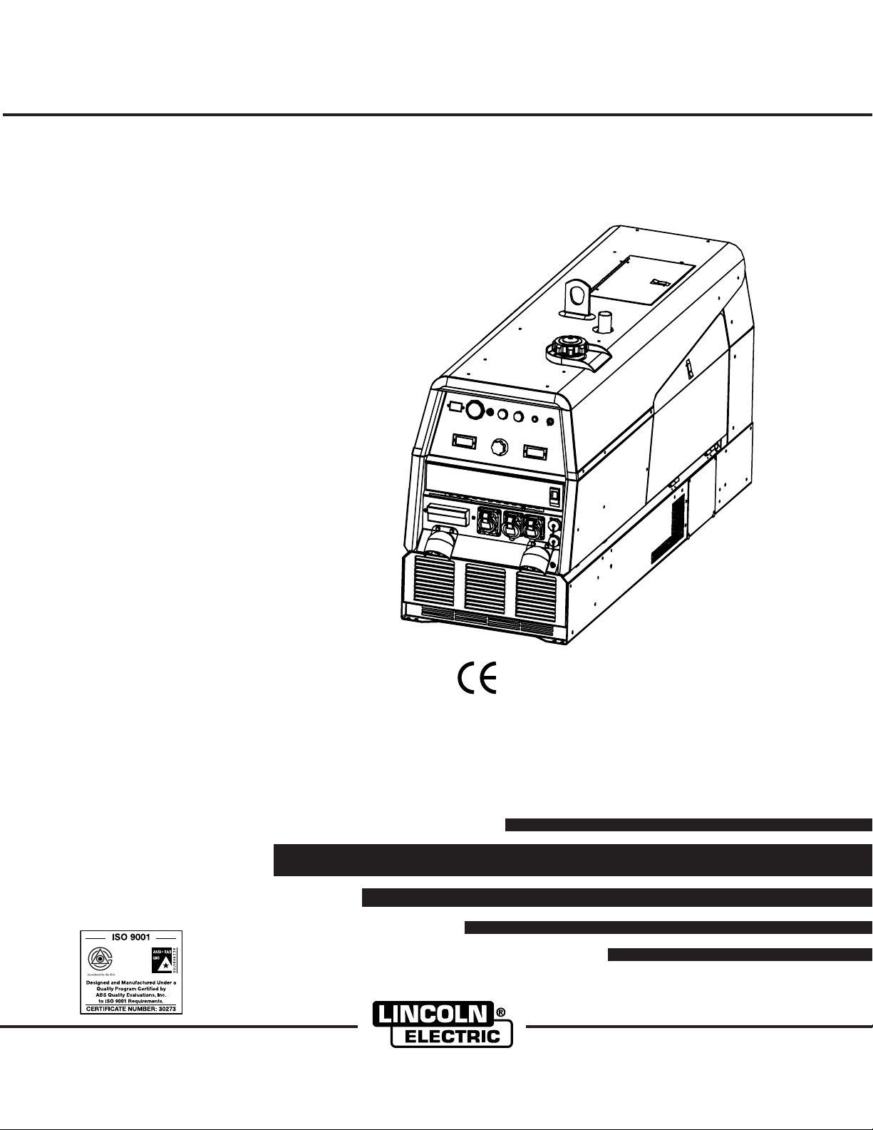
Ranger 305 D (CE)
For use with machines having Code Numbers:
Safety Depends on You
Lincoln arc welding and cutting
equipment is designed and built
with safety in mind. However, your
overall safety can be increased by
proper installation ... and thoughtful operation on your part. DO
NOT INSTALL, OPERATE OR
REPAIR THIS EQUIPMENT
WITHOUT READING THIS
MANUAL AND THE SAFETY
PRECAUTIONS CONTAINED
THROUGHOUT. And, most
importantly, think before you act
and be careful.
June, 2005
11122, 11123, 11189, 11190
Cleveland, Ohio 44117-1199 U.S.A. TEL: 216.481.8100 FAX: 216.486.1751 WEB SITE: www.lincolnelectric.com
EN 60974-1
OPERATOR’S MANUAL
Copyright © 2005 Lincoln Global Inc.
• World's Leader in Welding and Cutting Products •
• Sales and Service through Subsidiaries and Distributors Worldwide •
Page 2
i
SAFETY
i
WARNING
CALIFORNIA PROPOSITION 65 WARNINGS
Diesel engine exhaust and some of its constituents
are known to the State of California to cause cancer, birth defects, and other reproductive harm.
The Above For Diesel Engines
ARC WELDING CAN BE HAZARDOUS. PROTECT YOURSELF AND OTHERS FROM POSSIBLE SERIOUS INJURY OR DEATH.
KEEP CHILDREN AWAY. PACEMAKER WEARERS SHOULD CONSULT WITH THEIR DOCTOR BEFORE OPERATING.
Read and understand the following safety highlights. For additional safety information, it is strongly recommended that you
purchase a copy of “Safety in Welding & Cutting - ANSI Standard Z49.1” from the American Welding Society, P.O. Box
351040, Miami, Florida 33135 or CSA Standard W117.2-1974. A Free copy of “Arc Welding Safety” booklet E205 is available
from the Lincoln Electric Company, 22801 St. Clair Avenue, Cleveland, Ohio 44117-1199.
BE SURE THAT ALL INSTALLATION, OPERATION, MAINTENANCE AND REPAIR PROCEDURES ARE
PERFORMED ONLY BY QUALIFIED INDIVIDUALS.
The engine exhaust from this product contains
chemicals known to the State of California to cause
cancer, birth defects, or other reproductive harm.
The Above For Gasoline Engines
FOR ENGINE
powered equipment.
1.a. Turn the engine off before troubleshooting and maintenance
work unless the maintenance work requires it to be running.
____________________________________________________
1.b.Operate engines in open, well-ventilated
areas or vent the engine exhaust fumes
outdoors.
____________________________________________________
1.c. Do not add the fuel near an open flame
welding arc or when the engine is running.
Stop the engine and allow it to cool before
refueling to prevent spilled fuel from vaporizing on contact with hot engine parts and
igniting. Do not spill fuel when filling tank. If
fuel is spilled, wipe it up and do not start
engine until fumes have been eliminated.
____________________________________________________
1.d. Keep all equipment safety guards, covers and devices in
position and in good repair.Keep hands, hair, clothing and
tools away from V-belts, gears, fans and all other moving
parts when starting, operating or repairing equipment.
____________________________________________________
1.e. In some cases it may be necessary to remove safety
guards to perform required maintenance. Remove
guards only when necessary and replace them when the
maintenance requiring their removal is complete.
Always use the greatest care when working near moving
parts.
___________________________________________________
1.f. Do not put your hands near the engine fan.
Do not attempt to override the governor or
idler by pushing on the throttle control rods
while the engine is running.
1.h. To avoid scalding, do not remove the
radiator pressure cap when the engine is
hot.
ELECTRIC AND
MAGNETIC FIELDS
may be dangerous
2.a. Electric current flowing through any conductor causes
localized Electric and Magnetic Fields (EMF). Welding
current creates EMF fields around welding cables and
welding machines
2.b. EMF fields may interfere with some pacemakers, and
welders having a pacemaker should consult their physician
before welding.
2.c. Exposure to EMF fields in welding may have other health
effects which are now not known.
2.d. All welders should use the following procedures in order to
minimize exposure to EMF fields from the welding circuit:
2.d.1.
Route the electrode and work cables together - Secure
them with tape when possible.
2.d.2. Never coil the electrode lead around your body.
2.d.3. Do not place your body between the electrode and
work cables. If the electrode cable is on your right
side, the work cable should also be on your right side.
___________________________________________________
1.g. To prevent accidentally starting gasoline engines while
turning the engine or welding generator during maintenance
work, disconnect the spark plug wires, distributor cap or
magneto wire as appropriate.
2.d.4. Connect the work cable to the workpiece as close as
possible to the area being welded.
2.d.5. Do not work next to welding power source.
Mar ‘95
Page 3
ii
SAFETY
ii
ELECTRIC SHOCK can
kill.
3.a. The electrode and work (or ground) circuits
are electrically “hot” when the welder is on.
Do not touch these “hot” parts with your bare
skin or wet clothing. Wear dry, hole-free
gloves to insulate hands.
3.b. Insulate yourself from work and ground using dry insulation.
Make certain the insulation is large enough to cover your full
area of physical contact with work and ground.
In addition to the normal safety precautions, if welding
must be performed under electrically hazardous
conditions (in damp locations or while wearing wet
clothing; on metal structures such as floors, gratings or
scaffolds; when in cramped positions such as sitting,
kneeling or lying, if there is a high risk of unavoidable or
accidental contact with the workpiece or ground) use
the following equipment:
• Semiautomatic DC Constant Voltage (Wire) Welder.
• DC Manual (Stick) Welder.
• AC Welder with Reduced Voltage Control.
3.c. In semiautomatic or automatic wire welding, the electrode,
electrode reel, welding head, nozzle or semiautomatic
welding gun are also electrically “hot”.
3.d. Always be sure the work cable makes a good electrical
connection with the metal being welded. The connection
should be as close as possible to the area being welded.
3.e. Ground the work or metal to be welded to a good electrical
(earth) ground.
ARC RAYS can burn.
4.a. Use a shield with the proper filter and cover
plates to protect your eyes from sparks and
the rays of the arc when welding or observing
open arc welding. Headshield and filter lens
should conform to ANSI Z87. I standards.
4.b. Use suitable clothing made from durable flame-resistant
material to protect your skin and that of your helpers from
the arc rays.
4.c. Protect other nearby personnel with suitable, non-flammable
screening and/or warn them not to watch the arc nor expose
themselves to the arc rays or to hot spatter or metal.
FUMES AND GASES
can be dangerous.
5.a.Welding may produce fumes and gases
hazardous to health. Avoid breathing these
fumes and gases.When welding, keep
your head out of the fume. Use enough
ventilation and/or exhaust at the arc to keep
fumes and gases away from the breathing zone. When
welding with electrodes which require special
ventilation such as stainless or hard facing (see
instructions on container or MSDS) or on lead or
cadmium plated steel and other metals or coatings
which produce highly toxic fumes, keep exposure as
low as possible and below Threshold Limit Values (TLV)
using local exhaust or mechanical ventilation. In
confined spaces or in some circumstances, outdoors, a
respirator may be required. Additional precautions are
also required when welding on galvanized steel.
3.f.
Maintain the electrode holder, work clamp, welding cable and
welding machine in good, safe operating condition. Replace
damaged insulation.
3.g. Never dip the electrode in water for cooling.
3.h. Never simultaneously touch electrically “hot” parts of
electrode holders connected to two welders because voltage
between the two can be the total of the open circuit voltage
of both welders.
3.i. When working above floor level, use a safety belt to protect
yourself from a fall should you get a shock.
3.j. Also see Items 6.c. and 8.
5.b.
Do not weld in locations near chlorinated hydrocarbon
coming from degreasing, cleaning or spraying operations.
The heat and rays of the arc can react with solvent vapors to
form phosgene, a highly toxic gas, and other irritating products.
5.c. Shielding gases used for arc welding can displace air and
cause injury or death. Always use enough ventilation,
especially in confined areas, to insure breathing air is safe.
5.d. Read and understand the manufacturer’s instructions for this
equipment and the consumables to be used, including the
material safety data sheet (MSDS) and follow your
employer’s safety practices. MSDS forms are available from
your welding distributor or from the manufacturer.
5.e. Also see item 1.b.
vapors
Mar ‘95
Page 4
iii
SAFETY
iii
WELDING SPARKS can
cause fire or explosion.
6.a.
Remove fire hazards from the welding area.
If this is not possible, cover them to prevent
the welding sparks from starting a fire.
materials from welding can easily go through small cracks
and openings to adjacent areas. Avoid welding near
hydraulic lines. Have a fire extinguisher readily available.
6.b. Where compressed gases are to be used at the job site,
special precautions should be used to prevent hazardous
situations. Refer to “Safety in Welding and Cutting” (ANSI
Standard Z49.1) and the operating information for the
equipment being used.
6.c. When not welding, make certain no part of the electrode
circuit is touching the work or ground. Accidental contact
can cause overheating and create a fire hazard.
6.d. Do not heat, cut or weld tanks, drums or containers until the
proper steps have been taken to insure that such procedures
will not cause flammable or toxic vapors from substances
inside. They can cause an explosion even
been “cleaned”. For information, purchase “Recommended
Safe Practices for the
Containers and Piping That Have Held Hazardous
Substances”, AWS F4.1 from the American Welding Society
(see address above).
6.e. Vent hollow castings or containers before heating, cutting or
welding. They may explode.
Sparks and spatter are thrown from the welding arc. Wear oil
6.f.
free protective garments such as leather gloves, heavy shirt,
cuffless trousers, high shoes and a cap over your hair. Wear
ear plugs when welding out of position or in confined places.
Always wear safety glasses with side shields when in a
welding area.
6.g. Connect the work cable to the work as close to the welding
area as practical. Work cables connected to the building
framework or other locations away from the welding area
increase the possibility of the welding current passing
through lifting chains, crane cables or other alternate circuits. This can create fire hazards or overheat lifting chains
or cables until they fail.
6.h. Also see item 1.c.
Remember that welding sparks and hot
though
they have
Preparation
for Welding and Cutting of
CYLINDER may explode
if damaged.
7.a. Use only compressed gas cylinders
containing the correct shielding gas for the
process used and properly operating
regulators designed for the gas and
pressure used. All hoses, fittings, etc. should be suitable for
the application and maintained in good condition.
7.b. Always keep cylinders in an upright position securely
chained to an undercarriage or fixed support.
7.c. Cylinders should be located:
•Away from areas where they may be struck or subjected to
physical damage.
• A safe distance from arc welding or cutting operations and
any other source of heat, sparks, or flame.
7.d. Never allow the electrode, electrode holder or any other
electrically “hot” parts to touch a cylinder.
7.e. Keep your head and face away from the cylinder valve outlet
when opening the cylinder valve.
7.f. Valve protection caps should always be in place and hand
tight except when the cylinder is in use or connected for
use.
7.g. Read and follow the instructions on compressed gas
cylinders, associated equipment, and CGA publication P-l,
“Precautions for Safe Handling of Compressed Gases in
Cylinders,” available from the Compressed Gas Association
1235 Jefferson Davis Highway, Arlington, VA 22202.
FOR ELECTRICALLY
powered equipment.
8.a. Turn off input power using the disconnect
switch at the fuse box before working on
the equipment.
8.b. Install equipment in accordance with the U.S. National
Electrical Code, all local codes and the manufacturer’s
recommendations.
8.c. Ground the equipment in accordance with the U.S. National
Electrical Code and the manufacturer’s recommendations.
Mar ‘95
Page 5

iv
SAFETY
iv
PRÉCAUTIONS DE SÛRETÉ
Pour votre propre protection lire et observer toutes les instructions et les précautions de sûreté specifiques qui parraissent
dans ce manuel aussi bien que les précautions de sûreté
générales suivantes:
Sûreté Pour Soudage A L’Arc
1. Protegez-vous contre la secousse électrique:
a. Les circuits à l’électrode et à la piéce sont sous tension
quand la machine à souder est en marche. Eviter toujours
tout contact entre les parties sous tension et la peau nue
ou les vétements mouillés. Porter des gants secs et sans
trous pour isoler les mains.
b. Faire trés attention de bien s’isoler de la masse quand on
soude dans des endroits humides, ou sur un plancher
metallique ou des grilles metalliques, principalement dans
les positions assis ou couché pour lesquelles une
grande partie du corps peut être en contact avec la
masse.
c. Maintenir le porte-électrode, la pince de masse, le câble
de soudage et la machine à souder en bon et sûr état
defonctionnement.
d.Ne jamais plonger le porte-électrode dans l’eau pour le
refroidir.
e. Ne jamais toucher simultanément les parties sous tension
des porte-électrodes connectés à deux machines à souder parce que la tension entre les deux pinces peut être le
total de la tension à vide des deux machines.
f. Si on utilise la machine à souder comme une source de
courant pour soudage semi-automatique, ces precautions
pour le porte-électrode s’applicuent aussi au pistolet de
soudage.
5. Toujours porter des lunettes de sécurité dans la zone de
soudage. Utiliser des lunettes avec écrans lateraux dans les
zones où l’on pique le laitier.
6. Eloigner les matériaux inflammables ou les recouvrir afin de
prévenir tout risque d’incendie dû aux étincelles.
7. Quand on ne soude pas, poser la pince à une endroit isolé de
la masse. Un court-circuit accidental peut provoquer un
échauffement et un risque d’incendie.
8. S’assurer que la masse est connectée le plus prés possible
de la zone de travail qu’il est pratique de le faire. Si on place
la masse sur la charpente de la construction ou d’autres
endroits éloignés de la zone de travail, on augmente le risque
de voir passer le courant de soudage par les chaines de levage, câbles de grue, ou autres circuits. Cela peut provoquer
des risques d’incendie ou d’echauffement des chaines et des
câbles jusqu’à ce qu’ils se rompent.
9. Assurer une ventilation suffisante dans la zone de soudage.
Ceci est particuliérement important pour le soudage de tôles
galvanisées plombées, ou cadmiées ou tout autre métal qui
produit des fumeés toxiques.
10. Ne pas souder en présence de vapeurs de chlore provenant
d’opérations de dégraissage, nettoyage ou pistolage. La
chaleur ou les rayons de l’arc peuvent réagir avec les
vapeurs du solvant pour produire du phosgéne (gas fortement toxique) ou autres produits irritants.
11. Pour obtenir de plus amples renseignements sur la sûreté,
voir le code “Code for safety in welding and cutting” CSA
Standard W 117.2-1974.
2. Dans le cas de travail au dessus du niveau du sol, se protéger contre les chutes dans le cas ou on recoit un choc. Ne
jamais enrouler le câble-électrode autour de n’importe quelle
partie du corps.
3. Un coup d’arc peut être plus sévère qu’un coup de soliel,
donc:
a. Utiliser un bon masque avec un verre filtrant approprié
ainsi qu’un verre blanc afin de se protéger les yeux du
rayonnement de l’arc et des projections quand on soude
ou quand on regarde l’arc.
b. Porter des vêtements convenables afin de protéger la
peau de soudeur et des aides contre le rayonnement de
l‘arc.
c. Protéger l’autre personnel travaillant à proximité au
soudage à l’aide d’écrans appropriés et non-inflammables.
4. Des gouttes de laitier en fusion sont émises de l’arc de
soudage. Se protéger avec des vêtements de protection
libres de l’huile, tels que les gants en cuir, chemise épaisse,
pantalons sans revers, et chaussures montantes.
PRÉCAUTIONS DE SÛRETÉ POUR
LES MACHINES À SOUDER À
TRANSFORMATEUR ET À
REDRESSEUR
1. Relier à la terre le chassis du poste conformement au code
de l’électricité et aux recommendations du fabricant. Le dispositif de montage ou la piece à souder doit être branché à
une bonne mise à la terre.
2. Autant que possible, I’installation et l’entretien du poste
seront effectués par un électricien qualifié.
3. Avant de faires des travaux à l’interieur de poste, la
debrancher à l’interrupteur à la boite de fusibles.
4. Garder tous les couvercles et dispositifs de sûreté à leur
place.
Mar. ‘93
Page 6
v
SAFETY
v
Page 7

vi
c/o Balmes, 89 - 80 2a
08008 Barcelona
SPAIN
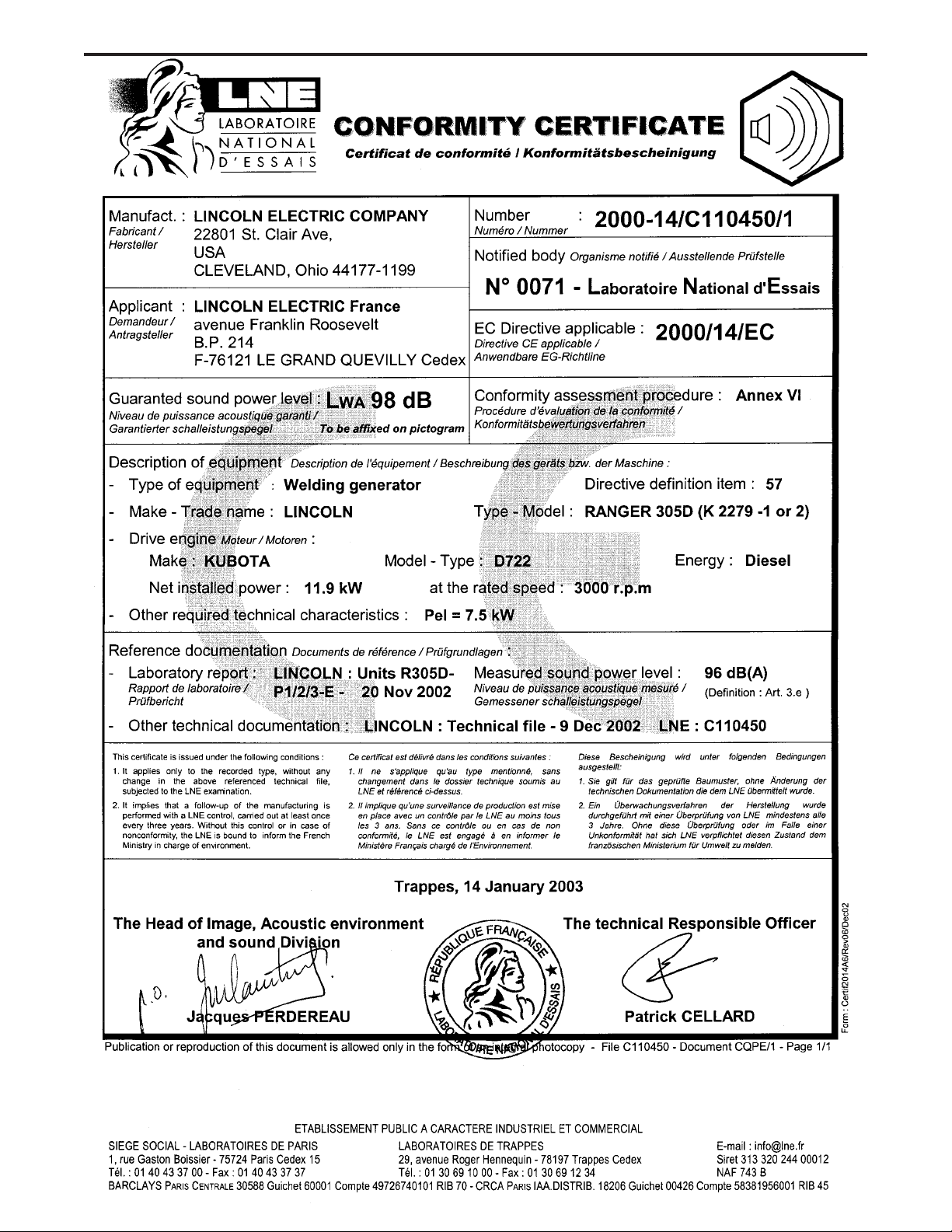
Measured sound power level:
LWA 98 dB (net power Pel = 7.5kW)
LWA 96 dB (net power Pel = 7.5k W)
26 April 2005
Dario Gatti,
SAFETY
vi
RANGER 305D (CE)
Page 8
vii
SAFETY
vii
RANGER 305D (CE)
Page 9
viii
SAFETY
viii
RANGER 305D (CE)
Page 10
for selecting a QUALITY product by Lincoln Electric. We want you
Thank You
to take pride in operating this Lincoln Electric Company product
••• as much pride as we have in bringing this product to you!
Please Examine Carton and Equipment For Damage Immediately
When this equipment is shipped, title passes to the purchaser upon receipt by the carrier. Consequently, Claims
for material damaged in shipment must be made by the purchaser against the transportation company at the
time the shipment is received.
Please record your equipment identification information below for future reference. This information can be
found on your machine nameplate.
Product _________________________________________________________________________________
Model Number ___________________________________________________________________________
Code Number or Date Code_________________________________________________________________
Serial Number____________________________________________________________________________
Date Purchased___________________________________________________________________________
ixix
Where Purchased_________________________________________________________________________
Whenever you request replacement parts or information on this equipment, always supply the information you
have recorded above. The code number is especially important when identifying the correct replacement parts.
On-Line Product Registration
- Register your machine with Lincoln Electric either via fax or over the Internet.
• For faxing: Complete the form on the back of the warranty statement included in the literature packet
accompanying this machine and fax the form per the instructions printed on it.
• For On-Line Registration: Go to our
“Product Registration”. Please complete the form and submit your registration.
Read this Operators Manual completely before attempting to use this equipment. Save this manual and keep it
handy for quick reference. Pay particular attention to the safety instructions we have provided for your protection.
The level of seriousness to be applied to each is explained below:
WEB SITE at www.lincolnelectric.com. Choose “Quick Links” and then
WARNING
This statement appears where the information must be followed exactly to avoid serious personal injury or
loss of life.
CAUTION
This statement appears where the information must be followed to avoid minor personal injury or damage to
this equipment.
Page 11

x
Installation.......................................................................................................................Section A
Technical Specifications.......................................................................................................A-1
Safety Precautions........................................................................................................A-2
Location and Ventilation................................................................................................A-2
Stacking ........................................................................................................................A-2
Angle of Operation ........................................................................................................A-2
Lifting.............................................................................................................................A-2
High Altitude Operation.................................................................................................A-2
High Temperature Operation ........................................................................................A-2
Cold Weather Operation ...............................................................................................A-2
Towing...........................................................................................................................A-3
Vehicle Mounting...........................................................................................................A-3
Pre-Operation Engine Service..............................................................................................A-3
Oil..................................................................................................................................A-3
Fuel ...............................................................................................................................A-3
Engine Coolant..............................................................................................................A-4
Battery Connections......................................................................................................A-4
Muffler Outlet Pipe ........................................................................................................A-4
Spark Arrester...............................................................................................................A-4
Remote Control.............................................................................................................A-4
Electrical Connections..........................................................................................................A-4
Machine Grounding.......................................................................................................A-4
Welding Terminals ........................................................................................................A-5
Welding Output Cables .................................................................................................A-5
Cable Installation...........................................................................................................A-5
Auxiliary Power ....................................................................................................................A-5
Standby Power Connections................................................................................................A-5
Connection of Lincoln Electric Wire Feeders................................................................A-6,A-7
________________________________________________________________________________
TABLE OF CONTENTS
Page
x
Operation.........................................................................................................................Section B
Safety Precautions ..............................................................................................................B-1
General Description..............................................................................................................B-1
For Auxiliary Power ..............................................................................................................B-1
Engine Operation..................................................................................................................B-1
Break in Period.....................................................................................................................B-1
Add Fuel...............................................................................................................................B-1
Fuel ......................................................................................................................................B-1
Welder Controls ............................................................................................................B-2
Engine Controls.............................................................................................................B-3
Starting and Stopping the Engine...........................................................................B-3, B4
Stopping .......................................................................................................................B-4
Welding Operation................................................................................................................B-5
Duty Cycle.....................................................................................................................B-5
Constant Current (Stick) Welding..................................................................................B-5
Downhill Pipe (Stick) Welding .......................................................................................B-5
Tig Welding ...................................................................................................................B-5
Typical Current Ranges for Tungsten Electrodes .........................................................B-5
Wire Welding-CV...........................................................................................................B-6
Arc Gouging ..................................................................................................................B-6
Auxiliary Power .............................................................................................................B-6
________________________________________________________________________________
Accessories.....................................................................................................Section C
Field Installed Options / Accessories ...............................................................................C-1
________________________________________________________________________________
Page 12

xi
TABLE OF CONTENTS
Maintenance......................................................................................................Section D
Safety Precautions ................................................................................................D-1
Routine Maintenance............................................................................................D-1
Engine Maintenance Components ........................................................................D-1
Kubota Diesel Engine............................................................................................D-1
Engine Oil Change..........................................................................................D-2
Engine Oil Refill Capacities.............................................................................D-2
Engine Oil Filter Change.................................................................................D-2
Air Cleaner Service.........................................................................................D-2
Service Instructions And Installation Tips for Engine Air Filter .......................D-3
Cooling System .....................................................................................................D-4
Fan Belt...........................................................................................................D-4
Fuel.................................................................................................................D-4
Bleeding the Fuel System...............................................................................D-4
Fuel Filter........................................................................................................D-5
Engine Adjustment..........................................................................................D-5
Battery Maintenance.......................................................................................D-5
Servicing Optional Spark Arrestor...................................................................D-5
Welder / Generator Maintenance ........................................................................D-6
Storage ...........................................................................................................D-6
Cleaning..........................................................................................................D-6
Brush Removal and Replacement..................................................................D-6
________________________________________________________________________
Troubleshooting..............................................................................................Section E
How to Use Troubleshooting Guide.......................................................................E-1
Troubleshooting Guide.............................................................................E-2 thru E-6
________________________________________________________________________
Diagrams and Dimension Print......................................................................Section F
________________________________________________________________________
Parts List..................................................................................................................P494
________________________________________________________________________
xi
Page 13
A-1
INSTALLATION
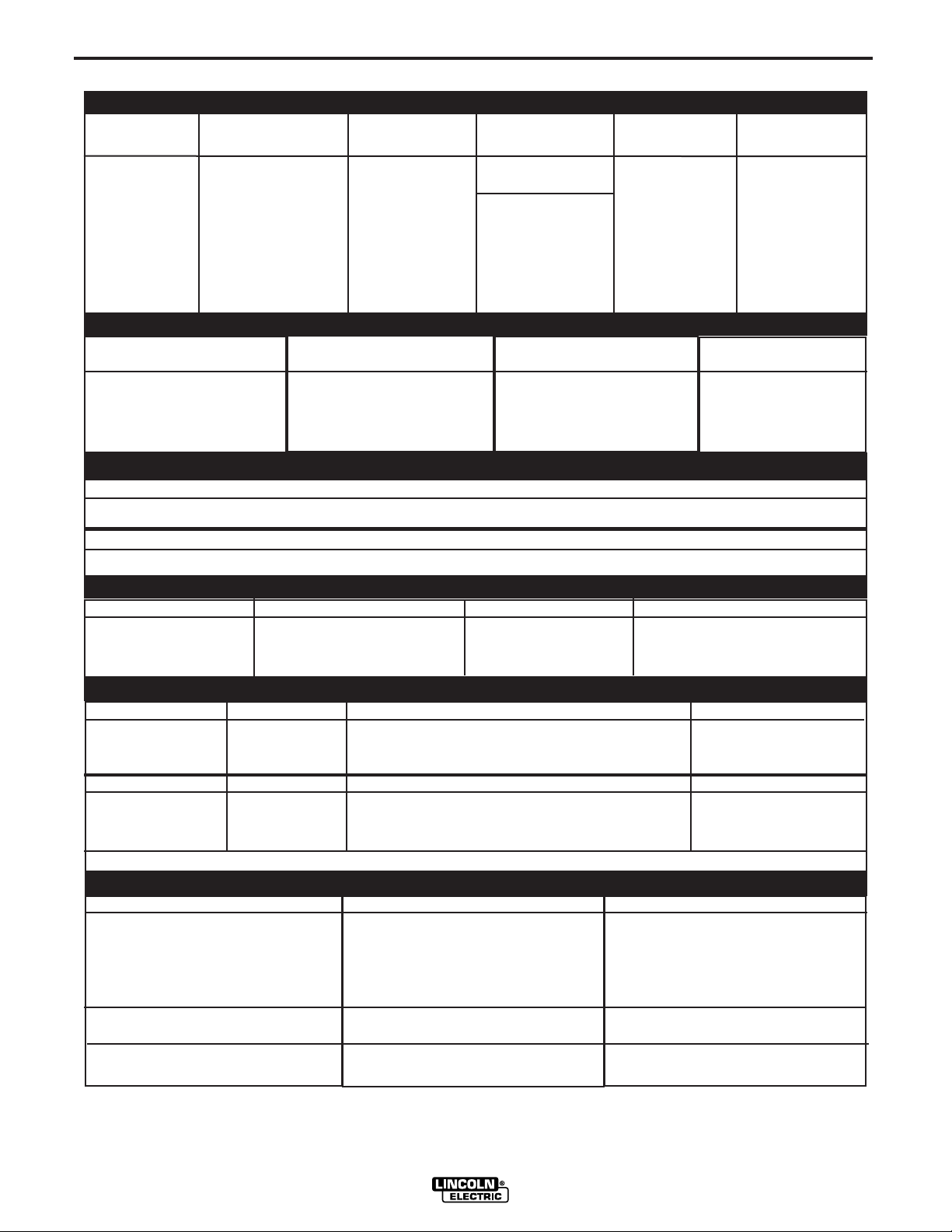
TECHNICAL SPECIFICATIONS - RANGER 305D (CE)
INPUT - DIESEL ENGINE
Make/Model Description Speed (RPM) Displacement Starting Capacities
cu. in. (cu. cm.) System
A-1
3 cylinder, 4 stroke 43.88(789)
12VDC Battery &
15.9 HP starter 45L (12 US.gal.)
(12 KW) High Idle 3100
Kubota
(3)
Net intermittent
D722 3000 RPM Full Load 3000
Bore x Stroke inch (mm)
2.64 x 2.68
(Group 58; 550 Radiator Coolant:
naturally aspirated (67 x 68 mm) cold crank amps) 3.6L(3.85 U Qts)
water cooled Low Idle 2200 Battery Charger
Diesel engine (3.6L)
RATED OUTPUT @ 40° C (104° F) - WELDER
Welding Process
DC Constant Current
DC Pipe Current
Touch-Start™TIG
DC Constant Voltage
Welding Output
Current/Voltage/Duty Cycle
250A / 30V / 100%
250A / 30V / 100%
250A / 20V / 100%
250A / 27V / 100%
Output Range
20 TO 305 AMPS
40 TO 300 AMPS
20 TO 250 AMPS
14 TO 29 VOLTS
RATED OUTPUT @ 40° C (104° F) - GENERATOR
Auxiliary Power
8,500 Watts Peak, / 8,000 Watts Continuous, 50 Hz 230/400 Volts - 3 Phase
Sound Levels
Sound Power: 98 dB Lwa
(1)
PHYSICAL DIMENSIONS
HEIGHT WIDTH DEPTH WEIGHT
909mm 546mm 1524mm
30.0 in.
(2)
21.50 in 60.0 in.
341kg. (752lbs.)
Fuel:
Oil:
3.2L(3.4 US. Qts.)
Max. Weld OCV
@Rated Load RPM
60 Volts
ENGINE
LUBRICATION EMISSIONS FUEL SYSTEM GOVERNOR
Full Pressure Certified to
with Full Flow Filter EPA Tier I Fuel Pump(Codes 11189, 11190), Auto air bleed Mechanical Governor
AIR CLEANER ENGINE IDLER MUFFLER ENGINE PROTECTION
Single Element Automatic Idler Top outlet can be rotated. pressure & engine
ENGINE WARRANTY: 2 year complete (parts and labor) 3rd. year major components (parts and labor)
MODEL NUMBER
Receptacles
Residual Current Device (RCD)
Circuit Breakers (Thermal/Magnetic)
(1) Output rating in watts is equivalent to volt-amperes at unity power factor. Output voltage is within ± 10% at all loads up to rated capacity. When welding,
available auxiliary power will be reduced.
(2) To top of enclosure, add 152mm (6 “) to top of exhaust elbow.
(3) Engine warranty may vary outside of the USA. (See Engine warranty for details)
(4) Center-Tapped to ground.
Electric Fuel Pump(Codes 11122, 11123), Mechanical
system Electric shutoff solenoid Indirect fuel injector.
Low noise Muffler: Shutdown on low oil
Made from long life, aluminized steel. temperature
K2279-1 (UK)
400V (3 Ph) x 1
230V (1 Ph) x 1
115V x 1
(4)
14 Pin Connector
K2279-2 (EUROPE)
400V (3 Ph) x 1
230V (1 Ph) x 2
14 Pin Connector
6 Pin Connector
6 Pin Connector
4-pole, 25 Amp
(30mA trip current)
3 Phase, 20 Amp x 1
1 Phase, 15 Amp x 5
4-pole, 25 Amp
(30mA trip current)
3 Phase, 20 Amp x 1
1 Phase, 15 Amp x 4
RANGER 305D (CE)
(3)
Page 14
A-2
INSTALLATION
A-2
SAFETY PRECAUTIONS
WARNING
Do not attempt to use this equipment until you
have thoroughly read the engine manufacturer’s
manual supplied with your welder. It includes
important safety precautions, detailed engine
starting, operating and maintenance instructions,
and parts lists.
------------------------------------------------------------------------
ELECTRIC SHOCK can kill.
• Do not touch electrically live parts or
electrode with skin or wet clothing.
• Insulate yourself from work and
ground
• Always wear dry insulating gloves.
------------------------------------------------------------------------
ENGINE EXHAUST can kill.
• Use in open, well ventilated areas or
vent exhaust outside.
------------------------------------------------------------------------
MOVING PARTS can injure.
• Do not operate with doors open or
guards off.
• Stop engine before servicing.
• Keep away from moving parts.
------------------------------------------------------------------------
See additional warning information at
front of this operator’s manual.
Only qualified personnel should install,
use, or service this equipment.
LIFTING
The machine weighs approximately 374 kg. (824 lbs)
with a full tank of fuel. A lift bail is mounted to the
machine and should always be used when lifting the
machine.
WARNING
• Lift only with equipment of adequate lifting capacity.
• Be sure machine is stable when lifting.
• Do not lift this machine using lift
bail if it is equipped with a heavy
accessory such as trailer or gas
cylinder.
FALLING • Do not lift machine if lift bail is
EQUIPMENT can damaged.
cause injury. • Do not operate machine while
suspended from lift bail.
--------------------------------------------------------------------------------
HIGH ALTITUDE OPERATION
At higher altitudes, output derating may be necessary. For maximum rating, derate the machine 2.5% to 3.5% for every 305m
(1000ft.). Due to new EPA and other local emissions regulations, modifications to the engine for high altitude are restricted
within the United States and some European Countries. Use
above 1828m (6000 ft.) may be limited due to poor engine performance or excessive exhaust smoke. An authorized Kubota
engine field service shop should be contacted to determine if
any adjustments can be made for operation in higher elevations
locally.
LOCA TION AND VENTILA TION
The welder should be located to provide an unrestricted flow of clean, cool air to the cooling air inlets and to
avoid restricting the cooling air outlets. Also, locate the
welder so that the engine exhaust fumes are properly
vented to an outside area.
STACKING
RANGER 305D (CE) machines cannot be stacked.
ANGLE OF OPERATION
Engines are designed to run in the level condition
which is where the optimum performance is achieved.
The maximum angle of continuous operation is 20
degrees in all directions, 35 degrees Intermittent (less
than 10 minutes continuous) in all directions. If the
engine is to be operated at an angle, provisions must
be made for checking and maintaining the oil level at
the normal (FULL) oil capacity in the crankcase.
When operating the welder at an angle, the effective
fuel capacity will be slightly less than the specified 45
liters (12 gallons).
RANGER 305D (CE)
HIGH TEMPERATURE OPERATION
At temperatures above 40°C,welder output derating is necessary. For maximum output ratings, derate the welder output 2
volts for every 10°C above 40°C.
Cold weather starting:
With a fully charged battery and the proper oil, the
engine should start satisfactorily down to about 15°C
(5°F). If the engine must be frequently started at or
below -5°C (23°F), it may be desirable to install coldstarting aides. The use of No. 1D diesel fuel is recommended in place of No. 2D at temperatures below
-5°C (23°F). Allow the engine to warm up before
applying a load or switching to high idle.
WARNING
Note: Extreme cold weather starting may require
longer glow plug operation.
Under no conditions should ether or other starting
fluids be used!
------------------------------------------------------------------------
Page 15
A-3
INSTALLATION
A-3
TOWING
Check with distributor for the recommended trailer for use with
this equipment for road, in-plant and yard towing by a vehicle. If
the user adapts a non-Lincoln trailer, he must assume responsibility that the method of attachment and usage does not result
in a safety hazard nor damage the welding equipment. Some of
the factors to be considered are as follows:
1. Design capacity of trailer vs. weight of Lincoln equipment and
likely additional attachments.
2. Proper support of, and attachment to, the base of the weld-
ing equipment so there will be no undue stress to the framework.
3. Proper placement of the equipment on the trailer to insure
stability side to side and front to back when being moved
and when standing by itself while being operated or serviced.
4. Typical conditions of use, i.e., travel speed; roughness of surface on which the trailer will be operated; environmental conditions; like maintenance.
5. Conformance with laws in nation / region to be used.
VEHICLE MOUNTING
WARNING
PRE-OPERATION ENGINE SERVICE
READ the engine operating and maintenance instructions supplied with this machine.
• Stop engine and allow to cool before fueling
• Do not smoke when fueling
• Fill fuel tank at a moderate rate and do not overfill.
• Wipe up spilled fuel and allow fumes to clear
before starting engine
• Keep sparks and flame away from tank.
------------------------------------------------------------------------
OIL
The machine is shipped with the engine crankcase
filled with high quality SAE 10W-30 Oil that meets
classification CG-4 or CH-4 for diesel engines. Check
the oil level before starting the engine. If it is not up to
the full mark on the dip stick, add oil as required.
Check the oil level every four hours of running time
during the first 50 running hours. Refer to the engine
Operator’s Manual for specific oil recommendations
and break-in information. The oil change interval is
dependent on the quality of the oil and the operating
environment. Refer to the Engine Operator’s Manual
for more details on the proper service and mainte-
nance intervals.
WARNING
Improperly mounted concentrated loads may
cause unstable vehicle handling and tires or other
components to fail.
• Only transport this Equipment on serviceable
vehicles which are rated and designed for such
loads.
• Distribute, balance and secure loads so vehicle
is stable under conditions of use.
• Do not exceed maximum rated loads for components such as suspension, axles and tires.
• Mount equipment base to metal bed or frame of
vehicle.
• Follow vehicle manufacturer’s instructions.
------------------------------------------------------------------------
FUEL
USE DIESEL FUEL ONLY
WARNING
• Fill the fuel tank with clean, fresh fuel. The
capacity of the tank is, about 45 ltr.’s (12 Gal.’s).
WARNING
NOTE: A fuel shut off valve is located on the pre-
filter/sediment filter. Which should be in
the closed position when the welder is not
operated for extended periods of time.
------------------------------------------------------------------------
RANGER 305D (CE)
Page 16
A-4
INSTALLATION
ENGINE COOLING SYSTEM
WARNING
Air to cool the engine is drawn in the base sides
and exhaust through radiator & case back. It is
important that the intake and exhaust air is not
restricted. Allow a minimum clearance of 0.6m (2
feet) from the case back and 40cm (16”) from
either side of the base to a vertical surface.
------------------------------------------------------------------------
BATTERY CONNECTION
CAUTION
Use caution as the electrolyte is a strong acid that
can burn skin and damage eyes.
------------------------------------------------------------------------
The machine is shipped with the negative battery
cable disconnected. Make certain that the RUN-STOP
switch is in the STOP position. Attach the negative
battery cable to the negative battery terminal and
tighten using a 13mm socket or wrench. It may be
helpful to remove the coolant over-fill bottle. Pull up on
bottle to remove from bracket.
A-4
REMOTE CONTROL
The machine is equipped with a 6-pin and a 14-pin
connector. The 6-pin connector is for connecting the
K857 or K857-1 Remote Control or for TIG welding,
the K870 foot Amptrol or the K963-3 hand Amptrol.
When in the CC-STICK, DOWNHILL PIPE, or CVWIRE modes and when a remote control is connected
to the 6-pin Connector, the auto-sensing circuit automatically switches the OUTPUT control from control at
the welder to remote control.
When in TOUCH START TIG mode and when a
Amptrol is connected to the 6-Pin Connector, the
OUTPUT dial is used to set the maximum current
range of the CURRENT CONTROL of the Amptrol.
The 14-pin connector is used to directly connect a wire
feeder control cable. In the CV-WIRE mode, when the
control cable is connected to the 14-pin connector, the
auto-sensing circuit automatically makes the Output
Control inactive and the wire feeder voltage control
active
WARNING
NOTE: This machine is furnished with a wet charged
battery; if unused for several months, the battery may
require a booster charge. Be careful to charge the battery with the correct polarity.
MUFFLER OUTLET PIPE
Using the clamp provided secure the outlet pipe to the
outlet tube with the pipe positioned such that it will
direct the exhaust to the radiator end of the machine.
Tighten using an adjustable wrench.
SP ARK ARRESTER
Some local laws may require that gasoline or diesel
engines be equipped with exhaust spark arresters
when they are operated in certain locations where
unarrested sparks may present a fire hazard. The
standard muffler included with this welder does not
qualify as a spark arrester. When required by local
regulations, a suitable spark arrester, such as the
K1898-1 must be installed and properly maintained.
WARNING
An incorrect spark arrestor may lead to damage to
the engine or adversely affect performance.
------------------------------------------------------------------------
NOTE: When a wire feeder with a built in welding
voltage control is connected to the 14-pin connector, do not connect anything to the 6-pin connector.
------------------------------------------------------------------------
ELECTRICAL CONNECTIONS
MACHINE GROUNDING
Because this portable engine driven welder creates its
own power, it is not necessary to connect its frame to
an earth ground, unless the machine is connected to
premises wiring (home, shop, etc.)
To prevent dangerous electric shock, other equipment
to which this engine driven welder supplies power
must:
WARNING
• Be grounded to the frame of the welder using a
grounded type plug.
• Be double insulated.
• Do not ground the machine to a pipe that carries
explosive or combustible material.
------------------------------------------------------------------------
RANGER 305D (CE)
Page 17
A-5
When this welder is mounted on a truck or trailer, its
frame must be electrically bonded to the metal frame of
the vehicle. Use a #8 or larger copper wire connected
between the machine grounding stud and the frame of
the vehicle. When this engine driven welder is connected to premises wiring such as that in a home or shop,
its frame must be connected to the system earth
ground. See further connection instructions in the section entitled "Standby Power Connections" .
In general, if the machine is to be grounded, it should
be connected with a #8 or larger copper wire to a solid
earth ground such as a metal water pipe going into the
ground for at least ten feet and having no insulated
joints, or to the metal framework of a building which
has been effectively grounded.
INSTALLATION
A-5
CABLE INSTALLATION
Install the welding cables to your machine as follows:
1. The diesel engine must be OFF to install welding
cables.
2. Remove the flanged nuts from the output terminals.
3. Connect the electrode holder and work cables to
the weld output terminals. The terminals are identified on the case front.
4. Tighten the flanged nuts securely.
5. Be certain that the metal piece you are welding
(the “work”) is properly connected to the work
clamp and cable.
6. Check and tighten the connections periodically.
CAUTION
A machine grounding stud marked with the symbol
is provided on the front of the welder.
WELDING TERMINALS
The machine is equipped with a toggle switch for
selecting "hot" welding terminal when in the "WELD
TERMINALS ON" position or "cold" welding terminal
when in the "REMOTE" position.
WELDING OUTPUT CABLES
With the engine off connect the electrode and work
cables to the output studs. The welding process dictates the polarity of the electrode cable. These connections should be checked periodically and tightened with
a 19mm wrench.
Table A.1 lists recommended cable sizes and lengths
for rated current and duty cycle. Length refers to the
distance from the welder to the work and back to the
welder. Cable diameters are increased for long cable
lengths to reduce voltage drops.
TABLE A-1
TOTAL COMBINED LENGTH OF
ELECTRODE AND WORK CABLES
Cable Length
0-30 meters (0-100Ft.)
30-46 meters (100-150 Ft.)
46-61 meters (150-200 Ft.)
Cable Size for
305 Amps
100% Duty Cycle
1 / 0 AWG
2 / 0 AWG
3 / 0 AWG
• Loose connections will cause the output termi-
nals to overheat. The terminals may eventually
melt.
• Do not cross the welding cables at the output
terminal connection. Keep the cables isolated
and separate from one another.
-----------------------------------------------------------------------
AUXILIARY POWER
The auxiliary power capacity is 8500 watts Peak,
8,000 Watts Continuous of 50 Hz, three phase
power. The auxiliary power capacity rating in watts is
equivalent to volt-amperes at unity power factor. The
max permissible current of the 400 VAC output is 20
amps. Output voltage is within ± 10% at all loads up
to the rated capacity.
STANDBY POWER CONNECTIONS
The machine is suitable for temporary, standby or
emergency power using the engine manufacturer’s
recommended maintenance schedule.
The machine can be permanently installed as a
standby power unit for 400 VAC, three phase, 20
amp service.
Connections must be made by a licensed electrician
who can determine how the power can be adapted to
the particular installation and comply with all applicable electrical codes.
• Take necessary steps to assure load is limited to
the capacity of the RANGER 305D (CE).
• Only a licensed, certified, trained electrician
should install the machine to a premises or residential electrical system. Be certain that:
RANGER 305D (CE)
WARNING
Page 18

A-6
INSTALLATION
A-6
• The installation complies with the National
Electrical Code and all other applicable electrical codes.
• The premises is isolated and no feedback into
the utility system can occur. Certain laws require
the premises to be isolated before the generator
is linked to the premises. Check your local
requirements.
-----------------------------------------------------------------------
CONNECTION OF LINCOLN ELECTRIC
WIRE FEEDERS
Connection of LN-15 to the Ranger 305D
These connections instructions apply to both the LN15 Across The-Arc and Control Cable models. The
LN-15 has an internal contactor and the electrode is
not energized until the gun trigger is closed. When the
gun trigger is closed the wire will begin to feed and the
welding process is started.
• Shut the welder off.
• For electrode Positive, connect the electrode cable
to the "+" terminal of the welder and work cable to
the "-" terminal of the welder. For electrode
Negative, connect the electrode cable "-" terminal
of the welder and work cable to the "+" terminal of
the welder.
• Across The-Arc Model:
WARNING
Connection of the LN-25 to the RANGER 305D
(CE)
Shut off welder before making any electrical connections.
------------------------------------------------------------------------
The LN-25 with or without an internal contactor may
be used with the RANGER 305D (CE). See the appropriate connection diagram in Section F.
NOTE: The LN-25 (K431) Remote Control Module
and (K432) Remote Cable are not recommended for
use with the RANGER 305D (CE).
1. Shut the welder off.
2. For electrode Positive, connect the electrode
cable from the LN-25 to the "+" terminal of the
welder and work cable to the "-" terminal of the
welder. For electrode Negative, connect the electrode cable from the LN-25 to the "-" terminal of
the welder and work cable to the "+" terminal of
the welder.
3. Attach the single lead from the front of the LN-25
to work using the spring clip at the end of the lead.
This is a control lead to supply current to the wire
feeder motor; it does not carry welding current.
Attach the single lead from the front of the LN-15 to
work using the spring clip at the end of the lead. This
is a control lead to supply current to the wire feeder
motor; it does not carry welding current.
Set the "WELD TERMINALS" switch to "WELD TERMINALS ON".
• Control Cable Model:
Connect Control Cable between Engine Welder and
Feeder.
Set the MODE switch to the "CV-WIRE " position.
Set the "WELD TERMINALS" switch to "REMOTELY
CONTROLLED".
Set the "WIRE FEEDER VOLTMETER" switch to
either "+" or "-" as required by the electrode polarity
being used.
Set the "ARC CONTROL" knob to "0" initially and
adjust to suit.
Set the "IDLE" switch to the "AUTO" position. 0
4. Set the MODE switch to the "CV-WIRE " position.
5. Set the "WELD TERMINALS" switch to "WELD
TERMINALS ON"
6. Set the "ARC CONTROL" knob to "0" initially and
adjust to suit.
7. Set the "IDLE" switch to the "AUTO" position.
When not welding, the RANGER 305D (CE)
engine will be at the low idle speed. If you are
using an LN-25 with an internal contactor, the
electrode is not energized until the gun trigger is
closed.
8. When the gun trigger is closed, the current sensing
circuit will cause the RANGER 305D (CE) engine
to go to the high idle speed, the wire will begin to
feed and the welding process started. When welding is stopped, the engine will revert to low idle
speed after approximately 12 seconds unless
welding is resumed.
CAUTION
If you are using an LN-25 without an internal contactor, the electrode will be energized when the
RANGER 305D (CE) is started.
------------------------------------------------------------------------
RANGER 305D
Page 19

A-7
Connection of LN-742 and Cobramatic to RANGER
305D (CE)
• Shut the welder off.
• Connect per instructions on the appropriate connection diagram in Section F.
Connection of PRINCE XL SPOOL GUN to the
RANGER 305D (CE)
Connection of the Prince XL Spool Gun requires the
use of the K1849-1 Adapter Module.
• Shut the Welder off.
• For electrode Positive, connect the electrode cable
to the "+" terminal of the welder and work cable to
the "-" terminal of the welder. For electrode
Negative, connect the electrode cable "-" terminal of
the welder and work cable to the "+" terminal of the
welder.
INSTALLATION
A-7
• Connect the Control Cable of the Spool Gun to the
Adapter Module and connect the Control Cable of
the Adapter Module to the Welder.
• Connect the Gas Hose.
• Set the MODE switch to the "CV-WIRE " position.
• Set the "WELD TERMINALS" switch to "WELD
TERMINALS ON".
• Set the "ARC CONTROL" knob to "0" initially and
adjust to suit.
• Set the “IDLE” switch to the “HIGH” position.
RANGER 305D (CE)
Page 20

B-1
SAFETY PRECAUTIONS
WARNING
OPERATION
• Check radiator for proper coolant level. (Fill if necessary).
• See Engine Owner’s Manual for specific oil and
coolant recommendations.
B-1
Do not attempt to use this equipment until you
have thoroughly read the engine manufacturer’s
manual supplied with your welder. It includes
important safety precautions, detailed engine
starting, operating and maintenance instructions,
and parts lists.
------------------------------------------------------------------------
ELECTRIC SHOCK can kill.
• Do not touch electrically live parts or
electrode with skin or wet clothing.
• Insulate yourself from work and
ground
• Always wear dry insulating gloves.
• Always operate the welder with the hinged door
closed and the side panels in place.
• Read carefully the Safety Precautions page
before operating this machine. Always follow
these and any other safety procedures included
in this manual and in the Engine Instruction
Manual.
GENERAL DESCRIPTION
The RANGER 305D (CE) is a diesel engine powered
DC multi-process welding power source and AC
power generator. The engine drives a generator that
supplies three phase power for the DC welding circuit
and three phase and single phase power for the AC
auxiliary outlets. The DC welding control system uses
state of the art Chopper Technology (CT
rior welding performance.
TM
) for supe-
ADD FUEL
WARNING
• Stop engine while fueling.
• Do not smoke when fueling.
• Keep sparks and flame away
from tank.
• Do not leave unattended while
fueling.
DIESEL FUEL
can cause fire.
• Wipe up spilled fuel and allow
fumes to clear before starting
engine.
• Do not overfill tank, fuel
expansion may cause overflow.
DIESEL FUEL ONLY
------------------------------------------------------------------------
• Remove the fuel tank cap.
• Fill the tank approximately 4 inches (100mm) from
the top of the filler neck to allow for fuel expansion
(observe the fuel gauge while filling). DO NOT FILL
THE TANK TO THE POINT OF OVERFLOW.
• Replace the fuel cap and tighten securely.
• See Engine Owner’s Manual for specific fuel recommendations.
BREAK-IN PERIOD
FOR AUXILIARY POWER:
Start the engine and set the IDLER control switch to
the desired operating mode. Full power is available
regardless of the welding control settings providing no
welding current is being drawn.
ENGINE OPERATION
Before Starting the Engine:
• Be sure the machine is on a level surface.
• Open top & side engine doors and remove the
engine oil dipstick and wipe it with a clean cloth.
Reinsert the dipstick and check the level on the dipstick.
• Add oil (if necessary) to bring the level up to the full
mark. Do not overfill. Close engine door.
RANGER 305D (CE)
Any engine will use a small amount of oil during its
“break-in” period. For the diesel engine on the
RANGER 305D (CE), break-in is about 50 running
hours.
Check the oil every four hours during break-in.
Change the oil after the first 50 hours of operation,
every 100 hours thereafter. Change the oil filter at the
second oil change.
CAUTION
During break-in, subject the RANGER 305D (CE)
to moderate loads. Avoid long periods running at
idle. Before stopping the engine, remove all loads
and allow the engine to cool several minutes.
------------------------------------------------------------------------
Page 21

B-2
OPERATION
B-2
16
1
15
14
2
17
3
13
12
11
4
10
9
8
5
WELDING CONTROLS (Figure B.1)
1. OUTPUT CONTROL:
used to preset the output voltage or current as displayed on the digital meters for the four welding
modes. When in the CC-STICK, DOWNHILL PIPE
or CV-WIRE modes and when a remote control is
connected to the 6-Pin or 14-Pin Connector, the
auto-sensing circuit automatically switches the
OUTPUT CONTROL from control at the welder to
the remote control.
In the CV-WIRE mode, if the wire feeder has voltage control capability, when the control cable is
connected to the 14-Pin Connector, the auto-sensing circuit automatically makes OUTPUT CONTROL inactive and the wire feeder voltage control
active.
When in the TOUCH START TIG mode and when a
Amptrol is connected to the 6-Pin Connector, the
OUTPUT control is used to set the maximum current range of the CURRENT CONTROL of the
Amptrol.
The OUTPUT dial is
FIGURE B.1
2. DIGITAL OUTPUT METERS
3. WELD MODE SELECTOR SWITCH:
7
6
The digital meters allow the output voltage (CVWIRE mode) or current (CC-STICK, PIPE and TIG
modes) to be set prior to welding using the OUTPUT control dial. During welding, the meter display
the actual output voltage (VOLTS) and current
(AMPS). A memory feature holds the display of
both meters on for seven seconds after welding is
stopped. This allows the operator to read the actual current and voltage just prior to when welding
was ceased.
While the display is being held the left-most decimal point in each display will be flashing. The
accuracy of the meters is +/- 3%.
(Provides four selectable welding modes)
CV-WIRE
DOWNHILL PIPE
CC-STICK
TOUCH START TIG
RANGER 305D (CE)
Page 22

B-3
OPERATION
B-3
4. ARC CONTROL: The ARC CONTROL dial is active in
the CV-WIRE, CC-STICK and DOWNHILL PIPE modes,
and has different functions in these modes. This control is
not active in the TIG mode.
CC-STICK mode: In this mode, the ARC CONTROL dial
sets the short circuit current (arc-force) during stick welding
to adjust for a soft or crisp arc. Increasing the dial from –10
(soft) to +10 (crisp) increases the short circuit current and
prevents sticking of the electrode to the plate while welding.
This can also increase spatter. It is recommended that the
ARC CONTROL be set to the minimum number without
electrode sticking. Start with a setting at 0.
DOWNHILL PIPE mode: In this mode, the ARC CONTROL
dial sets the short circuit current (arc-force) during stick
welding to adjust for a soft or a more forceful digging arc
(crisp). Increasing the number from –10 (soft) to +10 (crisp)
increases the short circuit current which results in a more
forceful digging arc. Typically a forceful digging arc is preferred for root and hot passes. A softer arc is preferred for
fill and cap passes where weld puddle control and deposition ("stacking" of iron) are key to fast travel speeds. It is
recommended that the ARC CONTROL be set initially at 0.
CV-WIRE mode: In this mode, turning the ARC CONTROL
clock wise from –10 (soft) to +10 (crisp) changes the arc
from soft and washed-in to crisp and narrow. It acts as an
inductance/pinch control. The proper setting depends on
the procedure and operator preference. Start with a setting
of 0.
10. WIRE FEEDER VOLTMETER SWITCH:
Matches the polarity of the wire feeder voltmeter to the
polarity of the electrode.
ENGINE CONTROLS: (Figure B.2)
11. RUN/STOP SWITCH
engine prior to starting. STOP position stops the engine.
The oil pressure interlock switch prevents battery drain if
the switch is left in the RUN position and the engine is not
operating.
- RUN position energizes the
12. GLOW PLUG PUSH BUTTON -
• When pushed activates the glow plugs as well as
the electric fuel pump for quick starting. Glow plug
should not be activated for more than 20 seconds
continuously.(For Codes 11122, 11123 )
• AUTO BLEED FUNCTION – Air will automatically
bleed from the fuel system by simply pushing the
GLOW PLUG BUTTON. It is generally not required
to crack open fittings in the fuel system to bleed air
from the fuel system.(For Codes 11122, 11123)
• When pushed activates the glow plugs. Glow plug
should not be activated for more than 20 seconds
continuously.(For Codes 11189, 11190)
5. WELD OUTPUT TERMINALS WITH FLANGE
13. START PUSH BUTTON -
NUT: Provides a connection point for the electrode and
work cables.
14. IDLER SWITCH- Has two positions as follows:
6. GROUND STUD:
Provides a connection point for connecting the machine
case to earth ground.
7. 14-PIN CONNECTOR: For attaching wire feeder con-
trol cables to the RANGER 305D (CE). Includes contactor
closure circuit, auto-sensing remote control circuit, and 42V
power. The remote control circuit operates the same as the
6 Pin connector.
Note: The 14-pin connector does not include 120V.
8. 6-PIN CONNECTOR: For attaching optional remote
control equipment. Includes auto-sensing remote control
circuit.
9. WELD TERMINALS SWITCH: In the WELD TERMI-
NALS ON position, the output is electrically hot all the time.
In the REMOTELY CONTROLLED position, the output is
controlled by a wire feeder or amptrol device, and is electri-
cally off until a remote switch is depressed.
Energizes the starter motor to crank engine.
1) In the HIGH position, the engine runs at the high idle
speed controlled by the engine governor.
2) In the AUTO position, the idler operates as follows:
• When switched from HIGH to AUTO or after starting the
engine, the engine will operate at full speed for approximately 12 seconds and then go to low idle speed.
• When the electrode touches the work or power is drawn
for lights or tools (approximately 100 Watts minimum), the
engine accelerates and operates at full speed.
• When welding ceases or the AC power load is turned off,
a fixed time delay of approximately 12 seconds starts. If
the welding or AC power load is not restarted before the
end of the time delay, the idler reduces the engine speed
to low idle speed.
• The engine will automatically return to high idle speed
when there is welding load or AC power
load reapplied.
RANGER 305D (CE)
Page 23

B-4
OPERATION
15. ELECTRIC FUEL GAUGE- Provides accu-
rate, reliable indication of how much fuel is in the
tank
.
16. ENGINE HOUR METER – Displays the total
time that the engine has been running. This meter
is useful for scheduling prescribed maintenance.
B-4
8. The engine will run at high idle speed for approximately 12 seconds and then drop to low idle speed.
Allow the engine to warm up at low idle for several
minutes before applying a load and/or switching to
high idle. Allow a longer warm up time in cold
weather.
NOTE: If the unit fails to start repeat step 4 through
step 7 after waiting 30 seconds
17. ENGINE PROTECTION LIGHT-A warning
indicator light for Low Oil Pressure and/or Coolant
Over Temperature. The light is off when the systems are functioning properly. The light turns on
when the RUN-STOP switch is in the “ON” position prior to starting the engine. If the Engine
Protection or Battery Charging Lights do “not”
turn off shortly after starting the engine shut off
the engine immediately and determine the cause.
STARTING THE ENGINE
1. Remove all plugs connected to the AC power
receptacles.
2. Set IDLER switch to AUTO.
3. Set the RUN/STOP switch to RUN.
4. Press Glow Plug Button and hold 5 to 10 seconds.
5. Press and hold both the “Glow Plug” Button and
START button together until the engine starts or for
up to 10 seconds.
6. Release the engine START button immediately
when the engine starts.
7. Release the glow plug button after the Engine
Protection Light turns off or after an additional 5
seconds maximum.
TABLE B.1
CAUTION
• Do not allow the starter motor to run continuously
for more than 20 seconds.
• Do not push the START button while the engine
is running because this can damage the ring
gear and/or the starter motor.
• IF the Engine Protection or Battery Charging
Lights do “not” turn off shortly after starting the
engine shut off the engine immediately and deter
mine the cause.
-----------------------------------------------------------------------
NOTE: When starting a RANGER 305D (CE) for the
first time, or after and extended period of time of not
operating, it will take longer than normal because the
fuel pump has to fill the fuel system.
STOPPING THE ENGINE
Remove all welding and auxiliary power loads and
allow the engine to run at low idle speed for a few
minutes to cool the engine.
STOP the engine by placing the RUN-STOP switch in
the STOP position.
NOTE: A fuel shut off valve is located on the fuel prefilter. Turn on Fuel shut-off valve on the fuel pre-filter.
TYPICAL RANGER 305D (CE) FUEL CONSUMPTION
Kubota D722 Running time for
Liters/Hr (Gal./Hr) 45 Liters/hours
Low Idle - No Load
2200 R.P.M. .92 (.24) 49.38
High Idle - No Load
3100 R.P.M. 1.62 (.43) 28.07
DC Weld Output
250 Amps @ 30 Volts 3.42 (.90) 13.30
DC Weld Output
225 Amps @ 25 Volts 2.92 (.77) 15.55
8,000 Watts, 3 PHASE 3.35 (.89) 13.54
5,000 Watts, 3 PHASE 2.65 (.70) 17.12
3,000 Watts, 3 PHASE 2.19 (.58) 20.78
RANGER 305D (CE)
Page 24

B-5
OPERATION
WELDER OPERATION
DUTY CYCLE
Duty Cycle is the percentage of time the load is being
applied in a 10 minute period. For example a 60% duty
cycle, represents 6 minutes of load and 4 minutes of no
load in a 10 minute period.
The RANGER 305D (CE) can be used with a broad range
of DC stick electrodes. The MODE switch provides two
stick welding settings as follows:
B-5
The OUTPUT CONTROL dial adjusts the full output range
for stick welding. The ARC CONTROL dial sets the short
circuit current (arc-force) during stick welding to adjust for
a soft or a more forceful digging arc(crisp). Increasing the
number from –10 (soft) to +10 (crisp) increases the short
circuit current which results in a more forceful digging arc.
Typically a forceful digging arc is preferred for root and hot
passes. A softer arc is preferred for fill and cap passes
where weld puddle control and deposition ("stacking" of
iron) are key to fast travel speeds. It is recommended that
the ARC CONTROL be set initially at 0.
CONSTANT CURRENT (CC-STICK) Welding
The CC-STICK position of the MODE switch is designed for
horizontal and vertical-up welding with all types of electrodes, especially low hydrogen.
The OUTPUT CONTROL dial adjusts the full output range
for stick welding.
The ARC CONTROL dial sets the short circuit current (arcforce) during stick welding to adjust for a soft or crisp arc.
Increasing the dial from –10 (soft) to +10 (crisp) increases
the short circuit current and prevents sticking of the electrode to the plate while welding. This can also increase
spatter. It is recommended that the ARC CONTROL be set
to the minimum number without electrode sticking. Start
with a setting at 0.
DOWNHILL PIPE (STICK) Welding
The DOWNHILL PIPE position of the MODE switch is a
TIG WELDING
The TOUCH START TIG setting of the MODE switch is for
DC TIG (Tungsten Inert Gas) welding. To initiate a weld,
the OUTPUT CONTROL dial is first set to the desired current and the tungsten is touched to the work. During the
time the tungsten is touching the work there is very little
voltage or current and, in general, no tungsten contamination. Then, the tungsten is gently lifted off the work in a
rocking motion, which establishes the arc.
To stop the arc, simply lift the TIG torch away from the
work piece. When the arc voltage reaches approximately
30 volts, the arc will go out and the machine will automatically reset to the touch start current level. The tungsten
may then be retouched to the work piece to restrike the
arc. The arc may also be started and stopped with an
Amptrol or Arc Start Switch. See the following paragraphs.
slope controlled setting intended for "out-of-position" and
"down hill" pipe welding where the operator would like to
control the current level by changing the arc length.
TYPICAL CURRENT RANGES
Tungsten Electrode DCEN (-) DCEP (+) Approximate Argon Gas Flow TIG TORCH
Diameter in. (mm) Flow Rate C.F.H. ( l /min.) Nozzle Size (4), (5)
1%, 2% Thoriated 1%, 2% Thoriated Aluminum Stainless Steel
Tungsten Tungsten
.010 (.25) 2-15 (3) 3-8 (2-4) 3-8 (2-4) #4, #5, #6
0.020 (.50) 5-20 (3) 5-10 (3-5) 5-10 (3-5)
0.040 (1.0) 15-80 (3) 5-10 (3-5) 5-10 (3-5)
1/16 (1.6) 70-150 10-20 5-10 (3-5) 9-13 (4-6) #5, #6
3/32 (2.4) 150-250 15-30 13-17 (6-8) 11-15 (5-7) #6, #7, #8
1/8 (3.2) 250-400 25-40 15-23 (7-11) 11-15 (5-7)
5/32 (4.0) 400-500 40-55 21-25 (10-12) 13-17 (6-8) #8, #10
3/16 (4.8) 500-750 55-80 23-27 (11-13) 18-22 (8-10)
1/4 (6.4) 750-1000 80-125 28-32 (13-15) 23-27 (11-13)
TABLE B.2
(1)
FOR TUNGSTEN ELECTRODES
(2)
(1) When used with argon gas. The current ranges shown must be reduced when using argon/helium or pure helium shielding gases.
(2) Tungsten electrodes are classified as follows by the American Welding Society (AWS):
Pure EWP
1% Thoriated EWTh-1
2% Thoriated EWTh-2
Though not yet recognized by the AWS, Ceriated Tungsten is now widely accepted as a substitute for 2% Thoriated Tungsten in AC and DC applications.
(3) DCEP is not commonly used in these sizes.
(4) TIG torch nozzle "sizes" are in multiples of 1/16ths of an inch:
(5) TIG torch nozzles are typically made from alumina ceramic. Special applications may require lava nozzles, which are less prone to breakage, but cannot withstand high temperatures
# 4 = 1/4 in. (6 mm)
# 5 = 5/16 in. (8 mm)
# 6 = 3/8 in. (10 mm)
# 7 = 7/16 in. (11 mm)
# 8 = _ in. (12.5 mm)
#10 = 5/8 in. (16 mm)
and high duty cycles.
RANGER 305D (CE)
Page 25

B-6
When in the TOUCH START TIG mode and when a
Amptrol is connected to the 6-pin Connector the OUTPUT dial is used to set the maximum current range of
the CURRENT CONTROL of the Amptrol.
OPERATION
B-6
For any electrodes the procedures should be kept
within the rating of the machine. For additional electrode information see WWW.Lincolnelectric.com or
the appropriate Lincoln publication.
The ARC CONTROL is not active in the TIG mode.
The RANGER 305D (CE) can be used in a wide variety
of DC TIG welding applications. In general the ‘Touch
Start’ feature allows contamination free starting without
the use of a Hi-frequency unit. If desired, the K930-2
TIG Module can be used with the RANGER 305D (CE).
The settings are for reference.
RANGER 305D (CE) settings when using the K930-2
TIG Module with an Amptrol or Arc Start Switch:
• Set the MODE Switch to the TOUCH START TIG
setting.
• Set the "IDLER" Switch to the "AUTO" position.
• Set the "WELDING TERMINALS" switch to the
"REMOTELY CONTROLLED" position. This will keep
the "Solid State" contactor open and provide a “cold”
electrode until the Amptrol or Arc Start Switch is
pressed
When using the TIG Module, the OUTPUT control on
the RANGER 305D (CE) is used to set the maximum
range of the CURRENT CONTROL on the TIG module
or an Amptrol if connected to the TIG Module. (See
Table B.2.)
WIRE WELDING-CV
Connect a wire feeder to the Ranger 305D according to
the instructions in INSTALLATION INSTRUCTIONS
Section.
ARC GOUGING
The RANGER 305D (CE) can be used for limited arc
gouging. For optimal performance, set the MODE
switch to CC-STICK and the ARC CONTROL to +10.
Set the OUTPUT CONTROL knob to adjust output
current to the desired level for the gouging electrode
being used according to the ratings in the following
TABLE B.3
Carbon Diameter
1/8" 60-90 Amps
5/32" 90-150 Amps
3/16" 200-250 Amps
Current Range (DC, electrode
positive)
Table B.3.
AUXILIARY POWER:
Start the engine and set the IDLER control switch to
the desired operating mode. Full power is available
regardless of the welding control settings providing no
welding current is being drawn.
Simultaneous Welding and Auxiliary Power Loads
The RANGER 305D (CE) in the CV-WIRE mode, permits it to be used with a broad range of flux cored wire
(Innershield and Outershield) electrodes and solid wires
for MIG welding (gas metal arc welding). Welding can
be finely tuned using the ARC CONTROL. Turning the
ARC CONTROL clockwise from –10 (soft) to +10 (crisp)
changes the arc from soft and washed-in to crisp and
narrow. It acts as an inductance/pinch control. The
proper setting depends on the procedure and operator
preference. Start with the dial set at 0.
TABLE A.4
WELDING OUTPUT-
AMPS
0
50
100
150
200
250
PERMISSIBLE POWER-WATTS
(UNITY POWER FACTOR)
8000
6500
5000
3500
2000
RANGER 305D (CE)
While welding, the amount of 3-phase Auxiliary power
available is reduced. (See table A.4)
PERMISSIBLE AUX
POWER @400V, 3PHASE
12 Amps
9 Amps
7 Amps
5 Amps
3 Amps
0
0 Amps
Page 26

C-1
ACCESSORIES
FIELD INSTALLED OPTIONS /
ACCESSORIES
K1898-1 SPARK ARRESTOR - Mounts between muf-
fler & elbow to eliminate any risk of spark from exhaust.
K704 ACCESSORY SET - Includes (10m) 35 ft. of
electrode cable and (9.m) 30 ft. of work cable, headshield, work clamp electrode holder. Cables are rated
at 400 amps, 100% duty cycle.
K857 (7.6m) 25 ft. or K857-1 (30.4m) 100 ft.
REMOTE CONTROL - Portable control provides same
dial range as the output control on the welder. Has a
convenient 6 pin plug for easy connection to the
welder.
C-1
RANGER 305D (CE)
Page 27

D-1
MAINTENANCE
SAFETY PRECAUTIONS
WARNING
• Have qualified personnel do all maintenance
and troubleshooting work.
• Turn the engine off before working inside the
machine or servicing the engine.
• Remove guards only when necessary to
perform maintenance and replace them when
the maintenance requiring their removal is
complete. If guards are missing from the
machine, obtain replacements from a Lincoln
Distributor. (See Operating Manual Parts List.)
• Read the Safety Precautions in the front of this
manual and in the Engine Owner’s Manual before
working on this machine.
D-1
KUBOTA D722 DIESEL ENGINE
FREQUENCY
DAILY OR BEFORE
STARTING ENGINE
Service Intervals
Observe the following for service and maintenance. The lubricating
oil change intervals listed in the table below are for Classes CF,CE
and CD lubricating oils of API classification with a low sulfur fuel in
use. If the CF-4 or CG-4 lubricating oil is used with a high-sulfur
fuel, change the lubricating oil at shorter intervals than recommended in the table below depending on the operating condition.
MAINTENANCE REQUIRED
• FILL FUEL TANK.
• CHECK OIL LEVEL.
• CHECK COOLANT LEVEL.
• CHECK AIR CLEANER ELEMENT AND HOUSING FOR
DIRTY, LOOSE OR DAMAGED
PARTS.
• CHECK AIR INTAKE HOSE
FOR CRACKS OR LOOSE
CONNECTIONS.
• CHECK AIR INTAKE/EXHAUST
AREAS & RADIATOR FOR
DIRT. CLEAN AS NECESSARY.
• CHECK ALTERNATOR BELT
TENSION AND WEAR.
• Keep all equipment safety guards, covers, and
devices in position and in good repair. Keep
hands, hair, clothing, and tools away from the
gears, fans, and all other moving parts when
starting, operating, or repairing the equipment.
Routine Maintenance
At the end of each day’s use, refill the fuel tank to
minimize moisture condensation in the tank. Running
out of fuel tends to draw dirt into the fuel system.
Also, check the crankcase oil level and add oil if
indicated.
ENGINE MAINTENANCE COMPONENTS
KUBOTA D722 DIESEL ENGINE
ITEM
OIL FILTER KUBOTA 70000-15241
AIR FILTER ELEMENT DONALDSON P822686
FUEL FILTER ELEMENT KUBOTA 15231-43560
BATTERY KUBOTA GROUP 58, 550 CCA
BELT KUBOTA 15881-97011
GLOW PLUGS KUBOTA 16851-65512
INLINE FUEL FILTER KUBOTA 12581-43012
MAKE AND PART NUMBER
Intervals
Every 50 hours
Every 75 hours
Every 100 hours
Every 150 hours
Every 200 hours
Every 400 hours
Every 500 hours
Every 1 or 2 months
Every 800 hours
Every 1500 hours
Every 3000 hours
Every 2 years
IMPORTANT
Check of fuel lines and clamp bands.
Change of engine oil
Inspect/Clean air cleaner element
and Vacuator™ valve.
Cleaning of fuel filter.
Check the battery electrolyte level.
Check the fan belt tightness.
Check the radiator and hose clamps.
Replacement of oil filter cartridge
Check the intake air lines.
Replacement of Air Filter element.
Replacement of fuel filter element.
Removal of of sediment in fuel tank.
Cleaning of water jacket (radiator
interior).
Replacement of fan belt.
Recharging of Battery.
Check of valve clearance.
Check the fuel injection nozzle injection pressure.
Check of injection pump.
Check of fuel injector timer.
Replacement of battery
Replacement of radiator hoses and
clamp band.
Replacement of fuel pipes and
clamps.
Change the radiator coolant.(L.L.C.)
Replacement of intake air line.
Items
•
*1
•
*1,*2
*3
*3
*3
*3
*4
•These jobs should be done after the first 50 hours of operation.
*1 Air cleaner should be inspected/cleaned more often in dusty conditions than
the normal conditions.
*2 Follow Service Instructions and Installation Tips for air cleaner in
Section D.
*3 Consult your local KUBOTA Dealer for this service.
*4 Replace only if necessary.
Please see Engine Owners Manual for Warranty Statement in detail.
RANGER 305D (CE)
Page 28

D-2
MAINTENANCE
D-2
ENGINE OIL CHANGE
Drain the engine oil while the engine is warm to
assure rapid and complete draining. It is recommended that each time the oil is changed the oil filter be
changed as well.
• Be sure the unit is off. Disconnect the negative battery cable to ensure safety.
• Locate oil drain hose and valve in bottom of base
and pull through the hole in the battery access panel
on the welder.
• Remove the cap from the drain valve. Push valve in
and twist counterclockwise. Pull to open and drain
the oil into a suitable container for disposal.
• Close the drain valve by pushing in and twisting
clockwise. Replace the cap.
• Re-fill the crankcase to the upper limit mark on the
dipstick with the recommended oil (see engine operation manual OR engine service items decal OR
below). Replace and tighten the oil filler cap securely.
• Push oil drain hose and valve back into unit, re-connect negative battery cable, and close doors and
engine top cover before restarting unit.Wash your
hands with soap and water after handling used
motor oil. Please dispose of used motor oil in a
manner that is compatible with the environment.
We suggest you take it in a sealed container to your
local service station or recycling center for reclamation. DO NOT throw it in the trash; pour it on the
ground or down a drain.
ENGINE OIL REFILL CAPACITIES
Without oil filter replacement:
• 3.2 liter (3.3 U.S. Quart)
With oil filter replacement:
• 3.2 liter ( 3.4 U.S. Quart.)
Use motor oil designed for diesel engines that meets
requirements for API service classification
CC/CD/CE/CF/CF-4/CG-4 or CH-4.
ACEA E1/E2/E3. Always check the API service label
on the oil container to be sure it includes the letters
indicated. (Note: An S-grade oil must not be used in a
diesel engine or damage may result. It IS permissible
to use an oil that meets S and C grade service classifications.)
SAE 10W30 is recommended for general, all temperature use, -15C to 40C (5F to 104F).
See engine owner’s manual for more specific information on oil viscosity recommendations.
OIL FILTER CHANGE
• Drain the oil.
• Remove the oil filter with an oil filter wrench and
drain the oil into a suitable container. Discard the
used filter. Note: Care should be taken during filter
removal to not disrupt or damage in any way the fuel
lines.
• Clean the filter mounting base and coat the gasket
of the new filter with clean engine oil.
• Screw the new filter on by hand until the gasket con-
tacts the mounting base. Using an oil filter wrench,
tighten the filter an additional 1/2 to 7/8 of a turn.
• Refill the crankcase with the specified amount of the
recommended engine oil. Reinstall the oil filler cap
and tighten securely.
• Start the engine and check for oil filter leaks.
• Stop the engine and check the oil level. If neces-
sary, add oil to the upper limit mark on the dipstick.
WARNING
• Never use gasoline or low flash point solvents
for cleaning the air cleaner element. A fire or
explosion could result.
CAUTION
• Never run the engine without the air cleaner.
Rapid engine wear will result from contaminants,
such as dust and dirt being drawn into the
engine.
------------------------------------------------------------------------
AIR CLEANER
The diesel engine is equipped with a dry type air filter.
Never apply oil to it. Service the air cleaner as follows:
Replace the element at least every 200 hours of
operation and sooner under dusty conditions.
RANGER 305D (CE)
Page 29

D-3
Service Instructions & Installation Tips
For Engine Air Filter
Release the
1
Seal Carefully
Unlatch and remove the service
cover of the air cleaner. Make
certain the latches are folded
back against the cover so that
they donít hinder filter
removal/installation. Most latches
are spring loaded to fold back when open.
The filter fits tightly over the outlet tube,
creating the critical seal on the inside
diameter of the filter endcap. The filter
should be removed gently to reduce the
amount of dust dislodged. There will be
some initial resistance, similar to breaking
the seal on a jar.
Gently move the end of the
filter back and forth to break the seal.
Avoid Dislodging
2
Dust from the Filter
Gently pull the
filter off the outlet
tube and out of the
housing. Avoid
knocking the filter
against the housing.
Clean Sealing Surface
3
of the Outlet Tube
Use a clean cloth to wipe the sealing
surface. Dust on the outside diameter of the
outlet tube could hinder
an effective seal
and cause leakage.
Make sure that all
contaminant is
removed before the
new filter is inserted.
Insert the New
7
RadialSealô Filter
by Hand
Insert carefully. Seat the new filter by hand,
making certain it is completely into the air
cleaner housing
before latching the cover in
place. If the cover hits the filter before it is
fully in place, remove the cover and push
(by hand) the
filter further into
the air cleaner
and try again.
The cover
should go on
with no extra force.
Never use the latches on the cover to force
the filter into the air cleaner! It is tempting
to assume the cover will do the job of
seating the filter ñ but it will not! Using the
latches to push the filter in could cause
damage to the housing and will void the
warranty.
Donaldson filters with RadialSeal
™
Sealing
Technology are self-aligning, self-centering,
and self-sealing. A new filter has a dry
lubricant to aid installation. The critical
sealing area will stretch slightly, adjust
itself and distribute the sealing pressure
evenly. To complete a tight seal, apply
pressure by hand at the outer rim of the
filter, not the flexible center. (Avoid
pushing on the center of the urethane end
cap.) No cover pressure is required to hold
the seal. Again, do NOT use the service
cover to push the filter into place!
When the filter in is place, put the service
cover back on, making sure the Vacuator
™
Valve points down. Inspect the Vacuator
Valve for cracks or dust hang-ups to insure
that it is functioning properly. Re-fasten
the latches.
Check Connections
8
for Tight Fit
Make sure that all clamps, bolts, and
connections in the entire air intake system
are tight. Check for holes in piping, and
repair if needed.
Clean the Inside of
4
the Outlet Tube
Carefully wipe the inside
of the outlet tube
with a clean cloth.
Dirt accidently
transferred to the
inside of the outlet
tube will reach the
engine and cause wear.
(Engine manufacturers says that it takes
only a few grams of dirt to ëdustí an
engine!) Be careful not to damage the
sealing area on the tube.
Check the Old
5
Filter for Leak Clues
Visually inspect the old filter for any signs
of leaks. A streak of dust on
the clean side of the filter
is a telltale sign.
Remove any cause
of leaks before
installing new
filter.
Inspect the New
6
Filter for Damage
Inspect the new filter carefully,
paying attention to the inside of
the open end,
which is the
sealing area.
NEVER install
a damaged filter.
™
MAINTENANCE
D-3
RANGER 305D (CE)
Page 30

D-4
COOLING SYSTEM
MAINTENANCE
FUEL
D-4
WARNING
HOT COOLANT
• Do not remove cap if radiator is
hot.
------------------------------------------------------------------------
Check the coolant level by observing the level in the
radiator and recovery bottle. Add 50/50 antifreeze /
water solution if the level is close to or below the
"LOW" mark. do not fill above the "FULL" mark.
Remove radiator cap and add coolant to radiator. Fill
up to the top of the tube in the radiator filler neck
which includes a connecting hose coming from the
thermostat housing.
To drain the coolant, open the valve of the radiator.
Open the radiator cap to allow complete drainage.
(Tighten the valve and refill with a 50/50
antifreeze/water solution.) Use an automotive grade
(low silicate) ethylene glycol antifreeze. The cooling
system capacity is 3.6L (3.85 quarts). Squeeze
upper and lower radiator hoses while filling to bleed air
from system coolant. Replace and tighten the radiator
cap.
can burn skin.
CAUTION
Always premix the antifreeze and clean tap water
before adding to the radiator. It is very important
that a precise 50/50 solution be used with this
engine year round. This gives proper cooling during hot weather and freezing protection to -37° C
(-34° F).
At the end of each day’s use, refill the fuel tank to minimize moisture condensation and dirt contamination in
the fuel line. Do not overfill; leave room for the fuel to
expand.
Use only fresh, No. 2 grade DIESEL fuel. Do not use
kerosene.
See the Engine Operator's Manual for instructions on
replacing the fuel filter.
BLEEDING THE FUEL SYSTEM
You may need to bleed air from the fuel system if the
fuel filter or fuel lines have been detached, the fuel
tank has been ran empty or after periods of long storage. It is recommended that the fuel shutoff valve be
closed during periods of non-use.
(For Codes 11122, 11123)
The Kubota D722 engine supplied with this welder is
equipped with an automatic bleeding mechanism that
functions when the electric fuel pump is actuated. It is
generally not necessary to open a vent screw or fuel
line fitting to bleed the fuel system.
(For Codes 11189, 11190)
The Kubota D722 engine supplied with this welder is
equipped with an automatic bleeding mechanism that
helps purge the air from the mechanical fuel pump
system. It is generally not necessary to open a vent
screw or fuel line fitting to bleed the fuel system.
Operate the priming lever on the pump to assist starting after extended periods of non-use or out of fuel
conditions.
WARNING
Cooling solution exceeding 50% ethylene glycol
can result in engine overheating and damage to
the engine. Coolant solution must be premixed
before adding to radiator.
------------------------------------------------------------------------
Periodically remove the dirt from the radiator fins.
Periodically check the fan belt and radiator hoses.
Replace if signs of deterioration are found.
TIGHTENING THE FAN BELT
If the fan belt is loose, the engine can overheat and
the battery lose its charge. Check tightness by pressing on the belt midway between the pulleys. It should
deflect about 6mm (.25 in) under a load of 9 Kg (20
lbs).
RANGER 305D (CE)
To avoid personal injury, do not bleed a hot
engine. This could cause fuel to spill onto a hot
exhaust manifold, creating a danger of fire.
-----------------------------------------------------------------------Bleed the fuel system as follows:
1. Fill the fuel tank with fuel.
2. Open the fuel shut off valve (vertical position of
handle) on the Fuel Filter.
3. Press and hold the glow plug button for 10 to 20
seconds.(For Codes 11122, 11123)
3a. Crank the engine by pressing the start button for
45 seconds. (For Codes 11189, 11190)
4. Check to see that fuel is flowing through both fuel
filters.
5. Follow the normal STARTING procedures.
Page 31

D-5
MAINTENANCE
D-5
FUEL FILTER
1. Check the fuel filter and fuel pre-filter for water
accumulation or sediment.
2. Replace the fuel filter if it is found with excessive
water accumulation or sediment. Empty fuel pre-fil-
ter.
OVERSPEED IS HAZARDOUS
The maximum allowable high idle speed for this
machine is 3150 RPM, no load. Do NOT tamper
with governor components or setting or make any
other adjustments to increase the maximum
speed. Severe personal injury and damage to the
machine can result if operated at speeds above
maximum.
ENGINE ADJUSTMENT
Adjustments to the engine are to be made only by a
Lincoln Service Center or an authorized Field Service
Shop.
BATTERY MAINTENANCE
To access the battery, Disconnect the Negative and
then Positive battery cables. Remove the 4 screws
from the battery door using a screwdriver or a 10mm
socket. Remove the 2 nuts from the battery bracket
using a 11mm wrench or socket. Slide the battery out
and remove from welder
WARNING
GASES FROM BATTERY can explode.
● Keep sparks, flame and cigarettes
away from battery.
To prevent EXPLOSION when:
● INSTALLING A NEW BATTERY — disconnect
negative cable from old battery first and connect to new battery last.
● CONNECTING A BATTERY CHARGER —
remove battery from welder by disconnecting
negative cable first, then positive cable and
battery clamp. When reinstalling, connect
negative cable last. Keep well ventilated.
● USING A BOOSTER — connect positive lead to
battery first then connect negative lead to neg-
ative battery lead at engine foot.
BATTERY ACID can burn eyes and
skin.
● Wear gloves and eye protection
and be careful when working near
battery.
● Follow instructions printed on battery.
CLEANING THE BATTERY
Keep the battery clean by wiping it with a damp cloth
when dirty. If the terminals appear corroded, disconnect the battery cables and wash the terminals with an
ammonia solution or a solution of 113g (1/4 pound) of
baking soda and 0.9461L (1 quart) of water. Be sure
the battery vent plugs (if equipped) are tight so that
none of the solution enters the cells.
After cleaning, flush the outside of the battery, the battery compartment, and surrounding areas with clear
water. Coat the battery terminals lightly with petroleum
jelly or a non-conductive grease to retard corrosion.
Keep the battery clean and dry. Moisture accumulation on the battery can lead to more rapid discharge
and early battery failure.
CHECKING THE ELECTROLYTE LEVEL
If battery cells are low, fill them to the neck of the filler
hole with distilled water and recharge. If one cell is
low, check for leaks.
CHARGING THE BATTERY
When you charge, jump, replace, or otherwise connect battery cables to the battery, be sure the polarity
is correct. Improper polarity can damage the charging
circuit. The RANGER 305D (CE) positive (+) battery
terminal has a red terminal cover.
If you need to charge the battery with an external
charger, disconnect the negative cable first, then the
positive cable before you attach the charger leads.
After the battery is charged, reconnect the positive
battery cable first and the negative cable last. Failure
to do so can result in damage to the internal charger
components.
Follow the instructions of the battery charger manufacturer for proper charger settings and charging time.
SERVICING OPTIONAL SPARK
ARRESTOR
Clean every 100 hours.
WARNING
• MUFFLER MAY BE HOT
• ALLOW ENGINE TO COOL BEFORE INSTALLING
THE SPARK ARRESTER!
• DO NOT OPERATE ENGINE WHILE INSTALLING
THE SPARK ARRESTER!
RANGER 305D (CE)
Page 32

D-6
MAINTENANCE
WELDER / GENERATOR
MAINTENANCE
STORAGE: Store the RANGER 305D (CE) in clean,
dry protected areas.
CLEANING: Blow out the generator and controls periodically with low pressure air. Do this at least once a
week in particularly dirty areas.
BRUSH REMOVAL AND REPLACEMENT: It’s nor-
mal for the brushes and slip rings to wear and darken
slightly. Inspect the brushes when a generator overhaul is necessary.
CAUTION
• Do not attempt to polish slip rings while the
engine is running.
D-6
WARNING
• Service and Repair should only be performed by
Lincoln Electric Factory Trained Personnel.
Unauthorized repairs performed on this equipment may result in danger to the technician and
machine operator and will invalidate your factory
warranty. For your safety and to avoid Electrical
Shock, please observe all safety notes and precautions.
RANGER 305D (CE)
Page 33

E-1
TROUBLESHOOTING
HOW TO USE TROUBLESHOOTING GUIDE
WARNING
Service and Repair should only be performed by Lincoln Electric Factory Trained Personnel.
Unauthorized repairs performed on this equipment may result in danger to the technician and
machine operator and will invalidate your factory warranty. For your safety and to avoid Electrical
Shock, please observe all safety notes and precautions detailed throughout this manual.
__________________________________________________________________________
E-1
This Troubleshooting Guide is provided to help you
locate and repair possible machine malfunctions.
Simply follow the three-step procedure listed below.
Step 1. LOCATE PROBLEM (SYMPTOM).
Look under the column labeled “PROBLEM (SYMPTOMS)”. This column describes possible symptoms
that the machine may exhibit. Find the listing that
best describes the symptom that the machine is
exhibiting.
Step 2. POSSIBLE CAUSE.
The second column labeled “POSSIBLE CAUSE” lists
the obvious external possibilities that may contribute
to the machine symptom.
Step 3. RECOMMENDED COURSE OF ACTION
This column provides a course of action for the
Possible Cause, generally it states to contact your
local Lincoln Authorized Field Service Facility.
If you do not understand or are unable to perform the
Recommended Course of Action safely, contact your
local Lincoln Authorized Field Service Facility.
CAUTION
If for any reason you do not understand the test procedures or are unable to perform the tests/repairs safely, contact your
Local Lincoln Authorized Field Service Facility for technical troubleshooting assistance before you proceed.
RANGER 305D (CE)
Page 34

E-2
Observe all Safety Guidelines detailed throughout this manual
PROBLEMS
(SYMPTOMS)
TROUBLESHOOTING
POSSIBLE
CAUSE
E-2
RECOMMENDED
COURSE OF ACTION
Major Physical or Electrical Damage
is Evident.
Engine will not "crank".
Engine will "crank" but not start.
1. Contact your local Lincoln
Authorized Field Service
Facility.
1. Battery is low,
2. Loose battery cable connections.
Inspect, clean and tighten terminals.
3. Faulty engine starter motor.
Contact authorized local Engine
Service Shop.
1. Fuel shut off valve on Main Fuel
Filter in the OFF position. Open
valve (vertical) position of handle.
2. Fuel Filters dirty/clogged. Check
and replace main filter element
and/or Inline Fuel Filter.
3. Out of fuel. Fill tank and bleed fuel
system.
4. High coolant temperature or low
oil pressure. (indictor lights lit)
Check oil and coolant levels. Fill if
required. Check for loose or broken fan belt.
5. Faulty fuel shutdown solenoid.
Check that shutdown solenoid is
functioning properly and not binding/ contact authorized engine
service shop.
6. Faulty fuel pump. Check for fuel
flow through filters. Contact
authorized local Engine Service
Shop.
Charge Battery.
I
f all recommended possible areas
of misadjustment have been
checked and the problem persists,
Contact your local Lincoln
Authorized Field Service Facility.
Engine shuts down shortly after
starting.
1. High coolant temperature or low
oil pressure. (indictor light lit)
Change oil and oil filters and fill to
proper level. Check and fill coolant
level. Check for loose or broken
fan belt. Start engine and look for
leaks.
2. Faulty oil pressure switch or other
engine component. Contact
authorized local Engine Service
Shop.
3. Faulty engine protection relay.
CAUTION
If for any reason you do not understand the test procedures or are unable to perform the tests/repairs safely, contact your
Local Lincoln Authorized Field Service Facility for technical troubleshooting assistance before you proceed.
RANGER 305D (CE)
Page 35

E-3
Observe all Safety Guidelines detailed throughout this manual
PROBLEMS
(SYMPTOMS)
TROUBLESHOOTING
POSSIBLE
CAUSE
E-3
RECOMMENDED
COURSE OF ACTION
Engine shuts down while under a
load.
Engine runs rough.
Battery does not stay charged.
Engine will not idle down to low
speed.
1. High radiator coolant temperature. Reduce load if it is exceeding machine rating. Add coolant
to system if low. Clean fins on
radiator if dirty. Tighten fan belt if
loose. Remove objects blocking
or close to intake openings on
both sides of base and exhaust
end (case back).
1. Dirty fuel or air filters. Inspect and
clean/replace filters as needed.
Inspect and clean/replace filters
as needed.
2. Water in fuel. If water found in
tank. Empty fuel tank and refill
then purge fuel lines.
1. Faulty battery. Replace.
2. Loose connections at battery or
alternator. Clean and tighten connections.
3. Faulty engine alternator or charger module. Consult authorized
Engine Service Shop.
1. Idler switch in High idle position.
Set switch to Auto.
2. External load on welder or auxiliary power.
loads.
3. Faulty PC board or idler solenoid.
Remove all external
If all recommended possible areas of
misadjustment have been checked
and the problem persists, Contact
your local Lincoln Authorized
Field Service Facility.
Engine will not go to high idle when
attempting to weld.
1. Poor work lead connection to
work. Make sure work clamp is
tightly
metal.
2. "Contactor" switch is in wrong
position.
welding without a control cable.
Refer to Operations chapter for proper use of this switch.
3. Faulty PC board. Low idle speed
set to low.
connected to clean base
Set to "Welding On" when
CAUTION
If for any reason you do not understand the test procedures or are unable to perform the tests/repairs safely, contact your
Local Lincoln Authorized Field Service Facility for technical troubleshooting assistance before you proceed.
RANGER 305D (CE)
Page 36

E-4
Observe all Safety Guidelines detailed throughout this manual
PROBLEMS
(SYMPTOMS)
TROUBLESHOOTING
POSSIBLE
CAUSE
E-4
RECOMMENDED
COURSE OF ACTION
Engine will not go to high idle when
using auxiliary power.
Engine will not go to high idle
under weld or auxiliary loading.
Engine does not develop full
power. Engine runs rough.
Engine will not go to high idle when
attempting to weld or using auxiliary power. Switching to manual
high idle does not work.
Engine will not shut off.
1. Auxiliary power load is less than
100 watts.
with less than a 100 watt load. Set
idler to "High".
2. Faulty PC board.
1. Faulty idler solenoid. Check for
bent linkage or broken spring
1. Fuel filter clogged,
2. Air filter clogged,
3. High idle setting incorrect, check
and adjust if required.
4. Valves out of adjustment.
5. Fuel contaminated with water or
sediment. Check fuel pre-filter
and empty of water, bleed fuel
system. Replace fuel in tank if
needed.
1. Broken spring on Idle Solenoid,
solenoid linkage binding, Faulty
PC board, low idle speed set too
low on idle solenoid.
1. Fuel Shutdown solenoid not
functioning properly / linkage
binding. Stop engine by shutting
off valve located on main fuel filter. Contact authorized local
Engine Service Shop.
Idler may not respond
Replace.
clean or replace.
I
f all recommended possible areas
of misadjustment have been
checked and the problem persists,
Contact your local Lincoln
Authorized Field Service Facility.
Engine does not develop full power.
Low weld and auxiliary output.
Engine runs rough.
1. Fuel filter dirty/clogged. Replace.
2. Air filter dirty/clogged. Replace
Air Filter Element.
3. Fouled fuel injector(s). Contact
authorized Engine Service Shop.
4. Fuel contaminated with water.
Check Main Filter Bowl and Inline
Fuel filters for water. Clean and
replace as needed. Replace fuel
in tank.
5. Cracked or loose fuel hose.
Replace hose and tighten
clamps.
6. Valves out of adjustment. Contact
authorized local Engine Service
Shop.
CAUTION
If for any reason you do not understand the test procedures or are unable to perform the tests/repairs safely, contact your
Local Lincoln Authorized Field Service Facility for technical troubleshooting assistance before you proceed.
RANGER 305D (CE)
Page 37
E-5
Observe all Safety Guidelines detailed throughout this manual
PROBLEMS
(SYMPTOMS)
TROUBLESHOOTING
POSSIBLE
CAUSE
E-5
RECOMMENDED
COURSE OF ACTION
No welding power output.
Auxiliary Power OK.
Welder has output but no control.
Wire feeder does not work when
control cable is connected to 14 pin
connector.
1. Poor work lead connection to
work. Make sure work clamp is
tightly connected to clean base
metal.
2. "Weld Terminals" switch in wrong
position. Place switch in "Weld
Terminals On" position when
welding without control cable.
3. Faulty PC board.
1. Poor remote/control cable connection to 6-pin or 14-pin connector.
Check connections.
2. Faulty remote cable or faulty wire
feeder or wire feeder cable.
Replace if necessary.
3. Faulty control potentiometer or PC
board.
1. Wire Feeder Power circuit breaker
open. Check 42V beaker and
reset if tripped.
2. Faulty control cable. Repair or
replace cable.
3. Faulty wire feeder. Replace wire
feeder.
I
f all recommended possible areas
of misadjustment have been
checked and the problem persists,
Contact your local Lincoln
Authorized Field Service Facility.
No auxiliary power.
1. Open circuit breakers. Reset
breakers. If breakers keep tripping, reduce power draw.
2. Faulty connections to auxiliary
receptacles. Check connections.
3. RCD tripped. Clear any ground
fault and reset RCD circuit by
pressing "Reset" button.
4. Faulty PC board or welder alternator.
CAUTION
If for any reason you do not understand the test procedures or are unable to perform the tests/repairs safely, contact your
Local Lincoln Authorized Field Service Facility for technical troubleshooting assistance before you proceed.
RANGER 305D (CE)
Page 38

E-6
Observe all Safety Guidelines detailed throughout this manual
PROBLEMS
(SYMPTOMS)
TROUBLESHOOTING
POSSIBLE
CAUSE
E-6
RECOMMENDED
COURSE OF ACTION
The welding arc is “cold.” The welding arc is not stable or is not satisfactory. the engine runs normally.
The auxiliary power is normal.
1. Make sure the MODE selector
switch is in the correct position for
the process being used. (For example, CV-WIRE, PIPE, CC-STICK.)
2. Make sure the electrode (wire, gas,
voltage, current etc.) is correct for
the process being used.
3. Check for loose or faulty connections at the weld output terminals
and welding cable connections.
4. The welding cables may be too long
or coiled, causing an excessive
voltage drop.
If all recommended possible areas of
misadjustment have been checked
and the problem persists, Contact
your local Lincoln Authorized
Field Service Facility.
CAUTION
If for any reason you do not understand the test procedures or are unable to perform the tests/repairs safely, contact your
Local Lincoln Authorized Field Service Facility for technical troubleshooting assistance before you proceed.
RANGER 305D (CE)
Page 39

F-1
DIAGRAMS
F-1
RANGER 305D (CE)
Page 40

F-2
DIAGRAMS
F-2
RANGER 305D (CE)
Page 41

F-3
DIAGRAMS
or service this equipment.
Only qualified personnel should install,use
Keep away from moving parts.
Keep guards in place.
MOVING PARTS can injure
F-3
A.01
S24787-13
TO WORK
ENGINE WELDERS /LN-742 CONNECTION DIAGRAM
WARNING
Do not operate with panels open.
before servicing.
Disconnect NEGATIVE (-) Battery lead
ELECTRIC SHOCK can kill
Do not touch electrically live parts.
CABLE PLUG
TO LN-742 INPUT
K1819-10 CONTROL CABLE
ELECTRODE CABLE
TO WIRE FEED UNIT
_
+
CAUTION:
ANY INCREASE OF THE HIGH IDLE ENGINE RPM BY CHANGING THE GOVERNOR SETTING OR OVERRIDING THE THROTTLE LINKAGE WILL CAUSE
AN INCREASE IN THE AC WIRE FEEDER VOLTAGE, WHICH CAN DAMAGE THE CONTROL CIRCUIT. THE ENGINE GOVERNOR SETTING IS PRE-SET
AT THE FACTORY – DO NOT ADJUST ABOVE RPM SPECIFICATIONS LISTED IN THE ENGINE WELDER OPERATING MANUAL.
N.A. WELDING CABLES MUST BE OF PROPER CAPACITY FOR THE CURRENT AND DUTY CYCLE OF IMMEDIATE AND FUTURE
APPLICATIONS. SEE OPERATING MANUAL.
N.B. CONNECT WELDING CABLES TO OUTPUT STUDS FOR DESIRED POLARITY. POSITION THE WIRE FEEDER VOLTMETER SWITCH TO
MATCH THE POLARITY OF THE ELECTRODE CABLE.
N.C. PLACE THE MODE SWITCH IN THE “CV-WIRE” POSITION.
N.D. PLACE WELDER TERMINALS SWITCH TO “REMOTELY CONTROLLED” POSITION.
14 PIN
AMPHENOL
N.E. PLACE IDLER SWITCH IN “AUTO” OR “HIGH” IDLE POSITION AS DESIRED.
RANGER 305D (CE)
Page 42

F-4
2
9/03
DIAGRAMS
F-4
RANGER 305D (CE)
Page 43

F-5
DIAGRAMS
F-5
RANGER 305D (CE)
Page 44

F-6
Enhanced Diagram
DIAGRAMS
F-6
RANGER 305D (CE)
NOTE: This diagram is for reference only. It may not be accurate for all machines covered by this manual. The specific diagram for a particular code is pasted inside
the machine on one of the enclosure panels. If the diagram is illegible, write to the Service Department for a replacement. Give the equipment code number.
Page 45

F-7
Enhanced Diagram
Twisted
RANGER 305D CE KUBOTA WIRING DIAGRAM - UK (FOR CODE 11189)
261
DIAGRAMS
A
Meter
VOLTS
WELD
WINDINGS
W5
C11
301
C10
HEATSINK
302
P4 - J4
10
10
5
5
5
5
5
5
M4
M4
M4
M4
M4
M4
M2
M2
M2
M2
M2
M2
M3
M3
M3
M3
M3
M3
M5
M5
M5
M5
M5
M5
M10
M10
M10
M10
M10
M10
M9
M9
M9
M9
M9
M9
L7
M10
M9
M6
M5
M4
M3
M2
M1
(LOCATED BELOW
A
1
2
CV
PIPE
218
S6 MODE SELECTOR SWITCH
W3
W1
W6
23
25
B7
B8
B1
B2
300 AMP
B3
W9
P6-J6
Shunt
2
1
206S
204S
L3
STATOR
D1 - THREE PHASE BRIDGE RECTIFIER
W10
Pair
W4
R4
260
6
6
151
151
151
151
151
151
M1
M1
M1
M1
M1
M1
AMPS
TERMINAL 2)
4
3
TIG
CC
220
W6
14
MODULE
Meter
P5 - J5
10
6
1
1
151
151
151
11
11
5
5
5
5
5
M4
M4
M4
M4
M4
M4
M1
M1
M1
M1
M1
M1
M2
M2
M2
M2
M2
M2
M3
M3
M3
M3
M3
M3
M5
M5
M5
M5
M5
M5
M10
M10
M10
M10
M10
M10
M6
M6
M9
M9
M9
L8
M10
M9
M6
M5
M4
M3
CCW
OUTPUT CONT. POT
M2
M1
R1
ARC CONTROL
R2
222
W2
W3
W11
W5
B4
C8
PCB 1
B5
C9
13
B6
C
W8
Output &
Arc Cont.
Mode
Select
P7 - J7
218
220
222
16
8
277
279
278
M6
M6
75
76
77
279
278
277
CCW
NOTE: STATOR LEAD 3 NOT USED.
TAPE LEAD END AND SECURE.
C
D
A
B
D
A
75
76
Key
GND-E
STATOR AUX.
WINDING
WRAP TWO TURNS OF
P2 - J2
214
12
9
77
6
1
404
215
+
224B
224A
5G
5K
GND-R
STATOR
B
E
5
GND-E
BOTTOM GND
INSIDE LEFT
CASEFRONT
LEADS A, 3, D, B, & C IN
DIRECTION
SHOWN THROUGH TOROID
Engine &
Battery
Function
5K
200N
224B
HOUR METER
200N
42 VAC
EXCITATION
WINDING
TOP GND. SCREW ON
GND-R
GND-N
7
1
INSIDE LEFT CASE FRONT
210H
224A
R3
9
7
16
8
5M
FUEL GAUGE
5M
5K5N
GND-K
P1 - J1
Amphenol,
Model
305
2
76A
251
IDLER CONTROL
210F
5L
1
J52
P52
4
200B
5G
5H
5
Select,
77A
S4
224C
230
210J
C3
D3
Hot Start
9
Key
1
4
L2
75A
252
SHOWN IN
"AUTO" POSITION
FUEL SENDER
5L
230
800uf
150vdc
201A
A
BC
D
14
3
6
4
1
210F
Engine Protection
200
200A
201
2A
2B
GND-N
GND. SCREW ON RIGHT
Sense/
Idler/
PWM
P3-J3
P43-J43
B4
8
16
9
1
8
13
261
260
251
23
252
208B
L5
224
210G
9
B
CR1
A
7
229B
210E
229A
210D
Light PL1
5H
POSITIVE BRUSH CONNECTED
TO SLIP RING NEAREST
TO THE LAMINATION
E
20A
CB1
2C
RCDI
30mA
1A1B
1C
5B
GND-C
GND-D
GND-G
GND-B
GND-A
FRAME GND.
INSIDE CASEFRONT
GND-R
25
PCB2 WELD CONTROL PC BOARD
210B
D4
223A
210B
S2
START
BUTTON
210A
210
210J
210H
S1
212A
210D
212
S1RUN-STOP
SWITCH
(SHOWN IN
RUN POS.)
15A
CB7
ROTOR
209B
S7
GLOW
PLUG
BUTTON
15A
CB4
D
L1
L2
L3
2A
2B
2C
5F
7
9
15A
CB3
15A
CB2
12
11
L1
L2
L3 L2
L3
5D
5
B3
1
4
B2
404
B1
232
210A
215
J72
225B
J73
231
GND-L
211
209A
210C
223A
223
GND-K
GND SCREW ON
FAN BAFFLE.
A
E
N
J102
J101
A
E
N
5D
L1
4A
E
N
J100
L4
4
3
blk
12
P72
blk
P73
BATTERY
12 VOLT
+
-
209
229A
H2O
229
OIL
GND-J
4
S3
CONTACTOR
CONTROL
SHOWN IN
whtred
whtred
ENGINE
BAT
TEMP
PRES
2
"WELDING ON"
PULL
HOLD
PULL
HOLD
GROUND
GND-H
IGN
SW
SW
2A
POSITION
PCB3
PULL COIL BD.
COIL
COIL
IDLE SOLENOID
COIL
COIL
FUEL SOLENOID
FRAME
GROUND
GND-J
STARTER
L
ALTERNATOR
ENGINE COMPONENTS
GLOW
PLUGS
F-7
G4572-1
206A
206C
208C
206B
SHUNT
50MV=400 AMPS
L1 CHOKE
206B
S5
SWITCH
POLARITY
206A
208B
VOLTMETER
208
W7
L6
WIRE FEED POWER
WINDING
208A
42 VAC
SHOWN IN
POSITIVE (+)
POSITION
21
2B
31
32
41
41A
42
CB5
5N
42A
15A
208C
206C
BYPASS
FILTER
ASSEMBLY
J
A
115VAC
NOTE: LEADS 31 AND 32 NOT USED.
TAPE LEAD ENDS AND SECURE.
4B
41A
42A
21
75B
76B
77B
K
I
D
CHB
EFG
42VAC
WORK
REMOTE
CONTACTOR
CONTROL
2A
77A
76A
75A
GND-A
77B
76B
75B
ABCDE
AMPHENOL 1
REMOTE
GROUND
CONTACTOR
CONTROL
TWISTED PAIR
W10
204S
206S
LEAD COLOR CODE:
B=BLACK OR GRAY
R=RED OR PINK
W=WHITE
G=GREEN (W/YELLOW STRIPE)
L2, L3: RF CHOKES
8
5
4A
1
4B
2B
GND-B
4
F
1
AMPHENOL 2
GROUND
16
10
86
1
9
5
6
12
CONNECTORS VIEWED FROM INSERTION END
1
ELECTRICAL SYMBOLS PER E1537
2
1
7
ALL CASE FRONT COMPONENTS SHOWN VIEWED FROM REAR.
NOTE: This diagram is for reference only. It may not be accurate for all machines covered by this manual. The specific diagram for a particular code is pasted inside
the machine on one of the enclosure panels. If the diagram is illegible, write to the Service Department for a replacement. Give the equipment code number.
RANGER 305D (CE)
Page 46

F-8
3
Enhanced Diagram
DIAGRAMS
F-8
NOTE: This diagram is for reference only. It may not be accurate for all machines covered by this manual. The specific diagram for a particular code is pasted inside
RANGER 305D (CE)
the machine on one of the enclosure panels. If the diagram is illegible, write to the Service Department for a replacement. Give the equipment code number.
Page 47

F-9
CONTACTOR
CONTROL
SHOWN IN
"WELDING ON"
POSITION
WIRE FEED POWER
WINDING
42 VAC
C11
C10
42 VAC
STATOR
EXCITATION
WINDING
D3
ARC CONTROL
ALL CASE FRONT COMPONENTS SHOWN VIEWED FROM REAR.
42
CB7
15A
S1
9
7
W1
STATOR
WELD
WINDINGS
W3
W2
75
R1
76
77
278
CCW
OUTPUT CONT. POT
S3
2
GND-E
300 AMP
MODULE
SHUNT
50MV=400 AMPS
ROTOR
STATOR AUX.
WINDING
CONNECTORS VIEWED FROM INSERTION END
ELECTRICAL SYMBOLS PER E1537
41
206B
206A
200A
201
201A
200B
+
HOUR METER
224B
5
5H
HEATSINK
208
4
279
BOTTOM GND
INSIDE LEFT
CASEFRONT
PCB 1
D1 - THREE PHASE BRIDGE RECTIFIER
W4
W5
W6
W10
6
10
P4 - J4
P5 - J5
2
1
P6-J6
16
8
1
9
P3-J3
9
1
16
PCB2 WELD CONTROL PC BOARD
Meter
Meter
6
1
5
10
Shunt
Sense/
Idler/
PWM
204S
206S
2A
13
IDLE SOLENOID
5G
206S
204S
14
208B
8
CCW
R2
B7
B8
L1 CHOKE
W9
W8
WRAP TWO TURNS OF
LEADS A, 3, D, B, & C IN
DIRECTION
SHOWN THROUGH TOROID
RANGER 305D CE KUBOTA WIRING DIAGRAM -EUROPE (FOR CODE 11190)
IDLER CONTROL
SHOWN IN
"AUTO" POSITION
S4
252
251
C3
800uf
150vdc
POSITIVE BRUSH CONNECTED
TO SLIP RING NEAREST
TO THE LAMINATION
W6
ENGINE COMPONENTS
OIL
PRES
SW
W11
S1RUN-STOP
SWITCH
(SHOWN IN
RUN POS.)
12
7
6
1
1
2
1
5
86
10
L2, L3: RF CHOKES
16
9
8
1
LEAD COLOR CODE:
B=BLACK OR GRAY
R=RED OR PINK
W=WHITE
G=GREEN (W/YELLOW STRIPE)
FRAME GND.
4
5
1
41A
42A
15A
208A
21
S5
VOLTMETER
POLARITY
SWITCH
206A
SHOWN IN
POSITIVE (+)
POSITION
6
1
5
10
AMPS
M1
M2
M3
M1
M2
M3
M4
M9
M5
M10
M10
M9
M6
M5
M4
M6
VOLTS
M1
M2
M3
M10
M9
M6
M5
M4
151
5
M1
M2
M3
M4
M9
M5
M10
M6
151
5
M1
M2
M3
M4
M9
M5
M10
151
5
M1
M2
M3
M4
M5
M10
11
M1
M2
M3
M4
M5
M10
11
M1
M2
M3
M4
M5
M10
151
5
M1
M2
M3
M4
M9
M5
M10
M6
151
5
M1
M2
M3
M4
M9
M5
M10
M6
151
5
M1
M2
M3
M4
M9
M5
M10
151
5
M1
M2
M3
M4
M9
M5
M10
151
5
M1
M2
M3
M4
M9
M5
M10
151
5
M1
M2
M3
M4
M9
M5
M10
G4573-1
31
32
GND-B
ABCDE
F
77B
21
75B
GND-A
41A
42A
76B
115VAC
CONTACTOR
77B
76B
WORK
75B
REMOTE
CONTROL
42VAC
GROUND
AMPHENOL 1
REMOTE
CONTACTOR
GROUND
AMPHENOL 2
CONTROL
J
A
D
CHB
K
EFG
I
208C
206C
BYPASS
FILTER
ASSEMBLY
5N
4B
2B
2B
4B
208C
206C
206B
4A
77A
76A
75A
2A
4A
Engine Protection
Light PL1
212A
PULL COIL BD.
B4
PCB3
S7
GLOW
PLUG
BUTTON
H2O
TEMP
SW
GLOW
PLUGS
9
1
16
8
7
1
12
6
P7 - J7
Output &
Arc Cont.
Mode
Select
P2 - J2
Engine &
Battery
Function
P1 - J1
Amphenol,
Model
Select,
Hot Start
C8
C9
25
23
Twisted
Pair
B4
B5
B6
B1
B2
B3
W5
B1
B2
B3
8
5
1
4
12
3
4
P72
J72
210A
P43-J43
200
77
76
75
277
279
278
277
214
218
220
222
215
252
251
305
77A
76A
75A
2
4
208B
260
261
13
14
23
260
261
215
232
212
209
229B
224B
5G
404
404
5K
5K
210H
200N
210B
GND-R
GND-K
GND-N
GND-E
GND-N
5K5N
GND-G
GND-D
GND-C
GND-A
GND-R
GND-B
GND-J
200N
R3
25
Key
Key
ALTERNATOR
STARTER
FUEL SOLENOID
blk
whtred
P73
J73
COIL
PULL
COIL
HOLD
blk
whtred
COIL
PULL
COIL
HOLD
BAT
IGN
L
229
223
209A
209B
231
S2
START
BUTTON
D4
211
210
229A
229A
210D
210D
210E
223A
223A
210C
225B
224
210H
224A
5H
210A
210B
GND-R
R4
301
302
GND-K
GND SCREW ON
FAN BAFFLE.
A
W7
W10
CB2
CB4
5F
CB1
20A
1A1B
1C
RCDI
30mA
8
11
5B
L1
L1
L2
L2
12
L3
L3
2A
2A
2C
2C
2B
2B
N
A
E
15A
N
A
E
15A
A
5
E
C
B
BC
A
C
B
CB5
D
A
NOTE: LEADS 31 AND 32 NOT USED.
TAPE LEAD ENDS AND SECURE.
NOTE: STATOR LEAD 3 NOT USED.
TAPE LEAD END AND SECURE.
E
5D
J100
J101
J102
230
FUEL SENDER
5L
P52
230
210J
5L
4
1
J52
FUEL GAUGE
5M
5M
210J
TOP GND. SCREW ON
INSIDE LEFT CASE FRONT
GND. SCREW ON RIGHT
INSIDE CASEFRONT
L6
L4
L3
L2
L5
L7
L8
5D
N
L3 L2
L1
(LOCATED BELOW
TERMINAL 2)
1
218
220
CV
PIPE
CC
TIG
222
A
S6 MODE SELECTOR SWITCH
2
4
3
TWISTED PAIR
12 VOLT
BATTERY
-
+
GND-H
FRAME
GROUND
GND-J
ENGINE
GROUND
GND-L
5E
5E
10
W3
224C
210F
210F
9
6
3
7
4
1
B
A
CR1
224A
224A
210G
Enhanced Diagram
DIAGRAMS
F-9
RANGER 305D (CE)
NOTE: This diagram is for reference only. It may not be accurate for all machines covered by this manual. The specific diagram for a particular code is pasted inside
the machine on one of the enclosure panels. If the diagram is illegible, write to the Service Department for a replacement. Give the equipment code number.
Page 48

F-10
M20335
A. 0 2
60.21
1529.3
29.67
753.6
26.52
673.6
60.00
1524.0
59.20
1503.7
17.50
444.5
19.50
495.3
21.06
534.9
21.50
546.1
29.83
757.6
34.24
869.8
35.77
908.4
6.33
160.9
11.03
280.2
29.63
752.6
17.00
431.8
CENTER OF GRAVITY
DIMENSION PRINT
F-10
A.
M
RANGER 305D (CE)
Page 49

NOTES
RANGER 305D (CE)
Page 50

NOTES
RANGER 305D (CE)
Page 51

NOTES
RANGER 305D (CE)
Page 52

WARNING
Spanish
AVISO DE
PRECAUCION
● Do not touch electrically live parts or
electrode with skin or wet clothing.
● Insulate yourself from work and
ground.
● No toque las partes o los electrodos
bajo carga con la piel o ropa mojada.
● Aislese del trabajo y de la tierra.
● Keep flammable materials away.
● Mantenga el material combustible
fuera del área de trabajo.
● Wear eye, ear and body protection.
● Protéjase los ojos, los oídos y el
cuerpo.
French
ATTENTION
German
WARNUNG
Portuguese
ATENÇÃO
Japanese
Chinese
Korean
Arabic
● Ne laissez ni la peau ni des vête-
ments mouillés entrer en contact
avec des pièces sous tension.
● Isolez-vous du travail et de la terre.
● Berühren Sie keine stromführenden
Teile oder Elektroden mit Ihrem
Körper oder feuchter Kleidung!
● Isolieren Sie sich von den
Elektroden und dem Erdboden!
● Não toque partes elétricas e elec-
trodos com a pele ou roupa molhada.
● Isole-se da peça e terra.
● Gardez à l’écart de tout matériel
inflammable.
● Entfernen Sie brennbarres Material!
● Mantenha inflamáveis bem guarda-
dos.
● Protégez vos yeux, vos oreilles et
votre corps.
● Tragen Sie Augen-, Ohren- und Kör-
perschutz!
● Use proteção para a vista, ouvido e
corpo.
READ AND UNDERSTAND THE MANUFACTURER’S INSTRUCTION FOR THIS EQUIPMENT AND THE CONSUMABLES TO BE
USED AND FOLLOW YOUR EMPLOYER’S SAFETY PRACTICES.
SE RECOMIENDA LEER Y ENTENDER LAS INSTRUCCIONES DEL FABRICANTE PARA EL USO DE ESTE EQUIPO Y LOS
CONSUMIBLES QUE VA A UTILIZAR, SIGA LAS MEDIDAS DE SEGURIDAD DE SU SUPERVISOR.
LISEZ ET COMPRENEZ LES INSTRUCTIONS DU FABRICANT EN CE QUI REGARDE CET EQUIPMENT ET LES PRODUITS A
ETRE EMPLOYES ET SUIVEZ LES PROCEDURES DE SECURITE DE VOTRE EMPLOYEUR.
LESEN SIE UND BEFOLGEN SIE DIE BETRIEBSANLEITUNG DER ANLAGE UND DEN ELEKTRODENEINSATZ DES HERSTELLERS. DIE UNFALLVERHÜTUNGSVORSCHRIFTEN DES ARBEITGEBERS SIND EBENFALLS ZU BEACHTEN.
Page 53

● Keep your head out of fumes.
● Use ventilation or exhaust to
remove fumes from breathing zone.
● Turn power off before servicing.
● Do not operate with panel open or
guards off.
WARNING
● Los humos fuera de la zona de res-
piración.
● Mantenga la cabeza fuera de los
humos. Utilice ventilación o
aspiración para gases.
● Gardez la tête à l’écart des fumées.
● Utilisez un ventilateur ou un aspira-
teur pour ôter les fumées des zones
de travail.
● Vermeiden Sie das Einatmen von
Schweibrauch!
● Sorgen Sie für gute Be- und
Entlüftung des Arbeitsplatzes!
● Mantenha seu rosto da fumaça.
● Use ventilação e exhaustão para
remover fumo da zona respiratória.
● Desconectar el cable de ali-
mentación de poder de la máquina
antes de iniciar cualquier servicio.
● Débranchez le courant avant l’entre-
tien.
● Strom vor Wartungsarbeiten
abschalten! (Netzstrom völlig öffnen; Maschine anhalten!)
● Não opere com as tampas removidas.
● Desligue a corrente antes de fazer
serviço.
● Não toque as partes elétricas nuas.
● No operar con panel abierto o
guardas quitadas.
● N’opérez pas avec les panneaux
ouverts ou avec les dispositifs de
protection enlevés.
● Anlage nie ohne Schutzgehäuse
oder Innenschutzverkleidung in
Betrieb setzen!
● Mantenha-se afastado das partes
moventes.
● Não opere com os paineis abertos
ou guardas removidas.
Spanish
AVISO DE
PRECAUCION
French
ATTENTION
German
WARNUNG
Portuguese
ATENÇÃO
Japanese
Chinese
Korean
Arabic
LEIA E COMPREENDA AS INSTRUÇÕES DO FABRICANTE PARA ESTE EQUIPAMENTO E AS PARTES DE USO, E SIGA AS
PRÁTICAS DE SEGURANÇA DO EMPREGADOR.
Page 54

• World's Leader in Welding and Cutting Products •
• Sales and Service through Subsidiaries and Distributors Worldwide •
Cleveland, Ohio 44117-1199 U.S.A. TEL: 216.481.8100 FAX: 216.486.1751 WEB SITE: www.lincolnelectric.com
 Loading...