

Page 1

Operator’s Manual
RETURN TO MAIN MENU
™
PRODUCTION MONITORING 2.2
Save for future reference
Date Purchased
Code: (ex: 10859)
Serial: (ex: U1060512345)
IM8001 | Issue D ate June -13
© Lincoln Global, Inc. All Rights Reserved.
Register your machine:
www.lincolnelectric.com/registration
Authorized Service and Distributor Locator:
www.lincolnelectric.com/locator
Need Help? Call 1.888.935.3877
to talk to a Service Representative
Hours of Operation:
8:00 AM to 6:00 PM (ET) Mon. thru Fri.
After hours?
Use “Ask the Experts” at lincolnelectric.com
A Lincoln Service Representative will contact you
no later than the following business day.
For Service outside the USA:
Email: globalservice@lincolnelectric.com
Page 2
THANK YOU FOR SELECTING
A QUALITY PRODUCT BY
LINCOLN ELEC TRIC.
PLEASE EXAMINE CARTON AND EQUIPMENT FOR
DAMAGE IMMEDIATELY
When this equipment is shipped, title passes to the purchaser upon
receipt by the carrier. Consequently, Claims for material damaged in
shipment must be made by the purchaser against the transportation
company at the time the shipment is received.
SAFETY DEPENDS ON YOU
Lincoln arc welding and cutting equipment is designed and built with
safety in mind. However, your overall safety can be increased by
proper installation ... and thoughtful operation on your part.
DO NOT INSTALL, OPERATE OR REPAIR THIS EQUIPMENT
WITHOUT READING THIS MANUAL AND THE SAFETY PRECAUTIONS
CONTAINED THROUGHOUT. And, most importantly, think before you
act and be careful.
WARNING
This statement appears where the information must be followed
exactly to avoid serious personal injury or loss of life.
CAUTION
This statement appears where the information must be followed to
avoid minor personal injury or damage to this equipment.
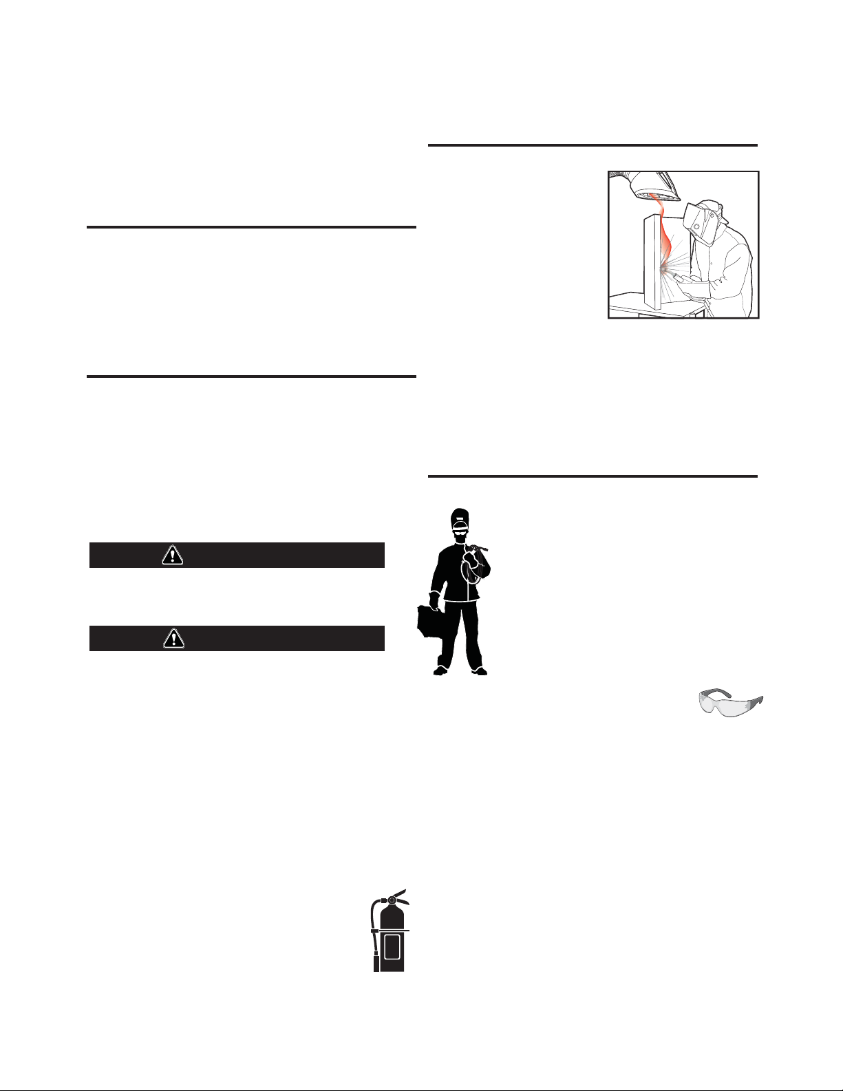
KEEP YOUR HEAD OUT OF THE FUMES.
DON’T get too close to the arc. Use
corrective lenses if necessary to
stay a reasonable distance away
from the arc.
READ and obey the Material Safety
Data Sheet (MSDS) and the warning
label that appears on all containers
of welding materials.
USE ENOUGH VENTILATION or
exhaust at the arc, or both, to keep
the fumes and gases from your breathing zone and the general area.
IN A LARGE ROOM OR OUTDOORS, natural ventilation may be
adequate if you keep your head out of the fumes (See below).
USE NATURAL DRAFTS or fans to keep the fumes away from your
face.
If you de velop unusual symptoms, see your supervisor. Perhaps the
welding atmosphere and ventilation system should be checked.
WEAR CORRECT EYE, EAR & BODY PROTECTION
PROTECT your eyes and face with welding helmet
properly fitted and with proper grade of filter plate
(See ANSI Z49.1).
PROTECT your body from welding spatter and arc
flash with protective clothing including woolen
clothing, flame-proof apron and gloves, leather
leggings, and high boots.
PROTECT others from splatter, flash, and glare with
protective screens or barriers.
IN SOME AREAS, protection from noise may be
appropriate.
BE SURE protective equipment is in good condition.
Also, wear safety glasses in work area AT ALL TIMES.
SPECI AL SI TUATI ONS
DO NOT WELD OR CUT containers or materials which previously had
been in contact with hazardous substances unless they are properly
cleaned. This is extremely dangerous.
DO NOT WELD OR CUT painted or plated parts unless special
precautions with ventilation have been taken. They can release highly
toxic fumes or gases.
Additional precautionary measures
PROTECT compressed gas cylinders from excessive heat, mechanical
shocks, and arcs; fasten cylinders so they cannot fall.
BE SURE cylinders are never grounded or part of an electrical circuit.
REMOVE all potential fire hazards from welding area.
ALWAYS HAVE FIRE FIGHTING EQUIPMENT READY FOR
IMMEDIATE USE AND KNOW HOW TO USE IT.
Page 3
SECTION A:
WARNINGS
CALIFORNIA PROPOSITION 65 WARNINGS
Diesel Engines
Diesel engine exhaust and some of its constituents are known
to the State of California to cause cancer, birth defects, and other
reproductive harm.
Gasoline Engines
The engine exhaust from this product contains chemicals known
to the State of California to cause cancer, birth defects, or other
reproductive harm.
ARC WELDING CAN BE HAZARDOUS. PROTECT
YOURSELF AND OTHERS FROM POSSIBLE SERIOUS
INJURY OR DEATH. KEEP CHILDREN AWAY. PACEMAKER WEARERS SHOULD CONSULT WITH THEIR
DOCTOR BEFORE OPERATING.
Read and understand the following safety highlights. For additional
safety information, it is strongly recommended that you purchase a
copy of “Safety in Welding & Cutting - ANSI Standard Z49.1” from the
American Welding Society, P.O. Box 351040, Miami, Florida 33135 or
CSA Standard W117.2-1974. A Free copy of “Arc Welding Safety”
booklet E205 is available from the Lincoln Electric Company, 22801
St. Clair Avenue, Cleveland, Ohio 44117-1199.
BE SURE THAT ALL INSTALLATION, OPERATION,
MAINTENANCE AND REPAIR PROCEDURES ARE
PERFORMED ONLY BY QUALIFIED INDIVIDUALS.
SAFETY
1.d. Keep all equipment safety guards, covers and
devices in position and in good repair.Keep
hands, hair, clothing and tools away from
V-belts, gears, fans and all other moving parts
when starting, operating or repairing
equipment.
1.e. In some cases it may be necessary to remove safety guards to
perform required maintenance. Remove guards only when
necessary and replace them when the maintenance requiring
their removal is complete. Always use the greatest care when
working near moving parts.
1.f. Do not put your hands near the engine fan. Do not attempt to
override the governor or idler by pushing on the throttle control
rods while the engine is running.
1.g. To prevent accidentally starting gasoline engines while turning
the engine or welding generator during maintenance work,
disconnect the spark plug wires, distributor cap or magneto wire
as appropriate.
1.h. To avoid scalding, do not remove the radiator
pressure cap when the engine is
hot.
ELECTRIC AND
MAGNETIC FIELDS MAY
BE DANGEROUS
2.a. Electric current flowing through any conductor
causes localized Electric and Magnetic Fields (EMF). Welding
current creates EMF fields around welding cables and welding
machines
FOR ENGINE POWERED
EQUIPMENT.
1.a. Turn the engine off before troubleshooting
and maintenance work unless the
maintenance work requires it to be running.
1.b. Operate engines in open, well-ventilated
areas or vent the engine exhaust fumes outdoors.
1.c. Do not add the fuel near an open flame
welding arc or when the engine is running.
Stop the engine and allow it to cool before
refueling to prevent spilled fuel from
vaporizing on contact with hot engine parts
and igniting. Do not spill fuel when filling
tank. If fuel is spilled, wipe it up and do not start engine until
fumes have been eliminated.
2.b. EMF fields may interfere with some pacemakers, and welders
having a pacemaker should consult their physician before
welding.
2.c. Exposure to EMF fields in welding may have other health effects
which are now not known.
2.d. All welders should use the following procedures in order to
minimize exposure to EMF fields from the welding circuit:
2.d.1. Route the electrode and work cables together - Secure
them with tape when possible.
2.d.2. Never coil the electrode lead around your body.
2.d.3. Do not place your body between the electrode and work
cables. If the electrode cable is on your right side, the
work cable should also be on your right side.
2.d.4. Connect the work cable to the workpiece as close as possible to the area being welded.
2.d.5. Do not work next to welding power source.
3
Page 4
SAFETY
ELECTRIC SHOCK
CAN KILL.
3.a. The electrode and work (or ground) circuits are
electrically “hot” when the welder is on. Do
not touch these “hot” parts with your bare skin
or wet clothing. Wear dry, hole-free gloves to insulate hands.
3.b. Insulate yourself from work and ground using dry insulation.
Make certain the insulation is large enough to cover your full area
of physical contact with work and ground.
In addition to the normal safety precautions, if
welding must be performed under electrically
hazardous conditions (in damp locations or while
wearing wet clothing; on metal structures such as
floors, gratings or scaffolds; when in cramped
positions such as sitting, kneeling or lying, if there
is a high risk of unavoidable or accidental contact
with the workpiece or ground) use the following
equipment:
• Semiautomatic DC Constant Voltage (Wire) Welder.
• DC Manual (Stick) Welder.
• AC Welder with Reduced Voltage Control.
3.c. In semiautomatic or automatic wire welding, the electrode,
electrode reel, welding head, nozzle or semiautomatic welding
gun are also electrically “hot”.
3.d. Always be sure the work cable makes a good electrical
connection with the metal being welded. The connection should
be as close as possible to the area being welded.
3.e. Ground the work or metal to be welded to a good electrical (earth)
ground.
3.f. Maintain the electrode holder, work clamp, welding cable and
welding machine in good, safe operating condition. Replace
damaged insulation.
3.g. Never dip the electrode in water for cooling.
3.h. Never simultaneously touch electrically “hot” parts of electrode
holders connected to two welders because voltage
two can be the total of the open circuit voltage of both
welders.
3.i. When working above floor level, use a safety belt to protect
yourself from a fall should you get a shock.
between the
ARC RAYS CAN BURN.
4.a. Use a shield with the proper filter and cover plates to protect your
eyes from sparks and the rays of the arc when welding or
observing open arc welding. Headshield and filter lens should
conform to ANSI Z87. I standards.
4.b. Use suitable clothing made from durable flame-resistant material
to protect your skin and that of your helpers from the arc rays.
4.c. Protect other nearby personnel with suitable, non-flammable
screening and/or warn them not to watch the arc nor expose
themselves to the arc rays or to hot spatter or metal.
FUMES AND GASES
CAN BE DANGEROUS.
5.a. Welding may produce fumes and gases
hazardous to health. Avoid breathing these
fumes and gases. When welding, keep your head out of the fume.
Use enough ventilation and/or exhaust at the arc to keep fumes
and gases away from the breathing zone. When welding
with electrodes which require special ventilation
such as stainless or hard facing (see instructions
on container or MSDS) or on lead or cadmium
plated steel and other metals or coatings which
produce highly toxic fumes, keep exposure as low
as possible and within applicable OSHA PEL and
ACGIH TLV limits using local exhaust or
mechanical ventilation. In confined spaces or in
some circumstances, outdoors, a respirator may
be required. Additional precautions are also
required when welding on galvanized steel.
5. b. The operation of welding fume control equipment is affected by
various factors including proper use and positioning of the
equipment, maintenance of the equipment and the specific
welding procedure and application involved. Worker exposure
level should be checked upon installation and periodically
thereafter to be certain it is within applicable OSHA PEL and
ACGIH TLV limits.
5.c. Do not weld in locations near chlorinated hydrocarbon vapors
coming from degreasing, cleaning or spraying operations. The
heat and rays of the arc can react with solvent vapors to form
phosgene, a highly toxic gas, and other irritating products.
3.j. Also see It ems 6.c. and 8.
5.d. Shielding gases used for arc welding can displace air and
injury or death. Always use enough ventilation, especially in
confined areas, to insure breathing air is safe.
5.e. Read and understand the manufacturer’s instructions for this
equipment and the consumables to be used, including the
material safety data sheet (MSDS) and follow your employer’s
safety practices. MSDS forms are available from your welding
distributor or from the manufacturer.
5.f. Also see item 1.b.
4
cause
Page 5
SAFETY
a
m
WELDING AND CUTTING
SPARKS CAN CAUSE
FIRE OR EXPLOSION.
6.a. Remove fire hazards from the welding area. If
this is not possible, cover them to prevent the
welding sparks from starting a fire. Remember that welding
sparks and hot materials from welding can easily go through
small cracks and openings to adjacent areas. Avoid welding near
hydraulic lines. Have a fire extinguisher readily available.
6.b. Where compressed gases are to be used at the job site, special
precautions should be used to prevent hazardous situations.
Refer to “Safety in Welding and Cutting” (ANSI Standard Z49.1)
and the operating information for the equipment being used.
6.c. When not welding, make certain no part of the electrode circuit is
touching the work or ground. Accidental contact can cause
overheating and create a fire hazard.
6.d. Do not heat, cut or weld tanks, drums or containers until the
proper steps have been taken to insure that such procedures will
not cause flammable or toxic vapors from substances inside.
They can cause an explosion even though they have been
“cleaned”. For information, purchase “Recommended Safe
Practices for the Preparation for Welding and Cutting of
Containers and Piping That Have Held Hazardous Substances”,
AWS F4.1 from the American Welding Society (see address
above).
6.e. Vent hollow castings or containers before heating, cutting or
welding. They may explode.
6.f. Sparks and spatter are thrown from the welding arc. Wear oil free
protective garments such as leather gloves, heavy shirt, cuffless
trousers, high shoes and a cap over your hair. Wear ear plugs
when welding out of position or in confined places. Always wear
safety glasses with side shields when in a welding area.
6.g. Connect the work cable to the work as close to the welding area
as practical. Work cables connected to the building framework or
other locations away from the welding area increase the
possibility of the welding current passing through lifting chains,
crane cables or other alternate circuits. This can create fire
hazards or overheat lifting chains or cables until they fail.
6.h. Also see item 1.c.
CYLINDER MAY EXPLODE IF
DAMAGED.
7.a. Use only compressed gas cylinders containing
the correct shielding gas for the process used
and properly operating regulators designed for
the gas and pressure used. All hoses, fittings,
etc. should be suitable for the application and
maintained in good condition.
7.b. Always keep cylinders in an upright position securely chained to
an undercarriage or fixed support.
7.c. Cylinders should be located:
• Away from areas where they may be struck or subjected
to physical damage.
• A safe distance from arc welding or cutting operations
and any other source of heat, sparks, or flame.
7.d. Never allow the electrode, electrode holder or any other
electrically “hot” parts to touch a cylinder.
7.e. Keep your head and face away from the cylinder valve outlet
when opening the cylinder valve.
7.f. Valve protection caps should always be in place and hand tight
except when the cylinder is in use or connected for use.
7.g. Read and follow the instructions on compressed gas cylinders,
associated equipment, and CGA publication P-l, “Precautions for
Safe Handling of Compressed Gases in
Cylinders,” available
from the Compressed Gas Association 1235 Jefferson Davis
Highway, Arlington, VA 22202.
FOR ELECTRICALLY
POWERED EQUIPMENT.
8.a. Turn off input power using the disconnect
switch at the fuse box before working on the
equipment.
8.b. Install equipment in accordance with the U.S. National Electrical
Code, all local codes and the manufacturer’s recommendations.
6.I. Read and follow NFPA 51B “ Standard for Fire Prevention During
Welding, Cutting and Other Hot Work”, available from NFPA, 1
Batterymarch Park, PO box 9101, Quincy, Ma 022690-9101.
6.j. Do not use a welding power source for pipe thawing.
8.c. Ground the equipment in accordance with the U.S. National
Electrical Code and the manufacturer’s recommendations.
Refer to
http://www.lincolnelectric.com/safety
for additional safety information.
Welding Safety
Interactive Web Guide
for mobile devices
Get t he f ree mobi l e app
http://gettag.
5
Page 6

Table of Contents
Preface
Typographical Conventions Used ........................................................................................................ 1
Cross-References ....................................................................................................................... 1
Text You Type Using the Keyboard ............................................................................................ 1
Keys You Press and Buttons You Click ........................................................................................ 1
Menus You Select .............................................................................................................. ........ 1
Dialog Box, Application Window Titles, a nd F ield Name s .......................................................... 1
Notes, Warnings, and Tips ................................................................................................................... 2
Revision History
General Information
Introduction to Production Monitoring™ ......................................................................................... 1.1
User Roles ............................................................................................................................... 1.1
Weld Profiles ........................................................................................................................... 1.2
Weld Logging .......................................................................................................................... 1.2
E-mail Capability ..................................................................................................................... 1.2
Traceability ............................................................................................................................. 1.3
WeldScore™ ..................................................................................................................................... 1.3
Production Monitoring™ Archit ect u re.............................................................................................. 1.3
Requirements and Limitations .......................................................................................................... 1.4
Server Computer Requirement s ............................................................................................. 1.4
User Computer Requirements ................................................................................................ 1.5
Power Wave® Requirements .................................................................................................. 1.5
Network Requirements ........................................................................................................... 1.6
System Limitations .................................................................................................................. 1.6
Upgrading from Production Monitoring™ 2.1
System Requirements ....................................................................................................................... 2.1
Preparing for the Upgrade ................................................................................................................ 2.1
Running the Production Monitoring™ 2.2 Patch .............................................................................. 2.2
Installing Product ion M onitoring™
Installation Preparat ion .................................................................................................................... 3.1
Prerequisites fo r Inst a lling P r oduc tion Monitoring™ 2.2 ........................................................ 3.1
Determining the Production Monitor ing™ Ve rsion ................................................................. 3.2
Uninstalling Product ion Mo nit or ing™ 2.0 ......................................................................................... 3.2
Uninstalling the Pr o duc t ion M onitoring™ 2.0 Application ...................................................... 3.3
Removing Production Monitoring™ 2.0 F ile s .......................................................................... 3.4
Uninstalling SQL Mana ge ment Studio..................................................................................... 3.4
IM8001 Production Monitoring™User Manual TOC.1
Page 7

Table of Contents
Uninstalling the SQL Ser ve r Instan ce ...................................................................................... 3.5
Removing the Production Monitoring™ Web Site .................................................................. 3.6
Installing Microsoft Inte r ne t Info rm ation S e r vices (IIS) .................................................................... 3.7
Windows XP Professional IIS Installation ................................................................................ 3.7
Windows Server 2003 IIS Installation ...................................................................................... 3.8
Windows Vista IIS Installation ............................................................................................... 3.10
Windows Server 2008 IIS Installation .................................................................................... 3.12
Windows 7 IIS Installation ..................................................................................................... 3.14
Enabling COM+ (Windows Server 2003) ......................................................................................... 3.16
Installing PowerS he ll for Window s Se r ver 2008 ............................................................................. 3.18
Install the Latest Firmware ............................................................................................................. 3.18
Install the Latest Power Wave® Manager ....................................................................................... 3.21
Installing Production Mo nit o ring™ 2.2 S oft w are ............................................................................ 3.23
Production Monitoring™ Administration
Overview .......................................................................................................................................... 4.1
Managing the Asset Tree .................................................................................................................. 4.2
About the Root Asset (or Company Group) ............................................................................ 4.3
Adding Groups ........................................................................................................................ 4.3
Adding a Welding Power Source ............................................................................................. 4.5
Displaying Welding Powe r S o urces t o Other Users ................................................................. 4.8
Enabling/Disabling Data C olle c tion from a Welding Power Source......................................... 4.9
Moving Welding Power Sources and Groups .......................................................................... 4.9
Deleting Welding Powe r Sources and Gr oups ....................................................................... 4.10
Shift Schedule Configura t ion .................................................................................................. ........ 4.10
Next Production Day ............................................................................................................. 4.11
General Shift Schedule Infor mat ion ...................................................................................... 4.12
Managing the Shift Schedule ................................................................................................ 4.13
Example Shift Setup .............................................................................................................. 4.16
Example Shift Setup .............................................................................................................. 4.17
Global Settings ................................................................................................................................ 4.18
Getting the Team Started ............................................................................................................... 4.19
Restricting Access to Administrat ion .............................................................................................. 4.20
Prerequisites ......................................................................................................................... 4.20
IIS 5.1 and IIS 6.0 ................................................................................................................... 4.20
IIS 7.0 and IIS 7.5 ................................................................................................................... 4.23
Using Production Monitoring™
Launching Production Monitoring™ ................................................................................................. 5.1
Overview of the Application ............................................................................................................. 5.1
Asset Tree ............................................................................................................................... 5.2
Report Tabs ................................................................................................................... .......... 5.2
Individual Re
TOC.2 Production Monitoring™ User Manual IM8001
ports ................................................................................................................... 5.3
Page 8

Table of Contents
Panel Resize ............................................................................................................................ 5.3
Overview of Reports ......................................................................................................................... 5.4
Generating Reports ................................................................................................................. 5.4
Report Criteria ........................................................................................................................ 5.4
Report Links ............................................................................................................................ 5.5
Report Page Numbers ............................................................................................................. 5.5
Exporting Report Data ............................................................................................................ 5.6
Refreshing Report Data ........................................................................................................... 5.6
Current Status Tab ............................................................................................................................ 5.7
Current Status by Time Period ................................................................................................ 5.7
System Capacity ...................................................................................................................... 5.9
Production Tab ............................................................................................................................... 5.10
Criteria for the Production Reports....................................................................................... 5.11
Grid Report ........................................................................................................................... 5.12
Weld Profiles Report ............................................................................................................. 5.13
WeldScore™ Report .............................................................................................................. 5.15
Current/Voltage Report ........................................................................................................ 5.16
Wire Feed Speed (and Deposition) Report............................................................................ 5.17
True Energy™ Report ............................................................................................................ 5.19
Duration/Count Report ......................................................................................................... 5.20
Weld Listing Tab ............................................................................................................................. 5.21
Criteria for the Weld Listing Re ports ..................................................................................... 5.21
Grid Report ........................................................................................................................... 5.23
WeldScore™ .......................................................................................................................... 5.25
Current/Voltage Report ........................................................................................................ 5.26
Wire Feed Speed Report ....................................................................................................... 5.27
True Energy™ (and Duration) Report .................................................................................... 5.28
Wire Deposition Report ........................................................................................................ 5.29
Weld Detail Tab .............................................................................................................................. 5.30
Weld Detail Criteria............................................................................................................... 5.30
Weld Detail Report ............................................................................................................... 5.30
Traceability Tab .............................................................................................................................. 5.35
Traceability C rite r ia ............................................................................................................... 5.36
Traceability Repo rt................................................................................................................ 5.37
Downtime Tab ................................................................................................................................ 5.39
Downtime Criteria................................................................................................................. 5.39
Grid Re
Chart Report ......................................................................................................................... 5.41
Fault Detail Tab............................................................................................................................... 5.41
Fault Detail Criteria ............................................................................................................... 5.41
Fault Detail Report ................................................................................................................ 5.43
port ........................................................................................................................... 5.40
Additional Information
IM8001 Production Monitoring™ User Manua l TOC.3
Page 9

Table of Contents
Archive of Data from the Database ................................................................................................. A.1
Archive Frequency ................................................................................................................. A.1
Archive File Name Format ...................................................................................................... A.1
Open an Archive File .............................................................................................................. A.2
Archive File Format ................................................................................................................ A.3
Troubleshooting
Cannot Connect to a Power Source ..................................................................................................B.1
Glossary
TOC.4 Production Monitoring™ User Manual IM8001
Page 10

Preface
Typographical Conventions Used
Before using this guide, it is importa nt to understa nd t he typographic al conventions used to identify and
describe information.
Cross-References
Cross-references t o chapter s, sections, page numbers, hea dings, e t c . a re shown in a n italic t yp e fa ce .
e.g., Refer to Text You Type Using the Keyboard on pa ge 1.
Text You Type Using the Keyboard
Text that you type using the keyboard is shown in a Courier typeface.
e.g., Type John Smi th in t he Name field.
Keys You Press and Buttons You Click
Keys tha t you press on the keyb o ar d and buttons/icons that you click with t hemouse are shown in a bold
sans-serif t y peface.
e.g., Press Enter.
e.g., Click OK to continue.
Menus You Select
Menus and the selections you make from the menus are shown in a bold sans-serif typeface.
e.g., Select Start > Control Panel from the main computer menu.
e.g., Select Tools > Options from the menu.
Dialog Box, Application Window Titles, and Field Names
The titles of dialog boxes and application windows are shown in italics. Field names and selections made
from drop-down menus, etc. are also shown in italics.
e.g., The Print Preview window opens .
e.g., Select All Shifts from the drop-down list.
IM8001 Production Monitoring™User Manual 1
Page 11

Preface
Notes, Warnings, and Tips
Notes, stops and tips appear throughout the manual. They provide additiona l informa t ion t hat is important
for you to know about the topic.
NOTE | A note is an important piece of informatio n.
STOP | You should definitely rea d t he information in a st op t a ble.
It could help y ou prevent a situation f rom which you cannot
recover.
TIP | A tip table helps you w it h s ome interesting or useful
informatio n about using the program.
2 Production Monitoring™ User Manua l IM8001
Page 12

Revision Histor y
Date Change Description
August 2012 Initial release a s IM8001
May 2013 Major revamp and update of manual
IM8001 Production Monitoring™User Manual REV.1
Page 13

Revision History
THIS PAGE INTENTIONALLY LEFT BLANK.
REV.2 Production Monitoring™ User Manual IM8001
Page 14

Chapter 1
General Information
Introduction to Production Monitoring™
Production Monitoring™ is a data colle c tion and reporting technology that is available fo r the la test models
of the Power Wave® fam ily of Welding Power Sources.
The term “Production Monitoring” does not refer to any single featur e . Instead, it refers to the ent ire
collection of feature s an d functionality included with a Welding Power Source. These features include, but
are not limite d to:
Collecting w elding logs complete with statist ic s for each recorded weld.
Setting logical limits on WeldScore™, arc current , a rc vo ltage, wire feed speed, and duration; and
reporting welds t h a t viola te the specified limits.
Creating d istinct Weld Profiles with separate limit se ttings for each pro file.
E-mailing users: Ea c h Welding Power Source has the ability to send e-mails co nt a ining r eports of
weld errors and other information.
Tracking wire usage and providing low-pac k age w arnings for ea c h Welding P ow e r Sour ce.
STOP | Production Monito ring™ does not support consumable
tracking f or dual wire-feeding syst ems.
NOTE | For Production Mo nit oring™ support in U S A and C a nada,
dial 1.800.691.5797. The direct dial number is
1.727.786.0121. The e-mail address is
support@lincolnproductionmonitoring.com
.
User Roles
For the purposes of this documentation, we use the follow ing t erms to help ident ify t he person gener a lly
responsible for the task being discussed. These ar e general terms to help illustrat e the use of Pro duct io n
Monitoring™ in your welding o pe r a tions.
Weld Engineer or Engineer: If you see one of these terms, we generally mean the person in
charge of setting up the weld before the weld is made. In some cases, the Weld Engineer and
the Weld Operator is the same person.
Weld Operator or Operator: This person is the person (or robot) who is actually running the
welder and making the weld.
Production Monitoring™ Administrator: This person is responsible for managing the Production
Monitoring™ application. Ther e could be more t han one, depending on your company’s policies.
IM8001 Production Monitoring™User Manual 1.1
Page 15

Chapter 1. General Information Introduction to Production Monitoring™
Weld Profiles
One of the principal goals of Production Monitoring™ is to report on welds that are outside of user-defined
limits with respect to WeldScore™, current, voltage, wire feed speed and duration. This goal would be
simple to impleme n t if the Welding Power Source were to perform on ly o ne t ype of we ld over a nd o ver.
However, in practica l a pplic ations, this is not the case. The assembly of many different industrial
components requires welds of varying type and length.
The concept of Weld Pr o file s allows the Welding Power Source to apply differ ent limit settings for each
weld that is performed on a certain part. Before the Welding Power Source begins a new weld, the wire
feeder or system controller selects the corresponding Weld Profile. The Weld Engineer can, therefore,
assign one Weld P r o file to each weld required for the part asse m bly .
For more in-dept h info r ma tion about Weld Profiles, please refe r to the Power Wave® Manager User
Manual.
Weld Logging
Production Monitoring™ records lar ge quantities of we ld st atistic s. Eac h log ent ry cont a ins the following
welding stat istics for each weld:
For current, voltage, wire feed speed and duration:
- Minimum
- Maximum
- Average
- Percent above limit
- Perce n t below limit
- Profile m aximum limit
- Profile m inim um limit
True Energy™
Date and time the weld was made
Duration of the weld
Weld stat us a f te r limit checking
Part Number, Consumable Lot and Operator ID
WeldScore™
E-mail Capability
When a Welding Powe r So ur ce ha s ac c e ss to an e-mail server on your net work and you have installed
Production Monitoring™ on the server compute r, the power source can send e-mail notifications to
multiple addre sse s. Each e-mail address can be configured to receive messages fr o m t h e Welding P o w e r
Source upon any of several event conditions.
1.2 P ro d uction Monitoring™ User Manual IM8001
Page 16

WeldScore™ Chapter 1. Gene ra l Information
Traceability
Production M onitoring™ provides you with the ability to re po rt on all th e we lds that were made on a
specific part numbe r , by a spe c ific o per ator or using a specific consumable lot co de. Before a weld is ma de,
this informatio n is c o mm unic a ted to the Welding Power Source, in a variety of wa ys. Every we ld that is
made after this is assigned with these ID numbers unt il a new numbe r is ente red. Production Monitoring™
users can gener ate a traceability report th at looks for this ID from all the Welding Power Sources in the
system. Trac eability solutions are typic a lly customized t o a c ustomer’s specific needs. Please contact
Lincoln Electric for a quotation on your needs.
NOTE | Production Monitoring™ does not support consumable
package t ra c king for dual wire feeding sy stems.
WeldScore™
WeldScore™, a new fe atur e ava ila ble in all third-generation Welding Power Source models (including the
i400, C300, S350, S500 and AC/DC 1000 SD), can be used to support a weld qua lit y c o ntrol program. It
assigns a scor e to welds on a 0% to 100% scale that indic a te s the acceptability of the weld. The score is
based on a comparison to previously trained welding condit ions. Any weld w ith a score of 85% to 90% or
above can be considered, with a reasonable amount of c onfidence, to be an acceptable weld. WeldScore™
can be used independently on the power source or together with Production Monitoring™. Please refer to
the Power Wave® Manager User Manual for more in-depth infor ma tion on WeldScore™.
NOTE | WeldScore™ is not a guarantee of quality and is not
intended t o replace a quality co nt rol system.
Production Monitoring™ Architecture
The Production Monitoring™ system uses a web-based front end (the part that you use to run reports and
set up the application) with a relational database for storing data (weld statistics sent from the Welding
Power Sources). The web-based front end allows users on multiple c o mput e r s to access the welding data
and generate reports using the Production Monitoring™ applic a tion. The main components of the
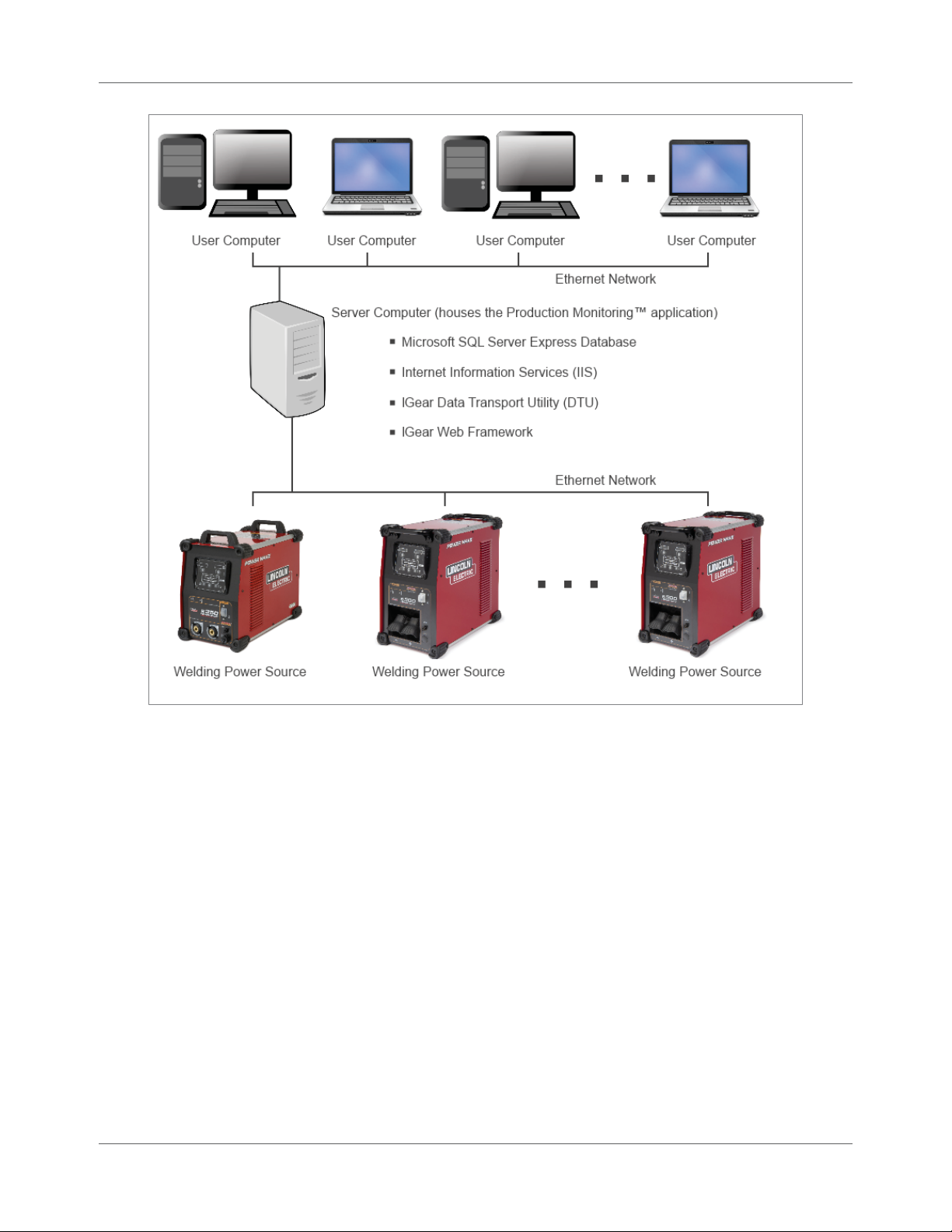
Production Monitoring™ system are:
Microsoft SQL Server Expr ess database for stor in g d ata sent from Welding Power Sources
Microsoft Internet Information Services (IIS) Web Server
IGear Data Transpor t Utility (DTU): This provides the connec tivity from Welding Power Source
to the database on the server computer. This piece of software queries the Welding Power
Sources for information and stores it in t he databa se.
IGear Web Framework: This provides users with a web portal to the database that enables them
to generate various reports.
You install the Production Monito ring™ a pplic a t ion on a single dedica te d ser ve r computer . This server
computer then communicates with the Welding Power Sources over an Ethernet network. Users can be
anywhere and, as long as they have an Ethernet link to the server compute r , they can access the Production
Monitoring™ application.
IM8001 Production Monitoring™ User Manua l 1.3
Page 17
Chapter 1. General Information Requirements and Limitations
Figure 1.1 Production Monitoring™ System
Requirements and Limitations
Server Compu t er Requiremen t s
You install Production Monitor ing™ on a single de dic ate d computer to which all other computers conne ct in
order to access the application. The following ar e th e requir e ments for tha t serve r computer :
Dedicated “alway s on” compute r : This is a server-t ype applica tion designed to run on a
computer tha t is on a ll the time. This application should not be installed on a laptop.
CPU: Dual core, 2 GHz
RAM: 2 GB
An Ethernet (IEEE 802.3–compliant ) 10Mbps 10-Ba seT or 10/ 100-Ba seT ne twork interface card.
Internet browser: Internet Explorer 7 or greater; Firefox; or Chrome
Microsoft Internet Information Services (IIS). Refer to page 3.7 for installa t io n inst r u c tions.
1.4 P ro d uction Monitoring™ User Manual IM8001
Page 18

Requirements and Limitations Chapter 1. General Information
Operating System: Window s 7, Window s Vista , Windows XP P r ofe ssional, Windows Ser ve r 2003
with Service Pack 1 or greater, and Windows Serve r 2008. Production Monit or ing™ support s
both 32-bit and 64-bit operating syste m s.
NOTE | If the system is Windows Server 2003, COM+ must be
enabled. Please see pa ge 3.16 for details.
If the system is Windows Server 2008, PowerShell must be
installe d ma nually. For details on ins t alling PowerShell,
refer to page 3.1 8.
Display: Minimum supported re solut ion is 10 24x768 (16-b it c olor or highe r ).
The Production Monitoring™ screens should alwa ys be expanded to use the full 1024x768
resolution of the monitor. Otherwise, certa in nec e ssary sections of the scre e n may be hidden
from view.
User Computer R equirements
Each user can access Production Monitoring™ from the computer at their desk or from another computer
on the network. The following requirement s apply for that c omputer to view Pr oduction Monitoring™:
Internet Explorer 6 (Service Pack 1) or greater
An Ethernet (IEEE 802.3–compliant ) 10Mbps 10-Ba seT or 10/ 100-Ba seT ne twork interface card
Display: Minimum supported resolution is 1024x768 (16-bit color or higher).
Connection to the same network as the server computer
Power Wave® Requirements
The Power Wave® Welding Power Source that you want to connec t to Production Monit or ing™ must meet
the following requireme nt s:
Ethernet port
- The Power Wa ve® 655, AC/ DC 1000, and a ll third-ge ne r a t ion P owe r Waves (i400, S 350, S 500,
etc.) come standard wit h an Ethernet port, so no a ddit iona l equipme nt is nee de d.
- The Power Wave® 455M, 455M/S TT, 455M Robotic, and 455M/ S TT Robot ic need a K2207-2
Ethernet/DeviceNet Module.
- The Power Wave® 355M, F355i, a nd 405M need a K2436-1 Co mmunic a t ion Interfa ce.
Static IP addre ss se t for each Welding Power Source
- Each Welding Po wer S o urce must have a unique IP address. IP addre sses ar e usually
obtained from your loc a l IT de partment.
- Once you retrieve an IP addre ss for each Welding Power Source, you can use the Lincoln
Electric Power Wave® Manager software to set the IP address in the Welding Power Source.
This software ut ility is available at www.powerwavesoftware.com
The Production Monitoring™ firmwa re revision (in the We lding Power Source) must be revision
5 or greater to use Production Monitoring™ 2.2. You can check the firmware revision using
IM8001 Production Monitoring™ User Manua l 1.5
.
Page 19

Chapter 1. General Information Requirements and Limitations
Power Wave® Manager software on the Diagnostics tab under Production Monitoring >
Register. If the revision is 4 or lower, see page 3.18 for details on updating the firmwa re.
Network Req uirements
Production Monitoring™ uses your computer networ k to communicate with the Welding Power Sources
and the users who want to view data in the application. The following a r e the net work requirement s you
need to meet in order for Production Monitoring™ to run properly:
Network Type: 10 Base-T or 10/100 Base-T network
Cabling: Solid shielded C AT 5 c a bles or better
Connectors: Use RJ-45 environmentally enclosed connectors when connecting the network to
the Welding Power Sourc e .
Connecting Ne tw o r k De vice : The ne twork lines going to the Welding Power Source should go t o
an industrial switch or a switc h with a har dened e nc losure .
Wireless Network Guidelines: A wire le ss networ k r e quir e s an 802.11 bridge. Several cu stomers
have had success using a NETGEAR wireless a dapter (Model: ENCE2001).
System Limitat ions
Table 1.1 compares the two recent versions with r e spe ct to limitations. While Production Monitor ing™ is a
great tool for monitoring your welding operations, please m a k e no te o f the fo llo w ing limitations:
Welds with a tot a l duration less than 0.2 seconds will not be recorde d in Pro duc tion
Monitoring™ 2.2.
Welds wit h a duration less than th e su m o f the Sta rt De la y time plus the End Delay time will be
recorded as a Short Weld.
In Production Monitoring™ 2.2, you have the option to discard Short Welds (i.e., w e lds wit h a
duration less than the sum of the Start Delay time plus the End Delay time).
The maximum number of records the weld table can store is 250,000.
The maximum number of records the event table can store is 250,000.
The maximum number of weld records stored on the Welding P ower S ource itself is 1000. The
oldest rec or d s w ill be replaced with a new recor d w h e n a new record is generated.
NOTE | In the event there is an Ethernet co nnection issue with the
Welding Power Source, the Production Monitoring™ weld
records will be stored in the Welding Power Source up to
the maximum num ber of records. The power s ource will
transfer the data to the Production Monitoring™ database
once the connec tion has been reestablished. Please keep in
mind that if t he W elding Power Source is powered down or
reset for any reason, these stored wel d rec ords will be lost.
Non-synergic modes (such as the Power Mode or Non-Synergic CV modes) are not supported
when you use the Last Digit of Workpoint method for select ing W e ld Profiles. (Please refer t o
the Power Wave® Manager User Manual for more details on this method.)
1.6 P ro d uction Monitoring™ User Manual IM8001
Page 20

Requirements and Limitations Chapter 1. General Information
FANUC® Se r vo To r c h Wire Fe e d Speed (WFS) will not be recorded for olde r soft w are versions of
ArcTool® software and older versions of the Welding Po w e r Sourc e ’s firm w a re. Start ing with the
V7.70P/07 release of the ArcTool® softw are, Ser voTor ch WFS feedbac k is support e d.
The robotic analog interface is not recommended when you use the Last Digit of Workpoint
method for selecting Weld Profiles. (Please refe r to t he Power Wave® Manager User Manual for
more details on this method.)
Production Monitoring™ does not support consumable pac ka ge tracking or the calculation of
Wire Deposition with Dual-Head Wire Fee ders.
When using the Windows XP Pro operating system for the server computer, only five (5) users at
a time can view reports.
When you have multiple machines wit h memory pane ls co nne cte d to your system (e.g., two
wire feeders that each have a memory panel of their own), the Weld Operator should not use
these buttons to choose the Weld Profile for the ir weld. You c ould potentially select the wrong
profile for the weld.
Table 1.1 Limitation Differences between Version 2 .1 and Version 2.2
Item Version 2.1 Version 2.2
Maximum weld duration (sec onds) 6,553 429,496,729
Maximum weld re c ords in Welding Power
Source memory
Shortest weld duration that can be
recorded (seconds)
Minimum total delay (i.e ., S tar t De la y plus
End Delay) (seconds)
Maximum serial number length 16 32
Maximum out-of-lim it tolerance time
(seconds)
TIG and stick welding supported No Yes
WeldScore™ supported No On third-generation We lding
5,000 1,000
0.5 0.2
0.7 0.2
1310.7 85,899,345
Power Sources
IM8001 Production Monitoring™ User Manua l 1.7
Page 21

Chapter 1. General Information Requirements and Limitations
THIS PAGE INTENTIONALLY LEFT BLANK.
1.8 P ro d uction Monitoring™ User Manual IM8001
Page 22

Chapter 2
Upgrading from Production Monitoring™ 2.1
If you already have Production Monitor ing™ 2.1 installed a nd simply nee d t o upgr a de to version 2.2, this
section provides simple information for you to accomplish this as quickly as possible.
STOP | If you have Producti on M onitoring™ 2.0 or l ow er ( or you
need to install for the first time), you must refer to Chapter
3 for instruc tions. Upgrading to t he new v ersion requires
that you unins t all all older versions and install the ne w
version fresh.
System Requirements
The system must meet the requirements liste d on pa ge 1.4 to install and r un t he Product ion Monitoring™
2.2 application. If on e of these requirements is missing, th e installation will fail. For assist ance with these
requirements, please cont act your loca l IT department or contact support at
support@lincolnproductionmonitoring.com
.
Preparing for the Upgrade
To upgrade from Production Mo nit o ring™ 2.1 t o Produc tion Monitoring™ 2.2, you will need the following:
Administ rator permissions o n y o u r server computer.
Production Monitoring™ 2.2 Patch
If you do not have the Production Monitoring™ 2.2 Patch, contact Production Monitor ing™
support at support@lincolnproductionmonitoring.com
software.
A standard installation of Product ion Monit oring™ 2.1 running on the se rve r comput er.
STOP | If your Production Monitoring™ 2.1 insta llation is non-
standard, you will need to contact s upport for assistance
with the upgrade pr oc ess.
A non-stan dard installation wo uld include any instal lation
where the Pro duc t ion Monitoring™ database has been
moved to a diffe rent server or the password for the
Productio n Monitoring™ databa s e has been changed within
Microsoft ® S Q L E nt erprise Manager.
for assistance with obtaining the
IM8001 Production Monitoring™User Manual 2.1
Page 23
Chapter 2. Upgrading from Production Monitoring™ 2.1 Running the Production Monitoring™ 2.2 Patch
Running the Production Monitoring™ 2.2 Patch
The Production Monitoring™ 2.2 Patch upgrades Produc t ion Monit or ing™ 2.1 softw are to the late st
Production Monitoring™ 2.2.x rele a se .
NOTE | If you do not have the patc h file and do not know how to
obtain it, contact Production M onitoring™ support a t
support@lincolnproductionmonitoring.com
Lincoln sales representative.
NOTE | These instructio ns ma y v ary depending on the operat ing
system installed on the server computer.
Procedure Details
or your loca l
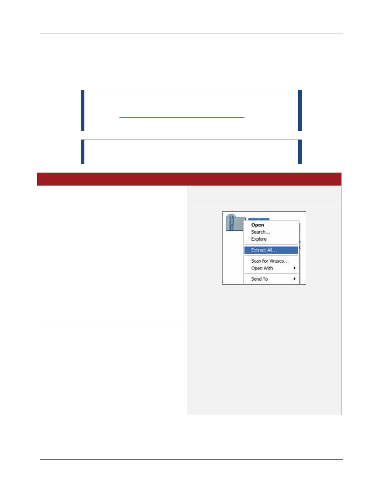
1. Locate the Production Monitoring™ 2.2 patch
file you saved on your computer.
2. Right-click the patch file a nd select Extract All
from the pop-up menu.
3. Double-click the setup.exe file to begin the
installation of the Production Monitoring™
2.2 Patch.
4. When the installation process finishes, c lick
OK to close the applic a tion.
TIP | To find the files easily, crea te an empty
folder on your Desktop and extract the files to that
folder.
This process is aut om a ted and should not require
user involvement once the application begins to run.
The title bar of the a pplic ation should now read
Production Monitoring™ 2.2.
NOTE | If the patch encounters an error duri ng
install or th e s y s t em does not appear to be running
version 2.2, y ou should contact support for
assistance.
2.2 Production Monitoring™User Manual IM8001
Page 24

Chapter 3
Installing Production Monitoring™
If you have a new installation or you need to upgrade from Production Monit or ing™ 2.0 or lower , the
information in th is c hapter provides easy-to-follow instruc tions.
Installation Preparation
This section will guide yo u through the step-by-step proc e ss o f ho w to prep a r e the server compute r fo r th e
Production M onitoring™ software install. This installation section also includes how t o determine which
version is currently running in th e event you are performing a n upgr a de.
Prerequisit es f or Installing Production Monitoring™ 2.2
Before you can begin insta lling Production Monitoring™, you need to make sure that you have met certain
requirements and have certa in informa tion available to you. This helps ensure you have as efficient an
installation a s po ssible.
You must be logged on as an Administrator to the server computer .
Determine the current version being used if you ar e per forming a Pr oduction Monit or ing™
upgrade. Refer to page 3.2 to determine the version installed on your serve r co mputer .
STOP | If you need to upgrade from P roduction Monitoring™ 2.0,
you must completely uninstal l t his v ersion prior to installing
Production Monitoring™ 2.2. Refer to page 3.2 for uninst all
instructions.
If you need to upgrade from Productio n M onitoring™ 2.1,
you must run the P roduction Monitoring™ 2.2 patch. Refer
to Chapter 2 for instructions on running the patch.
The computer name must not contain any underscores (_). Exam ple : If the computer name is
“My_ Computer”, it should be changed to something like “MyComput e r”.
During installatio n , it is best to turn off any Firewalls o r se curity software on the
server computer.
Microsoft Inte r net Information Server (IIS) must be insta lle d before installing Production
Monitoring™. Refer to page 3.7 for information on how to install IIS for your ope rat ing sy st em.
If you are installing the soft w a re on a Windows Se r ver 2003 operating system, che c k to make
sure that Servic e Pa c k 1 or greater is installed. (Right-clic k the My Computer or Computer icon
on the desktop or Start menu and select Properties.)
For the Windows Server 2003 operating system, ver ify t ha t CO M+ is ena ble d. Refer to page 3.16
for information o n ho w to verify if this is enabled.
If your server computer is Windows Ser ve r 2008, Pow e r S hell must be inst a lle d ma nually. Refer
to page 3.18 to install P o w e rShell.
IM8001 Production Monitoring™User Manual 3.1
Page 25
Chapter 3. Installing Production Monitoring™ Uninstalling Production Monitoring™ 2.0
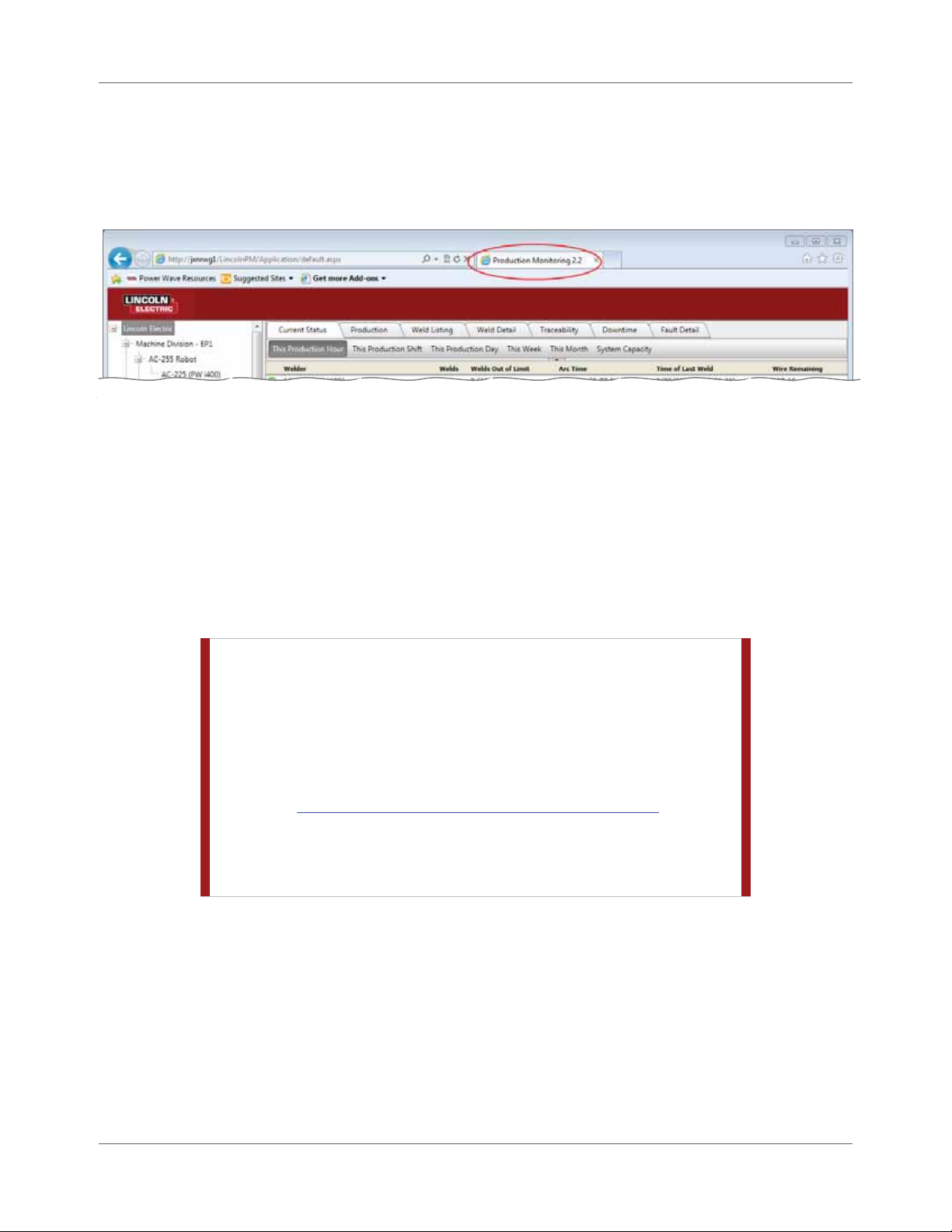
Determini ng the Prod uction Monitoring™ Version
To determine the version of Production Monitor ing™ installe d on your se rver computer, simply launch
Production Monitoring™ on that computer and look at the Inter net browser tab for the applicat ion (Figure
3.1).
Figure 3.1 Verify Production Monitoring™ Version Number
In the event your browser does not display tabs, the applica tion also displays the version number in the
title bar of the window or in the address bar.
If the title bar or tab does not show P r o duction M onitoring™ 2.1, you will then proceed as if your
Production Monitoring™ version is 2.0.
Uninstalling Production Monitoring™ 2.0
This section descr ibe s ho w to uninstall Production Monitoring™ 2.0. You m ust do this prior to installing
Production Monitoring™ 2.2.
STOP | Uninstalling will erase all previous da t a c ollected with
Productio n M onitoring™ 2.0. If you want t o s ave any
previously c ollected data, then d o not c ontinue. Contact
Productio n Monitoring™ suppo rt for assistance in sa v ing
your data. For P roduction Monitoring™ support in the USA
or Canada, dial 1.800.691.5797. The direct dial number is
1.727.786.0121. You can also e-mail support at:
support@lincolnelectricproductionmonitor ing.com
Support will need to log in to the server computer remotely
in order to bac k up the previous database from Production
Monitoring ™ 2 .0.
3.2 P ro d uction Monitoring™ User Manual IM8001
Page 26
Uninstalling Production Monitoring™ 2.0 Chapter 3. Installing Production Monitoring™
Uninstalling the Production Monitoring™ 2.0 Application
As you begin to uninstall P r oduc tion Monitoring™ 2.0, you will uninstall various applic ations that comprise
the Production Monitoring™ “system”. This section explains how to remove the Production Monitoring™
2.0 software application. Ke e p in mind these steps may va ry depending on t he compute r Operating
System.
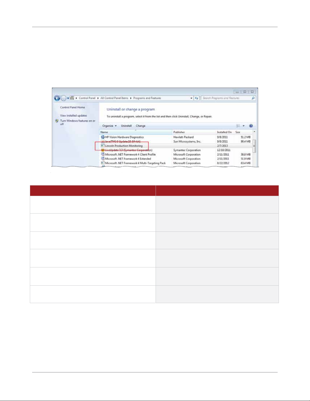
Figure 3.2 Uninstalling Software
Procedure Details
1. Select the Start > Control Panel from the
computer’s main program menu.
2. Double-click the Add or Remove Programs icon.
3. Locate Lincoln Production Monitoring in the list
of software.
4. Click the Remove button.
5. Select the Uninstall button.
6. Click the Close button when the system finish es
uninstalling Product ion Monit or ing™ 2.0.
In newer versions of the Windows operating
system, the option is called Programs and Features.
See Figure 3.2.
The system prompts you to confirm that you want
to uninstall the software.
The system uninstalls the program and will inform
you when it is co mp le te.
IM8001 Production Monitoring™ User Manua l 3.3
Page 27

Chapter 3. Installing Production Monitoring™ Uninstalling Production Monitoring™ 2.0
Removing Production Monitoring™ 2.0 Files
This section describes how to remove any remaining Product ion Monit or ing™ 2.0 files from the default
installation location on the serve r comput er. Keep in mind t he se inst ructions ma y va ry depending on the
operating system installed on your computer.
Procedure Details
1. Open the Start menu and click My Computer.
2. Double-click the Local Disk (C:) icon.
3. Open the Program Files folder.
4. Open the Lincoln Electric folder.
5. Right-click the Production Monitoring folder
and select Delete from the pop-up me nu.
6. Click Yes.
Depending on your operating system, the option
could be called Computer . The contents of the
computer display.
The syste m d isp lays the folders sto r ed on your
local drive.
TIP | If there is no Production Monitoring folder
when you open the Lincoln Electric folder, you can
move to the next s ec t ion a nd skip the remaining
steps.
The system prompts you to confirm the deletion of
the folder.
Uninstalling SQL Management Studio
You must uninstall SQL Management Studio if you have it inst a lle d on your comput e r.
Procedure Details
1. Select the Start > Control Panel from the
computer’s main program menu.
2. Double-click the Add or Remove
Programs icon.
3. Locate Microsoft SQL Server Management
Studio in the list of software.
4. Click the Remove button.
5. Click Yes if prompted to confirm you want to
remove the program.
3.4 P ro d uction Monitoring™ User Manual IM8001
In newer versions of the Windows operating system,
the option is calle d P rog ra ms a nd Features.
The system proceeds with uninstalling Microso ft SQL
Server Management Studio Express.
Page 28

Uninstallin g Production Monitoring ™ 2.0 Chap t er 3. Installing P r oduction Monitoring™
Uninstalling the SQL Server Instance
After you uninstall Microsoft SQL Se rver Manage me nt St udio Expr e ss, you need to remove the SQL
database used in version 2.1 so you can start fresh with version 2.2.
To remove the SQL Server Instance:
Procedure Details
1. Select the Start > Control Panel from the
computer’s main program menu.
2. Double-click the Add or Remove
Programs icon.
3. Locate Microsoft SQL Server 2005 in the list
of software.
4. Click the Remove button.
In newer versions of the Windows operating system,
the option is calle d P rog ra ms a nd Features.
The system proceeds to uninstall t he insta nc e.
During th e process, the syste m st ops and displays
the Component Selection window.
5. Choose LINCOLN: Database Engine and
click Next.
6. Click Finish to continue.
7. Exit the Add or Remove Programs window
when the process is complete.
IM8001 Production Monitoring™User Manual 3.5
STOP | Only remove the LINCOLN: Database
Engine entry. DO NOT remove any other
databases.
The syste m di splays a confirmatio n m essage.
The syste m completes the uninst all process.
Page 29

Chapter 3. Installing Production Monitoring™ Uninstalling Production Monitoring™ 2.0
Removing the Production Monitoring™ Web Site
This section outlines the steps necessary to completely remove the Production Monitoring™ 2.0 website
from the server computer.
Procedure Details
1. Select the Start > Control Panel from the
computer’s main program menu.
2. Double-click the Administrative Tools icon.
3. Double-click the Internet Information
Services shortcut.
4. Click the plus sign ( + ) next to Machine
Name (local computer) to expand it.
5. Click the plus sign ( + ) next to the Web Sites
folder to expand it.
6. Click the plus sign ( + ) next to Default Web
Site folder to expand it .
The Control Panel opens.
The Administrative Tools window opens.
The system opens the Internet Information Services
window.
Where MachineName is the name of your computer
7. Right-click the LincolnPM option and select
Delete from the pop-up menu.
8. Click Yes to delete the item.
9. Right-click the IGear.Lincoln.Configuration
option and select Delete from the popup menu.
3.6 Production Monitoring™User Manual IM8001
The system prompts you to confirm the deletion.
The system prompts you to confirm the deletion.
Page 30

Installing Microsoft Internet Information Services (IIS) Chapter 3. Installing Production Monitoring™
Procedure Details
10. Click Yes to delete the item.
11. Restar t your computer .
After uninstalling a nd r e m oving a ll pr evious items, you
must restart your computer before continuing.
Installing Microsoft Internet Information Services (IIS)
Production Monitoring™ is an int ernal w e b-based applica tion that allows you and other users to access
data collected from the Welding P ower Sources co nne c ted to the applica t ion. In order for you and others
to access this data, you need to set up the server computer to be a web server. You do this by activating or
installing Micr o soft’s Internet Information Service s (or IIS) components.
TIP | When installing IIS on o lder computers, please be sure you
have the Windows installation C D for your operating
system. Check w it h y our local IT department for more
information.
The instructions are slight ly diffe r e nt de pending on th e Opera t ing S ystem (OS) of your Production
Monitoring™ server comput er. Click the link below to navigate directly to the section related to your OS.
Windows XP Professional
Windows Server 2003
Windows Vista
Windows Server 2008
Windows 7
Windows XP Prof essional IIS Installation
With Windows XP P r o fe ssio nal, IIS is not installed by default. Follow the instructions below to inst a ll IIS.
Procedure Details
1. Log in to the server computer as the
administrator user.
2. Insert the original Microsoft Operating
System d isk .
3. Choose the Install Windows XP option under
the What do you want to do? question.
Contact your IT department for appropriate user
name and password if necessary.
The Welcome to Microsoft Windows XP should
appear.
The Windows Components Wizard window opens.
IM8001 Production Monitoring™ User Manua l 3.7
Page 31

Chapter 3. Installing Production Mon ito ring™ Installing Micros o ft Inte rn et In fo rmation Services (IIS)
Procedure Details
4. Place a check mark next to Internet
Information Services (IIS) and click Next.
The syste m in stalls IIS and comple tes the process.
Congratulations! You have activated IIS for your
server computer. Continue to page 3.18 to install
or upgrade Power Wave® Manager.
Windows Server 2003 II S Installat ion
With Windows Server 2003, IIS is installed by de fa ult, but you need to let the system know you want to use
it. Follow the inst r u c t io ns below to add the IIS components.
Procedure Details
1. Log in to the server computer as the
administrator user.
2. Select the Start > Control Panel from the
computer’s main program menu.
3. Double-click Add or Remove Programs.
Contact your IT department for appropriate user
name and password if necessary.
The Add or R emove Programs L i stopens.
3.8 Production Monitoring™User Manual IM8001
Page 32

Installing Microsoft Internet Information Services (IIS) Chapter 3. Installing Production Monitoring™
Procedure Details
4. Click the Add/Remove Windows
Components button.
5. Place a check mark next to Application
Server and click the Details but t o n.
The Windows Components Wizard wi nd ow o pen s .
The Applicat io n Se rve r window opens.
6. Place a check mark next to Internet
The Internet Information Services (IIS) window opens.
Information Services (IIS) and click the
Details button.
IM8001 Production Monitoring™ User Manua l 3.9
Page 33

Chapter 3. Installing Production Mon ito ring™ Installing Micros o ft Inte rn et In fo rmation Services (IIS)
Procedure Details
7. Place a check mark next to World
Wide Web Service and click the
Details button.
8. Place a check mark next to Server Side
Includes and click OK.
9. Click OK on any open windows until you
get back to the Windows Component
Wizard.
The World Wide Web Service window opens.
10. Click Finish.
The syste m c o m p letes the installatio n .
Congratulations! You have activated IIS for your
server computer. If you haven’t enabled COM+ on
your server or you’re not sure, continue to page 3.16.
Otherwise, continue t o page 3.18to install or update
Power Wave® Manager.
Windows Vista IIS Installat ion
With Windows Vista, the installation files were saved to the computer when the Operating System was
installed on the computer . Since you want to turn the computer into a n inter nal web server, you nee d to
run the IIS installation to enable the appropriate components.
Procedure Details
1. Log in to the server computer as the
administrator user.
2. Select the Start > Control Panel from the
computer’s main program menu.
Contact your IT department for appropriate user
name and password if necessary.
3.10 Production Monitoring™User Manual IM8001
Page 34

Installing Microsoft Internet Information Services (IIS) Chapter 3. Installing Production Monitoring™
Procedure Details
3. Open Programs and Features.
4. Click the Turn Windows features on or off
link under Tasks.
5. Click the plus ( + ) icon next to Internet
Information Services to expand the list.
The Programs and Features list opens.
The Windows Features wi n d o w opens.
6. Verify there is a check mark next to IIS 6
Management Compatibility and all of the
options under it.
7. Click the plus ( + ) icon next to Application
Development Features to expan d th e li s t.
IIS 6 Management Console
IIS 6 Scripting Tools
IIS 6 WMI Compatibility
IIS Me taba se a n d IIS 6 configuration
compatibility
IM8001 Production Monitoring™User Manual 3.11
Page 35

Chapter 3. Installing Production Mon ito ring™ Installing Micros o ft Inte rn et In fo rmation Services (IIS)
Procedure Details
8. Verify there is a check mark next to the
appropriate options.
9. Click the plus ( + ) icon next to Common
HTTP Features to expand the list.
10. Verify there is a check mark next to the
appropriate options.
11. Click OK to close the window.
ASP
ASP.NET
Server Side Includes
Static Content
Congratulations! You have activated IIS for your
server computer. Continue to page 3.18 to install or
upgrade Power Wave® Manager.
Windows Server 2008 II S Installat ion
The installation files we r e saved to the computer when the Windows Server 2008 operating syste m w a s
installed on the computer . Since you want to turn the computer into an internal web server, you need to
tell the server that it need s to play t he ro le of a web ser ver (i.e ., one that hosts a web site and allows other
users to connect). Follow the instruct ions below to add the IIS components.
Procedure Details
1. Log in to the server computer as the
administrator user.
2. Select Server Manager from the Start menu.
Contact your IT department for appropriate user
name and password if necessary.
The Server Manager window opens.
3.12 Production Monitoring™User Manual IM8001
Page 36

Installing M icro s o ft Inte rnet Information Services (IIS) Chapter 3. Installing Produ ction Monitoring™
Procedure Details
3. Right-click the Roles option and select Add
Roles from the pop-up menu.
4. Click Next on the Befor e You Begin page if
it appears.
5. Place a check mark in the Web Server (II S)
checkbox and click Next.
6. Click the Add Required Features button.
7. Click Next on the Serve r Roles screen.
The Add Roles Wizard window opens.
The Select Server Ro les w indow appears.
The system prompts you to add the features
required for Web Server (IIS).
The Web Server (IIS) scre en appears.
8. Click Next on the Web Server (IIS)screen.
9. Click the plus ( + ) icon next to Web Server to
expand the list.
10. Click t h e plus ( + ) icon ne xt t o Application
Development to expand the list.
The Select Role Service sscreen displa y s.
IM8001 Production Monitoring™User Manual 3.13
Page 37

Chapter 3. Installing Production Mon ito ring™ Installing Micros o ft Inte rn et In fo rmation Services (IIS)
Procedure Details
11. Verify there is a check mark next to the
appropriate options.
12. Click t h e plus ( + ) icon ne xt t o Management
Tools to expand the list.
13. Click t h e plus ( + ) icon ne xt t o IIS 6
Management Compatibility to expand the list.
14. Verify there is a check mark next to IIS 6
Management Compatibility and all of the
options under it.
15. Click Next to continue the installation.
16. Verify your sele c t ions and click Install.
ASP.NET
This should produce a dialog requesting t he
addition of ISAPI Extensions. Add them as
well.
ASP
Server Side Includes
IIS Metabase Compatibility
IIS 6 WMI Compatibility
IIS 6 Scripting Tools
IIS 6 Management Console
The Confirm Ins t a llation Selections screen appears.
The system inst alls all the components necessary to
turn your computer into an internal web server for
Production Monitoring™.
17. Click the Close button when the installation is
complete.
Congratulations! You have activated IIS for your
server computer. Continue to page 3.18 to install
PowerShell on your server computer.
Windows 7 IIS Inst allation
With Windows 7, the installation files were saved to the computer when the Operating System was
installed on the computer . Since you want to turn the computer into an internal web server, you need to
run the IIS installation to ena ble the appropr iate componen t s so users and Welding P ow er Source s can
access Production Monitoring™.
Procedure Details
1. Log in to the server computer as the
administrator user.
2. Select the Start > Control Panel from the
computer’s main program menu.
Contact your IT department for appropriate user
name and password if necessary.
3.14 Produ ct io n Monitoring ™ User Manu al IM8001
Page 38

Installing Microsoft Internet Information Services (IIS) Chapter 3. Installing Production Monitoring™
Procedure Details
3. Open Programs and Features.
4. Click the Turn Windows features on or off
link in the pane on t he le ft .
The Programs and Features list opens.
TIP | If you don’t see Programs and Features, try
changing the View by drop-down from Category to
Small icons.
The Windows Features window opens.
5. Click the plus ( + ) icon next to Internet
Information Services to expand the list.
6. Click the plus ( + ) icon next to Web
Management Tools to expand the list.
7. Verify there is a check mark next to the
appropriate options and sub-options.
IIS 6 Management Compatibility
- IIS 6 Management Console
- IIS 6 Scripts
- IIS 6 WMI Compatibility
- IIS Metabase and IIS 6 configuration
compatibility
IIS Management Console
IIS Management Scripts and Tools
IIS Management Service
8. Click the plus ( + ) icon next to World Wide
Web Services to expand the list.
IM8001 Production Monitoring™User Manual 3.15
Page 39

Chapter 3. Installing Production Monitoring ™ Enabling COM+ (Window s Se rver 2003)
Procedure Details
9. Click the plus ( + ) icon next to Application
Development Features to expan d th e li st.
10. Verify there is a check mark next to the
appropriate options.
11. Click t h e plus ( + ) icon ne xt t o Common
HTTP Features to expand the list.
12. Verify there is a check mark next to the
appropriate options.
13. Click t h e plus ( + ) icon ne xt t o Security to
expand the list.
14. Verify there is a check mark next to the
appropriate options.
.NET Extensibility
ASP
ASP.NET
ISAPI Extensions
ISAPI Filters
Server-Side Includes
Default Document
Static Content
Basic Authentication
Request Filtering
Windows Authentication
15. Once you have the appropriate options
checked, click OK to install.
Windows installs IIS with the options you’ve chosen.
Once the installation is complete , the system may
prompt you to restart your computer. Be sure to do
so if prompted.
Congratulations! You have activated IIS for your
server computer and can close the Programs and
Features window. Continue to page 3.18 to install or
upgrade Power Wave® Manager.
Enabling COM+ (Windows Server 2003)
Production Monitoring™ communica tes data from the Welding Po w e r Source to the database and then out
to the users connected to the web applica tion through the server computer. To allow all components to
talk to each other effectively on Windows Server 2003, you nee d to enable COM+ for Production
Monitoring™.
Procedure Details
1. Log in to the server computer as the
administrator user.
2. Select Start > Control Panel from the
computer’s main menu.
Contact your IT department for appropriate user
name and password if necessary.
3. Click Add or Remove P rog ra ms.
3.16 Produ ct io n Monitoring ™ User Manu al IM8001
Page 40

Enabling COM+ (Wind o w s Serve r 2003) Chapter 3. Installing Production Monitoring™
Procedure Details
4. Click Windows Components.
5. Place a check mark next to Application
Server and click the Details but t o n.
The Windows Components Wizard opens.
The Applicat io n Se rve r window opens.
6. Make sure there is a check mark next to
Enable network COM+ access.
7. Click OK to close the window.
8. Click Next on the Windows
Components Wiza rd .
9. Click the Finish button once the installation
is complete .
IM8001 Production Monitoring™ User Manua l 3.17
The system enables the communication
components.
The system may prompt you to restart the
computer. Be sure to do so. Once completed,
proceed to page 3.18 to install or update the Powe r
Wave® Manager.
Page 41

Chapter 3. Installing Production Mo n ito rin g ™ Installing Po w e rShell fo r W in d o ws Se rver 2008
Installing PowerShell for Windows Server 2008
Windows PowerShell provide s co mmunic a t ion and management compone nts for the Production
Monitoring™ web application, allowing the Welding Power Sources and database to communicate with the
web pages. Windows Server 2008 includes PowerS he ll, but you need to inst a ll it manua lly. The follow ing
steps describe how to install P owe rS hell on Windows Server 2008.
Procedure Details
1. Log in to the server computer as the
administrator user.
2. Select Start > Server Manager from the
computers main menu.
3. Click the Features option in the left pane.
4. Click the Add Features link on the right.
5. Place a check mark in the Windows
PowerShell checkbox.
6. Click Next.
7. Click the Install butto n.
8. Once PowerS he ll is do ne installing, click the
Close button.
Contact your IT department for appropriate user
name and password if necessary.
Once complet e d, pr oce e d to page 3.18 to insta ll or
update the Power Wave® Manager.
Install the Latest Firmware
“Firmware ” is the memo r y a nd progr a m ming code within the Welding Power Source that provides the
control program for the machine. Making sure you ha ve t he latest firm w are ensures that you have the
latest features availa ble for the powe r source, including the most r e cent ver sion of the Production
Monitoring™ software .
To install the latest firmware:
Procedure Details
1. Open your browser and go to
www.powerwavesoftware.com.
2. Enter your username and password in the Email
and Password fields and click Sign In.
OR
Click the Register Today link to create an
account.
3.18 Produ ct io n Monitoring ™ User Manu al IM8001
The Login page displays.
If you’re creating a new account, follow t he
onscreen instructions and return to this st ep
when finished.
Once yo u log in , t h e system displays the Power
Wave Resource Center.
Page 42

Install the Latest Firmwa re Chapter 3. Inst alling Production Monitoring™
Procedure Details
3. In the Quick Links sect ion, click the Power
Wave®, Power Feed®/MAXsa® Software link.
4. Click the Download Power Wave® Bundle-FREE
button to run the update.
The system displays a page co ntaining t he
Download Power Wave® Bundle-FREE button.
NOTE | Depending on your Windows version,
you may have to click Run or Allow to permit
your system to launch the file.
The system opens the Lincoln Electric System
Update Utility window where you tell t he ut ility
how to find the Welding Power Source you want
to update.
5. Choose the Connect throu gh E thernet option
and enter the IP address of the Welding Power
Source you want to update.
IM8001 Production Monitoring™User Manual 3.19
TIP | If there is an IP address a lready
displaye d, it is the IP address of the las t
Welding Pow er Source that was c o nnected.
Be sure you enter the correct address f or t he
current We lding Power Source you want to
Page 43

Chapter 3. Installing Production Monitoring™ Install the Latest Firmware
Procedure Details
update.
You can enter the IP address for the Welding
Power Source in one of two ways:
Type the specific IP address into t he I
know the IP address of the welder field.
Choosing the I do not know the IP
address of the welder option. The
update utility scans your network and
displays a list of W e lding P o w er Source
IP addresses on the same subnet.
NOTE | If this Welding P ow er Source has
older firmware, the IP address will not show up
using this method.
TIP | If you run into a problem, please refer to
the Troubleshooting section (Append ix B).
6. Click the Connect butto n once you have
entered the IP address for the power source
you are updating.
The soft ware scans the We ld in g Power Source to
verify if the fir mware currently on the machine is
up to date.
7. If the firmware is not up to date, you must click
Continue to update the Welding Power Source.
3.20 Produ ct io n Monitoring ™ User Manu al IM8001
The system proceeds with the update.
If the firmware is a lr ea dy up to dat e , yo u will
receive the message Update not req uired and
you can click Exit to close the window.
Page 44

Install the Latest Power Wave® Manager Chapter 3. Installing Production Monitoring™
Procedure Details
8. Exit the program once the firmware has
finished updating.
9. Repeat steps 3 through 8 for each power source
you need to update.
Install the Latest Power Wave® Manager
Once you update the Welding Power Source(s), you need to upgrade to the late st version of Pow e r Wave ®
Manager on the server computer or install the software for the first time. Power Wave® Manager is a
software applic a tion that allows you to manage a multitude of set tings and configuration options within th e
Lincoln Electric Power Wave® family of Welding P o w e r So urce s. It a lso pr ovides in-depth diagnostics of the
Welding Power Sour c e’s hardware and firmware to help identify and elim ina t e issues wit h welding or
configuration.
TIP | If you already have P ow e r Wave® Manager installed, you
can simply ope n t he s oftware. Depending on y our v ersion
of the software, the sy st em a utoma tically checks for and
installs any updates. If it doesn’t do t his a utomatically, you
can click the Check for Updates button.
Procedure Details
1. Open your browser and go to
www.powerwavesoftware.com
.
2. Enter your username and password in the
Email and Password fields and click Sign In.
The Login page displays.
These are the same credentials you used when
updating the Welding Power Sour ce fir mw are.
Once yo u log in , t h e system displays the Power
Wave Resource Center.
3. In the Quick Links sect io n, c lic k the Power
IM8001 Production Monitoring™ User Manua l 3.21
The system displays a page co ntaining t he
Page 45

Chapter 3. Installing Production Monitoring™ Install the Latest Power Wave® Manager
Procedure Details
Wave® Utilit ies link. Download Power Wave® Utilities FREE button.
4. Click the Download Power Wave® Utilities
FREE button to run the update.
5. Select your language from the drop-down
and click OK.
NOTE | Depending on your Windows version,
you may have to click Run or Allow to permit your
system to launch the file.
The syste m d isp lays the Installer Langua ge dialog.
If you are running an older version of Power Wave®
Manager, the system pr o m pt s y o u to remove the
old version. Click OK to allow the installer to
remove the old version.
If this is a new inst a llation (or once the old version
is removed), t he system displays the installation
welcome windo w.
6. Click Next on the Welcome screen to move to
the License Agreement and continue the
installation.
7. You must accept the License Agreement and
click Next to continue.
8. Leave the default value in the Destination
Folder field and click Install.
9. Click the Finish button to exit the installer.
3.22 Production Monitoring™User Manual IM8001
The syste m extracts files and installs the Power
Wave® Utilities o n yo ur c o mputer. Once it is
complete, the final page of the Setup Wizard
opens.
Congratulations! You have installed Power Wave®
Manager and can now configure your Welding
Power Source.
Page 46

Installing Production Monitoring™ 2.2 Software Chapter 3. Installing Production Monitoring™
Installing Production Monitoring™ 2.2 Software
Once you have removed any old versions of Production Monitoring™, insta lle d IIS a nd a ny other nece ssary
components (depending on your operat ing system), you are now read y to install Production Monitoring™.
STOP | Be sure that you have completed all the preliminary
requirement s on the preceding pages before you continue.
Your installa tion could fail if you ha v e not met these
requirements.
NOTE | Installation time i s a pproximately 45 minutes.
Procedure Details
1. Insert the installa tion CD into the disk drive
or locate the downloaded files.
2. Double-click Setup.exe from the installatio n
CD or your downloaded file s.
3. Select your language from the Language
drop-down and click Next.
4. Place a check mark in the I accept the terms
of the License Agreement checkbox and
click Next.
You either received a CD, or the Lincoln Electric team
provided you online a c c e ss to a ZIP file to download
and extract.
The Lincoln Production Monitoring welcome
windowopens.
The software’s License Agreement displays.
The syste m p r o m p ts you for the installation path for
Production Monitoring™.
The default location is:
C:\Program File s\Lincoln Electric
IM8001 Production Monitoring™User Manual 3.23
Page 47

Chapter 3. Installing Production Monitoring™ Installing Production Monitoring™ 2.2 Software
Procedure Details
5. Leave the default value and click Next.
If the directory does not exist, the system prompts
you to create it. Click Yes.
The installer continues and installs all componen t s.
At this point, the installation takes a while to
complete. No user interac t ion is require d during this
time.
TIP | You may notice the tit le bar of the
application reads “(Not Responding)”. This is
expected du ring the install and does not indicate a
problem. In ad dition, other windows open and
close throug hout the installation. This is also
expected.
Once the installation is complete , the Summary
screen d isp la y s.
6. Click Finish.
3.24 Production Monitoring™User Manual IM8001
Congratula tions! You have installed thenew
Production Monitoring™ softwa re. Continue to
Chapter 4 for deta ils o n c o nfigur ing the system.
Page 48

Chapter 4
Production Monitoring™ Administration
Overview
Once you have Production Monitoring™ installed, you c a n now configure t he system t o meet your
company’s reporting needs.
Figure 4.1 Production Monitoring™ Pages
There are two web pages for Production Monitoring™:
Administration page: You can access this web page only through t he serve r comput er.
Main application page : With the ma in page of Production Monitoring™, users can view data and
reports from the Welding Power Sources. Users can access this thr ough a ny c o mputer with
access to the server. You can also access the main p a g e directly from th e server computer .
This chapter explains the Administration page and how to use it to configure Production Monitoring™.
Chapter 5 explains the main applic a tion page of Production Monitoring™ for all users.
On the Administration page, you can:
add and delete Welding Power Source s
establish shift settings
set global units of measure
IM8001 Production Monitoring™User Manual 4.1
Page 49

Chapter 4. Production Monitoring™ Administration Managing the Asset Tree
Managing the Asset Tree
The Asset Tree is where users select the Welding Powe r S ources or the Group of power sources for which
they would like to see data. Based on the choice they make in the Asset Tree on the left of the web page,
the report they select on the right side displays the weld data fr om that power sourc e or group of power
sources.
Figure 4.2 Asset Tree on the Main Application Page
In order for there to be Welding Power Sou rces and Groups of power sources, you must create the
hierarchy of the Asset Tree here on the Administration page of Production Monitoring™. Typically, this
hierarchy matches the configurat ion of t he welders out on the product ion floor.
The Asset T r ee has two types of ite m s: a Group and a single Welding Power Source.
A Group entry organizes Welding Power Sou rces logically. You use these groups to make it
easier to review data for Welding Power Sources. Grouping Welding Power Sources together in
logical a r rangements also m a kes it much easier t o ge n erate reports on pow er sources that are
related (e.g., in the same area on the floor). See page 4.3 for details on the uppermost Group
(called the “Root Asset”).
A Welding Power Source entry simply ident ifies a Welding Power Source machine for w hich you
would like to co lle ct dat a . A Welding P ow er Source entry must always be within a Group entry.
If you click on a Group, the system displays the properties of that group (Figure 4.5 on page 4.4). If you
click on a We lding P o w er Source, the system displays the properties and configura t ion opt ions for t ha t
power source (Figure 4.6 on page 4.5).
4.2 P ro d uction Monitoring™ User Manual IM8001
Page 50

Managing the Asset Tree Chapter 4. Production Monitoring™ Administration
About the Root Asset (or Company Group)
When you first install Production Monitoring™ and access the Administration page, the system d isp la y s the
empty “Root Asset” (Figure 4.3). This uppermost Group is the level at w h ic h you crea te your c o mp a n y sit e.
All other Groups and Welding Power Sources for that company appear inside the company group.
Figure 4.3 Root Asset on the Asset Tree
No other Group or Welding Power So urce can be at the same level as the company group. For example, in
Figure 4.4, the Groups calle d Line 1 and Line 2 are organized under neat h (or inside) the Advanced
Manufacturing Group. If we were to click the minus icon ( ) next to Advanced Manufacturing to collapse
the list, both Line 1 and Line 2 would be hidden from view. This is the recommended alignment a nd allows
us to see data for the entire company.
The image on the right in Figure 4.4 is not a standard alignment and generally not reco mmended. Line 1
and Line 2 were saved at the same level as the company Group Advanced Manufacturing. If the users
wanted to see data for the entire company, they would be unable to do so.
Figure 4.4 Proper Alignment of Groups and Power Sources
Adding Groups
In general, you create Groupsin the Asset Tree to help you organize Welding Power Sou rce entries, giving
the Asset Tree a logical structure that reflects your production floor and making it easy to find and view
welding data for spec ific m a c hines. For example, your company ha s five (5) lines of power sources with
IM8001 Production Monitoring™User Manual 4.3
Page 51

Chapter 4. Production Monitoring™ Administration Managing the Asset Tree
three (3) machines o n eac h line . Yo u would cre a te five (5) Group entries in the Asset Tree with three (3)
Welding Power Source entries under each one.
Figure 4.5 Groups in the Asset Tree
In addition, instead of running a report only for a single We lding P ower Source or only for all the Welding
Power Sources in a company, a Group allows you to limit the report to only those Weldi ng Power Sources
that are listed under a partic ula r Group. Please keep this in mind when organizing the Asset Tree.
To add a Group to the Asset Tree:
Procedure Details
1. Select the Group entry under which you want
to add a new Group.
2. Click Add A New Asset at the top of the
tree list.
The system adds a new entry under the Group you
selected.
4.4 P ro d uction Monitoring™ User Manual IM8001
Page 52

Managing the Asset Tree Chapter 4. Production Monitoring™ Administration
Procedure Details
3. Click the new asset.
4. Edit the Name field to meet your needs.
5. Make sure you have Group select ed in the
Tree Node Type drop-down.
6. Click Save Changes.
The syste m d isp lays the Asset Properties.
For example, John at Advanced Manufactur ing
has his machines organized in lines so he t ypes
Line 1 for his first group.
Congratulations! You’ve create d your Group entry
and can now add Welding Powe r S ources or other
Groups to it.
You can repeat these steps to add all of your
groups now or you can create one complete group
at a time. Page 4.5 explains adding Welding
Power Sources to the Asset Tree.
Adding a Welding Power Source
A Welding Power Source entry is a connection to the welder. Once you connect a power source to t he
Production M o nit o r ing™ Asset Tree, you will be able to start generating reports o n the data collecte d .
Figure 4.6 Welding Power Sources in the Asset Tree
IM8001 Production Monitoring™ User Manua l 4.5
Page 53

Chapter 4. Production Monitoring™ Administration Managing the Asset Tree
In order to connect a Welding Power Source to Production Monitoring™, you need to save an installa t ion
key file for each power source using the Power Wave ® Manager. Refer to the Power Wave® Manager User
Manual for more details.
To add a Welding Power Source to Production Monitoring™:
Procedure Details
1. Save an installation key file with the Power
Wave® Manager.
2. Click on t h e Group to which you want to add
the Welding Power S ource.
3. Click Add A New Asset at the top of the
Asset Tree.
Refer to the Power Wave® Manger User Manual
under Saving an In stallation Key File.
For example, John at Advanced Manufacturing
wants to add a welder to Line 1.
A New Asset appears under the selec ted Group
and the Asset Properti es section displays.
4. Select Welder from the Tree Node Type
drop-down.
The new Asset Configuration section appears
under the Asset Properties.
4.6 P ro d uction Monitoring™ User Manual IM8001
Page 54

Managing the Asset Tree Chapter 4. Production Monitoring™ Administration
Procedure Details
5. Click on t h e Select button next to the
Configuration Import field and select the
installation key file that you created in step 1.
6. Click Run Import.
The installatio n key file ends in TOK
(e.g., 10.23.10.90.tok).
The system places a check mark in the Enable Data
Collection o n W e lder c heckbox for you and displays
a list of attributes for the Welding Power Source
next to Configuration.
You can use information from the Description to
name your power source in the Asset Tree if you
choose.
7. Enter the name of the Welding Power Source
in the Name field under Asset Proper ti es and
click Save Changes.
8. Repeat steps 1 through 7 for each power
source you want to add to the Asset Tree.
IM8001 Production Monitoring™ User Manua l 4.7
Congratulations! You have added a Welding
Power Source entry to the Asset Tree in
Production Monitoring™.
Page 55

Chapter 4. Production Monitoring™ Administration Managing the Asset Tree
Displaying Welding Power Sources to O t her Users
When you’re managing the system for your company, you may need to control which W elding Power
Source entries or Group entries other users can see when they access Production Monitoring™. There are
several reasons you may need to hide a power source or group from other users. The Welding Powe r
Source might not be ready for welding yet, but you want to set it up in the Asset Tree. More often, you
have removed a Welding P ower Source from the floor, but you still want to reta in the data from that power
source. If you delete the Welding Power So urce ent ry fr om Production Monit or ing™, t he system dele te s
the data as well. Simply re m oving the item from public view is a safer alternat ive and allows you to keep
the data.
Showing an Item
To make a Group or Welding Power Source visible to other use r s in the main web site, click the item in
the Asset Tree to select it. Place a check mark in the Show Asset in Tree checkbox and click the Save
Changes button.
Figure 4.7 Displaying an Asset in Production Monitoring™
For Welding Powe r S ource entries, you also need to make sure any Group entry that the Welding
Power Source is located under also has the Show Asset in Tree checkbox checked. If a Group is hidden
then any Welding Power Source s under it also will not display, even if the re is a check mark in the
Show Asset in Tree checkbox for the Welding Power Source.
NOTE | If you recheck the Show Asset in T ree checkbox on a Group
entry, make sure you verify that all of the Welding Power
Source entries under it are also checked.
Hiding an Item
To prevent other users from seeing a Group or Welding Power Source in their Asset Tree, click the
item in the Asset Tree to select it. Remove the check mark from the Show Asset in T ree checkbox and
click the Save Changes button.
NOTE | If you remove the check mark on a Group entry, the system
removes the check mark for all entries un der the Group
automatically.
4.8 P ro d uction Monitoring™ User Manual IM8001
Page 56

Managing the Asset Tree Chapter 4. Production Monitoring™ Administration
Enabling/Disabling Data Collection from a Welding Power Source
At times, you might want to disable colle ct ing da t a from a Welding P ower Sourc e. For example, if you are
doing testing or maintenance with the Welding P ow e r Source and do not want the data from this activity to
be included in the Production Monitoring™ dat a . You can disable Pr oduction Monito ring™ for that power
source for the duration.
Figure 4.8 Enable Data Collection
Enabling Data Collection
When you add a new Welding Powe r S ource to the Asset Tree, the system automatically enables data
collection for you. If you have disabled th e dat a c ollection and need to turn it back on, simply clic k the
Welding Power Source in the Asset Tree to select it and place a check mark in the Enable Data
Collection o n W e lder checkbox unde r Asset Configuration (Figure 4.8). Click the Sav e Changes but ton
at the top.
Disabling Data Collection
To turn off data collection for the Welding Power Sou rc e, simply click the Welding P ow er Source in
the Asset Tree to select it and remove the check mark from the Enable Data Collection on Weld e r
checkbox under Asset Configuration (Figure 4.8). Click the Save Changes button at the top.
Moving Welding Power Sources and Groups
You can easily move a Welding Pow er Source entry or a Group entry to another location in the Asset Tree.
This can happen for any number of reasons, including adding the Welding Power Source to the wrong
Group, moving the power source on the production floor or changing Groups around.
To move a Welding Power Source or a Group of power sources, simply drag-and-drop the entries wherever
you need them to be.
IM8001 Production Monitoring™ User Manua l 4.9
Page 57

Chapter 4. Production Monitoring™ Administration Shift Schedule Configuration
Deleting Welding Power Sources an d Groups
You can delete either a Welding Power Source entry or a Group entry if necessary. Simply select the Group
or Welding Pow e r S ource and click Delete Asset under Asset Properties on the right.
STOP | Deleting a Welding Power So urce or a Group also deletes all
data collected for those welders. You c annot undo this
action. If you wa nt t o keep the data, choose to hide t he
entries instead . S ee pa g e 4.8 f or more information.
STOP | If you delete a Group, you a ls o delete all Welding Power
Sources that are under that Group. You cannot undo this
action.
Figure 4.9 Delete an Asset
The system prompts you to confirm that you want to delete t he asset . Click Yes if you are sure you want to
permanently remove the Group or Welding Power Source.
Shift Schedule Configuration
When a Welding Power Source records that a weld was made, it only knows the date and time and the
statistics of the weld. It doesn’t know that the weld occurred during w h at you consider “Second S hift”
unless you tell the system what time range during the da y “Second Shift ” occur s. The Shift Sc hedule is
where you communicate this to Production Monitoring™.
NOTE | A Shift is a block of time for identifying data to a team.
Shifts must be g rea ter than 0 seconds long and less than 24
hours long.
4.10 Produ ct io n Monitoring ™ User Manu al IM8001
Page 58

Shift Schedule Configuration Chapter 4. Production Monitoring™ Administration
Figure 4.10 Configuring Shift Schedules
To access the Shift Schedule for Production Monitoring™, sele c t System > Shift Schedule on the
Administration page. The Production Monit oring™ Shift S c he dule is designed to accommodate both simple
and complex Shift Sche dules, providing the flexibility to match y our co mpa n y’s sc he dule .
TIP | You will either edit the Default Shift Schedule or create
additional Shift Schedules, depending on your needs.
For example: Advanced Manufactur ing ha s a simple daily S hift S c he dule with three shifts. Howeve r , Unite d
Engineering down the stre et has a c omple x weekly S hift Sche dule w it h three shift s Monda y through F r ida y,
two shifts on Saturday, and one shift on Sunday.
Next Production Day
The concept of “Next Production Day” in Production Monitoring™ relates to a shift that crosses the
midnight threshold of a cale ndar day and the data gener ate d during tha t time per iod. For the welds that
were performed during this type of shift, the system needs to know how you want to include that data on
reports in relation to dates. When you set up the shift schedule, t he r e is a checkbox calle d Next Production
Day that appears when the shift time crosses that midnight threshold. This checkbox controls how the
weld data appears on the reports.
For example, the first shift of the “production” day at United Engineering actually begins at 11:00 PM the
previous calendar day. Any welds that were performe d during the part of the shift before midnight on
February 1 need to be included with the data collec t e d afte r midnight on Fe br uary 2 (i.e ., the next
production day). With a check mark in the Next Production Day checkbox on that first shift, if any users
generate a report for Febr ua r y 2, those welds performed from 11:00 PM to midnight on February 1 will also
be included.
Alternatively, the t hird shift of t he “production” da y at Adva nced Ma nufa cturing a ctua lly ends at 7:00 AM
the next calendar day. Any welds that were performed during the part of the shift afte r midnight on
February 2 need to be included with the data collected before midnight on February 1 (i.e., the same
production day). With NO check mark in the Next Producti on Day checkbox on that third shift, if any users
generate a report for Febr ua r y 1, those welds performed from midnight to 7:00 AM on February 2 will also
be included.
IM8001 Production Monitoring™ User Manua l 4.11
Page 59

Chapter 4. Production Monitoring™ Administration Shift Schedule Configuration
General Sh ift Schedule Information
When you click the Edit icon ( ) next to a shift on the Shift Schedule screen (Figure 4.10 on page 4.11), the
system displays the ba sic information for the Shift Schedule and allow s you to acce ss the Details (or list of
shifts) for that Shift Schedule. The General section of the Shift Schedule esta blishes t he ba sis for creating
individual shifts for t his sche dule (F igur e 4.11). Table 4.1 explains the fields in more detail.
Figure 4.11 General Information about the Shif t Schedul e
Table 4.1 Fields on the Shift Sched ule General Screen
Field Description
Description The Description field is text that helps you identify this Shift Schedule if you have
multiple schedule s in t h e list.
Base Date For complex Shift Sc he dule s, t he Base Date defines wha t date and day of the week
the system should use as the starting date for the schedule . This fie ld is not
necessa ry for simple sched u les where every day h as the same setup.
Period Days The Period Days define how many days are in the Shift Schedule before the
schedule repeats.
For example, Advanced Manufac t ur ing ha s a simple Shift Sche dule w here ever y day
is the same, every week. They would set the Period Days on their Shift Schedule
to 1.
United Engineering, on t he other hand, has a more c omple x setup w ith two shift
alternating each weekend. They would set the Period Days for their Shift Schedule
to 14, since the pattern repeats every 14 days.
See schedule examples starting on page 4.16.
4.12 Produ ct io n Monitoring ™ User Manu al IM8001
Page 60

Shift Schedule Configuration Chapter 4. Production Monitoring™ Administration
Managing the Shift Schedule
Each Shift Schedule c onta ins a number of unique shifts that detail what time the shift begins, when it ends
and how often it repeats within the Shift S c hedule . C lic k the Details link to view the list of shifts that exist
in the schedule (Figure 4.12).
Figure 4.12 Shift Schedul e D etails
From the Shift Schedule window, you can add a new shift, edit the settings for an existing shift or remove
shifts that are no longer active.
STOP | Be careful when editing or removing shifts tha t have data
associated with them. You will lose that da ta. See pages
4.15 and 4.15 f or details on editing a nd deleting shifts,
respectively.
IM8001 Production Monitoring™ User Manua l 4.13
Page 61

Chapter 4. Production Monitoring™ Administration Shift Schedule Configuration
Adding a New Shift
Adding a shift is simple . S imply click the New Shift link at the top of the Shift Schedule list. The syste m
displays the Sh ift Details window (Figure 4.13). Complete the information on the window and click
Save. Table 4.2 explains the fields in detail.
Figure 4.13 Shif t D etails
Table 4.2 Fields on the Shift Deta ils Window
Field Description
Name Enter the title of the shift you want to create. This text appears in the list
of shifts and in the Shift drop-downs in the main Pr oduc t ion Monit or ing™
web site.
Period Day The Period Day for a shift is the specific day within the shift schedule that
this shift occur s.
For example, if the shift sche dule has seven period days, and this individual
shift occurs on period day five, then it will only occur on th e fift h da y o f the
shift schedule. You would enter 5 in this Period Day field. This allows you to
have a shift occur on Day One, Day Three and Day Five of a shift schedule,
without happening on any other day.
TIP | When defining a shift schedule, you want to determine the shortes t
repeating shift possible.
For example, Advanced Manufacturing uses the exact same shift every day.
Their Shift Schedule has 1 in the Period Days field and each of the defined
shifts has 1 in the Period Day field.
United Manufacturing, on t he other hand, has a weekly re peat ing S hift
Schedule. The Period Days field on the Shift Schedule has a 7. Each shift
within that Shift Schedule must be define d for each of those seve n days
with a Period Day of 1 to 7. They would have 21 individual shift entries
4.14 Produ ct io n Monitoring ™ User Manu al IM8001
Page 62

Shift Schedule Configuration Chapter 4. Production Monitoring™ Administration
Field Description
within this Shift Schedule (i.e., 7 days times 3 shifts).
So there would be a Morning Shiftentry with a 1 in the Period Day field. A
Morning Shift entry with a 2 in the Period Day field. A Morning Shift entry
with a 3 in the Period Da y field a nd so on for each of the seven days. The
Afternoon Shift and the Night Shift entries would follow the same pattern.
Start Time Enter the time of day that this shift begins.
Next Production Day The Next Production Day checkbox defines if this shift shou ld c o unt for the
next calendar day, even though the shift started before midnight. See page
4.11 for more details on the “Next Production Day” concept.
Order in Production Day Ent e r w here t his shift a ppe a r s in the shift line up.
Editing a Current Shift
The only time you should be editing a shift is when you fir st set up Product ion Monito ring™ for your
team and/or when there is no data associated with that shift.
STOP | Data associated with a shift will be unavailable i n reports if
you change th e na me of the shift. If you have lost da t a for
this reason a nd need to view it, please contact support for
Production Monitoring™ assistance. For support in the USA
and Canada, dial 1.800.691.5797. The direct dial number is
1.727.786.0121. The e-mail address is
support@lincolnproductionmonitoring.com
Simply click th e Editicon ( ) next to the shift and make your changes. Remember to click the Save
button when you’re done.
.
Deleting a Shift
If you have entered a shift by mistake when you’re sett ing up the system, or you no longer need the
data assoc iated with the shift, y o u c an remove it from your system, which re m o v e s it from the Shift
drop-down on reports.
Simply click th e Delete icon ( ) next to the shift and confirm you want to delete it.
IM8001 Production Monitoring™User Manual 4.15
Page 63

Chapter 4. Production Monitoring™ Administration Shift Schedule Configuration
Example Sh ift Setup
Advanced Manufacturing has a daily Shift Schedule with three shifts. Their Production Day begins with the
morning shift, and their shift times are:
Morning Shift: 7:00 AM to 3:00 PM
Day Shift: 3:00 PM to 11:00 PM
Evening Shift: 11:00 PM to 7:00 AM
When John (the Production Monitoring™ administra t or) creates the Shift Schedule, the final list looks
like Figure 4.14.
Figure 4.14 Simpl e Shi f t Schedul e Example
General Details
When John edited the Default Shift Schedule in order to create his compa ny’s sche dule , he ent ere d the
following inform a tion on the General window:
Name: Default (He left the system’s defa ult name .)
Base Date: 1/1/2000 (He left th e system’s de fa ult date. There is no reason to change this date if
all shifts are the same every day.)
Period Days: 1 (He left the system’s default entry since his shifts are the same every day.)
Individual Shift Details
When John clicked New Shift to create the Morning Shift entry, he entered the following details:
Name: Morning Shift
Period Day: 1
Start Time: 7:00 AM
Next Production Day : Unchecked
Order in Production Day: 1
When John clicked New Shift to create the Day Shift entry, he entered the following details:
4.16 Produ ct io n Monitoring ™ User Manu al IM8001
Page 64

Shift Schedule Configuration Chapter 4. Production Monitoring™ Administration
Name: Day Shift
Period Day: 1
Start Time: 3:00 PM
Next Production Day : Unchecked
Order in Production Day: 2
And finally, when he clicke d New Shift to create the Night Shift entry, he entered the following details:
Name: Night Shift
Period Day: 1
Start Time: 11:00 PM
Next Production Day : Unchecked
Order in Production Day: 3
Example Sh ift Setup
Worldwide Industrial has a da ily S hift Sche dule w it h three shift s. Their Produc t ion Da y begins with the
evening shift, and their shift times are:
Night Shift: 11:00 PM to 7:00 AM
Day Shift: 7:00 AM to 3:00 PM
Evening Shift: 3:00 PM to 11:00 PM
The difference between this shift setup and the shift setup on page 4.16 is the Night Shift. Any data
collected at Worldwide Industr ia l dur ing the Night Shift needs to be inc lude d w it h the data collec te d on the
Next Production Day (the same day as the rest of the shifts in this setup). See page 4.11 for more in-depth
information about the concept of Next Production Day.
When Mark (the Production Monito r ing™ administra t o r) c r e ates the Shift Schedule, the final list looks
like Figure 4.15.
Figure 4.15 Simpl e Shi f t Schedul e Example
IM8001 Production Monitoring™ User Manua l 4.17
Page 65

Chapter 4. Production Monitoring™ Administration Global Settings
General Details
When Mark edited the Default Shift Schedule in order to create his company’s schedule , he e nte re d
the following infor mation on the General window:
Name: Default (He left the system’s default name .)
Base Date: 1/1/2000 (He left th e system’s de fa ult da te . There is no rea son to change this date if
all shifts are the same every day.)
Period Days: 1 (He left the system’s default entry since his shifts are the same every day.)
Individual Shift Details
When Mark clicke d New Shift to create the Night Shift entry, he entered the following details:
Name: Night Shift
Period Day: 1
Start Time: 11:00 PM
Next Production Day : Checked (See page 4.11 for details on Next Production Day.)
Order in Production Day: 1
When Mark clicke d New Shift to create the Day Shif t entry, he entered the following details:
Name: Day Shift
Period Day: 1
Start Time: 7:00 AM
Next Production Day : Unchecked
Order in Production Day: 2
And finally, when he clicke d New Shift to create the Evening Shift entry, he entered the
following details:
Name: Evening Shift
Period Day: 1
Start Time: 3:00 PM
Next Production Day : Unchecked
Order in Production Day: 3
Global Settings
The Global Settings on the Production Monitoring™ Administration page (Figure 4.16) set the options for all
users who access the main we b site. At this point in time, there is a single se tting: Unit of Measure. You
can select either Imperial (inches/minute and pounds) or Metric (meters/minute and kilograms).
This setting defines the units t hat the syste m uses to re port t he Wire Feed S peed and Wire Deposition
when it displays data on re ports.
4.18 Produ ct io n Monitoring ™ User Manu al IM8001
Page 66

Getting the Team Started Chapter 4. Production Monitoring™ Administration
Figure 4.16 Globa l Uni t of Measure
Getting the Team Started
Congratulations! You have co mplete d all the setup nec e ssary to get your team using Pr oduction
Monitoring™. Now it’s time to share the link to the Production Monitoring™ web site. The system makes
this simple for yo u.
Figure 4.17 Provide Access to Producti on M oni t ori ng™
To generate a link to the main page of the Production Monitoring™ applicat ion:
Procedure Details
1. Launch Production Monitoring™ on the server
computer.
2. At the bottom of the screen, click the E-mail a
Link to this Site link.
3. In the To field, enter the e-mail address(es) of
the person (or pe op le ) w h o will be mo nitoring
and running reports from Production
Monitoring™.
4. Send the e-mail.
See Figure 4.17.
This should open t he default e-mail c lient program
on the server computer.
IM8001 Production Monitoring™ User Manua l 4.19
Page 67

Chapter 4. Production Monitoring™ Administration Restricting Access to Administration
Restricting Access to Administration
In Production Monitoring™ 2.0, the configur ation sec tion of the soft ware wa s password-prote c ted and
required a user to log in to make changes to the configuration of the Welding Power Sources. Starting with
Production Monitoring™ 2.2, users no longer have to log in to the Administration page.
If you still want to restrict acc ess to the configuration of the Welding Power Sources in Production
Monitoring™, you must enable Inte grated Window s Authe ntication.
STOP | This section is high ly technical. Please read through the
section before attempting any chang es to your server.
Contact yo ur local IT department or Lincoln Electric
Production Monitoring™ support for assistance . F or
support in USA and Canada, dial 1.800.691.5797. The direct
dial number is 1.727.786.0121. The e-mail address is
support@lincolnproductionmonitoring.com
Prerequisites
In order to use Windows Authentication, you must first enable the component in the Internet Information
Services (IIS ) inst allation. You have already installe d IIS on the Product ion Monit or ing™ server. You simply
need to enable another component that restricts access and then provide permissions for the appropriate
user(s).
.
The following sections walk you thr ough enabling the necessary components for your version of IIS:
IIS 5.1 and IIS 6.0
IIS 7.0 and IIS 7.5
IIS 5.1 an d IIS 6.0
If your server has the Windows XP or Windows Server 2003 operating system, you typic a lly have Inter net
Information Se r vic e s (IIS ) ve r sio n 5.1 or 6.0 installed. The following sections are for yo u.
Enabling Windows Authentication
This section explains how to ena ble the Windows Aut he ntication components in IIS 5.1 and 6.0.
Procedure Details
1. Select Start > Control Panel from the
computer’s main menu.
2. Double-click the Administrative
Tools icon.
4.20 Produ ct io n Monitoring ™ User Manu al IM8001
Page 68

Restricting Access to Administration Chapter 4. Production Monitoring™ Administration
Procedure Details
3. Double-click the Internet Information
Services icon.
4. Right-click the IGear.Lincoln.Configuration
virtual direct or y and sele ct Properties
from the pop-up menu.
The Internet Informat io n Se rvices window opens.
The IGear.Lincoln.Configuration Properties
window opens.
5. Click on the Directory Security tab.
6. Click the Editbutton in the Anonymous
access and authentication control sec tion.
The Authentication Methods window opens.
7. Verify that there is no check mark in
the Anonymous access checkbox.
IM8001 Production Monitoring™User Manual 4.21
Page 69

Chapter 4. Production Monitoring™ Administration Restricting Access to Administration
Procedure Details
8. Place a check mark in the Integrated
Windows authentication checkbox
and click OK.
9. Click OK.
The system takes you bac k t o t h e IGear.Lincoln.
Configuration Pr operties window.
Congratulations! You have restricted all other
users from the Administration page of Production
Monitoring™. You can now enable just those
accounts you want to have access. Continue to
page4.22.
Enabling Windows Account Permissions
Your Windows accounts may not be enabled corre ct ly t o access the vir t ual dire c t ory. This section
explains how to enable permissions for a Windows acc ount .
Procedure Details
1. Navigate to the physical location where the
virtual direct or y resides a nd se le ct it .
2. Select Tools > Folder Options from the
main menu.
Typically, this directory is C:\Program
Files\Lincoln Electric\Production Monitoring on
the server computer.
The Folder Options window opens.
3. Click the View tab.
4. Remove t h e check mark fro m th e Use
simple file s h aring checkbox.
5. Click OK.
6. Open the Production Monitoring folder.
7. Right-click the Admin folde r a n d sele ct
Properties from the pop-up menu.
The Virtual Directory Properties window opens.
8. Click the Security tab.
4.22 Production Monitoring™User Manual IM8001
Page 70

Restricting Access to Administration Chapter 4. Production Monitoring™ Administration
Procedure Details
9. Select the igear (IGEAR-XP-EN\igear) user
in the Group or user names list.
10. In the Permissions list, place a chec k m ark
next to all permissions that t he acco unt
should have.
11. Click OK.
12. Repea t steps 7 through 11 for the Website
folder.
If the user does not exist, click the Add button
to add it to the list.
IIS 7.0 an d IIS 7.5
If your server has the Windows Vista, Windows Server 2008 or Window s 7 operating system, it typically has
Internet Information Services (IIS) version 7.0 or later . The follow ing se ctions are for you.
Enabling Windows Authentication
This section explains how to ena ble t he Windows Authentication components in IIS 7.0 and later.
Figure 4.18 Comput er Ma nagement Window
Procedure Details
1. Click the Start menu button.
2. Right-click Computer and select Manage.
IM8001 Production Monitoring™ User Manua l 4.23
The Computer Management window opens
(Figure 4.18).
Page 71

Chapter 4. Production Monitoring™ Administration Restricting Access to Administration
Procedure Details
3. Navigate to Computer Manager (Local) >
Services a nd Applications > Internet
Information Services (IIS) Manag e r.
4. In the Connections pane, navigate to the
IGear.Lincoln.Configuration virtual directory.
5. Click the Fea t ures View button.
6. Double-click the Authentication icon.
The icons go away and the Authentication page
opens in their place.
7. If Anonymous Authentication is Enabled, right-
click the item and select Disable from the popup menu.
8. If Windows Authentication is Disabled, right-
click the item and select Enable from the popup menu.
Congratulations! You have restricted all other
users from the Administration page of Production
Monitoring™. You can now enable just those
accounts you want to have access. Continue to
Enabling Windows Account Permissions.
Enabling Windows Account Permissions
Windows accounts may not be enable d cor rectly to access the virtual directory. This section explains
how to enable permissions for a Windows account.
Procedure Details
1. Navigate to the physical location where the
virtual directory resides.
2. Open the Production Monitoring folder.
Typically, this directory is C:\Program Files\Lincoln
Electric\Production Monitoring on the server
computer.
4.24 Produ ct io n Monitoring ™ User Manu al IM8001
Page 72

Restricting Access to Administration Chapter 4. Production Monitoring™ Administration
Procedure Details
3. Right-click the Admin folde r a n d sele ct
Properties from the pop-up menu.
4. On the Security tab, click the Edit button.
The Admin Properties window opens.
The Permissio n s for Ad min window opens.
5. Select the user account in the Group or user
names list.
If the user does not exist, click the Add button to
add it to the list.
6. In the Permissions list, place a check mark
next to all permissions that t he acco unt
should have.
7. Click OK.
8. Repeat steps 3 through 7 for the Website
folder.
IM8001 Production Monitoring™User Manual 4.25
Page 73

Chapter 4. Production Monitoring™ Administration Restricting Access to Administration
THIS PAGE INTENTIONALLY LEFT BLANK.
4.26 Produ ct io n Monitoring ™ User Manu al IM8001
Page 74

Chapter 5
Using Production Monitoring™
Welcome to Production Monitoring™. Pr oduction Monito r ing™ is an inter na l web-base d application th a t
the administrat or configure d to connect t o the Welding Po wer S o urces in your compan y. You can generate
a number of reports on the welding data collecte d.
Launching Production Monitoring™
To open the Production Monitoring™ applica tion, you simply vis it a web site addre ss. Your Product ion
Monitoring™ administrato r most likely sent you an e-mail containing the link to the application. Open that
e-mail and click the link. (If the link doesn’t work, c o py a nd paste the address into t he address bar of your
browser.)
TIP | To make it easy to launch P roduction Monitoring ™, create a
shortcut on your computer Desktop or a bookmark in your
Internet brow ser.
Overview of the Application
The Production Monitoring™ applica t ion ha s severa l a ctive areas where you can click the mouse. This
section explains how to use each one in detail.
On the left is the Asset Tree (page 5.2) where you select the individual Welding Power Source or
the Group of power sources on which you want to report.
Across the top of the right side are the Report Tabs (page 5.2). Each tab contains several
individual reports or graphs.
Directly below each Report Tab are the Indivi dua l Re por t s (pa ge 5.3).
To the right of the Asset Tree and under the Reports are the Panel Resize bar s (page 5.3).
Most repor t s allow you to filter the data by certain Re port Cr it er ia. This criteria appears under
the Individual Reports. The wa y you selec t cr iter ia is the same for eac h repor t (page 5.4).
However, each report conta ins diffe rent criteria.
Figure 5.1 Production Monitoring™
IM8001 Production Monitoring™User Manual 5.1
Page 75

Chapter 5. Using Production Monitoring™ Overview of the Application
Asset Tree
The Asset Tree displays all of the Welding Power Sources and Groups of power sources that your
Production Monitoring™ administr a t o r has creat e d and made visible t o you in the applica tion. An “asset” is
a Welding Pow er S ource or Group of power sources.
Figure 5.2 Asset Tree
To navigate through the Asset Tree, simply expa nd a nd c olla pse Groups as ne e de d. Use the plus and minus
icons ( and ) to expand and collapse the list. The reports on the right of t he web page reflec t
information for the currently selected asset, whether it is a single Welding Power Source or a Group.
TIP | You can tell if you have selected a Welding Power Sourc e
or Group if the t e x t ha s a c olored background. In Figure 5.2,
we have the Group called Advanced Manufacturing
selected.
NOTE | When you switch betw een a single Welding Power Source
and a Group of pow er s ources in the Asset Tree, Production
Monitoring ™ a utomatically chang es y our report view back
to the Current Statu s tab.
Report Tabs
The Report Tabs represent categories of reports. The individua l re por t s ap pear within t he tab once you
click the tab. When you first click the tab, the system defaults to the first individual report.
Figure 5.3 Report Tabs
5.2 P ro d uction Monitoring™ User Manual IM8001
Page 76

Overview of the Application Chapter 5. Using Production Monitoring™
If the system ca n’t display all of the tabs on the screen, you will see left and right arrow butto ns ( ) to
the very right of the last visible tab. Simply click t he corr ect naviga t ion but t o n until you see the tab you
want to access.
There are several different t ype s of reports available in P r oduc t ion Monit or ing™:
Current Status (page 5.7)
Production (page 5.10)
Weld Listing (page 5.21)
Weld Detail (pa ge 5.30)
Traceability (page 5.35)
Downtime (page 5.39)
Fault Detail (page 5.41)
Individual Reports
The heart of Production Monitoring™ is the individual re por t s you have availa ble unde r each Repor t tab.
Production Monitoring™ colle c t s welding da ta from eac h weld pr oduced by eac h Welding Po w e r Source
that your administrat or conne cte d to the system. Depending if you have a single Weld ing P ower Sou rce
select ed or a Group of power sources selected, the individua l r e por t s a va ila ble to you varie s.
Figure 5.4 Example Production Reports
For example, if you select a single Welding Power Source, the reports available on the Production tab are:
Grid, Weld P r o files, WeldScore™, Current/Voltage, Wire Feed Speed, True Energy™, and Duration/Count.
However , if yo u sele ct a Group of power sources, the only reports available on the Production tab are:
Grid, True Energy™ and Duration/Count.
TIP | In-depth information about each report begins on page 5.7.
Panel Resize
To the right of the Asset Tree and under the Individual Reports are t he Pane l Re size bars. When you click
and drag the bar with your mouse, you can increase or decrease the size of the areas on either side of the
bar.
IM8001 Production Monitoring™ User Manua l 5.3
Page 77

Chapter 5. Using Production Monitoring™ Overview of Reports
Overview of Reports
The heart of Production Mo nit oring™ is th e ability to generate reports on the wealth of data provided by
your Welding Power Sources. To help you get the most of the reports, several fe atur e s and functionalities
apply to all or most reports.
Generating Reports
Production Monitoring™ stores the data generat e d by your Welding Power Sources in a database on the
server. When you generate a report, Production Monitoring™ goes to that data base and submits a quer y.
The data comes back, and the system displays the repor t for you.
TIP | In-depth information about each report begins on page 5.7.
To generate a report:
Procedure Details
1. From the Asset Tree, select the Welding
Power Source or Group for which you want
to generate the report.
2. Click the appropriate report tab.
3. Click the appropriate individual r eport.
For more details on navigating t he Asset Tr e e,
please see page 5.2.
The report automatically display s for you. U se the
Criteria to customize the data to your needs.
Report Criteri a
The Criteria sec t ion on an individual r e por t displays the options used for ge ne rat ing t he report you
currently see on the screen. If you want to display the data on the report for a specific date or shift (or a
variety of other filters), you ca n c lic k the Criteria link (Figure 5.4 on page 5.3).
The Criteria w indow (F igur e 5.5) displa ys t he filters available for t h e individual r e por t. Not all the Criteria
windows are the same, and some reports do not need to be filte red so ha ve no crite r ia available .
Figure 5.5 Criteria Edit Screen
5.4 P ro d uction Monitoring™ User Manual IM8001
Page 78

Overview of Reports Chapter 5. Using Production Monitoring™
Simply make your selections and click Save. The report automatically regenerates and displays th e data
based on your selections. As long as you have “cookies” enabled on your browser, the system saves your
criteria until you enter new selections, you clear the coo kies or the cookies expire.
Report Links
Some reports ha ve links built into the data that, when you click the link, t a ke yo u to anot her repo r t. The
other report usually provides you with more in-depth informa t ion a bout th e data point . You can tell an
item has more inform a t io n if t he te xt appears as a hyperlink (Figure 5.6).
Figure 5.6 Report Links
For example, in Figure 5.6, the Grid report on the Production tab shows the data in the Period column
underlined. This means that th ere is a link to anothe r re port. Click t his link t o ge nera te a Grid report on the
Weld Listing tab for that specific period (page 5.21).
Report Page Numbers
When all the data for a report cannot fit on a single page, Produc t ion Monit or ing™ displays a page
navigator at the bottom of the report (Figure 5.7).
Figure 5.7 Report Page Numbers
Click the page number to move to that page of data on the report. To navigate to the next set of pages,
click the ellipsi s ( ... ) a fter the last page number. Product ion Mo nitoring™ also tells you how many pages
are in the report, as well as how many records.
IM8001 Production Monitoring™ User Manua l 5.5
Page 79

Chapter 5. Using Production Monitoring™ Overview of Reports
Exporting Report Data
You have the abilit y w it h some r eports to export t he data t o a Mic r o soft® Excel file or to a commaseparate d text file (CSV). If the report has this option available , yo u w ill see export icons ( and ) either
at the top of the report or at the bottom of the report (Figure 5.8). Simply click the appropriate icon and
save the file to your computer.
Figure 5.8 Exporting Data f rom a R eport
STOP | Depending on the amount of data in your report an d t he
speed of your connection, the repo rt file may take a little
time to generate. Your Internet browser displays a save
prompt whe n it is ready for you to save the f ile. Wait for
that prompt a fter you click the export icon.
Refreshing Report Data
Production Monitoring™ refreshes the data for the reports on the Current S t atus tab automatically every
15 to 20 seconds. For all other reports, you need to click the Refresh icon ( ) to retrieve the data that
was collected from the Welding Pow e r Sources since t h e time you displayed t he repor t on your screen.
5.6 P ro d uction Monitoring™ User Manual IM8001
Page 80

Current Status Tab Chapter 5. Using Production Monitoring™
Current Status Tab
The Current S t a t us tab is mainly used to display near real-time data for each Welding Power Source or
Group of power sources. The system updates the data displayed on your computer screen automatica lly
every 15 to 20 seconds.
Figure 5.9 Current Status Report
Current Statu s by Time Perio d
There are several reports that display the status of the Welding Power Source or Group curre ntly selected
by time period. The reports are identical except for the time period the y cove r. The following time per iods
are available with a single click of your mouse:
This Production Hour
This Production Shift
This Production Day
This Week
This Month
See Table 5.1for details on the columns ava ila ble on t hese reports. Table 5.2 on page 5.8 explains the
meanings of the indic a tors you see next to each Welding Power Source in the repo r t.
Table 5.1 Columns on the Current S t a t us R eports
Column Description
Welder This item display s t he name of the Welding Power Source (a s en t e r e d by the
Administrator) an d an icon with the stat us of the power source. See Table 5.2
for the meaning of each ico n .
Welds This c olumn r e pr e sents the number of completed welds that were made in the
selected time period.
IM8001 Production Monitoring™ User Manua l 5.7
Page 81

Chapter 5. Using Production Monitoring™ Current Status Tab
Column Description
Welds Out of Limit Weld Engineers c an set each Weld Profile with a set of acceptable values for
WeldScore™, current, voltage, wire feed speed and duration. The Welds Out of
Limit column displays the actual number of welds where at least one of the
parameters was out of limits (and the percentage of total welds this number
represents). Refer to the Power Wave® Manager User Manual for more
information on W e ld Profiles.
Arc Time This displays the tot a l number of hour s that the Welding P o w er So urce has bee n
welding in the se le ct e d time per io d (e.g., This Production Hour, This Production
Shift).
Time of Last Weld This is the start time and date of the most recent weld performed by the Welding
Power Source during the sele cte d time period (e.g., This Production Hour, This
Production Shift).
Wire Remaining This column displays the amount of wire (in pounds or kilograms) rema ining in t he
current wire package. Refer to the Power Wave® Manager User Manual for
setting up wire package information.
Table 5.2 Icons and Their Meanings
Icon Description
No Communications: The Production Monitoring™ software c ould not c ommunic ate with the
Welding Power Source. Check that the Welding Power Source is turned on and that there are
no problems with the Ethernet network.
Incompatible Firmware: This means that the Production Monitoring™ firmware is not correct.
The software in the Welding Power Source needs to be update d t o the latest ve r sion. Re fer to
the Power Wave® Manager User Manual under Update the Welding Power Source Firmware for
more information.
Faulted: This indicate s t hat the Welding P ower S o urce has re cent ly e xperie nc ed an event that
may prevent it from welding. Refer to t he Power Wave® Manager User Manual under System
Status for information on diagnosing the fa ult.
Latched Fault: This indicates th at t he Welding Po w er So urce st opped welding due t o a fault
caused by a limit set within the Weld Profile being used. This lat c he d fault must be reset before
the Welding Power Sour c e will w e ld again. Refer to the Pow er Wave® Manager User Manual
under Alarm Latc h for more information on how to reset this.
Not Ready: This indica tes that the Welding Power Source is e it h e r cu r r e ntly be ing
reprogrammed or has experienced an event that may prevent it from welding. Refer to the
Power Wave® Manager Use r Manual unde r Syst e m St atus for information on diagnosing the
fault.
5.8 Production Monitoring™User Manual IM8001
Page 82

Current Status Tab Chapter 5. Using Production Monitoring™
Icon Description
Off Line: This means that Product ion Monit oring™ is not collecting data from the Welding
Power Sour ce . Ther e m ust be a check mark in the Enable Data Colle ction checkbox for the
power source on the Administration page of Product ion Monito ring™. See page 4.9for details
on enabling data collect ion for the power source or contac t your Product ion Monit or ing™
administrator. There ma y be a reason the power source was set to not collec t data.
Ready: This indicate s that the Welding Power Source is active and in an idle st at e (no t welding).
Welding: The addition of the lightning bolt t o the Ready icon indica t es that the Welding Power
Source is current ly welding.
Downloading Data: The three small circle s o n the Ready icon m e a n that t he We lding Power
Source has a lar ge amo unt of data that still needs to be rea d fr o m the W e lding Power Source.
NOTE | While this ic on displays, new welds do not show up in Production Monitoring™ unt il
the power source finishes downloading the oldest welds first.
System Capacity
The final report on the Current S tatus tab is called System Capacity. This report displays information o n
your database. Your system stores information in two tables wit hin the data base: one for weld data and
one for event data. Each table can retain data for up to 250,000 records. Once you reach 250,000 records,
the system automatically ar c hive s off t he oldest recor ds in groups of 60,000 records. Table 5.3 explains the
data available in this report. See page A.1 for more details on the archive file .
Figure 5.10 System C apacity Report
TIP | You may see the Weld Capacity field or the Event Capacity
field show higher than 250,000. There is a built-in buf fer
that conti nues t o s t ore records until the a rc hive occurs.
IM8001 Production Monitoring™User Manual 5.9
Page 83

Chapter 5. Using Production Monitoring™ Production Tab
Table 5.3 Data on the System Ca pa c ity Report
Field Description
Oldest Weld This field displays the date and time of the oldest weld rec or d in the we ld
history table.
Weld Capacity This field displays how m a ny we ld records currently exist in your weld
history table.
Weld Capacity Usage This field displays the percent of the weld history t a ble curr e ntly in use by the
number of records displayed in the We ld Capacity field.
Oldest Event This field displays the date and time of the oldest event record in the event
history table.
Event Capacity This field displays how many e ve nt reco r ds curre nt ly exist in your event
history table.
Event Capacity Usage This field displays the percent of the event history table currently in use by
the number of records displayed in the Event Capacity field.
Production Tab
People such a s a product io n fo r e m a n will find the Production Reports use ful a s they monitor the w o r k that
occurs on their production floor. The available re ports on the Production tab depend on whether you have
a single Welding Power Sourc e se lected in the Asset Tree or a Group of power sour ces selected (Figur e
5.11).
Figure 5.11 Production Re port s
The Production reports allow you to display data about welds performed over a range of dates, during a
specific shift, using a ce r tain We ld Profile and more. Use the fields under the Criteria link to customize y our
report display.
5.10 Production Monitoring™User Manual IM8001
Page 84

Production Tab Chapter 5. Using Production Monitoring™
Criteria for the Production Reports
The criteria ava ila ble for each of the Produc t ion repor t s are the same, including w he ther you have selected
a single Welding Power Sourc e or a Group of power source s. The only differe nce is t he Weld Profiles
report on page 5.13. That report has a limited set of crit e r ia ava ila ble. Table 5.4 explains the fields in more
detail. For more in-depth information on report criteria in gener al, please see page 5.4.
Figure 5.12 Criteria Available for Production Reports
Table 5.4 Criteria Fields Availa ble on the Production R e ports
Field Description
Start Date and
End Date
Shift If you want to see weld data for a specific shif t dur ing the date range you chose, select
Group Welds The Group We lds dr op-down allows you to break down the data into useful “chunks”
Select a date range in which the weld(s) wer e per for me d for the production dat a you
want to review . Welds c om pleted within this date range (that also m e e t a ll o ther
criteria yo u sele c t) appear in the resulting report.
TIP | You can type the date into the field, or you can clic k the calendar icon ( )
next to the fiel d to display an interactive calendar where you c an click on the date
you want. Use the a rrow icons ( and ) to navigat e t o previous or future months .
The double arrow icons ( and ) move forward and ba ckward by three-mo nt h
intervals.
that shift from the Shift drop-down. Production Monitoring™ narrows the data to
include only welds performed during t hat shift . The Pr oduction Monito ring™
administrator configured the shifts on the Administration page of the application.
for ease of review. The system totals or averages the column based on how you want
to group the data.
For example, if you select By Hour from the Group Weldsdrop-down and the Shiftyou
select is for a single eight-hour shift, the report will ha ve e ight items in it. Each of
these items is the combined average of the weld information for each hour of the shift.
Weld Prof ile You can generate the report for a specific Weld Profile used for the welds performed
during the date range selected. Remember, the Weld Profile must have been selected
for the weld in order for Production Monitoring™ to display a ny da ta.
IM8001 Production Monitoring™User Manual 5.11
Page 85

Chapter 5. Using Production Monitoring™ Production Tab
Grid Report
The Grid report provides you with a list t hat summarizes the weld da ta fr om the production floor based on
the criteria you have selected for the report (Figure 5.13). You can see a Grid report for either a single
Welding Power Source or a Group of power sources. Table 5.5 explains the columns of the report in more
detail.
TIP | Use the Criteria link to customize the data to meet your
needs. See Table 5.4 on page 5.11 for details on t he c riteria
available.
Figure 5.13 Production Re port : Grid
Table 5.5 Columns on the Production Grid Report
Column Description
Period The Period column reflects the choice made in the Group Welds drop-down on
the Criteria window, as well as the Start Date/End Date range and Shift selected.
To generate a report for a specific Period in the report, click the link. The system
automatically generates a Grid report on the Weld Listing tab based on just the
period you clicked.
Welds The Welds column reflects the total number of welds perfor me d dur ing the time
period represented by the Period column.
Welds Out of Limit This column li st s the number of welds listed in the Welds column that were out
of limit and what percentage of total w e lds t hat numbe r represents.
Total Arc Time The Total Arc Time is the total number of hours that the Welding Power S o urc e
or Group of power sou r ces you selected in the A sset Tree were spen t in the
Welding state dur ing t he time pe r iod list ed in the Period column.
WeldScore™ The WeldScore™ column represents the average score of the welds performed
during the time period displayed in th e Period column for the Welding Power
Source or Group of power sources you have selected in the Asset Tr ee. See
page 1.3 for more details o n WeldScore™.
5.12 Produ ct io n Monitoring ™ User Manu al IM8001
Page 86

Production Tab Chapter 5. Using Production Monitoring™
Column Description
Avg. Current Every weld has an average current value that was measured throughout the
duration of the weld. The system takes that averaged value for each weld that
was performed during the time period displayed in the Period column, totals
them and displays that average in the Avg. Current column.
Avg. Voltage Every weld has an average voltage value that was measured throughout the
duration of the weld. The system takes that averaged value for each weld that
was performed during the time period displayed in the Period column, totals
them and displays that average in the Avg. Voltage column.
Avg. WFS Every weld has an average wire feed speed value that was measured throughout
the duration of the weld. The system takes that averaged value for each weld
that was performed during the time period displayed in the Period column, totals
them and displays that average in the Avg. WFS column.
Avg. True Energy For each weld in the time period displayed in the Period column, there is a True
Energy™ value. The Avg. True Energy displays the average of those values.
Weld Profiles Report
The Weld P rofile s r e port is useful w he n monitoring t he perfor ma nce of t he Weld Profile s in use on t he
selected powe r so ur ce. W it hin these profiles, Weld Engineers se t various limits for th e weld. If the weld
goes above o r belo w tho se limits, the system records that information as “out of limits”. (Fo r m o r e de tails
on managing Weld Profiles, plea se see t he Power Wave® Manager User Manual.)
NOTE | If a Weld Operator did not c hoose a Weld Profile for a w eld,
the Welding Power Source automatically assigns the weld
to the last profile. For those powe r s ources utilizing 32
profiles, this is Profile 32. For those utilizing 200 profiles,
the weld is assigned to Profile 200.
The Weld P rofile s report is the only Production report that has a limit ed set of criteria available t o you. All
others have t h e full se t of criteria.
NOTE | This report is only a v a ila ble for a single Welding Power
Source.
IM8001 Production Monitoring™ User Manua l 5.13
Page 87

Chapter 5. Using Production Monitoring™ Production Tab
Figure 5.14 Production Report : Weld Profiles
The top half of the report is a graph that displays the number of welds that were made using ea c h Weld
Profile and t he number of those welds that were out of limit for tha t pro file.
The bottom half of t he repor t is a list that summarizes the weld data for each W e ld Pro file and further
breaks down the welds that were out of limit into what cause d it to be out of limit. Table 5.6 explains the
columns on th e list in more detail.
Table 5.6 Columns on the Weld Profiles Report
Column Description
Profile This column simply l ists the Weld Profile number.
Welds The Welds column displays the to tal numbe r of welds pe r forme d using t his
Weld Profile during the date range and shift se le c ted for the report.
Current Limit Events The Current Limit Events column displays the number of welds tha t were
outside of the minimum and maximum acceptable arc current values set in
the profile.
Voltage Limit Events The Voltage Limit Events column displays the number of welds that were
outside of the minimum and maximum acceptable arc voltage values set in
the profile.
WFS Limit Events The WFS Limit Events column displays th e numbe r of we lds that were
outside of the minimum and maximum acceptable wire feed speed values
set in the pro file.
5.14 Produ ct io n Monitoring ™ User Manu al IM8001
Page 88

Production Tab Chapter 5. Using Production Monitoring™
Column Description
WeldScore™ Events The WeldScore™ Events column displays the number of welds that were
below the minimu m acceptable WeldScore ™ set in the profile.
Duration Limit Events The Duration Limit Events column displays the number of welds that
were outside of the minimum and maximum acceptable time values set
in the profile.
WeldScore™ Report
The WeldScore™ report is another useful per forma nc e monit o r . It allows you to view the WeldScore™
values across all Weld Profiles (or a specific pro file) for the single Welding Pow er S ource you have selected
in the Asset Tree or across all t h e power sources in t he Group you have selecte d.
Figure 5.15 Production R eport : WeldScore™
The top half of the report is a graph that shows you the average WeldScore™ for the welds made during
each Period in the list below the graph. The Period depends on the selections made on the Criteria window.
See page 5.11 for details on the fields of the Criteria window.
The bottom half of the repor t is a list that summarizes the weld data, providing you w ith an average
WeldScore™ for each time period. On the right, the system also displays the criteria used to generate the
data. Table 5.7 explains the columns on this report in more deta il.
IM8001 Production Monitoring™ User Manua l 5.15
Page 89

Chapter 5. Using Production Monitoring™ Production Tab
Table 5.7 Columns on the WeldScore™ R eport
Column Description
Period The Period column reflects the choice made in the Group Welds drop-down on the
Criteria window, as well as the Start Date/End Date range and Shift selected .
To generate a new, more detailed re port for a specific Period in the report, c lic k the
link. The system automatically generates the WeldScore™ report on the Welding
Listing tab for you (pa ge 5.25).
WeldScore™ (%) The system averages all WeldScore™ data for the Welding Power Source or Group of
power so u rces you have selected in the Asset Tree an d d isp lays that average score in
this column.
Current/Vo ltage Report
If you need to review the electrical output of a specific Welding Power Source on the production floor, the
Current/Voltage re port provide s you with a graph that displays bot h t he cur rent and the voltage in t he
same graph. This allows you make see any adjustments you might need to make.
NOTE | This report is only a v a ila ble for a single Welding Power
Source.
Figure 5.16 Producti on R eport: Current/Volt age
5.16 Produ ct io n Monitoring ™ User Manu al IM8001
Page 90

Production Tab Chapter 5. Using Production Monitoring™
The top half of the report is a graph that shows you the average current and average voltage used for the
welds made during each Period in the list below the graph. The Period depends on the selections made on
the Criteria window. See page 5.11 for details on the fields of the Criteria window.
The bottom half of the report is a tabular list of the averages for each time period. On the right, the system
also displays the criteria used to generate the data. Table 5.8 explains the columns on this report in more
detail.
Table 5.8 Columns on the Current/Voltage Report
Column Description
Period The Period column reflects the choice made in the Group Welds drop-down on the
Criteria window, as well as the Start Date/End Date range and Shift selected .
To generate a new, more detailed re port for a specific Period in the report, c lic k the
link. The system automatically generates the Current/Voltage report on the Welding
Listing tab for you (pa ge 5.26).
Avg. Current Every weld has an average current value that was mea sure d throughout the duration
of the weld. The system takes that averaged value for each weld that was performed
during the time period displayed in th e Period column, totals th e m and displa ys t h a t
average in the Avg. Current column.
Avg. Voltage Every w e ld ha s an average volt a ge value that was mea sure d throughout the durat ion
of the weld. The system takes that averaged value for each weld that was performed
during the time period displayed in th e Period column, totals th e m and displa ys t h a t
average in the Avg. Voltage column.
Wire Feed Speed (and Deposition) Report
The Wire Feed Speed report helps you review the performance of a Welding Power Source and provides
you with a look at the speed of the wire through the feeder, as well as the amount of material deposited
during the welds for th is We lding Power Source.
NOTE | This report is only a v a ila ble for a single Welding Power
Source.
IM8001 Production Monitoring™ User Manua l 5.17
Page 91

Chapter 5. Using Production Monitoring™ Production Tab
Figure 5.17 Producti on R eport : Wire Feed Speed
The top half of the report is a graph that shows you the average wire feed speed and the wire deposition
for the welds made during each Period in the list below the graph. The Period depe nds on the selections
made on the Criteria window. See page 5.11 for details on the fields of the Criteria window.
The bottom half of the report is a tabular list of the data. On the right, the system also displays the criteria
used to generate the data. Table 5.9 explains the columns on this report in more detail.
Table 5.9 Columns on the Wi re F eed S peed Report
Column Description
Period The Period column reflects the choice made in the Group Welds drop-down on
the Criteria window, as well as the Start Date/End Date range and Shift
selected.
To generate a new, more detailed re port for a specific Period in the report, c lic k
the link. The system automatically generates the Wire Feed Spee d report on the
Welding Listing tab for you (page 5.27).
Avg. WFS Every weld has an average wire feed speed value that was measured
throughout the duration of the weld. The system takes that averaged value for
each weld that was performed during the time period displaye d in the Period
column, totals them and displays that average in the Avg. WFS column.
Wire Deposition This column displays the amount of wire (in pounds or kilograms) that was
deposited for the welds made during the time period displaye d in t he Period
column by the Welding Power Source you have selected in the Asset Tree.
5.18 Produ ct io n Monitoring ™ User Manu al IM8001
Page 92

Production Tab Chapter 5. Using Production Monitoring™
True Energy™ Report
The True Energy™ report shows both the True Energy™ a nd the total arc time for the welds made by the
power source(s) you have selec te d in t he Asset Tree. True Energy™ is a Linc oln Ele c tric technology that
uses the digital contr ol system embe dded in each Power Wave® power source to measure and calculate th e
instantaneous amount of energy put into a weld. The energy is defined as:
ܶݎݑ݁ ܧ݊݁ݎ݃ݕ [ ܬ]=
(ݒכ݅כݐ
݊
ୀଵ
You can find more information about True Energy™ at www.lincolnelectric.com.
NOTE | The True Energy™ report is a v a ilable for both a single
Welding Power Sourc e and a Container of power sources.
1
)
Figure 5.18 Production Report : True Energy™
The top half of the report is a graph that displays the aver a ge True Energy™ put int o t he welds made dur ing
each Period in the list below the graph. It also overlays the total arc time used to calculate the True
Energy™ for those welds. The Period depends on the selections made on the Criteria window. See page
5.11 for details on the fields of the Criteria window.
The bottom half of the report is a tabular list of the data. On the right, the system also displays the criteria
used to generate the data. Table 5.10 explains the c olumns on t his re port in more deta il.
IM8001 Production Monitoring™ User Manua l 5.19
Page 93

Chapter 5. Using Production Monitoring™ Production Tab
Table 5.10 Columns o n t he T rue Energy™ Report
Column Description
Period The Period column reflects the choice made in the Group Welds drop-down on the
Criteria window, as well as the Start Date/End Date range and Shift selected .
To generate a new, more detailed re port for a specific Period in the report, c lic k
the link. The system automatically generates the True Energy™ report on the
Welding Listing tab for you (page 5.28).
True Energy™ (kJ) This column displays the average True Energy™ put into the welds ma de dur ing
the time period displayed in the Period column by the Welding Power Source or
Group of power so u r ces you have selected in the Asse t Tree.
Total Arc Time The Total Arc Time is the tota l numbe r of hours that the Welding Power Source or
Group of power so urces you selecte d in t h e Asset Tree were spent in the Welding
state during the time period listed in the Period column.
Duration/Count Report
The Duration/Count report is a great resource for reviewing how long your Welding Pow e r Sources a re
actually welding a nd how m a ny we lds t h e y perform ov e r spec ific time periods. You can generate this
report based on a single Welding P ow er S ource or a Group of power sources, depending on what you have
selected in the Asset Tree.
Figure 5.19 Production Re port : D uration/Count
The top half of the report is a graph that displays the total amount of time the power source spent in the
Welding state during the time period repre sente d by the Period column below the graph. The report also
5.20 Produ ct io n Monitoring ™ User Manu al IM8001
Page 94

Weld Listing Tab Chapter 5. Using Production Monitoring™
overlays the number of welds performed during that period. The Period depends on the selections made
on the Criteria window. See page 5.11 for details on the fie lds of the Criteria window.
The bottom half of the report is a tabular list of the data. On the right, the system also displays the criteria
used to generate the data. Table 5.11 explains the c olumns on t his re port in more deta il.
Table 5.11 Columns o n Duration/Count Report
Column Description
Period The Period column reflects the choice made in the Group Welds drop-down on the
Criteria window, as well as the Start Date/End Date range and Shift selected .
To generate a new, more detailed re port for a specific Period in the report, c lic k
the link. The system automatically generates the Grid report on the Welding
Listing tab for you (pa ge 5.23).
Total Arc Time The Total Arc Time is the tota l numbe r of hours that the Welding Power Source or
Group of power so urces you selecte d in t h e Asset Tree were spent in the Welding
state during the time period listed in the Period column.
Welds The Welds column displays the total number of welds pe rfor me d dur ing the time
period listed in the Period column.
Out of Limits The number in the Out of Limits column reflects the number of welds performed
that went outside of the limits set for the Weld Profile used for the weld. If no
Weld Profile limits were enabled, this c olum n displays a zero. If a Weld Profile with
limits enable d was selected for only some of the welds, this column may be
skewed accordingly.
Weld Listing Tab
The Weld Listing re po r ts display detailed information about each individua l w e ld, both for a single Welding
Power Source and a Group of power sources. People such as Weld Engineers will find these reports
especially useful for review ing a ll t h e attr ibutes of t he we lds per formed on the pr oduction floor.
With the Weld Listin g reports, the same reports are availabl e wh ether you have selected a single Welding
Power Source or a Group of power sources in the Asset Tree.
Criteria for t he Weld Li st ing Reports
The criteria ava ila ble for each of the Weld Listing reports are the same, including whether you have
selected a single Welding Power Source or a Group of power sources. Table 5.12 explains all t he fields in
more detail. F or mor e in-dep t h infor m a tion on report criter ia in general, please se e pa ge 5.11.
IM8001 Production Monitoring™ User Manua l 5.21
Page 95

Chapter 5. Using Production Monitoring™ Weld Listing Tab
Figure 5.20 Welding List Criteria
Table 5.12 Criteria Fiel ds Available on the Welding List Reports
Field Description
Production Date Select the date on which the weld(s) were performed for the data you want to
review. Welds com pleted on this date (that also meet all other criteria you select)
appear in the resulting report.
Remember that you may have welds included in the report from the day before the
date you selecte d. This o c c ur s w hen t he weld w as performed during a shift that
crosses the midnight threshold and wher e your Production Monitor ing™
administrator indica ted that this data should be included in the next product ion
day’s reports. See page 4.11 for more information on Next Production Day.
TIP | You can type the date int o t he field, or you can click t he c a lendar icon ( )
next to the fiel d to display an interactive calendar where you c a n c lick on the date
you want. Use the a rrow icons ( and ) to naviga t e to previous or future
months. The do uble arrow icons ( and ) move forwar d and backward by
three-month intervals.
Shift If you want to see weld data fo r we lds made during a specific shift on t h e
production date you chose, select that shift from the Shift drop-down. Production
Monitoring™ narrows the data to include only welds perfor me d during tha t shift on
that day. The Production Monitoring™ administr a t o r c onfigured the shifts on the
Administration pag e of the application.
Hour in Shift If you want to narrow the weld data to pinpoint those welds made during a spe cific
time in a shift, selec t a number from the Hour in Shift drop-down.
For example, if you select 3 from the Hour in Shift drop-down and Any from the Shift
drop-down, the report displays all welds made dur ing the third hour of every shift
for the production date you selected.
Weld Prof ile You can generate the repor t for a spe c ific Weld P r o file use d fo r t he welds
performed during the date range select e d. Remember, if t he Weld Operat or did
not select a Weld Profile for the weld, the Welding Powe r S o urce automatically
selected either Profile 32 (for machines that support only 32 Weld Profiles) or
Profile 200 (for those machines th at support 200 profiles) to the weld.
5.22 Production Monitoring™User Manual IM8001
Page 96

Weld Listing Tab Chapter 5. Using Production Monitoring™
Grid Report
The Grid report on the Weld Listing tab provides you with a detaile d list of e ach weld pe r formed on your
production floor . Yo u can see individual values for each attribute of the weld, as well as the a bility to click
any linked data (displayed wit h an underline) to get into even more details.
You can generate the report for a single Welding Power Source you have selected in the Asset Tree or in
the Group of power sources you have selected (Figure 5.21). Table 5.13 explains the columns of the report
in more detail.
TIP | Use the Criteria link to c ust omize the data you see to meet
your needs. See Table 5.12 on page 5.22 for details on the
criteria a v a ilable.
Figure 5.21 Weld Listing Report: Grid
Table 5.13 Columns on the Weld Listing Grid Report
Field Description
Weld ID This is the database record number for t he weld. Whe n a Welding Power
Source sends weld records to the Production Monitoring™ da t a ba se, the
database assigns an identificat ion numbe r to each weld. This column
represents that number.
If you want to see additional information a bout t hat individual weld, simply
click the underlined Weld ID. Th e sy stem automatica lly generates a Weld
Detail report for that weld (page 5.30).
Start of Weld The Start of Weld column displays the date and specific time t h e Welding
Power Source began performing the weld.
Welder This column displays t h e name of the Welding Power Source that was used t o
make this weld. The Production Monitoring™ administr a tor entered this text
when creating the Asset Tree (page 4.2).
IM8001 Production Monitoring™ User Manua l 5.23
Page 97

Chapter 5. Using Production Monitoring™ Weld Listing Tab
Field Description
Part Serial Number The Part Serial Number is the number assigned to this weld. The serial
number comes from a variety of sources, depending if a person enters the
number in the Power Wave ® Manager manually or if the informa t io n is
transmitted au tom atically.
If you click on the serial number, the system automatically gener ate s a new
Traceability report (page 5.35) for the part number and displays details for all
welds asso c i a ted with the same Part Serial Numb e r (limited by the Record
Count criteria on that report).
TIP | The information g enerated by reports in Production Monit oring™
display bas ed on the individual We lding P o w e r S o urce or the Group of power
sources you hav e s elected in the Asset T ree. If you would like to see all
welds with t his part number that were made across several Welding Power
Sources, be sure to select a Group and not just a single power source.
Arc Time The time displayed in the Arc Time column is the duration of the weld (or the
time it took to create the individual weld).
Profile This column displays the number of the We ld Pro file use d dur ing t h e weld.
Status Based on the Weld Profile used for the weld, the system displays whether the
weld fell wit h in the limits set for the Weld Profile or if it was out of limits.
WeldScore™ The system displays the average WeldScore™ value for the individual weld.
See page 1.3 for more deta ils o n WeldScore™.
Avg. Current Hundreds of times per second, the Welding Power Sourc e ta kes a
measurement of the arc current while the welder is active for this weld.
When the weld is complete, the power source averages those measurements
together. The Avg. Current column displays that average arc current value for
this weld.
Avg. Voltage Hundre ds of time s per second, t h e Welding Powe r Source t a kes a
measureme nt o f the arc volta ge w hile the welder is ac tive for this weld.
When the weld is complete, the power source averages those measurements
together. The Avg. Voltage column displays that average arc voltage value for
this weld.
Avg. WFS H undre d s of time s per second, t he Welding Power Source takes a
measurement of the speed at which the wire is put into the weld. When the
weld is complete, the power source averages those measurements together.
The Avg. WFS column displays that average wire feed speed value for
this weld.
True Energy™ This column displays the ac t ual True Energy™ put into the individual weld.
See page 5.28 for more details on True Energy™.
5.24 Produ ct io n Monitoring ™ User Manu al IM8001
Page 98

Weld Listing Tab Chapter 5. Using Production Monitoring™
WeldScore™
A WeldScore™ is the average WeldScore™ value taken throughout the duration of the weld. The
WeldScore™ report on the Weld Listing tab provides Weld Engine e r s wit h a visual look at the consistenc y of
the welds using a spec ific W e ld Profile. Table 5.14 explains the columns o n t h is r e po rt in more detail.
Figure 5.22 Weld Listing Report: WeldScore™
The top half of the report displays a graph of the WeldScore™ for each individua l w e ld in the r e port.
The bottom half of the report is a tabular list of the data. On the right, the system also displays the criteria
used to generate the data.
Table 5.14 Columns on the Weld Listing WeldScore™ Report
Field Description
Start of Weld The Start of Weld column displays the date and spe c ific time the Welding Power
Source began performing the weld.
If you want to see additional information a bout t he individual w eld, simply click the
underlined date and time. The system aut omat ica lly ge ne rat e s a Weld Detail report
for that weld (page 5.30).
WeldScore™ (%) The system displays the average WeldScore™ value for the individual weld. See page
1.3 for more details o n W e ldS core™.
IM8001 Production Monitoring™ User Manua l 5.25
Page 99

Chapter 5. Using Production Monitoring™ Weld Listing Tab
Current/Vo ltage Report
The Current/Volta ge report on the Weld Listing tab is useful for people such as Weld Engineers to analyze
the arc current and voltage go ing int o welds for the various Weld Profiles they have created for the
Welding Power Source. You can generate the report for a single Welding Power Source or a Group of
power sources.
Figure 5.23 Weld Li s t ing Report: Current / Vol t age
The top half of the report is a graph of the average current and average volta ge use d for each individual
weld in the re port .
The bottom half of the report is a tabular list of the data. On the right, the system also displays the criteria
used to generate the data. Table 5.15 explains the c olumns on t he report in more deta il.
Table 5.15 Columns o n t he W eld Listing Current/Voltage Report
Field Description
Start of Weld The Start of Weld column displays the date and specific time t h e Welding Power
Source began performing the weld.
If you want to see additional information a bout t he individual w eld, simply click
the underlined date and time. The system automat ica lly ge nera tes a Weld
Detail report for that weld (page 5.30).
Avg. Current Hundreds of times per second, the Welding Pow e r Sourc e ta kes a measurement
of the arc curr ent being used while t h e w elder is active for this weld. When the
weld is complete, the power source averages those measurements together.
The Avg. Current column displays that average a rc c urrent value for this weld.
Avg. Voltage Hundreds of times per second, the Welding Power Source takes a measurement
of the arc volta g e while the welder is active for this weld. When the weld is
complete, the power source averages those measurements together. The Avg.
Voltage column displays that a verage arc voltage value for this weld.
5.26 Produ ct io n Monitoring ™ User Manu al IM8001
Page 100

Weld Listing Tab Chapter 5. Using Production Monitoring™
Wire Feed Speed Report
Knowing the Wire Feed Speed and deposition of material is important for t hose who need to analyze how
fast the material was put into a weld and how much mate r ia l was used per weld. This can help identify a ny
adjustments that need to be made at the Welding Power Source. You can generate this report for a single
Welding Power Source or a Group of power sources.
Figure 5.24 Weld Li sting Report: Wire Feed Speed
The top half of the report is a graph that shows you the average wire feed speed and the wire deposition
for each individual weld in the list below the graph.
The bottom half of the report is a tabular list of the data. On the right, the system also displays the criteria
used to generate the data. Table 5.16 explains the c olumns on t his re port in more deta il.
Table 5.16 Columns on the Wire Feed S peed Report
Field Description
Start of Weld The Start of Weld column displays the date and specific time t h e Welding Power
Source began performing the weld.
If you want to see additional information a bout t he individual w eld, simply click
the underlined date and time. The system automat ic a lly ge nera tes a Weld
Detail report for that weld (page 5.30).
Avg. WFS Hundreds of times per second, the Welding Power Source takes a measurement
of the spee d at w h ic h the wire is put into the weld. When the we ld is complete,
the power source averages those measurements together. The Avg. WFS
column displays that average wire feed speed value for this weld.
Wire Deposition This column displays the amount of wire (in pounds or kilograms) that was
deposited for the individual weld.
IM8001 Production Monitoring™ User Manua l 5.27
 Loading...